
Design Optimization of a Switched Reluctance Machine with an Improved Segmental Rotor for Electric Vehicle Applications

 ,
, 
 ,
,  , and
, and 
Abstract
1. Introduction
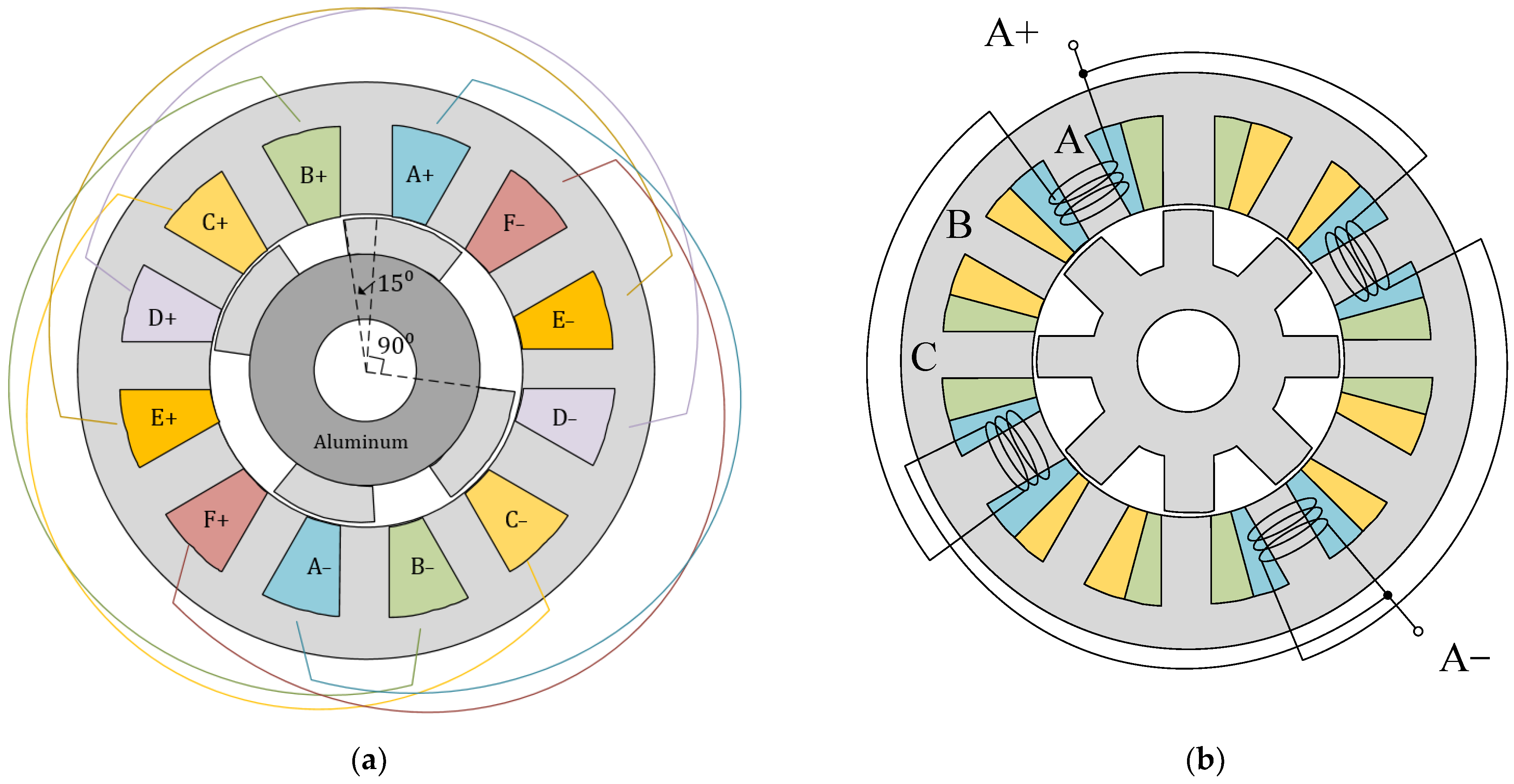
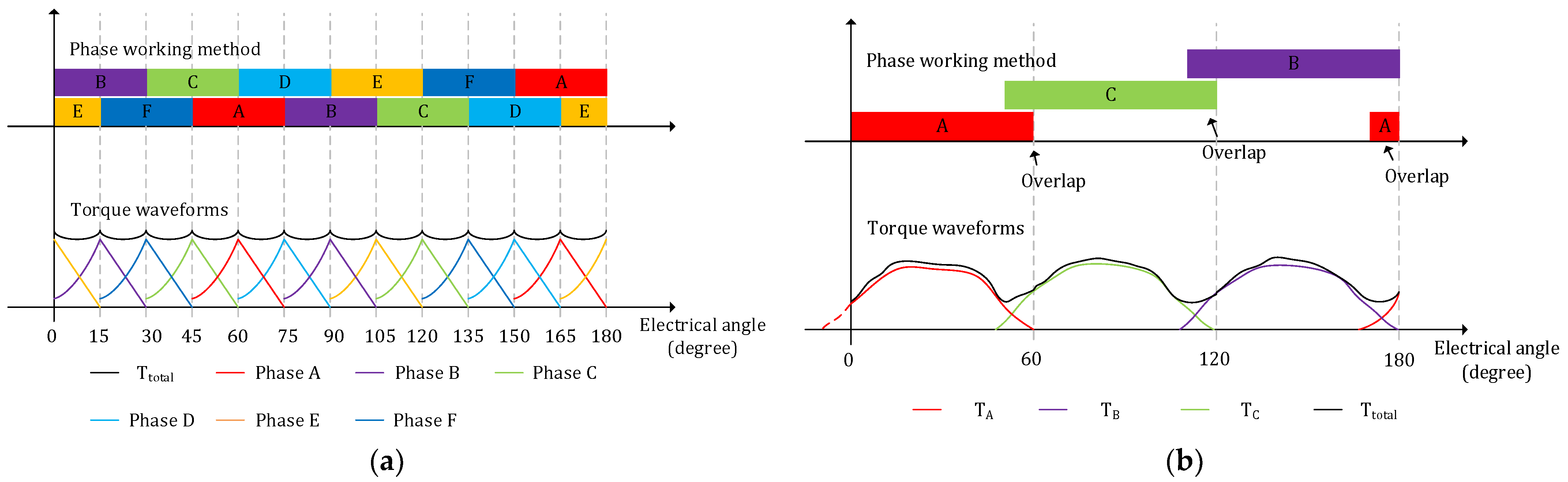
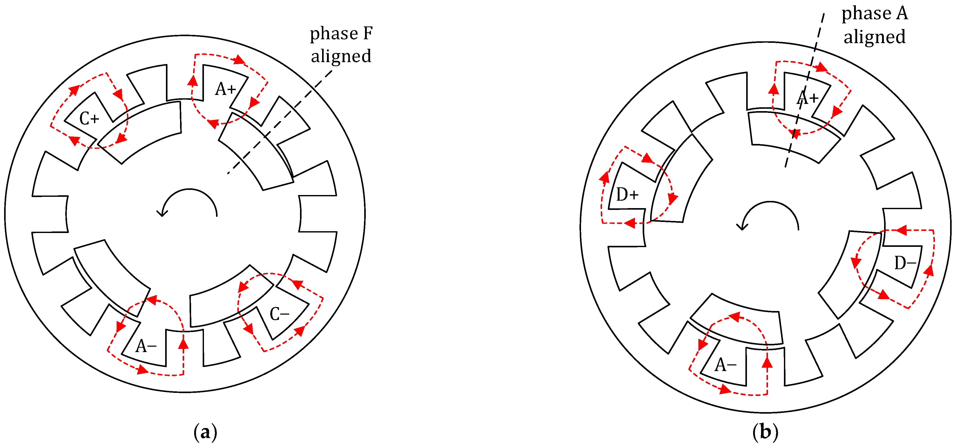
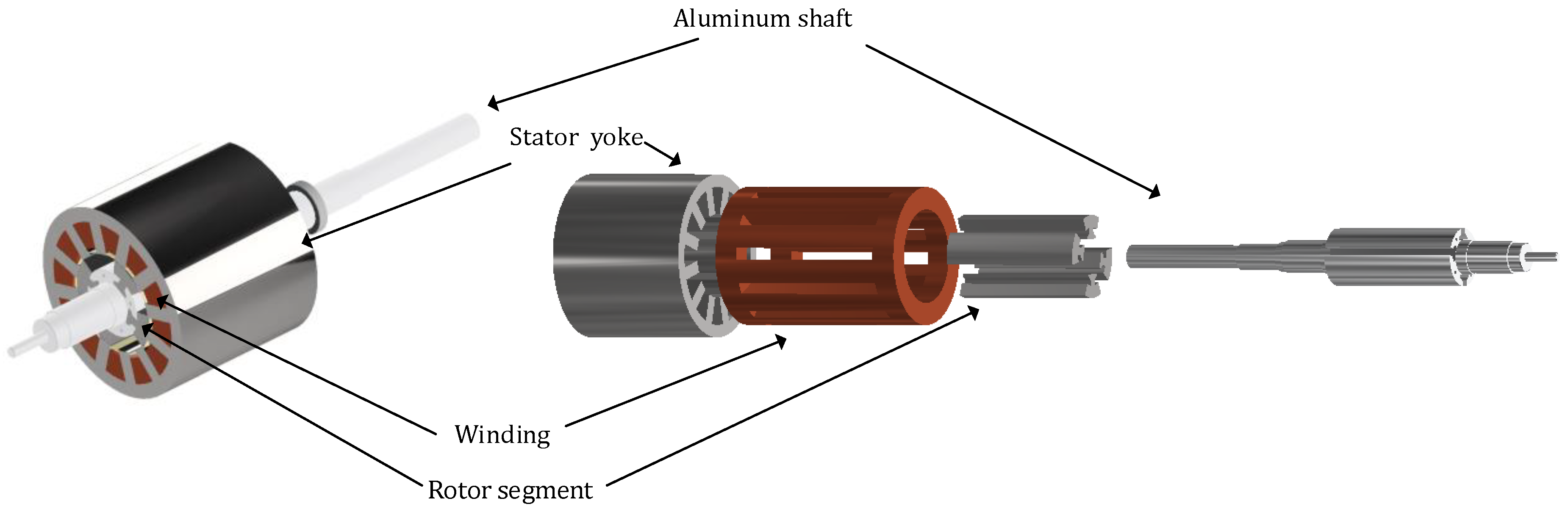
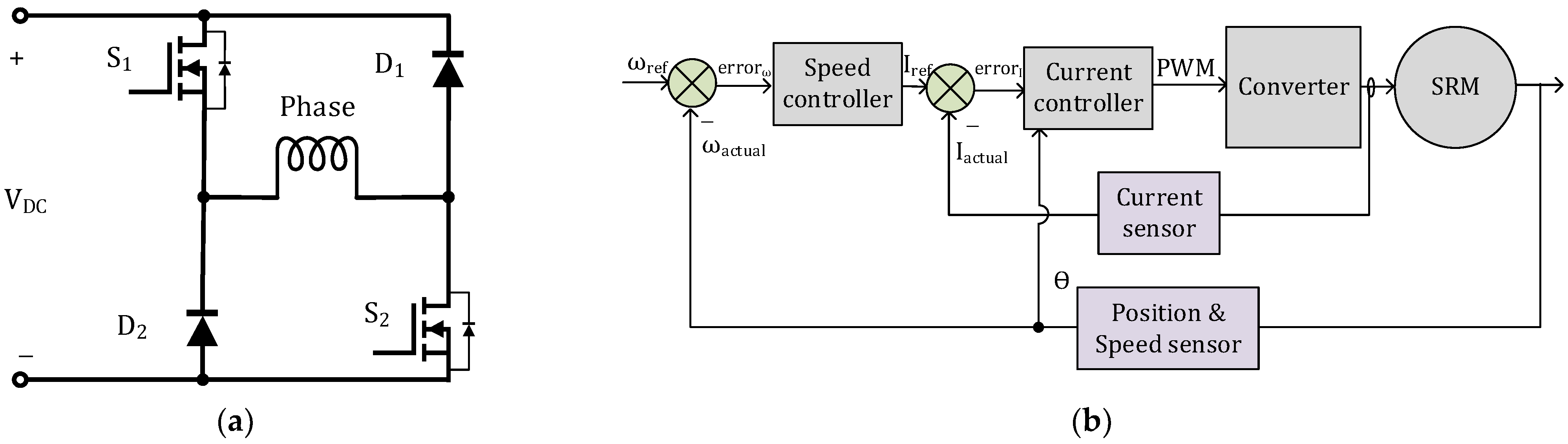
2. Structure and Operation Method of the Proposed SRM
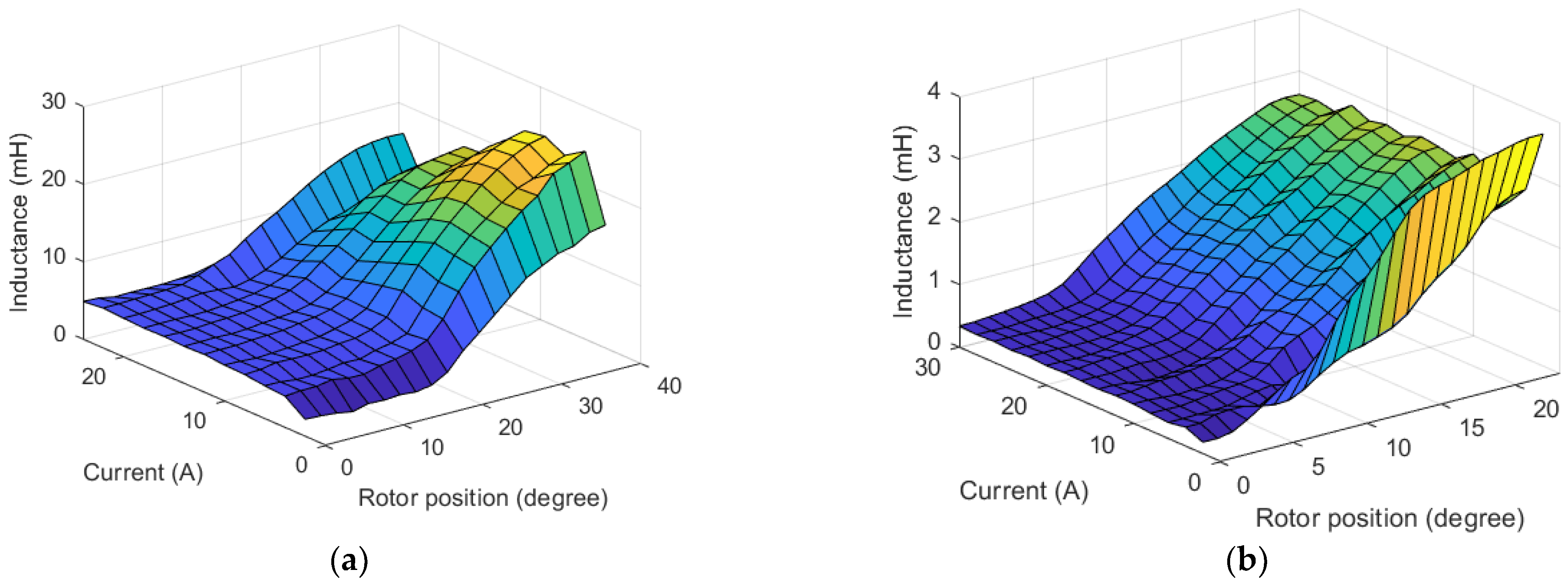
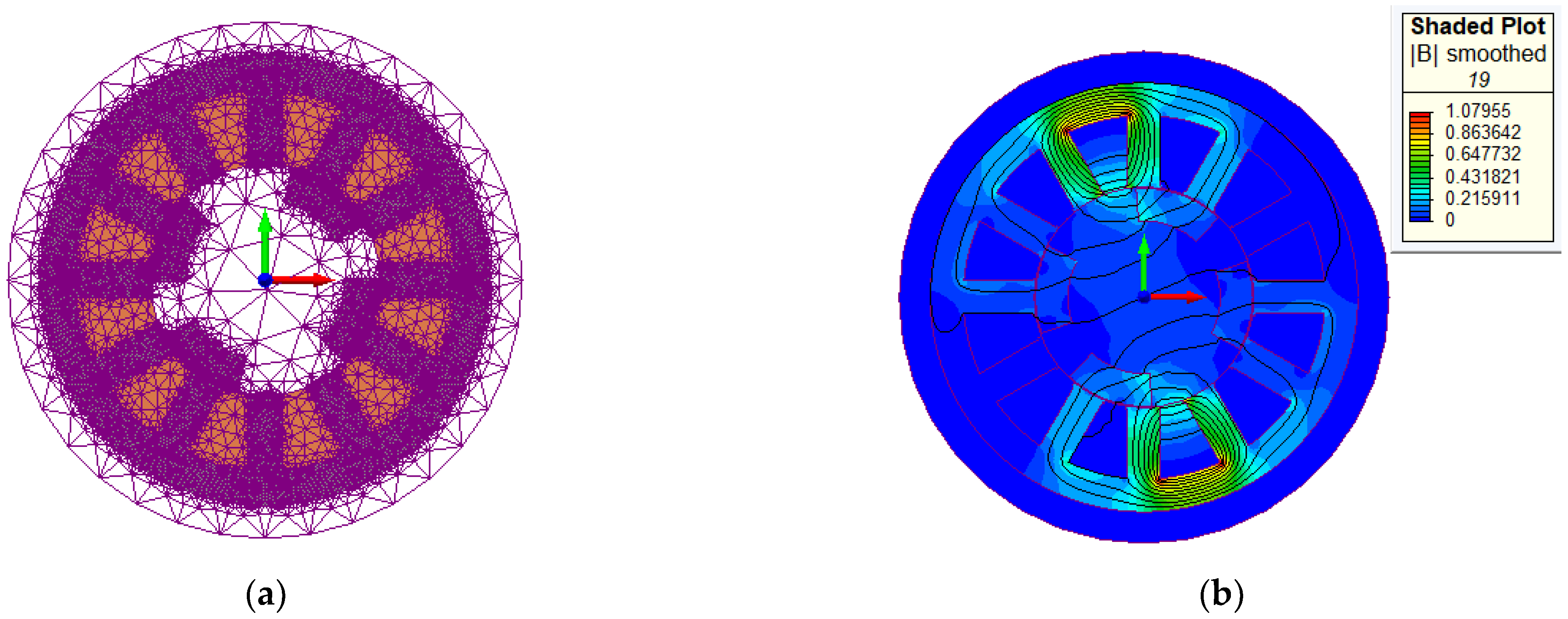
3. Electromagnetic Analysis and Optimization Method of the SRM
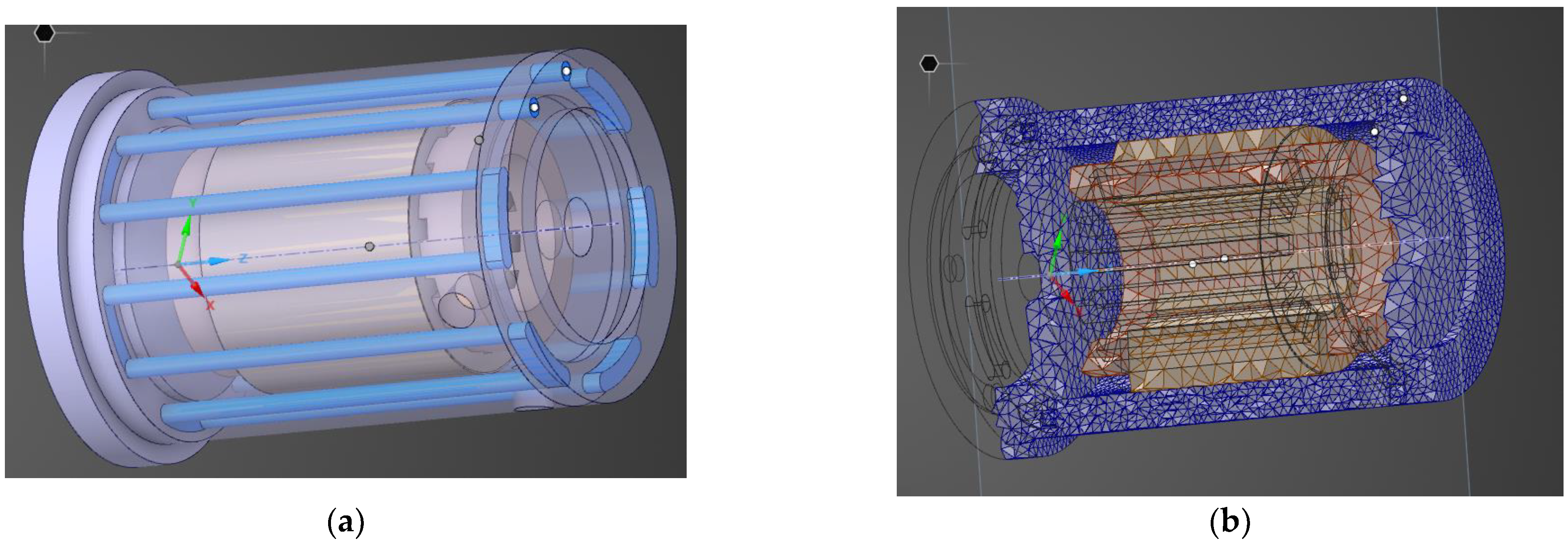
4. Cooling System Design
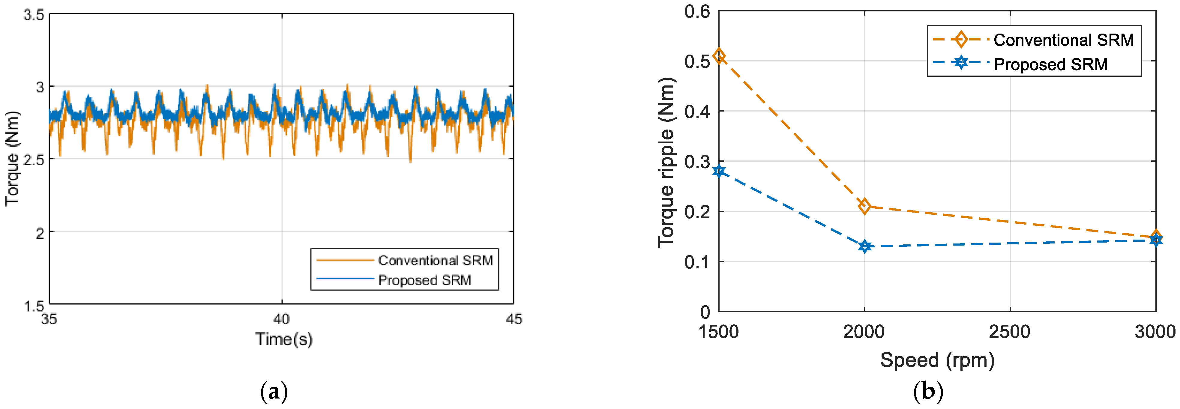
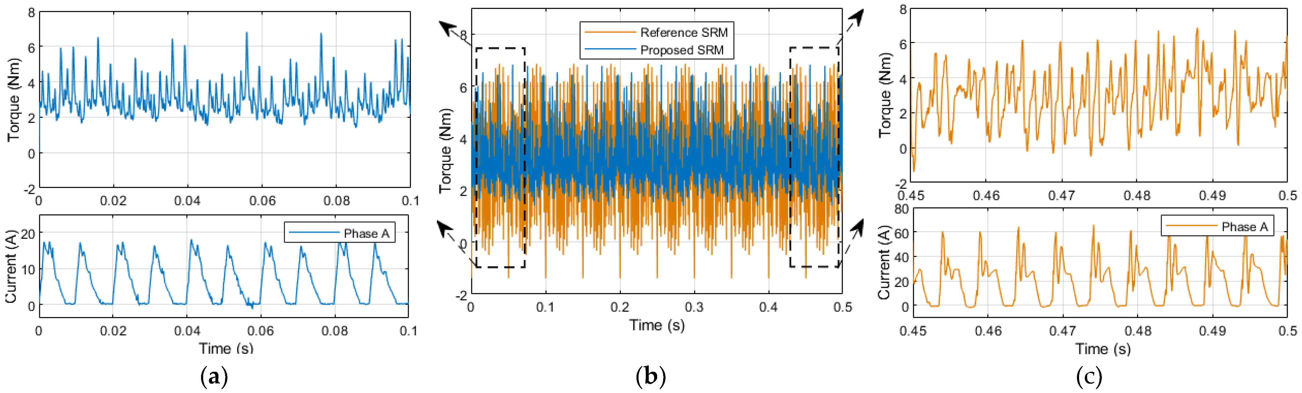
5. Simulation and Analysis
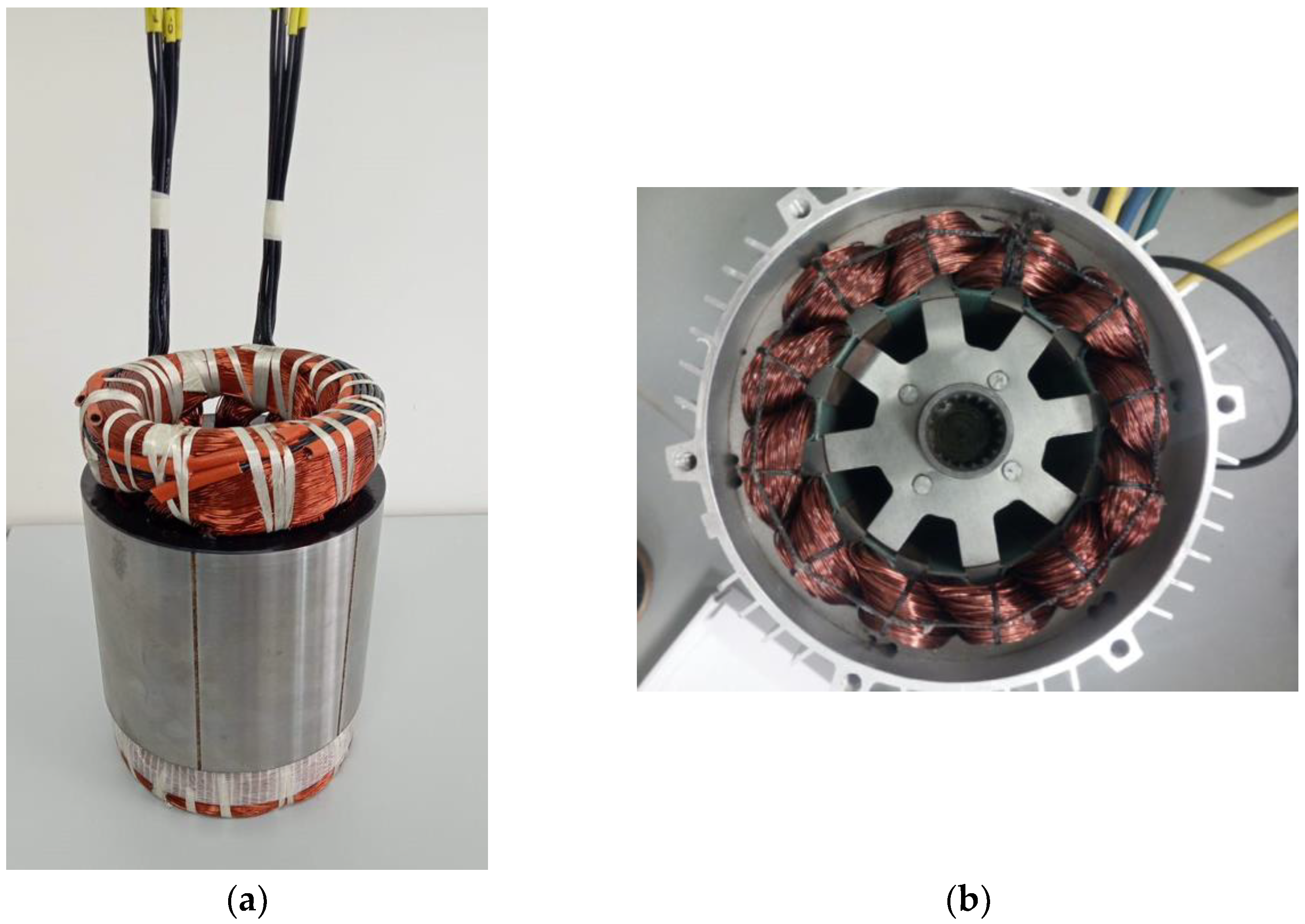
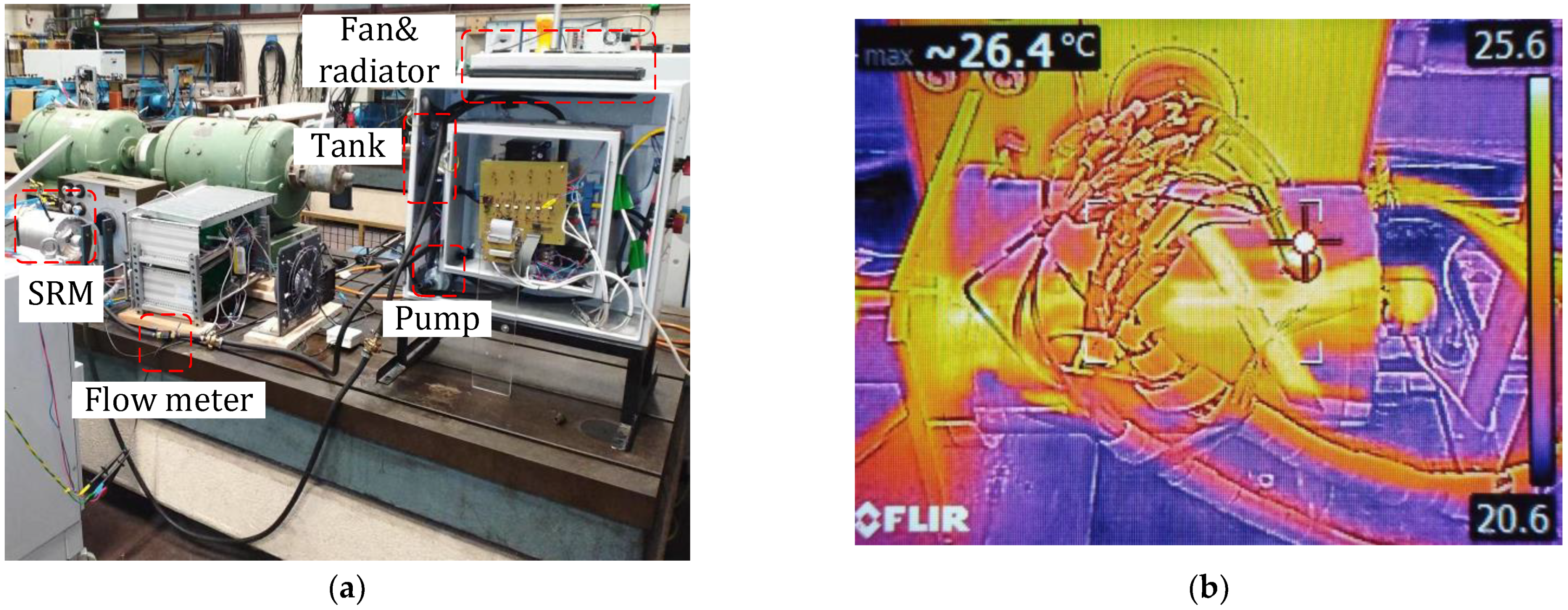
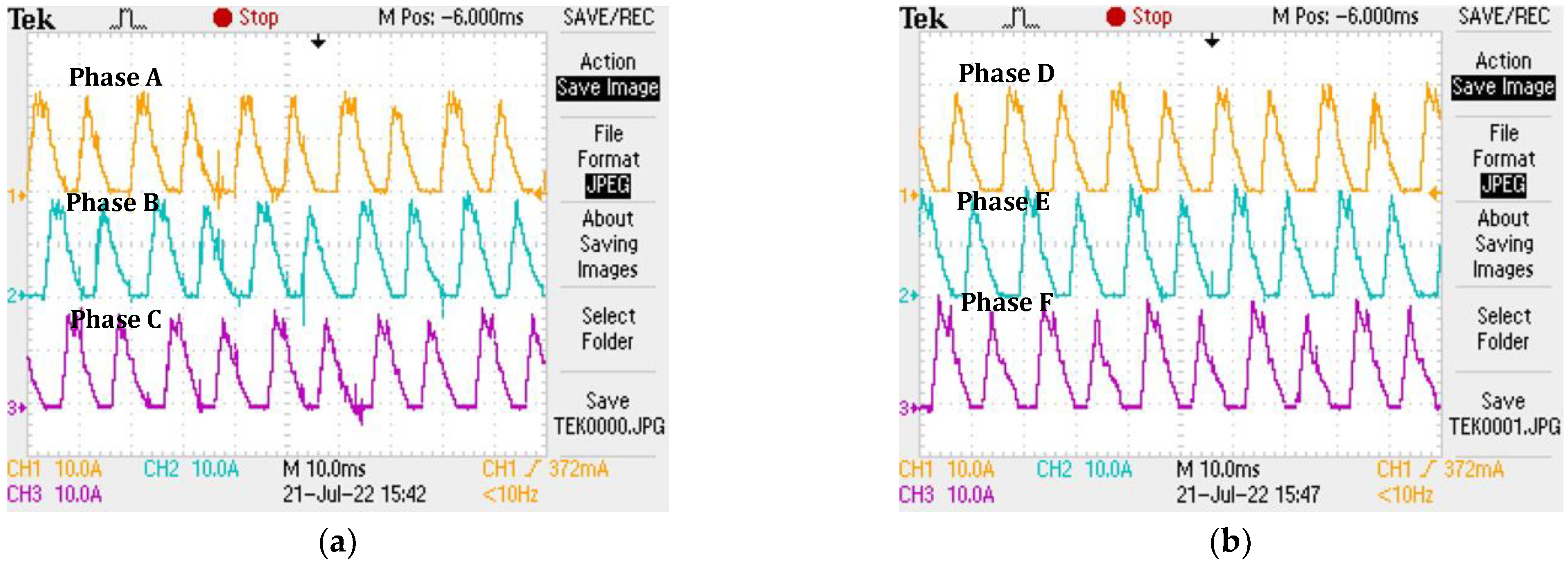
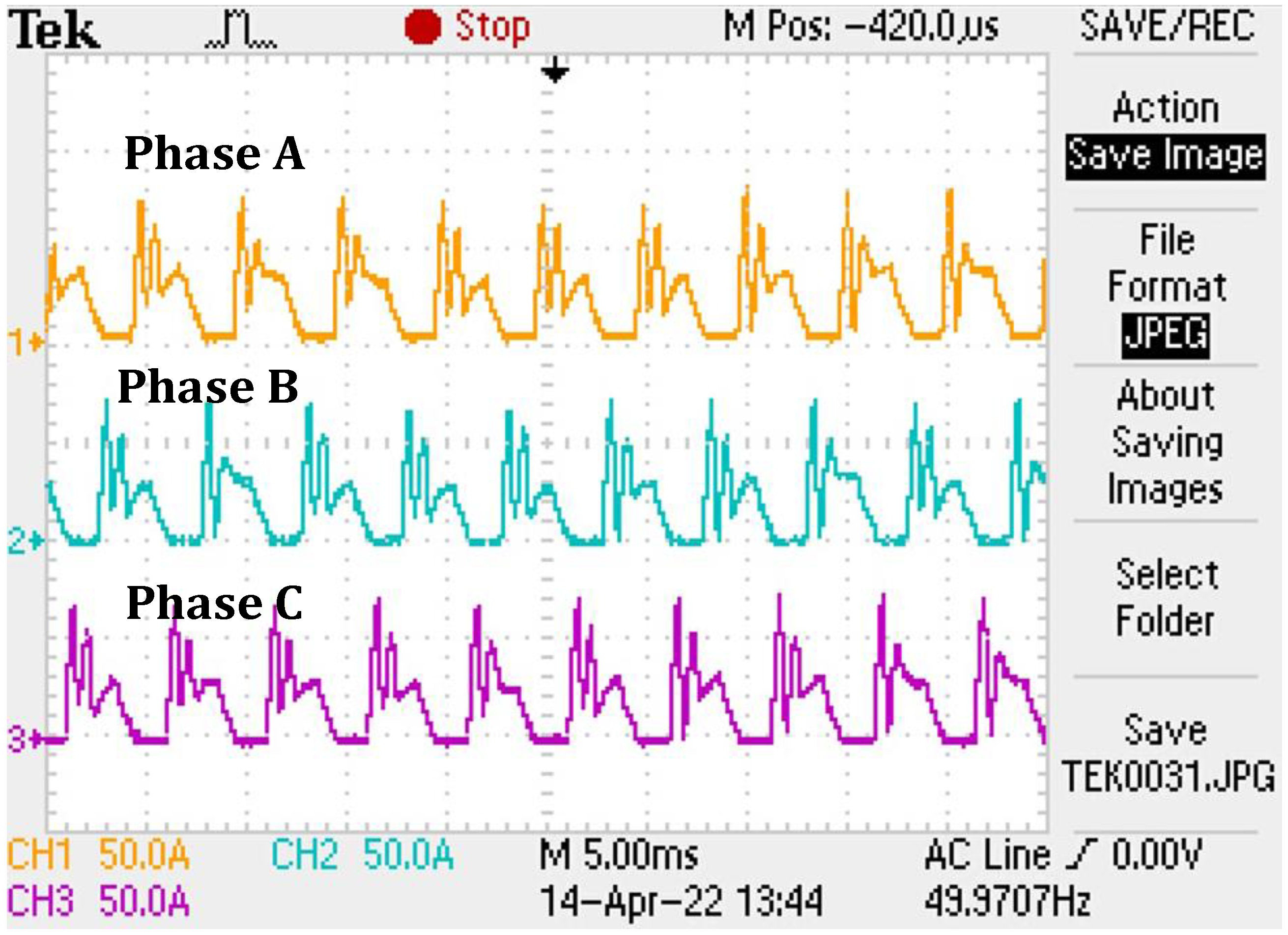
6. Prototype and Experimental Results
7. Conclusions and Future Work
Author Contributions
Funding
Institutional Review Board Statement
Informed Consent Statement
Data Availability Statement
Acknowledgments
Conflicts of Interest
References
- Kang, Z.; Hu, Y.; Sun, D. Multi-mode Drive Control System of Switched Reluctance Motor Based on a Novel N + 2 Power Converter. In Proceedings of the 2021 IEEE 4th Student Conference on Electric Machines and Systems (SCEMS), Huzhou, China, 1–3 December 2021. [Google Scholar]
- Lan, Y.; Benomar, Y.; Deepak, K.; Aksoz, A.; Baghdadi, M.E.; Bostanci, E.; Hegazy, O. Switched Reluctance Motors and Drive Systems for Electric Vehicle Powertrains: State of the Art Analysis and Future Trends. Energies 2021, 14, 2079. [Google Scholar] [CrossRef]
- Widmer, J.D.; Mecrow, B.C. Optimized Segmental Rotor Switched Reluctance Machines With a Greater Number of Rotor Segments Than Stator Slots. IEEE Trans. Ind. Appl. 2013, 49, 1491–1498. [Google Scholar] [CrossRef]
- Widmer, J.D.; Martin, R.; Mecrow, B.C. Optimisation of an 80kW Segmental Rotor Switched Reluctance Machine for automotive traction. In Proceedings of the 2013 International Electric Machines & Drives Conference, Chicago, IL, USA, 12–15 May 2013. [Google Scholar]
- Lan, Y.; Peng, W.; Aksoz, A.; Benomar, Y.; Van den Bossche, P.; El Baghdadi, M.; Hegazy, O. Design and Modelling of 12/4 Fully-Pitched Segmental Switched Reluctance Motors. In Proceedings of the 2020 Fifteenth International Conference on Ecological Vehicles and Renewable Energies (EVER), Monte-Carlo, Monaco, 10–12 September 2020. [Google Scholar]
- Siadatan, A.; Najmi, V.; Asgar, M.; Afjei, E. A new 6/4 two layers switched reluctance motor: Concept, simulation and analysis. In Proceedings of the International Aegean Conference on Electrical Machines and Power Electronics and Electromotion, Joint Conference, Istanbul, Turkey, 8–10 September 2011. [Google Scholar]
- Daldaban, F.; Ustkoyuncu, N. Multi-layer switched reluctance motor to reduce torque ripple. Energy Convers. Manag. 2008, 49, 974–979. [Google Scholar] [CrossRef]
- Afjei, E.; Torkaman, H.; Mazloomnezhad, B. A new double layer per phase configuration for switched reluctance motor. In Proceedings of the 2010 IEEE International Conference on Power and Energy, Kuala Lumpur, Malaysia, 29 November–1 December 2010. [Google Scholar]
- Siadatan, A.; Najmi, V.; Afjei, E. A novel 4/4 Multilayer Switched Reluctance Motor with 4 magnetically independent layers. In Proceedings of the International Aegean Conference on Electrical Machines and Power Electronics and Electromotion, Joint Conference, Istanbul, Turkey, 8–10 September 2011. [Google Scholar]
- Vahedi, P.; Ganji, B.; Afjei, E. Multi-layer switched reluctance motors: Performance prediction and torque ripple reduction. Int. Trans. Electr. Energy Syst. 2020, 30, e12215. [Google Scholar] [CrossRef]
- Higuchi, T.; Ueda, T.; Abe, T. Torque ripple reduction control of a novel segment type SRM with 2-steps slide rotor. In Proceedings of the The 2010 International Power Electronics Conference—ECCE ASIA, Sapporo, Japan, 21–24 June 2010. [Google Scholar]
- Khor, M.T.; Sotudeh, R. A 3-phase 12/10 asymmetrical switched reluctance motor. In Proceedings of the 2005 European Conference on Power Electronics and Applications, Dresden, Germany, 11–14 September 2005. [Google Scholar]
- Bogusz, P.; Korkosz, M.; Proko, J. Performance analysis of Switched Reluctance Motor with asymmetric stator. In Proceedings of the 2011 IEEE International Symposium on Industrial Electronics, Gdansk, Poland, 27–30 June 2011. [Google Scholar]
- Bogusz, P.; Korkosz, M.; Powrózek, A.; Prokop, J. A two-phase switched reluctance motor with asymmetrical rotor for a high-speed drive. In Proceedings of the 2015 International Conference on Electrical Drives and Power Electronics (EDPE), Tatranska Lomnica, Slovakia, 21–23 September 2015. [Google Scholar]
- Bogusz, P.; Korkosz, M.; Prokop, J. Control method of high-speed switched reluctance motor with an asymmetric rotor magnetic circuit. Arch. Electr. Eng. 2016, 65, 685–701. [Google Scholar] [CrossRef][Green Version]
- Torres, J.; Moreno-Torres, P.; Navarro, G.; Blanco, M.; Nájera, J.; Santos-Herran, M.; Lafoz, M. Asymmetrical Rotor Skewing Optimization in Switched Reluctance Machines Using Differential Evolutionary Algorithm. Energies 2021, 14, 3194. [Google Scholar] [CrossRef]
- Xu, Z.; Yu, Q.; Zhang, F. Design and Analysis of Asymmetric Rotor Pole Type Bearingless Switched Reluctance Motor. CES Trans. Electr. Mach. Syst. 2022, 6, 3–10. [Google Scholar] [CrossRef]
- Arbab, N.; Wang, W.; Lin, C.; Hearron, J.; Fahimi, B. Thermal Modeling and Analysis of a Double-Stator Switched Reluctance Motor. IEEE Trans. Energy Convers. 2015, 30, 1209–1217. [Google Scholar] [CrossRef]
- Fairall, E.; Rheberhegen, C.; Rowan, E.; Lo, J.; Bilgin, B.; Emadi, A. Maximizing thermal effectiveness and minimizing parasitic loss in a liquid cooled switched reluctance machine. In Proceedings of the 2016 IEEE Transportation Electrification Conference and Expo (ITEC), Dearborn, MI, USA, 27–29 June 2016. [Google Scholar]
- Márquez-Fernández, F.J.; Potgieter, J.H.J.; Fraser, A.G.; McCulloch, M.D. Experimental Validation of a Thermal Model for High-Speed Switched Reluctance Machines for Traction Applications. IEEE Trans. Ind. Appl. 2018, 54, 3235–3244. [Google Scholar] [CrossRef]
- Ru, L. Comparison of Vibration Between an Evaporative Cooling Switched Reluctance Motor and a Conventional Switched Reluctance Motor. In Proceedings of the 2018 21st International Conference on Electrical Machines and Systems (ICEMS), Jeju, Korea, 7–10 October 2018. [Google Scholar]
- Nonneman, J.; Schlimpert, S.; T’Jollyn, I.; De Paepe, M. Modelling and Validation of a Switched Reluctance Motor Stator Tooth with Direct Coil Cooling. In Proceedings of the 2020 19th IEEE Intersociety Conference on Thermal and Thermomechanical Phenomena in Electronic Systems (ITherm), Orlando, FL, USA, 21–23 July 2020. [Google Scholar]
- Schlimpert, S.; Mrak, B.; Siera, I.; Sprangers, R.; Nonneman, J.; De Paepe, M.; Vanhee, S. Experimental & Modelling Study of Advanced Direct Coil Cooling Methods in a Switched Reluctance Motor. In Proceedings of the 2020 IEEE Vehicle Power and Propulsion Conference (VPPC), Gijon, Spain, 18 November–16 December 2020. [Google Scholar]
- Lukman, G.F.; Nguyen, X.S.; Ahn, J.W. Design of a Low Torque Ripple Three-Phase SRM for Automotive Shift-by-Wire Actuator. Energies 2020, 13, 2329. [Google Scholar] [CrossRef]
- Ma, C.; Qu, L.; Tang, Z. Torque ripple reduction for mutually coupled switched reluctance motor by bipolar excitations. In Proceedings of the 2013 International Electric Machines & Drives Conference, Chicago, IL, USA, 12–15 May 2013. [Google Scholar]
- Grund, F.; Forsythe, G.E.; Malcolm, M.A.; Moler, C.B. Computer Methods for Mathematical Computations. Englewood Cliffs, New Jersey 07632. Prentice Hall, Inc., 1977. XI, 259 S. Z. Angew. Math. Und Mech. 1979, 59, 141–142. [Google Scholar] [CrossRef]
- Brent, R.P. Algorithms for Minimization without Derivatives; Prentice-Hall: Englewood Cliffs, NJ, USA, 1973. [Google Scholar]
- Zhou, Y.; Jiang, J.; Hu, P.; Yuan, Y. A Novel Dual-Channel Bearingless Switched Reluctance Motor. IEEE Access 2021, 9, 122373–122384. [Google Scholar] [CrossRef]
- Cailleux, H.; Mouchoux, J.C.; Multon, B.; Hoang, E.; Le Chenadec, J.Y. Comparison of Measurement Methods to Determine the Electromagnetic Characteristics of Switched Reluctance Motors. In Proceedings of the Electric Drive Design and Applications, Lausanne, Switzerland, 19–20 October 1994; pp. 639–644. [Google Scholar]
- Lukman, G.F.; Ahn, J.-W. Torque Ripple Reduction of Switched Reluctance Motor with Non-Uniform Air-Gap and a Rotor Hole. Machines 2021, 9, 348. [Google Scholar] [CrossRef]


| Parameter | Proposed SRM | Conventional SRM |
|---|---|---|
| Stator outer diameter (mm) | 139.6 | 139.6 |
| Lamination thickness (mm) | 0.35 | 0.35 |
| Stator pole height (mm) | 23.27 | 19.3 |
| Stator inner diameter (mm) | 71.62 | 84 |
| Rotor outer diameter (mm) | 71.12 | 83.5 |
| Rotor pole height (mm) | 10.72 | 14.75 |
| Air-gap length (mm) | 0.25 | 0.25 |
| Stack length (mm) | 120 | 120 |
| Number of phases | 6 | 3 |
| Number of phases working simultaneously | 2 | 1 |
| Copper winding length per phase (m) | 37.12 | 32 |
| Number of turns per phase | 64 | 64 |
| Number of stator poles | 12 | 12 |
| Number of rotor poles | 4 | 8 |
| Number of rotor pole pairs | 1 | 4 |
| Maximum average static torque (Nm) | 23.9 | 6.6 |
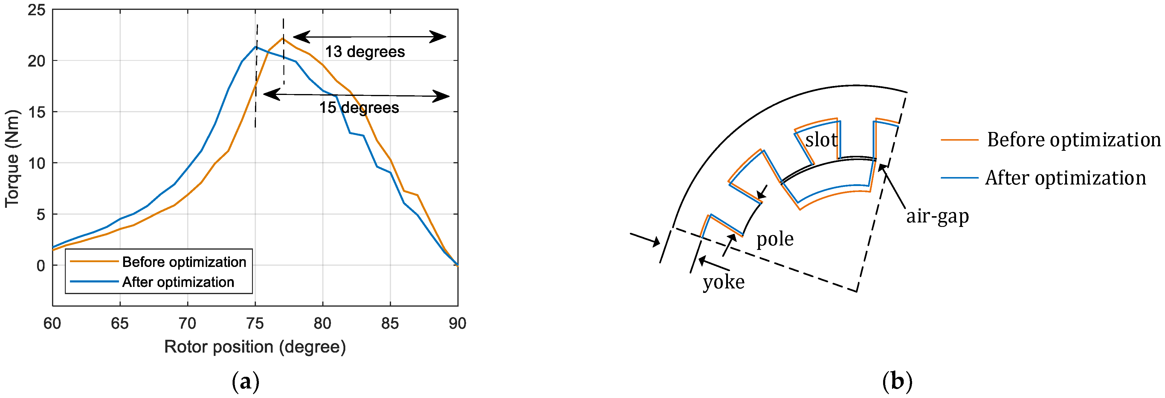
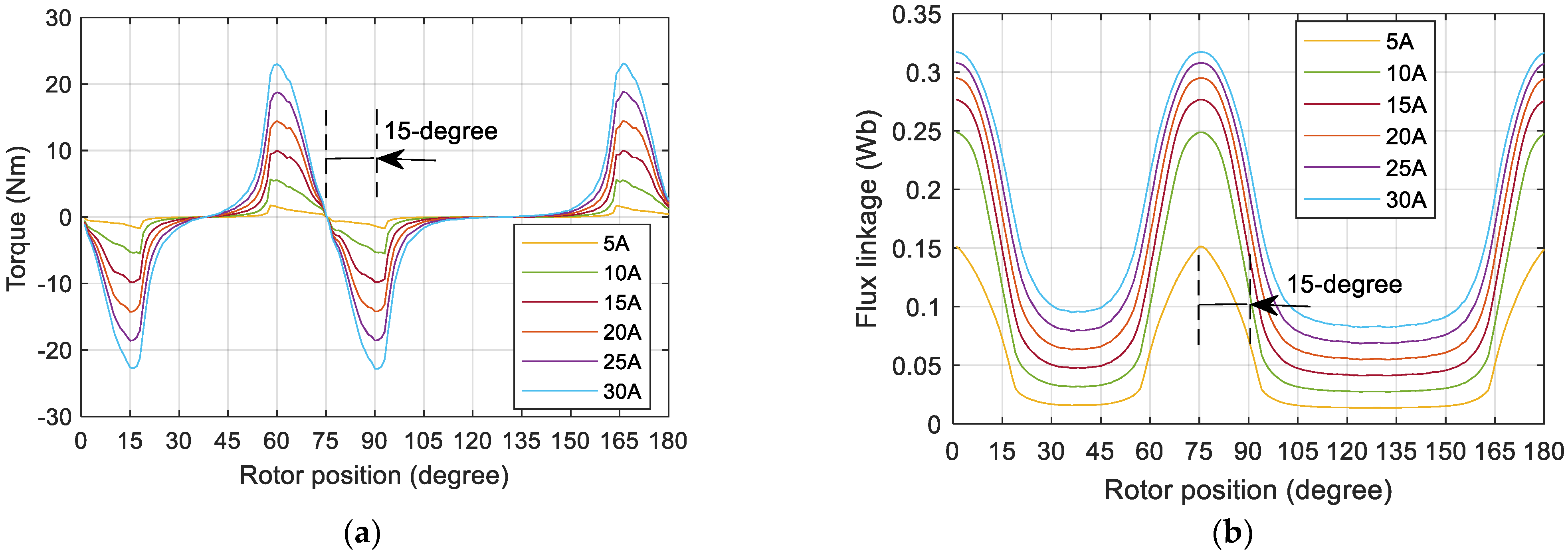
| Objective | Minimization of the distance between the maximum torque point and the 75-degree position in Figure 8a |
| Variable | Width of the pole in Figure 8b |
| Constraint | The slot area is constant in Figure 8b |
| Optimization algorithm | Golden section search and parabolic interpolation algorithms |
| Parameter | Before Optimization | After Optimization |
|---|---|---|
| Stator pole width (mm) | 5 | 5.7 |
| Rotor pole arc (degree) | 21.9 | 22.9 |
| Rotor inner diameter (mm) | 63.5 | 60.7 |
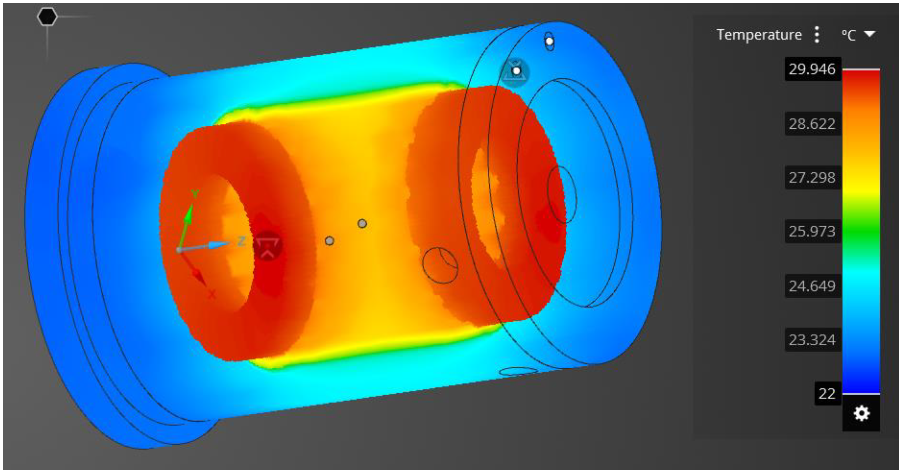
| Phase Current (A) | Copper Losses (W) | Maximum Temperature (°C) |
|---|---|---|
| 20 | 528 | 29.946 |
Publisher’s Note: MDPI stays neutral with regard to jurisdictional claims in published maps and institutional affiliations. |
© 2022 by the authors. Licensee MDPI, Basel, Switzerland. This article is an open access article distributed under the terms and conditions of the Creative Commons Attribution (CC BY) license (https://creativecommons.org/licenses/by/4.0/).
Share and Cite
Lan, Y.; Frikha, M.A.; Croonen, J.; Benômar, Y.; El Baghdadi, M.; Hegazy, O. Design Optimization of a Switched Reluctance Machine with an Improved Segmental Rotor for Electric Vehicle Applications. Energies 2022, 15, 5772. https://doi.org/10.3390/en15165772
Lan Y, Frikha MA, Croonen J, Benômar Y, El Baghdadi M, Hegazy O. Design Optimization of a Switched Reluctance Machine with an Improved Segmental Rotor for Electric Vehicle Applications. Energies. 2022; 15(16):5772. https://doi.org/10.3390/en15165772
Chicago/Turabian StyleLan, Yuanfeng, Mohamed Amine Frikha, Julien Croonen, Yassine Benômar, Mohamed El Baghdadi, and Omar Hegazy. 2022. "Design Optimization of a Switched Reluctance Machine with an Improved Segmental Rotor for Electric Vehicle Applications" Energies 15, no. 16: 5772. https://doi.org/10.3390/en15165772
APA StyleLan, Y., Frikha, M. A., Croonen, J., Benômar, Y., El Baghdadi, M., & Hegazy, O. (2022). Design Optimization of a Switched Reluctance Machine with an Improved Segmental Rotor for Electric Vehicle Applications. Energies, 15(16), 5772. https://doi.org/10.3390/en15165772