Article

Speed Control of Switched Reluctance Motor Based on Regulation Region of Switching Angle

School of Rail Transportation, Shandong Jiaotong University, Jinan 250357, China
*
Author to whom correspondence should be addressed.
Energies 2022, 15(16), 5782; https://doi.org/10.3390/en15165782
Submission received: 11 July 2022 / Revised: 2 August 2022 / Accepted: 8 August 2022 / Published: 9 August 2022
(This article belongs to the Special Issue Design and Control of Electrical Motor Drives II)

Abstract

:
This paper studies the speed control strategy of a switched reluctance motor based on angle-position control (APC). The switched reluctance motor has three control parameters: turn-on angle, turn-off angle and voltage PWM duty cycle. This paper studies the function of the three parameters and designs the control algorithms of the parameters, respectively, which can reduce the coupling degree, simplify the control process, and realize the optimal control of the switched reluctance motor. By studying the nonlinear characteristics of the switched reluctance motor, the optimal current waveform in the effective working range of the inductor is obtained, and then a control strategy of the turn-on angle is designed to realize the ideal winding current waveform. According to the torque characteristics of the motor, taking the coincidence of the freewheeling zero point and the position angle at the end of the maximum inductance interval as the control target, a control strategy for the turn-off angle that makes full use of the effective inductance working interval is proposed, which improves the efficiency of the system. For the nonlinear and time-variant switched reluctance motor running process, a data-driven model-free adaptive control algorithm is introduced, and a switched reluctance motor speed control algorithm based on voltage PWM duty cycle is designed. The main contribution of this paper is to propose a control strategy that is generally applicable to switched reluctance motors, which does not depend on the precise mathematical model of the motor. The control algorithms are designed separately for the three control parameters according to the characteristics of the motor, which reduces the degree of coupling among them. A switched reluctance motor drive system based on angle-position control is designed. This strategy is especially suitable for driving the load with sudden large torque pulsation.

1. Introduction

The switched reluctance motor has a simple strong structure and low cost and has been widely used in recent years with the development of power electronics technology [1]. The switched reluctance motor has the characteristics of saturation, nonlinearity, time-varying, etc. It is difficult to obtain an accurate mathematical model [2], and the control effect of the model-based control theory is not ideal [3]. Many scholars have devoted themselves to research on the control strategy of switched reluctance motor [4,5], in order to obtain the ideal control effect. In practical applications, the switched reluctance motor usually works in the speed regulation mode, so it is necessary to design an appropriate control strategy to track the target speed.
At present, the speed control methods of switched reluctance motors generally include direct torque control and indirect control. The direct torque control method generally fixes the turn-on angle and the turn-off angle is unchanged. According to the difference between the actual speed and the target speed, the reference torque is generated, and the actual torque is estimated according to the rotor position and the feedback current value, and then controls the switch of the power device according to the comparison value of the reference torque and the estimated torque [6]. The more commonly used torque estimation methods include look-up table method [7], support vector machine [8], neural network [9] and so on. The accuracy of the torque estimation model has a great influence on the effect of direct torque control [10]. The switched reluctance motor has nonlinear and time-varying characteristics, and its torque model changes with the speed and motor current [11]; it is not easy to achieve accurate modeling, so the effect of direct torque control is not good. Indirect control is generally a double closed-loop control method, including an inner loop and an outer loop; the outer loop is a speed loop, and the inner loop is a current loop. The speed loop generates a given signal of the current loop according to the error signal of the rotational speed, and the current loop realizes the closed-loop tracking control of the current according to the error between the given current signal and the feedback current signal. The function of the speed loop is to generate a reference current according to the difference between the actual speed and the target speed. The commonly used speed loop control algorithms include fuzzy control [12], PID control, iterative learning control [13], and synovial film control [14]. The current loop controls the switch of the power device to make the actual current value close to the reference current value [15]. Current loop includes current waveform control mode and switching angle control mode. The current waveform control method controls the current of the motor to track the reference current at any time in the entire commutation cycle [16], which is suitable for the method of changing the reference current. However, for different speeds, different loads and different motors, the reference current is different, and the torque–current modeling is difficult, so it is difficult to design a control algorithm with universal applicability. The current loop of the switching angle control method only controls the current between the opening angle and the closing angle [17], and the difficulty is still the construction of a current–torque model that conforms to the nonlinear characteristics of the motor. In fact, due to the saturation, nonlinearity, and time-varying characteristics of switched reluctance motor, it is difficult to establish an accurate current torque model in the full speed range and power range, so the control strategy of switched reluctance motor based on torque and current have certain limitations.
The switched reluctance motor has a doubly salient structure, and the torque ripple and noise are larger, especially at low speed. A large part of the above-mentioned current or torque-based speed regulation is to overcome its torque ripple and noise [18]. In fact, many applications require the motor to operate at medium or high speed, and the noise and vibration requirements of the motor are not high, such as textile, petroleum, mining machinery, etc. On the other hand, multi-pole motor structure or reducer can be used to reduce the impact of torque ripple, and a relatively simple angle-position control (APC) mode can be adopted to realize the speed regulation control of switched reluctance motor through the voltage PWM duty cycle [19]. The switch reluctance motor speed control strategy based on the angle-position method has three parameters: turn-on angle, turn-off angle, and voltage PWM duty cycle. Studies have shown that the turn-on and turn-off angles have a great influence on the efficiency and torque of the motor [20,21], and the voltage PWM duty cycle is the main parameter for speed control. Therefore, it is necessary to optimize the control strategy of the three parameters to achieve the goal of speed tracking from the perspective of improving efficiency [22]. However, there is a coupling relationship among the three parameters of turn-on angle, turn-off angle, and voltage PWM duty cycle, which greatly increases the difficulty of speed control optimization. At present, in many studies on the optimal control of a switched reluctance motor, the coupling problem of control parameters has not been well solved. Therefore, starting from the main control functions of the three parameters, this paper designs the corresponding control strategies, respectively, which greatly reduces the coupling degree among them, and realizes the speed tracking control by using the model free adaptive control algorithm.
According to the linear inductance model of the switched reluctance motor, the phase winding current outputs the driving torque in the inductance rising interval [23], and outputs the negative torque in the inductance falling interval [24]. The winding current starts to decrease gradually after the turn-off angle, when the current decreases to 0, the corresponding rotor position angle is called the freewheeling zero point. If the freewheeling zero point continues to the inductance drop range, the current will generate negative torque and reduce the system efficiency. On the contrary, when the freewheeling current drops to 0 prematurely, the inductance rise interval is not fully utilized, which will also reduce the efficiency of the motor. A reasonable turn-off angle control strategy must be designed, so that the freewheeling zero point is located near the end of the maximum inductance, so as to maximize the performance of the motor and improve the efficiency of the motor.
The nonlinear inductance model of the switched reluctance motor [7] shows that in the rising range of inductance, the saturation degree of the magnetic field increases with the increase in the inductance, resulting in a decrease in the slope of the inductance curve; even if the winding current is increased, the output torque of the motor increase is not big. The ideal current waveform is that the current is larger at the beginning of the inductance rising interval, which can generate larger torque; after that, as the inductance increases, the current gradually decreases, and the saturation of the magnetic field will decrease accordingly, which will increase the torque output capability per unit current. The voltage equation of the linear inductance model of the switched reluctance motor shows that in order to make the winding current drop in the inductance rising interval, the moving potential must be made larger than the external voltage [25], that is, a lower voltage PWM duty cycle is used. Since the duty ratio of the voltage PWM is relatively small, the turn-on angle must be reduced so that the winding current has sufficient rise time before entering the inductance rising interval, so as to ensure that it has a large enough current to generate a large torque when it enters the inductance rising interval. For a fixed external voltage, when the turn-on angle is less than a certain value θK, the current can meet the requirements of the ideal waveform. Therefore, adjusting the turn-on angle within a feasible turn-on angle range [θ1, θK] can realize the current slope in the effective range of the inductor is negative optimal current waveform.
Three parameters—the turn-on angle, turn-off angle, and voltage PWM duty cycle—have a coupling relationship in the process of speed control. According to the different control functions of the three parameters, combined with the ideal current waveform, the control strategies are designed separately, which can greatly reduce the degree of coupling among them. The main function of the turn-on angle and turn-off angle is to control the current waveform of the winding to realize the optimal control of the current. The voltage PWM duty cycle can adjust the average voltage applied to the motor to achieve a wide range of speed tracking control. Since the switched reluctance motor is nonlinear and time-varying, its model changes constantly with the working conditions. It is necessary to use an algorithm with self-adaptive ability to realize the speed tracking control according to the real-time operating data of the motor. Model-free adaptive control (MFAC) theory and method is a typical data-driven control method [26]. MFAC uses a new dynamic linearization method and a concept called pseudo partial derivative (PPD) for discrete-time nonlinear systems, establishes an equivalent dynamic linearization data model at each dynamic working point of the closed-loop system, and then designs a controller based on this equivalent virtual data model and carries out the theoretical analysis of the control system, so as to realize the adaptive control of the nonlinear system. At present, the MFAC method has been applied in driverless [27], unmanned surface vehicles [28], urban transportation network [29], power system damping control [30], motor drive control [31,32], and other fields. Both theoretical analysis and practical application show that MFAC has simple calculation and strong robustness. The most important thing is that it does not need any system model information and only needs the input and output data of the system to control, which has strong applicability. In this paper, the control algorithm is designed for the three parameters, respectively, to reduce the coupling among them, and then the data-driven model free adaptive control algorithm is introduced into the speed control of a switched reluctance motor to achieve a good speed control effect.
In the speed control method based on current chopping, the control period of the current loop is much smaller than that of the speed loop. In some sudden large torque pulsation conditions, the torque generated by the motor current is much smaller than the load torque, and the motor speed drops rapidly. For the APC speed control method based on the voltage PWM duty cycle, the output of the speed loop is the voltage PWM duty cycle, which is unchanged in a commutation period. When a sudden large torque pulsation occurs, the speed of the motor decreases rapidly, and the rotating electromotive force also decreases, so the average voltage is greater than the rotating electromotive force, the winding current of the motor increases rapidly, and the output torque also increases rapidly, that is, the output current increases following the sudden increase in the load, which can suppress the torque ripple. Therefore, the algorithm proposed in this paper has obvious advantages in controlling sudden large torque loads.
In summary, the main contributions of this paper are as follows:
(1)
A control strategy that does not depend on the exact model of switched reluctance motor is designed, which provides a feasible algorithm for switched reluctance motor control.
(2)
According to the characteristics of the switched reluctance motor, the turn-off angle control algorithm based on the optimal freewheeling zero point, the turn-on angle control algorithm based on the optimized current waveform, and the voltage PWM speed regulation control algorithm based on the model-free adaptive control are designed. The control strategies of three key parameters are designed, respectively, which greatly reduces the degree of coupling among them and simplifies the control algorithm.
(3)
The control strategy proposed in this paper can realize the speed tracking control of switched reluctance motor, especially suitable for driving loads with sudden large torque ripple.

2. Linear Model Analysis of Switched Reluctance Motor

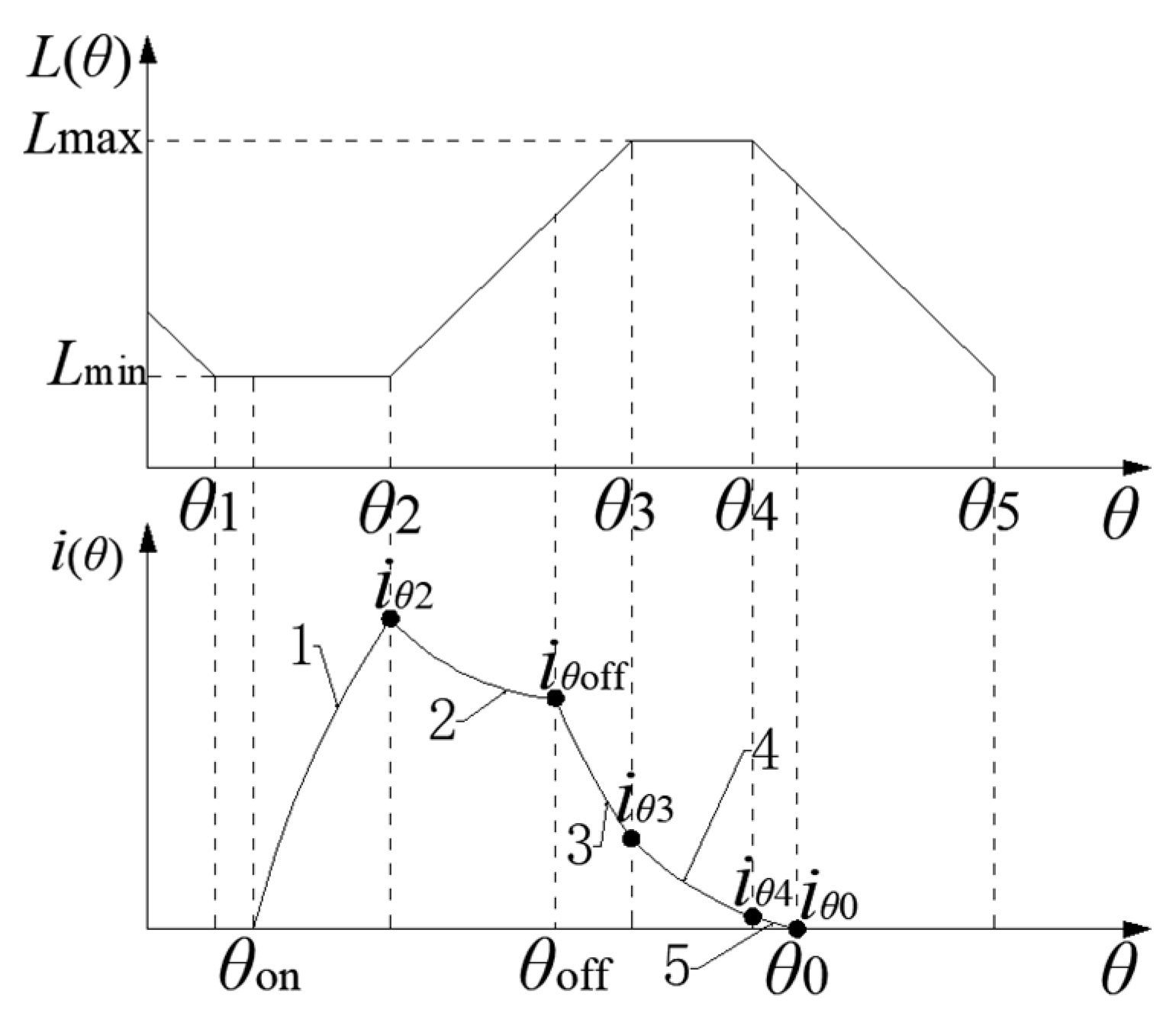
2.1. Linear Inductance Model of One Phase Winding

As shown in Figure 1, the upper part is the linear inductance curve of one-phase winding of stator, the lower part is the current curve of one-phase winding under APC control mode, the horizontal axis is the position angle of rotor θ, and the longitudinal axis is inductance L(θ) and current i(θ). Lmax is the maximum inductance value of one-phase winding, Lmin is the minimum inductance value of one-phase winding, θon is the turn-on angle, θoff is the turn-off angle, iθ2, iθoff, iθ3, iθ4 and iθ0 at the round black spot, respectively, represent the current when the rotor position angle θ is θ2, θoff, θ3, θ4 and θ0. According to the shape of the linear inductance curve, the rotor position is divided into different working sections: the minimum inductance section [θ1, θ2], inductance rising range [θ2, θ3], maximum inductance section [θ3, θ4], inductance drop range [θ4, θ5]. Curve 1 in the current curve is the current in section [θon, θ2] after the turn-on angle, curve 2 is the current when the rotor position angle θ is in the [θ2, θoff] range, curve 3 is the current when rotor position angle θ is in section [θoff, θ3], curve 4 is the current when the rotor position angle θ is in section [θ3, θ4], curve 5 is the current when rotor position angle θ is in section [θ4, θ0], and θ0 is the rotor position angle when the current drops to zero.
The linear inductance equation of the stator phase winding of switched reluctance motor is:
L ( θ ) = { L min K ( θ θ 2 ) + L min L max L max K ( θ θ 4 ) θ 1 θ < θ 2 θ 2 θ < θ 3 θ 3 θ < θ 4 θ 4 θ < θ 5
where K = (LmaxLmin)/(θ3  θ2), indicating the slope of inductance change.
The torque equation of switched reluctance motor based on linear inductance model is:
T = { 0 K i 2 ( θ ) / 2 0 K i 2 ( θ ) / 2 θ 1 θ < θ 2 θ 2 θ < θ 3 θ 3 θ < θ 4 θ 4 θ < θ 5
Equation (2) shows that the current in the two inductance sections [θ2, θ3] and [θ4, θ5] can generate torque, the current in interval [θ2, θ3] can produce output driving torque, [θ2, θ3] is called the effective working interval. The current has no torque output in the minimum inductance section [θ1, θ2] and the maximum inductance section [θ3, θ4].
The linear inductance L(θ) of stator winding is a function of rotor position angle θ, and the voltage equation of the switched reluctance motor is:
± U s = i ( t ) · R + L ( θ ) d i ( θ ) d θ ω r + i ( θ ) d L ( θ ) d θ ω r
where Us is the power voltage and “±” is the voltage direction of the winding. Assuming that one direction at both ends of the winding is “+”, the other direction is “−”, and ωr is the rotor speed. In Equation (3), the first term on the right is the resistance voltage drop of phase winding, which is represented by ur; the second item is the back potential caused by the change in current in the winding, which is called transformer potential and is represented by Ei; and the third item is the back potential generated by the winding inductance changing with the rotor position, which is called the rotating potential, and is represented by Eω.

2.2. APC Control Analysis Based on Linear Inductance Model

2.2.1. Current Analysis of Section [θ1, θ2]

As shown in Figure 1, when the rotor position angle θ is in section [θ1, θ2], the winding inductance L(θ) is the minimum value Lmin. The switch tube of the main circuit is turned on at the position angle θon, the phase winding is powered on, and the current i(θ) is generated. The initial value is 0, ignoring the winding resistance voltage drop; the third operating potential in Equation (3) is 0; and the expression of current i(θ) is:
i ( θ ) = U S ( θ θ on ) L min ω r
The change rate of current is:
d i ( θ ) d t = U S L min = c o n s t > 0
Equations (4) and (5) shows that the current of phase winding rises rapidly in the minimum inductance range. The smaller the θon, the longer the current rise time, the greater the winding current iθ2 when the rotor reaches position θ2, and the greater the torque generated by the motor in the effective inductance range [θ2, θ3].

2.2.2. Current Analysis of Section [θ2, θoff]

[θ2, θoff] is located in the front section of section [θ2, θ3], and the winding current can generate torque in this section. Bring θ2 into Equation (4), which can obtain the initial current value i(θ2) in section [θ2, θoff], ignore the winding resistance, and use Equations (1) and (3) to obtain the function of winding current varying with θ in this rotor position range:
i ( θ ) = U S ( θ θ on ) ω r [ L min + K ( θ θ 2 ) ]
The change rate of current is:
d i ( θ ) d t = U S [ L min + K ( θ o n θ 2 ) ] [ L min + K ( θ θ 2 ) ] 2
Equation (7) shows that the turn-on angle θon determines the sign of current change rate. The winding current curves with different turn-on angles are shown in Figure 2. Curves 1, 2, and 3 represent the current changes when the turn-on angles are θon1, θon2 and θon3, respectively. The turn-off angle of the three curves is the same, and the winding currents at turn-off angle are, respectively, iθoff1, iθoff2 and iθoff3. θ01, θ02 andθ03 are the rotor position angles when the winding current drops to 0. The sign of the winding current change rate needs to be discussed in three cases.
(1)
θon < θ2Lmin/K
θon is relatively small, the current change rate is less than 0, the current gradually decreases in the rising range of inductance, and its initial value i(θ2) is relatively large. The sum of transformer potential Ei and rotating potential Er is greater than the supply voltage Us, resulting in the decrease in current i(θ), as shown in curve 1 in Figure 2.
(2)
θon = θ2Lmin/K
The current change rate is equal to 0, the current remains unchanged in the inductance rising region, and the sum of transformer potential Ei and rotating potential Er is equal to power supply voltage Us, as shown in curve 2 in Figure 2.
(3)
θon > θ2Lmin/K
The change rate of current is greater than 0, the current increases in the rising region of inductance. θon is relatively large, the initial value of current i(θ2) is relatively small, the sum of transformer potential Ei and rotating potential Er is less than power supply voltage Us, and current i(θ) rises, as shown in curve 3 in Figure 2.
To generate the same average torque, the starting current of curve 1 is large, and the turn-off angle is small. According to Equation (2), the motor will produce large torque ripple. The starting current of curve 3 is small, so the turn-off angle must be increased. Considering the saturation nonlinearity of the motor, the saturation degree of the motor increases and the efficiency decreases during the gradual increase in the current, and the freewheeling current of curve 3 is likely to continue to the area where the inductance decreases, resulting in negative torque, further reducing the efficiency of the motor. For curve 2, the winding current remains unchanged in the inductance rising range, and the motor outputs a constant torque, which is ideal.

2.2.3. Current Analysis Current Analysis of Section [θoff, θ3]

This section is at the rear of inductance rising section [θ2, θ3], the power tube of the controller is closed, and the winding current flows into the power through the freewheeling diode. In Equation (3), the symbol in front of Us is “−”, the direction of transformer potential Ei is the same as that of current, the direction of rotating potential Er is the same as that of (−Us), and the current drops rapidly, as shown in curve 3 in Figure 1. Bring θoff into Equation (7) to obtain the initial current, ignore the winding resistance voltage drop, and the analytical expression of freewheeling current i(θ) is:
i ( θ ) = U S ( 2 θ off θ on θ ) ω r [ L min + K ( θ θ 2 ) ]
It is known from Equation (2) that the freewheeling current can still generate driving torque in this section, so the turn-off angle θoff should be increased as much as possible to increase the effective driving torque.

2.2.4. Current Analysis of Section [θ3, θ4]

The inductance in this section is the maximum value Lmax, the symbol in front of Us in Equation (3) is “−”, the rotating potential Er becomes 0, the direction of transformer potential Ei is the same as the current direction, and the phase current decreases slowly. Bring θ3 to Equation (8) to obtain the initial current, ignore the winding resistance voltage drop, and the analytical expression of freewheeling current i(θ) is:
i ( θ ) = U S ( 2 θ off θ on θ ) ω r L max
The change rate of current is:
d i ( θ ) d t = U S L max = c o n s t < 0
The current in this section gradually decreases, but due to the large inductance value, the rate of current decline slows down, as shown in curve 4 in Figure 1. According to Equation (2), the freewheeling current in this stage does not output torque but feeds back to the power.

2.2.5. Efficiency Analysis of Motors in APC Mode

In the APC control mode of fixed voltage, the smaller θon is, the longer the energization time of the phase winding is, and the larger the current iθ2 in Figure 2 is. On the contrary, the larger the θon is, the shorter the energization time of the phase winding is, and the smaller the current iθ2 is.
Figure 3 shows the winding current waveform when the turn-off angle θoff is the same and the turn-on angle θon is different, in which θon1, θon2, and θon3 are three different turn-on angles, θoff is the turn-off angle, and θm is the rotor position angle where the current of curve 3 reaches Ilim, L is the inductance curve, Lmax is the maximum inductance, and Lmin is the minimum inductance. Assume that the target current of the winding at θ2 is Ilim, the curves 1 to 3 are the current waveforms of the winding in the minimum inductance interval at different turn-on angles, and the curves 4 and 5 are the current waveforms of the winding in the interval [θ2, θoff], respectively.
Assuming that the winding current needs to reach Ilim at θ2, the turn-on angle θon1 of curve 3 in Figure 3 is small, the current rises rapidly, reaches Ilim at θm(θm < θ2), and then remains at Ilim until θ2 position. According to Equation (2), the inductor current has no torque output in the interval [θon1, θ2], and the current in the interval [θm, θ2] only produces copper loss in the winding, which reduces the efficiency of the motor. The current of curve 2 in Figure 3 just reaches Ilim at θ2, there is no excess loss, and the efficiency is high. Curve 4 and curve 5 in Figure 3 are the current waveforms when the inductor enters the effective interval [θ2, θ3]. The turn-on angle θon3 of curve 1 is larger, the current rise time is shorter, and the winding current at θ2 is smaller. After entering the inductance rising interval, the current continues to rise, as shown in curve 5 in Figure 3. When entering the effective range of the inductance [θ2, θ3], the current is small and the output torque is also small. With the gradual saturation of the inductance, although the current increases, the increase in the output torque is not large, resulting in lower efficiency of the motor. The effect of curve 4 in Figure 3 is better. In the non-saturation stage of the effective range of the inductor, the current is larger and the output torque is larger. With the increase in the inductance, the current gradually decreases, which will reduce the saturation degree of the inductor and increase the torque output capacity per unit current and improve the efficiency of the motor.
To sum up, from the perspective of improving the motor efficiency, the turn-on angle θon and the voltage PWM duty cycle DPWM should be adjusted comprehensively so that the winding current just reaches the maximum value Ilim at θ2 and the current gradually decreases in the rising range of the inductance, as shown in curve 2 and curve 4 in Figure 3. This is precisely the current waveform that can be achieved with APC control.

2.2.6. Analysis of Optimal Turn-Off Angle

Under the same working conditions, the larger the phase current iθoff at the θoff position, the longer the current freewheeling time, as shown in Figure 2, iθoff1 < iθoff2 < iθoff3, and the corresponding rotor position where the freewheeling current drops to zero θ01 < θ02 < θ03. If the turn-off angle θoff is large, the freewheeling current will cross θ4 and enter interval [θ4, θ5], as shown in the freewheeling zero point θ03 shown in Figure 2. From Equation (2), the freewheeling current will generate negative torque, reducing the efficiency of the motor, and is also prone to torque ripple. On the contrary, if the turn-off angle θoff is small, the freewheeling current drops to 0 earlier than θ4, which shortens the power supply time of the power supply to the windings in the effective working range [θ2, θ3]; the freewheeling zero point θ01 is shown in Figure 2. If the same average torque is to be generated, the duty cycle of the voltage PWM must be increased to increase the winding current, which will increase the torque ripple of the motor and reduce the performance of the motor. The turn-off angle θoff2 of the current curve 2 in Figure 2 is ideal, and the position angle θ02 at which the freewheeling current drops to 0 coincides with θ4, which not only makes full use of the effective working range of the inductance that can output torque but also does not produce negative torque.

3. Switched Reluctance Motor Control Considering Nonlinearity

When a switched reluctance motor operates with load, it has strong nonlinearity and saturation. It is difficult to obtain a good control effect only by the linear inductance model. It is necessary to analyze the influence of saturation and nonlinearity on the motor model and design the corresponding control strategy.

3.1. Simulation Analysis of Nonlinear Inductance Model

Figure 4 shows the inductance curve of one-phase winding of switched reluctance motor obtained by finite-element simulation analysis. The horizontal axis is the rotor position angle and the vertical axis is the winding inductance. With the gradual increase in excitation current of phase winding, the nonlinear inductance curve has the following characteristics:
(1)
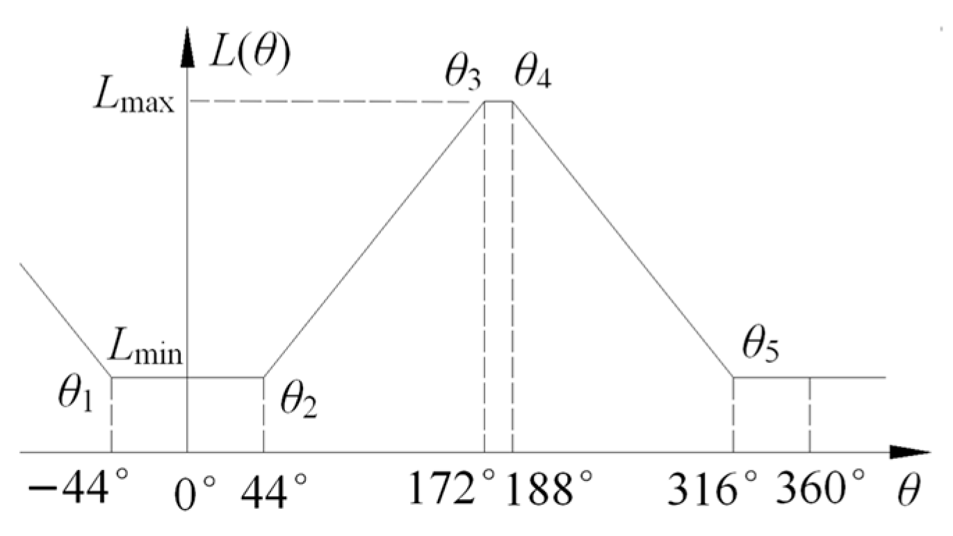
The position angle θ2, θ3, θ4, θ5 is given according to the structural dimensions of the motor, and there is no clear dividing line for the inductance curve during the actual operation of the motor.
(2)
With the increase in winding current, the rising slope of inductance in the effective working range gradually decreases. Although the winding current increases, the output torque does not increase in proportion to the square of the current.
(3)
Generally, the maximum inductance range of switched reluctance motor is designed to be small, and the inductance in this region is an approximately flat top wave when the motor is running. With the increase in rotor position angle θ, the inductance gradually increases in section [θ2, θ3], with the increase in load current, the saturation degree of the inductance becomes more and more serious, resulting in a gradual decline in the inductance, showing nonlinear characteristics. From the point of view of a switched reluctance motor design, this saturation characteristic is necessary, which is conducive to the performance of the switched reluctance motor, which determines that the switched reluctance motor has the characteristics of saturation and nonlinearity. With the increase in load current, the saturation degree of the maximum inductance section becomes more serious, and the inductance value decreases gradually, which is equivalent to increasing the width of the maximum inductance section.
(4)
After the switch tube of phase winding is turned off, the winding current gradually decreases, and the winding inductance will gradually withdraw from saturation, so the current in the inductance range [θoff, θ3] can also output large torque.

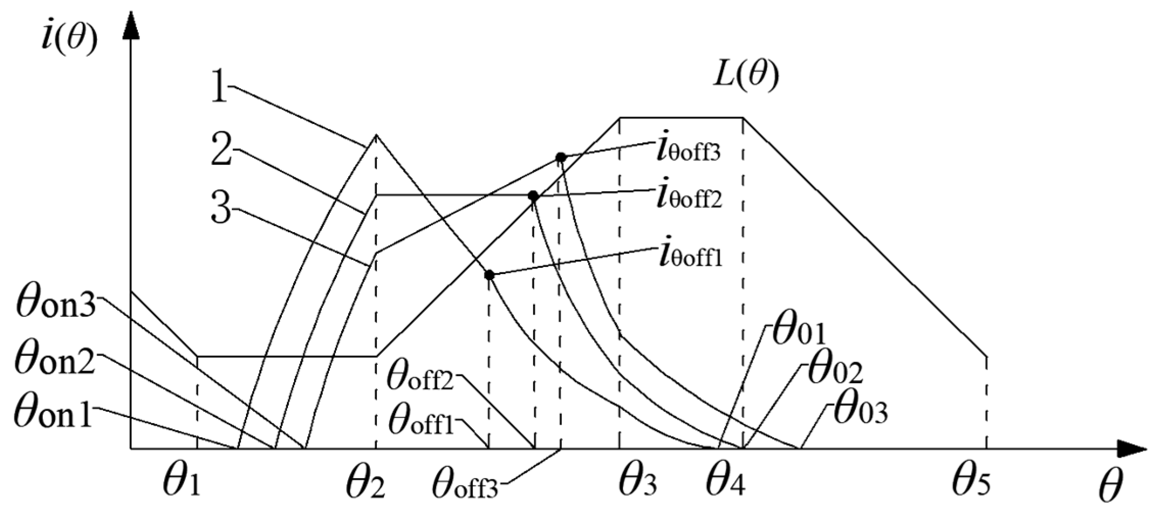
3.2. Switching Angle Control Considering Nonlinear Characteristics

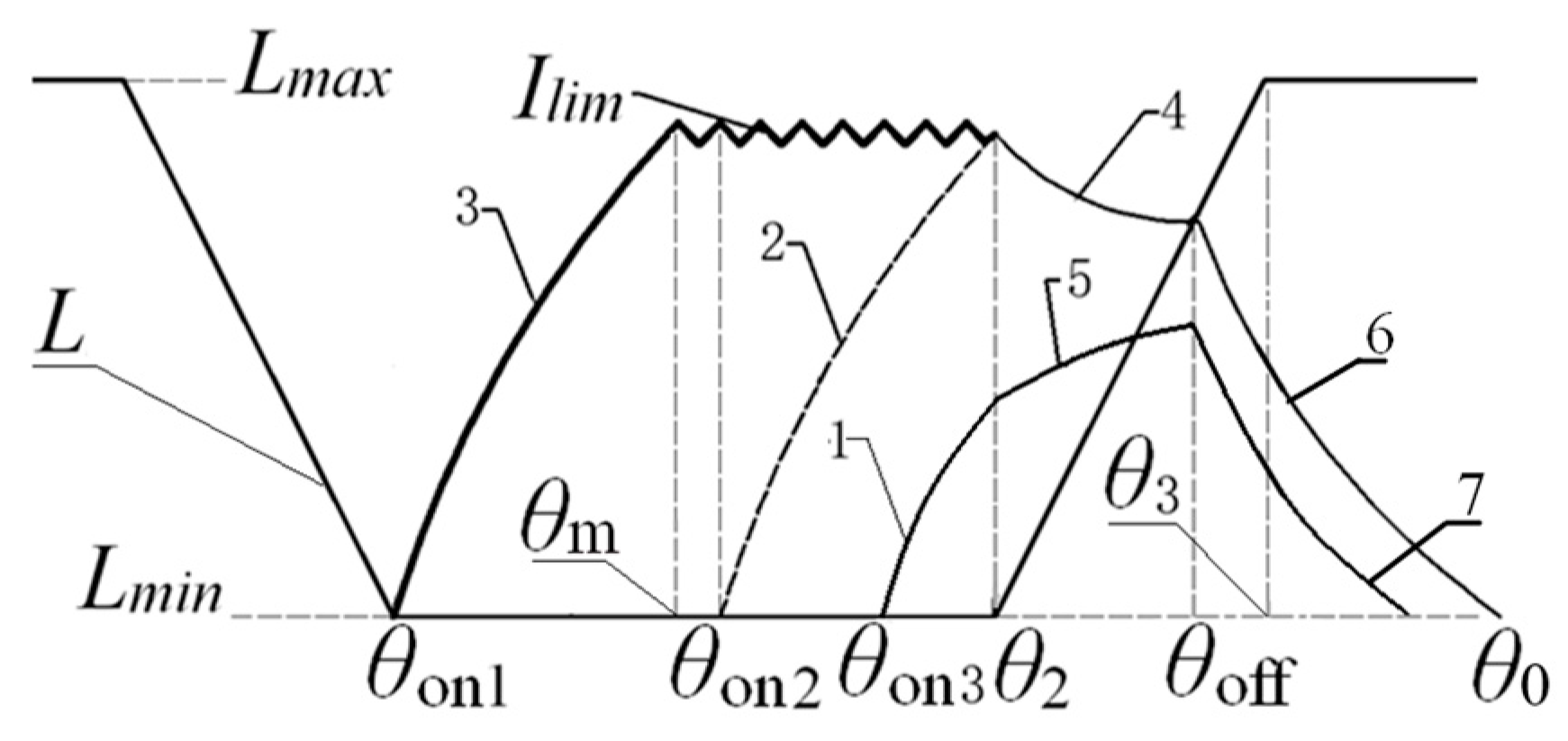
3.2.1. Optimal Winding Current Waveform

Considering the saturation of the winding inductance, the current waveform curve 1 in Figure 2 is ideal. When the rotor is at θ2, the value of the winding current iθ2 is large, and the inductance is not saturated at the initial stage of interval [θ2, θ3], so it can output a large torque. With the increase in rotor position angle θ, the inductance tends to saturation, and increasing the current is not conducive to the increase in torque. Therefore, the winding current should be appropriately reduced, which is conducive to reducing the saturation degree of inductance, reducing the iron loss of the motor and improving efficiency.
According to Equation (3), to reduce the current in the interval [θ2, θ3], it is necessary to make the motion potential Er greater than the external voltage Us. As the winding current drops, the transformer potential Ei is negative, releasing energy to maintain the winding current. From Equations (6) and (7), to obtain the current waveform of curve 1 in Figure 2 and to gradually reduce the current in the effective range [θ2, θ3] of the inductance, the opening angle must satisfy the inequality θon < θ2Lmin/K.
Therefore, to realize the current waveform shown in curve 1 in Figure 2, the duty cycle of the voltage PWM should be reduced as much as possible, and the average voltage Us of the winding should be reduced. This requires reducing the turn-on angle θon and increasing the energization time in the [θon, θ2] interval, so that the current iθ2 obtains a larger value at θ2. Since Us is small, the winding current gradually decreases in the [θ2, θoff] interval, thus obtaining an ideal current waveform.

3.2.2. Optimal Control of Turn-On Angle θon

It can be seen from the above analysis that due to the nonlinear characteristics of the switched reluctance motor, the ideal current curve of the motor is shown in curve 1 in Figure 2 during APC speed control. Set θK = (θ2Lmin/K), in the interval [θ2, θoff], the slope of the winding current should be less than zero, and the value range of the turn-on angle θon should be [θ2, θK]. For different load currents, the saturation degree of the winding inductance is different, and θK varies with the winding current.
Therefore, the optimal control strategy of the turn-on angle θon needs to determine the value of θK and the control method of θon. When the motor is running stably, if the turn-on angle θon is reduced, the charging time of the winding in the interval [θon, θ2] will become longer, the current iθ2 at θ2 position will become larger, and the motor speed will increase accordingly. In order to maintain the stable operation of the motor, it is necessary to reduce the duty cycle of the voltage PWM, that is, to reduce the voltage US in Equation (3), so that the amplitude of the rotating electromotive force Er exceeds US, and finally, the winding current in the interval [θ2, θoff] is decreased. This shows that when the turn-on angle θon is adjusted in the bounded interval [θ2, θK], the slope of the winding current in the interval [θ2, θoff] can also change monotonically in a bounded interval. Therefore, the PI adjustment algorithm with self-adaptive ability can realize the slope control of the winding current in the interval [θ2, θoff], and its stability can be guaranteed.
Suppose the current at θ2 is iθ2, the current at θoff is iθoff, and Δi is the difference between them, namely:
Δ i ( k + 1 ) = i θ 2 ( k ) i θ off ( k )
Design the PI control rule with limiting function as shown in Equation (12):
θ on ( k + 1 ) = { θ 1 K pon · [ Δ i ( k ) σ ] + j = 0 k K Ion · [ Δ i ( k ) σ ] θ K θ on ( k + 1 ) θ 1 θ 1 < θ on ( k + 1 ) < θ 2 θ on ( k + 1 ) θ 2
where θon(k + 1) is the turn-on angle, Kpon is the proportional coefficient, KIon is the integral coefficient. σ is the preset current difference. The purpose of setting σ is to ensure that iθ2 is greater than iθoff, so that the slope of the current in the [θ2, θoff] interval is negative, so the value of σ can be set to a smaller value, such as 1~2 A. Taking the slope of the winding current in the interval [θ2, θoff] to be a negative value close to 0 as the target, the maximum turn-on angle θon that makes the current slope negative can be calculated by using Equation (12), taking θon as θK, the value range [θ1, θK] of the turn-on angle can be obtained. Since the inductance of the switched reluctance motor is nonlinear, the value of θK varies, and its calculation method is shown in Equation (13). When (Δiσ) < 0, use Equation (12) to calculate θK until (Δiσ) ≥ 0, and then keep θK unchanged. Thus, the value range [θ1, θK] of the turn-on angle is determined.
θ K = { θ K θ on ( k + 1 ) Δ i ( k ) σ 0 Δ i ( k ) σ 0
When the duty cycle of the voltage PWM is kept at a certain fixed value, the turn-on angle θon can adjust the motor speed within a certain range, so a PI speed control algorithm based on the turn-on angle is designed, as shown in Equation (14).
θ on ( k + 1 ) = { θ 1 K sp · [ ω f ( k ) ω * ( k ) ] + j = 0 k K si · [ ω f ( k ) ω * ( k ) ] θ K θ on ( k + 1 ) θ 1 θ 1 < θ on ( k + 1 ) < θ K θ on ( k + 1 ) θ K
where ωf is the feedback motor speed, ω* is the set motor speed, Ksp is the proportional coefficient, and Ksi is the integral coefficient. The value of θon is limited to the interval [θ1, θK] by the clipping function. Equation (14) is a discrete PI control algorithm, and its control period is the commutation period Ts of the switched reluctance motor, which can be used as the inner loop of speed control to adjust the speed of the motor within a certain range. The speed control based on the voltage PWM duty cycle can adjust the motor speed in a wide range, which is the outer loop of the speed control, and its control period can be set to more than ten times the commutation period Ts. In the voltage PWM control period, the speed is adjusted by the turn-on angle. When the target speed increases or the load torque increases, the motor speed must be adjusted by increasing the voltage PWM duty cycle if θon decreases to θ1. On the contrary, when the target rotational speed decreases or the load torque decreases and if θon increases to θK, it is also necessary to adjust the rotational speed of the motor by reducing the voltage PWM duty cycle.

3.2.3. Optimal Control of Turn-Off Angle

The ideal turn-off angle θoff makes the freewheeling current of the winding drop to 0 just at θ4, that is, the freewheeling zero point θ0 coincides with θ4. The freewheeling process after θoff is relatively complex, and it is not easy to establish an accurate freewheeling model. The control algorithm must be established according to the position characteristics of θoff and the freewheeling zero point θ0. Experiments show that under the same rotation speed, when the off current iθoff is the same, the larger the θoff, the larger the θ0, that is to say, as the θoff increases, the θ0 also increases monotonically. The range of the controlled variable θ0 and the control variable θoff is small, and the position PI algorithm with adaptive ability can be used to design the control strategy of the turn-off angle. As shown in Figure 5, the control system continuously detects the freewheeling current of the winding after θoff, obtains the freewheeling zero point θ0, takes θ4 as the target value of the freewheeling zero point, and designs the position PI algorithm, as shown in Equation (15).
θ off ( k + 1 ) = { ( θ 2 + θ 3 ) / 2 K cp · [ θ 4 θ 0 ( k ) ] + j = 0 k K ci · [ θ 4 θ 0 ( k ) ] θ 3 θ off ( k ) ( θ 2 + θ 3 ) / 2 ( θ 2 + θ 3 ) / 2 < θ off ( k ) < θ 3 θ off ( k ) θ 3
Among them, Kcp is the proportional coefficient, Kci is the integral coefficient. (θ2 + θ3)/2 is the midpoint position of the inductance rising interval, Formula (15) is the limiting function, which limits the output turn-off angle within a reasonable range, and the control period is the same as the turn-on angle, which are the commutation periods of the windings.

3.3. Switching Angle Control Considering Nonlinear Characteristics

The switched reluctance motor has three control parameters: turn-on angle θon, turn-off angle θoff and voltage PWM duty cycle DPWM. It can be seen from the above analysis that the turn-on angle and turn-off angle are used to control the current waveform of the winding and improve the operating efficiency of the motor. To achieve a wide range of motor speed regulation, it is necessary to adjust the voltage PWM duty cycle. In this way, the coupling degree of the three parameters can be reduced, and the multi-variable control of the switched reluctance motor can be changed into a single-variable speed control based on the voltage PWM duty cycle. Since the switched reluctance motor has strong nonlinearity and is not easy to model accurately, a model-free adaptive control algorithm that does not depend on the system model is used to realize the speed control. In this method, the control system is designed by a data-driven method only according to the data during the operation of the system.

3.3.1. Compact Linearized Nonparametric Models for Nonlinear Systems

The switched reluctance motor speed control system based on the voltage PWM duty cycle can be regarded as a general discrete-time nonlinear system with single input and single output, and its expression is as follows:
y ( k + 1 ) = f ( y ( k ) , y ( k 1 ) , , y ( k n y ) , u ( k ) , u ( k 1 ) , , u ( k n u ) )
where y(k) ∈R, is the controlled variable, representing the speed of the controlled motor; u(k)∈R, is the control variable, representing the voltage PWM duty cycle; ny and nu represent the unknown output and input quantities order; and f(…) is an unknown discrete time-varying nonlinear function. For expression (16), the following three assumptions are proposed [33]:
Assumption 1.
In the system (16), for the bounded desired output signal y*(k + 1), there is a bounded control input signal u*(k), so the formula y (k + 1) = y*(k + 1) is established under the driving of u*(k).
Assumption 2.
The partial derivatives of f(…) with respect to the (ny + 2)th variable are continuous.
Assumption 3.
System (16) satisfies the Lipschitz condition, that is, for any k1 ≠ k2 and u(k1) ≠ u(k2):
| y ( k 1 + 1 ) y ( k 2 + 1 ) | b | u ( k 1 ) u ( k 2 ) |  
where y(ki + 1) = f(y(ki), …, y(ki − ny), u(ki), …, u(ki − nu)), i = 1, 2; b > 0 is a constant. From an energy point of view, a bounded change in input energy produces a bounded change in output energy within the system. For practical systems, Assumption 3 is true.
Lemma 1
([33]). For the nonlinear system (16), if the assumptions 1–3 are satisfied, there must be a time-varying parameter called pseudo partial derivative (PPD) when |Δu(k)| ≠ 0, so that the system (16) can be transformed into the following compact format dynamic linearization (CPDL) mathematical model:
Δ y ( k + 1 ) = ϕ c ( k ) Δ u ( k )
where Δy(k + 1) = y(k + 1) y(k) is the change in output at two adjacent moments; Δu(k) = u(k) − u(k − 1) is the change in the input quantity at two adjacent moments; in Equation (18), ϕc(k) is bounded at any time k. For the proof of Lemma 1, please refer to Section V-A of [33], which is ignored here.
The switched reluctance motor speed control system based on the voltage PWM duty cycle satisfies the following conditions:
(1)
The switched reluctance motor is a continuous motion system, and its dynamic system satisfies certain smoothness conditions.
(2)
When the bounded DPWM is input, the speed ωf of the motor does not exceed the allowable range, that is, when the generalized Lipschitz condition is satisfied, the bounded change in the system input will inevitably cause bounded change in the system.
Therefore, the switched reluctance motor speed control system based on the voltage PWM duty cycle can be described by the CPDL mathematical model shown in Equation (18). The control input u(k) is the voltage PWM duty cycle DPWM of the switched reluctance motor at time k. The system output y(k) is the feedback speed ωf(k) of the switched reluctance motor at time k. The control target y(k + 1) is the given rotational speed ω*(k) of the system.

3.3.2. Model-Free Adaptive Control Law Design

Consider the following control input criterion function [26,34]:
J ( u ( k ) ) = | y ( k + 1 ) y ( k + 1 ) | 2 + λ | u ( k ) u ( k 1 ) | 2
where y*(k + 1) is the signal expected by the system, λ > 0 is the weighting coefficient, and the main function is to limit the change rate of the control quantity.
Substituting Equation (18) into Equation (19), the control algorithm can be obtained as follows:
u ( k ) = u ( k 1 ) + ρ ϕ c ( k ) λ + | ϕ c ( k ) | 2 ( y ( k + 1 ) y ( k ) )
where ρ is the step size factor, and ρ∈(0,1], λ is the penalty factor that controls the change in the input. The smaller λ is, the faster the system responds, but it may cause overshoot and even instability. The larger λ is, the slower the response of the system is, but the more stable the system output is, the smaller the overshoot is.

3.3.3. Estimation Algorithms of Pseudo Partial Derivatives

From the perspective of eliminating steady-state deviation and ensuring system stability, consider the following quadratic index function:
J ( ϕ ^ c ( k ) ) = [ y ( k ) y ( k 1 ) ϕ ^ c ( k ) Δ u ( k 1 ) ] 2 + μ [ ϕ ^ c ( k ) ϕ ^ c ( k 1 ) ] 2
where y(k) is the actual output of the system, ϕ ^ c ( k ) is the estimated value of ϕc(k), and μ > 0 is the weight parameter.
Solving for J ( ϕ ^ c ( k ) ) ϕ ^ c ( k ) = 0 , the estimation algorithm to obtain the pseudo partial derivative is:
ϕ c ( k ) = ϕ c ( k 1 ) + η Δ u ( k 1 ) μ + | Δ u ( k 1 ) | 2 × [ Δ y ( k ) ϕ c ( k 1 ) Δ u ( k 1 ) ]
If   ϕ c ( k ) ε   or   | Δ u ( k 1 ) ε | ,   then :   ϕ c ( k ) = ϕ c ( 1 )
where ϕ c ( 1 ) is the initial value of ϕ c ( k ) , and ε is a sufficiently small positive number.

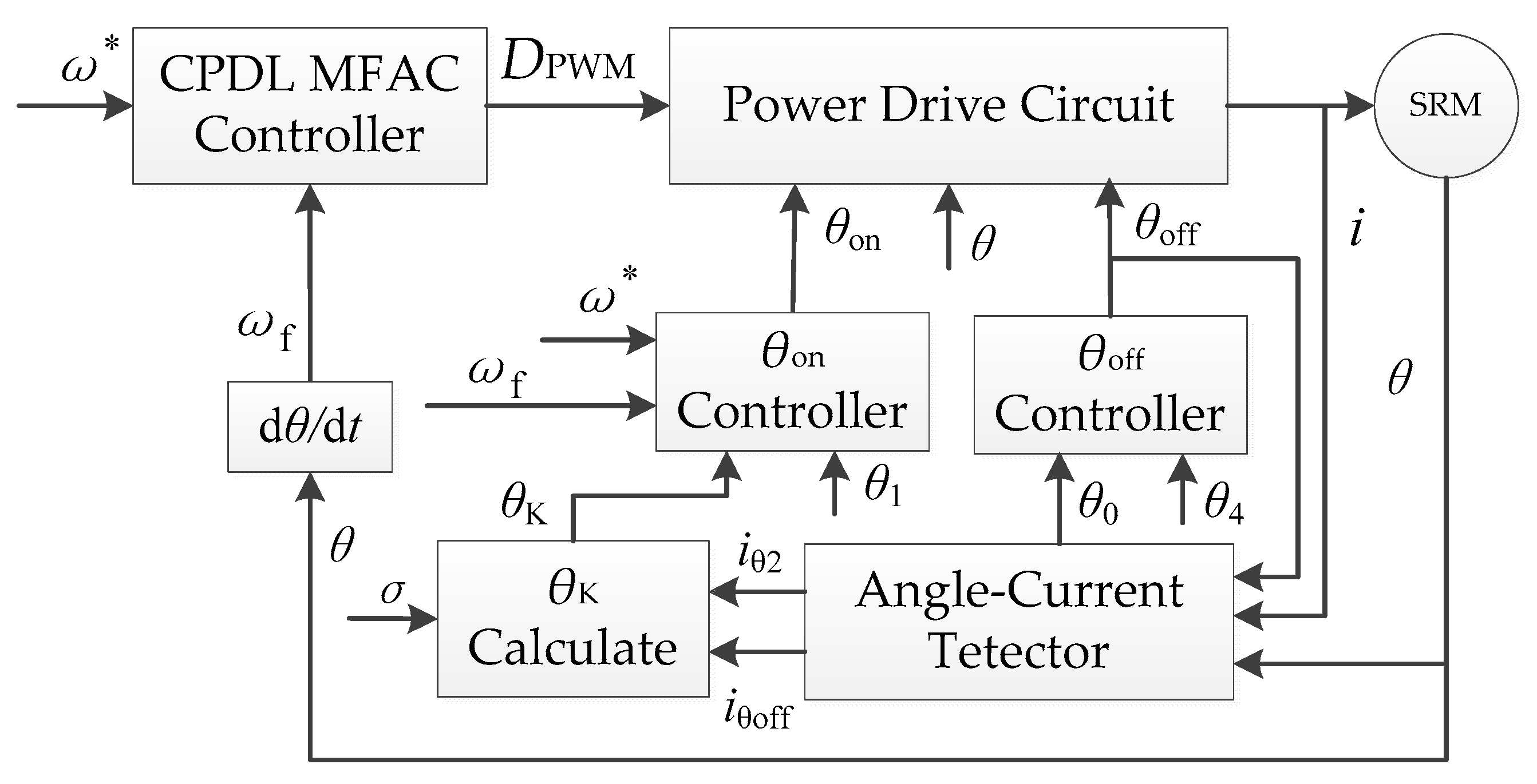
4. Control System Design

According to the above control algorithm, a closed-loop speed control system of switched reluctance motor is designed. The structure is shown in Figure 5, including power drive circuit, angle-current detector, CPDL MFAC controller, θK calculation module, θon controller and θoff controller.
The angle-current detector detects the rotor position angle θ and the current of the phase in real time, obtains the currents iθ2 and iθoff, and obtains the rotor position angle θ0 at the freewheeling zero point. The input of the CPDL MFAC controller is the target speed ω* and the feedback speed ωf, and the output voltage PWM duty cycle DPWM is calculated according to Equations (20) and (21). The input of the θon controller is the target speed ω* and the feedback speed ωf, and the turn-on angle θon is calculated according to Equation (14). The input of the θK calculation module is iθon, iθoff and the preset current difference σ, and θK is calculated according to Equation (13). The input of the θoff controller is θ0 and θ4, and the turn-off angle θoff is calculated according to Equation (15). The power drive circuit controls the operation of the switched reluctance motor according to DPWM, θon and θoff.
The CPDL MFAC controller is the outer loop of speed control. The motor speed can be adjusted in a wide range by adjusting the voltage PWM duty cycle, and the θon controller can only adjust the speed in a certain range. The control cycle of the CPDL MFAC controller is ten times or even dozens of times that of the θon controller. During the control cycle of the CPDL MFAC controller, the motor speed is adjusted by the θon controller. When the load or target speed increases too much, the output of the θon controller reaches θ1, and lost the speed control ability, then the system adjusts the motor speed by the CPDL MFAC controller, so that the θon controller exits saturation and restores the speed control ability. On the contrary, if the load or the target speed is greatly reduced, the output of the θon controller reaches θK, and the control ability of the speed is lost. The system also adjusts the speed of the motor through the CPDL MFAC controller, so that the θon controller exits saturation and resumes speed control capability.
In the speed control based on current chopping, there are two feedback control loops: the speed loop and the current loop. The control cycle of the current loop is the commutation cycle of the motor. Generally, the control period of the speed loop is much larger than that of the current loop. In the case of sudden large torque ripple, the torque output by the current of the motor is much smaller than the load torque, so that the speed of the motor drops rapidly, and the speed loop response is slow, and eventually there will be large speed fluctuations or even shutdown. Based on the APC control of PWM chopper, the output of the speed loop is the duty cycle of the voltage PWM, and the voltage PWM duty cycle is constant during a commutation period. When a sudden large torque pulsation occurs, the speed of the motor decreases rapidly, and the rotating electromotive force decreases, so that the average voltage of the motor is much larger than the rotating electromotive force. Due to the characteristics of the motor (voltage equation), the current of the winding increases rapidly, and the output torque also increases, which will suppress the sudden load torque pulsation in time.

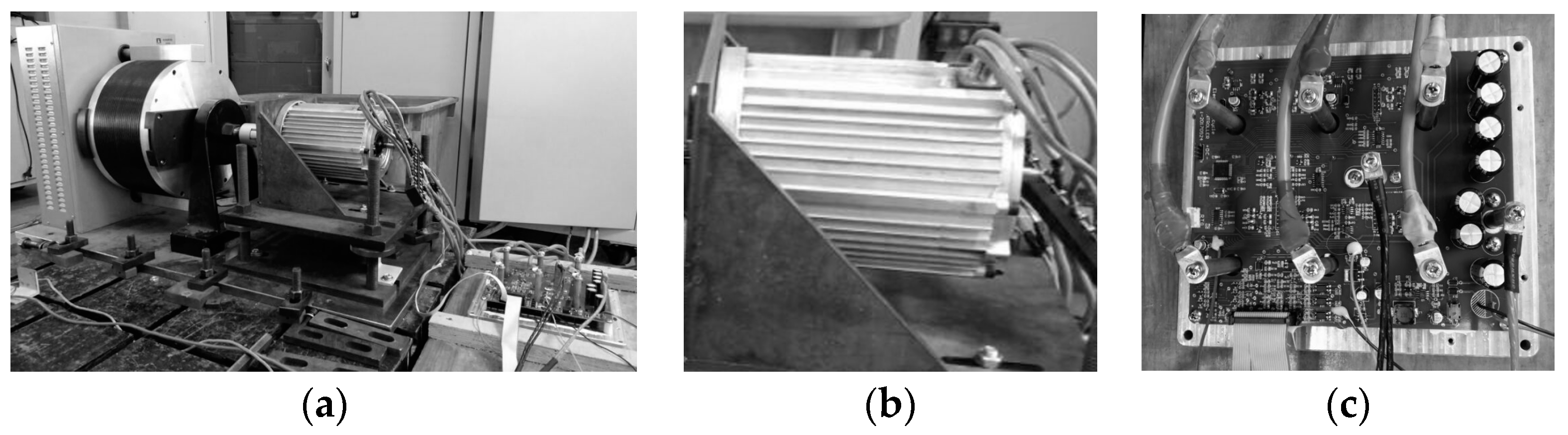
5. Experimental Test

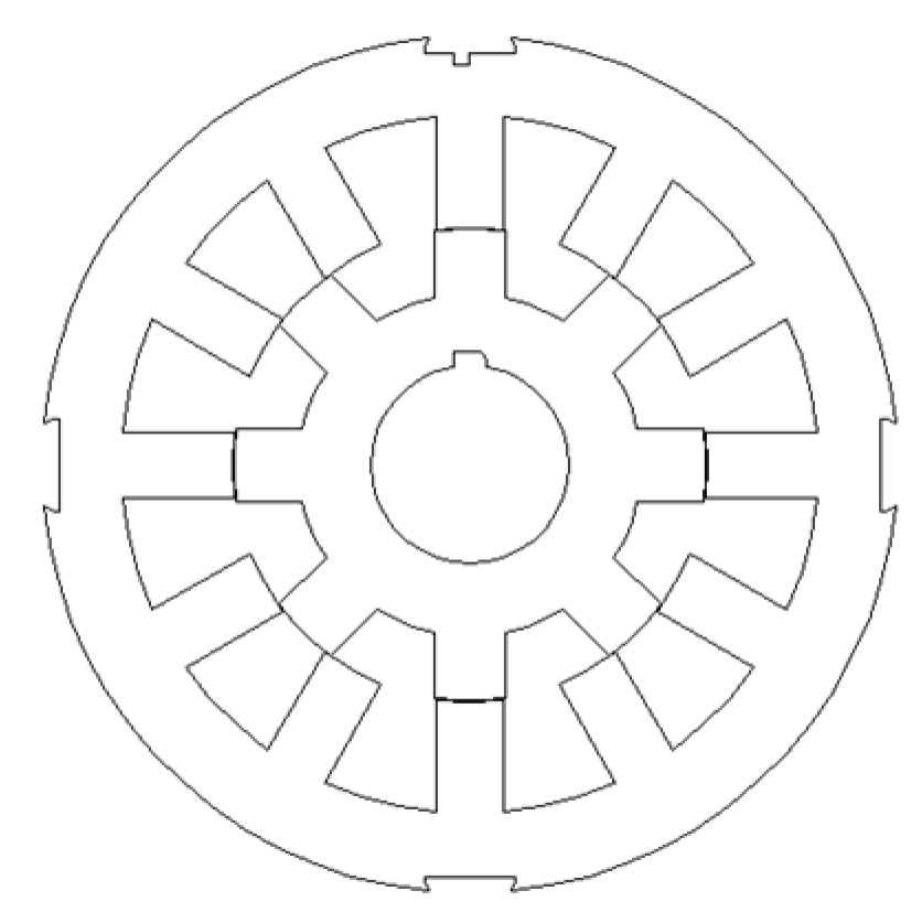
5.1. Experimental Prototype

In order to verify the feasibility of the proposed SRM speed control system based on the switching angle range, the power test is carried out for the 12/8 pole SRM with rated power of 3 KW, rated voltage of 60 V and rated speed of 3000 r/min. The experimental prototype is shown in Figure 6, in which Figure 6a is the field picture of the power test of the motor and control system; Figure 6b shows the measured SRM, and Figure 6c shows the designed SRM controller.
Figure 7 shows the stator and rotor cogging structure of the tested three-phase 12/8 pole SRM. The number of stator teeth is 12 and the number of rotor teeth is 8. Along the circumference of the air gap, the mechanical angle occupied by the stator teeth is 16°, the mechanical angle occupied by the stator slot is 14°, the mechanical angle occupied by the rotor teeth is 18°, and the mechanical angle occupied by the rotor slot is 27°.
Figure 8 shows the linear inductance curve of the one-phase winding of the motor. The horizontal axis is the electrical angle of the rotor relative to stator, and the vertical axis is the inductance value of the one-phase winding. The minimum inductance interval [θ1, θ2] is [−44°, 44°] and the electrical angle crossed is 88°, the inductance rise interval [θ2, θ3] is [44°, 172°] and the electrical angle crossed is 128°, the falling interval [θ4, θ5] is [188°, 316°] and the crossing electrical angle is also 128°, and the maximum inductance interval [θ3, θ4] is [172°, 188°] and the electrical angle crossed is 16°.

5.2. Speed Regulation Performance Experiment

The designed control algorithm is implemented on the control platform. Several key rotor position angles of the inductance model are given in Figure 8. θ1, θ2, θ3 and θ4 are −44°, 44°, 172° and 188°, respectively. It is given according to the structural size of the designed motor. The experiment verifies the proposed control strategy from the aspects of the turn-off angle, turn-on angle and speed control.

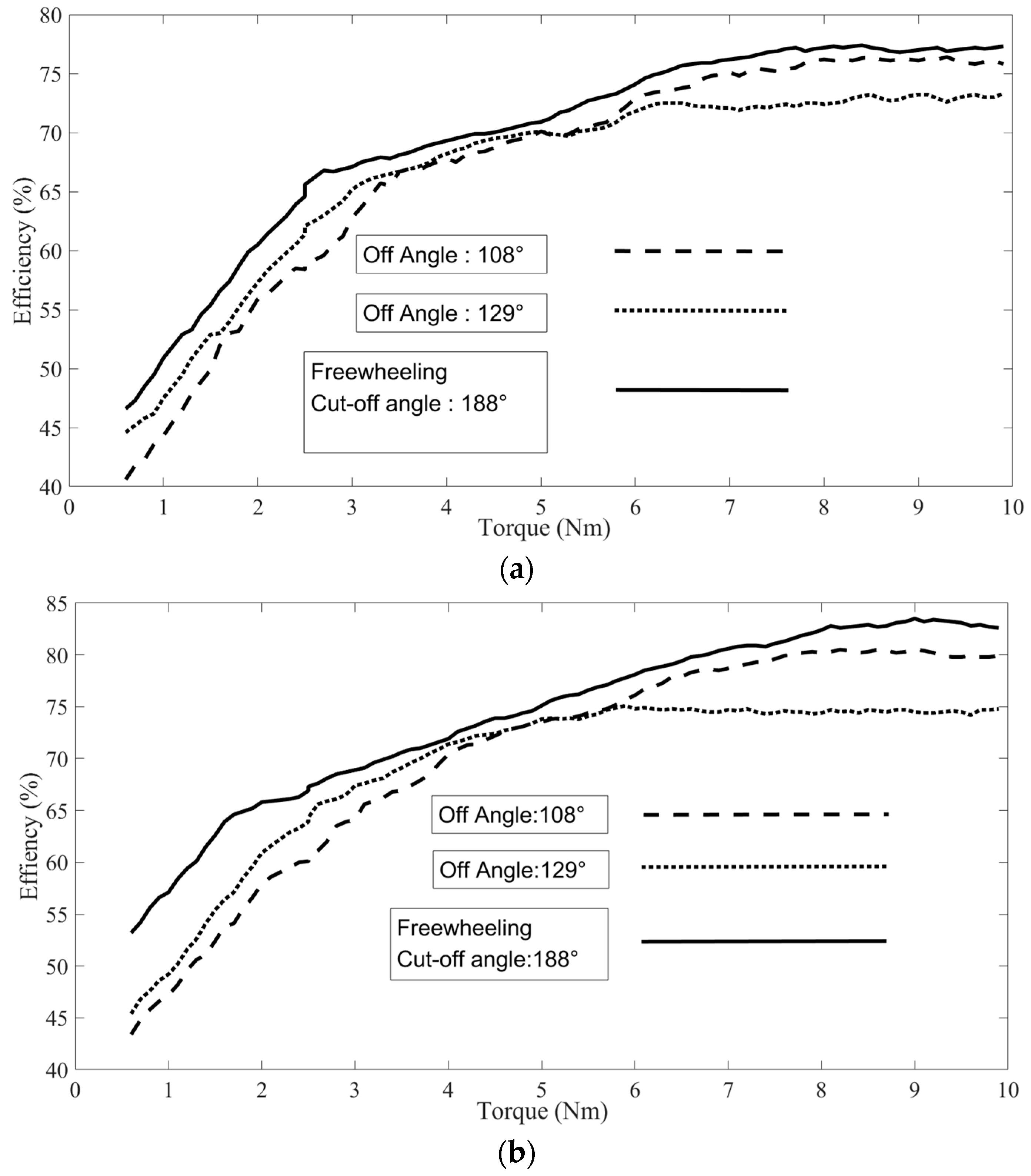
5.2.1. Control Test of Turn-Off Angle

The fixed turn-on angle θon is −10°, for different turn-off angles θoff; the PI control algorithm is adopted, and speed tracking control is realized by adjusting voltage PWM duty cycle DPWM. Set the turn-off angle θoff1 as 108° and θoff2 as 129°. Turn-off angle θoff3 is calculated according to Equation (13), and θ0 is set to θ4, which is 188°.
(1)
Efficiency comparison of different rotating speeds and shut-off angles
Control the motor speed at 1000 r/min, 2000 r/min and 3000 r/min, respectively, through the controller, gradually increase the resistance torque of the dynamometer to 8 N·m, and test the efficiency of the system at different speeds according to the set turn-off angle. Figure 9a shows the system efficiency when the turn-off angle is 108°, and Figure 9b shows the system efficiency when the turn-off angle is 129°. It can be seen that although the turn-off angle is different, the efficiency of the system increases with the increase in speed; on the other hand, for different motor speeds, the efficiency of the system increases with the increase in output power, which is in line with the general law of motor speed regulation with load, and also shows that the control strategy of turn-off angle is feasible.
(2)
Comparative test of different cut-off angles at the same speed
Figure 10 shows the efficiency test comparison curve with the speed of 2000 r/min and 3000 r/min, respectively, the off angle of 108°, 129° and the fixed freewheeling angle of 188°. It can be seen that at different speeds, the efficiency of the fixed freewheeling angle of 188° is the highest, which explains the effectiveness of the shut-off angle control based on the optimal freewheeling angle proposed in the text.
Under a light load, the efficiency of 108° turn-off angle is lower and the system efficiency of 129° turn-off angle is higher, while under a heavy load, the efficiency of 108° turn-off angle is higher, and the efficiency of 129° turn-off angle is higher system is less efficient. The reason is that under low load conditions, when the turn-off angle is 108°, the phase current of the motor is turned off earlier, and the rising area of the winding inductance is not fully utilized, so the efficiency is low. With the increase in load, the current also gradually increases. After the phase winding switch is turned off, the freewheeling time of the current gradually increases. The 108° turn-off angle allows the winding to have enough time for freewheeling, and the freewheeling current decreases to 0 near 188°, which does not produce negative torque and has high efficiency. For a larger phase winding current, when the turn-off angle is 129°, the freewheeling time is longer and the winding current has not fallen to 0 at 188°, so negative torque is generated and efficiency is reduced.

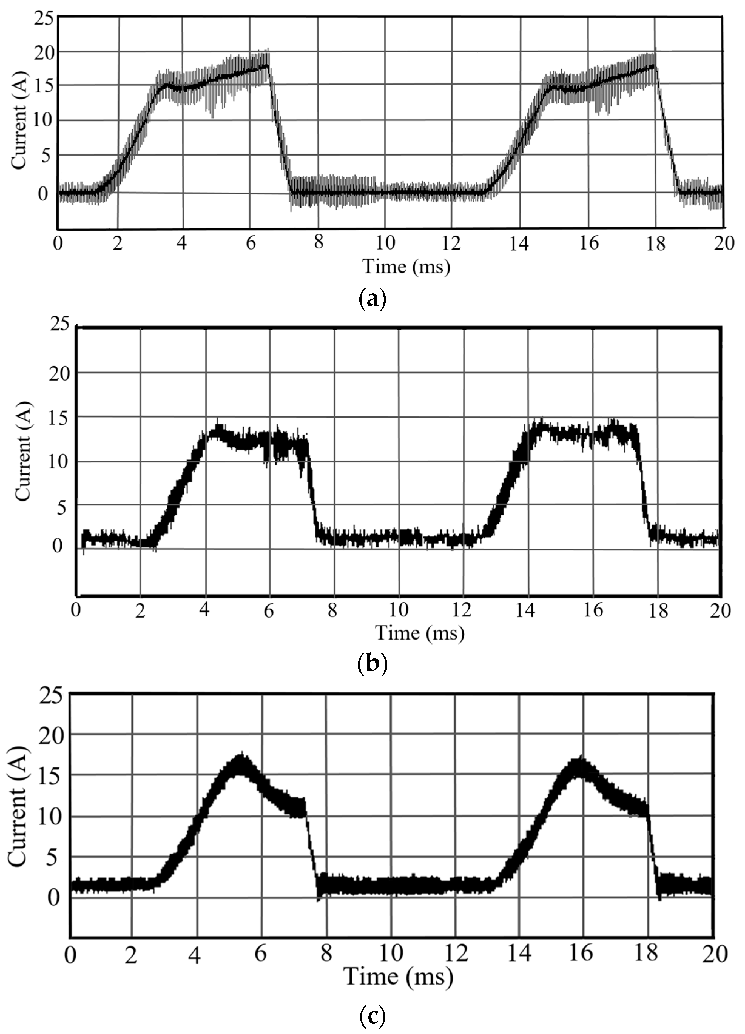
5.2.2. Control Test of Turn-On Angle

(1)
Current waveform test with fixed turn-on angle
Figure 11 shows the current waveforms when the motor speed is 800 r/min, the load torque is 6 N∙m, and the turn-on angles are 20°, 0°, and −20°, respectively. Figure 11a has a larger turn-on angle, the slope of the current in [θ2, θoff] is positive, and the average current value in the interval is about 16 A. Figure 11b shows the current waveform with the turn-on angle of 0, the slope of the current in [θ2, θoff] interval is approximately 0, and the average value of the current in this interval is about 12.5 A. Figure 11c shows the current waveform with the turn-on angle of −22°. The turn-on angle is small, the slope of the current in [θ2, θoff] interval is less than 0, and the average value of the current in this interval is about 13 A. Figure 11 shows that the magnitude of the turn-on angle determines the slope of the current in the interval [θ2, θoff]. As the turn-on angle decreases, the current slope changes from positive to negative. Giving the same load torque, if the turn-on angle is larger, the current is larger. The average current value with 0 and 20° turn-on angle is not much different. Therefore, it is beneficial that the slope of the current in the [θ2, θoff] interval is less than 0.
(2)
Tests with the same load torque and different rotational speeds
Figure 12 shows the current waveform at different speeds, and the turn-off angle θoff is set to 115°; the turn-on angle θoff controls according to the algorithm given in Equations (12)–(14). The σ of Equation (12) is set to 50% of the current peak, the load torque of the dynamometer is set to 8 Nm, and the traditional PI algorithm is used for speed control. Figure 12a shows the current waveform at the speed of 1000 r/min, Figure 12b shows the current waveform at the speed of 2000 r/min, and Figure 12c shows the current waveform at the speed of 3000 r/min.
In Figure 12, the current waveform under three different speed conditions meets the ideal current waveform, which shows that the ideal current waveform can be achieved through the control algorithm of the opening angle, and the opening angle control strategy proposed in this paper is effective.
(3)
Current waveforms with the same rotational speed and different load torques
Figure 13 shows the current waveforms when the rotational speed is 1500 r/min and the load torque is 4 N∙m, 8 N∙m, and 12 N∙m, respectively. The turn-on angle θon is controlled according to Equations (12)–(14), the turn-off angle is controlled according to Equation (15), and σ in Equation (12) is set to 2 A, and the model-free adaptive control algorithm is used for speed control. Figure 13a is the current waveform with the load torque of 4 N∙m. Figure 13b is the current waveform with the load torque of 8 N∙m. Figure 13c is the current waveform with the load torque of 12 N∙m. In Figure 13, the slope angle of the current waveform in the [θ2, θoff] interval increases with the increase in the load, indicating that the turn-on angle control strategy proposed in this paper is effective.

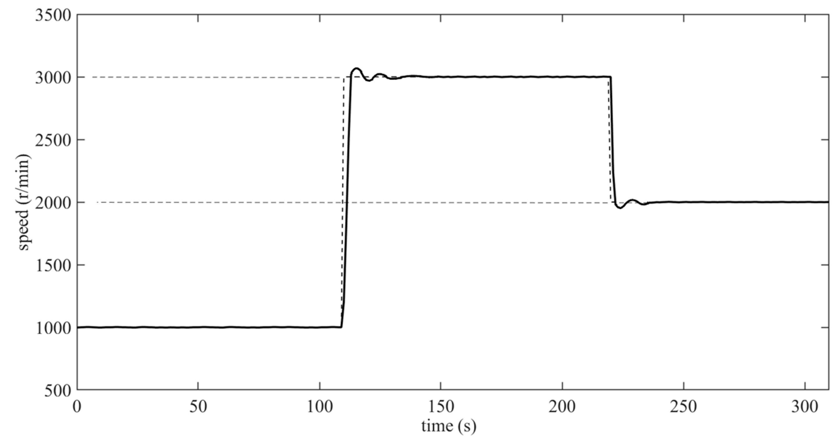
5.2.3. Speed Control Test

(1)
Constant torque load test
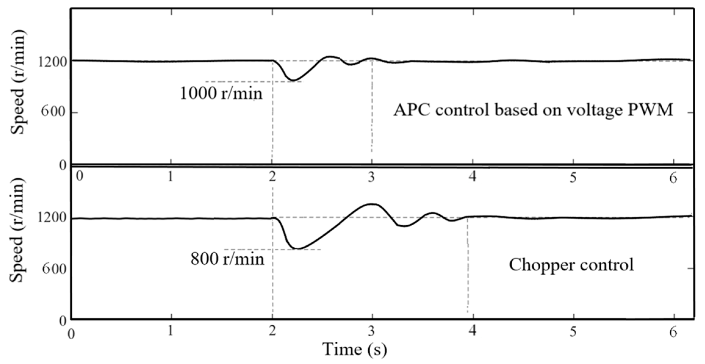
Set the dynamometer to apply a torque of 8 Nm, set σ as 2 A. The motor control strategy shown in Figure 5 is realized, and the tracking performance of the control algorithm is tested. The parameters of the model free adaptive control algorithm are set as: ϕ ^ c ( 1 ) = 0.5 , ε = 0.005, μ = 1, η = 1, ρ = 0.5, λ = 1.0. The tracking curve of speed is shown in Figure 14. First, make the motor run at a speed of 1000 r/min, then set the target speed to 3000 r/min, and the motor can complete the tracking of step speed regulation. Then, set the target speed to 2000 r/min, and the motor can also complete the speed regulation control of speed tracking.
(2)
Sudden Torque Test
The target speed is set to 1200 r/min, and the switch reluctance motor control strategy proposed in Figure 5 is adopted. The load torque is set as 4 N∙m at first, and then 12 N∙m is suddenly added. Figure 15 shows the current waveform during speed tracking. Figure 15a shows the current waveform of APC speed control based on switching angle. A load torque of 12 N∙m is suddenly applied at about 4 s, and the current increases rapidly. Figure 15b shows the current waveform of the speed control method based on current chopping. The load torque of 12 N∙m is suddenly applied at about 2 s, and the current increases after nearly 500 ms later. This shows that the APC speed control based on the switching angle proposed in this paper can quickly suppress the change in the load torque and has advantages under the load with sudden large pulsation.
Figure 16 is a graph of the speed change corresponding to the two control methods in Figure 15. The upper part of Figure 16 is the speed change curve of the APC speed regulation control method, and the lower part is the speed change curve of the current chopping control speed regulation method. It can be seen that the APC speed control method above has a smaller speed reduction (200 r/min) and a shorter speed recovery time (1 s), while the current chopping speed control method below has a larger speed drop (400 r/min), and the speed longer recovery time (2 s). It also shows that the control strategy proposed in this paper has advantages for a sudden large-pulse load.

5.3. Test Conclusion

For the switched reluctance motor, the turn-off angle efficiency comparison test, the turn-on angle current waveform test, the speed tracking test, and the speed tracking comparison test under sudden heavy load conditions are carried out. The test results show that the speed control strategy of the switched reluctance motor based on the switching angle interval proposed in this paper is feasible.

6. Conclusions

In this paper, through the analysis of the linear inductance model of the switched reluctance motor, combined with the nonlinear inductance model obtained by electromagnetic simulation, a control strategy that does not depend on the accurate motor model is designed. In terms of the switch reluctance motor control strategy, the turn-off angle control algorithm based on the optimal freewheeling zero point, the turn-on angle control algorithm based on the optimized current waveform and the voltage PWM speed control algorithm for switched reluctance motor based on model-free adaptive control are designed, respectively. Through the separate design of the control strategies for the three key parameters, the degree of coupling among them is greatly reduced, the control algorithm is simplified and easy to implement. Analysis and experiments show that the control strategy proposed in this paper can realize the speed tracking control of the switched reluctance motor, especially suitable for the load with sudden large torque ripple.

Author Contributions

Algorithm design, Y.Z.; algorithm design, Y.Z.; coding and testing, E.H. and L.C.; design and manufacture of control system, Z.W. and Y.Z.; article review and proofreading, Z.W. and L.C.; funding acquisition, Y.Z. All authors have read and agreed to the published version of the manuscript.

Funding

This work was supported by the Science and Technology Major Project of Inner Mongolia Autonomous Region (2020ZD0014).

Institutional Review Board Statement

Not applicable.

Informed Consent Statement

Not applicable.

Data Availability Statement

All important data are included in the manuscript.

Acknowledgments

Thank the School of Rail Transportation of Shandong Jiaotong University for providing experimental equipment and experimental testing help.

Conflicts of Interest

The authors declare no conflict of interest.

References

  1. Bilgin, B.; Howey, B.; Callegaro, A.D.; Liang, J.; Kordic, M.; Taylor, J.; Emadi, A. Making the Case for Switched Reluctance Motors for Propulsion Applications. IEEE Trans. Veh. Technol. 2020, 69, 7172–7186. [Google Scholar] [CrossRef]
  2. Bieńkowski, K.; Łapczyński, S.; Szulborski, M.; Kozarek, Ł.; Gołota, K.; Cichecki, H.; Kolimas, Ł.; Żelaziński, T.; Smolarczyk, A.; Babiński, A.; et al. Validated Analytical Model of 8/6 and 10/8 Switched Reluctance Motors. Energies 2022, 15, 630. [Google Scholar] [CrossRef]
  3. Lan, Y.; Benomar, Y.; Deepak, K.; Aksoz, A.; Baghdadi, M.; Bostanci, E.; Hegazy, O. Switched Reluctance Motors and Drive Systems for Electric Vehicle Powertrains: State of the Art Analysis and Future Trends. Energies 2021, 14, 2079. [Google Scholar] [CrossRef]
  4. Valencia, D.F.; Tarvirdilu-Asl, R.; Garcia, C.; Rodriguez, J.; Emadi, A. A Review of Predictive Control Techniques for Switched Reluctance Machine Drives. Part I: Fundamentals and Current Control. IEEE Trans. Energy Convers. 2020, 36, 1313–1322. [Google Scholar] [CrossRef]
  5. Valencia, D.F.; Tarvirdilu-Asl, R.; Garcia, C.; Rodriguez, J.; Emadi, A. A Review of Predictive Control Techniques for Switched Reluctance Machine Drives. Part II: Torque Control, Assessment and Challenges. IEEE Trans. Energy Convers. 2020, 36, 1323–1335. [Google Scholar] [CrossRef]
  6. Sun, X.; Diao, K.; Lei, G.; Guo, Y.; Zhu, J. Direct Torque Control Based on a Fast Modeling Method for a Segmented-Rotor Switched Reluctance Motor in HEV Application. IEEE J. Emerg. Sel. Top. Power Electron. 2019, 9, 232–241. [Google Scholar] [CrossRef]
  7. Zhang, M.; Ali, N.; Gao, Q. Winding inductance and performance prediction of a switched reluctance motor with an exterior-rotor considering the magnetic saturation. CES Trans. Electr. Mach. Syst. 2021, 5, 212–223. [Google Scholar] [CrossRef]
  8. Evangeline, S.J.; Kumar, S.S.; Jayakumar, J. Torque modeling of Switched Reluctance Motor using LSSVM-DE. Neurocomputing 2016, 211, 117–128. [Google Scholar] [CrossRef]
  9. Li, Z.; Wei, X.; Wang, J.; Liu, L.; Du, S.; Guo, X.; Sun, H. Design of a Deflection Switched Reluctance Motor Control System Based on a Flexible Neural Network. Energies 2022, 15, 4172. [Google Scholar] [CrossRef]
  10. Sun, Q.; Wu, J.; Gan, C. Optimized Direct Instantaneous Torque Control for SRMs With Efficiency Improvement. IEEE Trans. Ind. Electron. 2020, 68, 2072–2082. [Google Scholar] [CrossRef]
  11. Wang, X.; Palka, R.; Wardach, M. Nonlinear Digital Simulation Models of Switched Reluctance Motor Drive. Energies 2020, 13, 6715. [Google Scholar] [CrossRef]
  12. Song, X.; Zhu, J.; Ren, P.; Lv, X. An Improved Fuzzy Control for Switched Reluctance Motor Based on Torque Sharing Function. In Proceedings of the 2021 6th International Conference on Automation, Control and Robotics Engineering (CACRE), Dalian, China, 15–17 July 2021; pp. 119–123. [Google Scholar] [CrossRef]
  13. Mahalakshmi, G.; Kanthalakshmi, S. Design of Iterative Learning Controller for Switched Reluctance Motor with Least Torque Ripple. In Proceedings of the 2022 8th International Conference on Advanced Computing and Communication Systems, Coimbatore, India, 25–26 March 2022; Volume 1, pp. 299–304. [Google Scholar] [CrossRef]
  14. Sun, X.; Feng, L.; Diao, K.; Yang, Z. An Improved Direct Instantaneous Torque Control Based on Adaptive Terminal Sliding Mode for a Segmented-Rotor SRM. IEEE Trans. Ind. Electron. 2020, 68, 10569–10579. [Google Scholar] [CrossRef]
  15. Dhale, S.; Nahid-Mobarakeh, B.; Emadi, A. A Review of Fixed Switching Frequency Current Control Techniques for Switched Reluctance Machines. IEEE Access 2021, 9, 39375–39391. [Google Scholar] [CrossRef]
  16. Nugroho, A.A.; Khosyi’in, M.; Arifin, B.; Suprapto, B.Y.; Haddin, M.; Nawawi, Z. Load Effect on Switched Reluctance Motor Using Hysteresis Current and Voltage Control. In Proceedings of the 2021 8th International Conference on Electrical Engineering, Computer Science and Informatics (EECSI), Semarang, Indonesia, 20–21 October 2021; pp. 59–63. [Google Scholar] [CrossRef]
  17. Bober, P.; Ferkova, Z. Online Optimization of Firing Angles for Switched Reluctance Motor Control. In Proceedings of the 2021 International Conference on Electrical Drives & Power Electronics (EDPE), Dubrovnik, Croatia, 22–24 September 2021; pp. 238–242. [Google Scholar] [CrossRef]
  18. Fang, G.; Scalcon, F.P.; Xiao, D.; Vieira, R.P.; Grundling, H.A.; Emadi, A. Advanced Control of Switched Reluctance Motors (SRMs): A Review on Current Regulation, Torque Control and Vibration Suppression. IEEE Open J. Ind. Electron. Soc. 2021, 2, 280–301. [Google Scholar] [CrossRef]
  19. Hadapad, B.S.; Naik, R.L. An Investigation on Torque Control Strategies for Switched Reluctance Motor. In Proceedings of the 2021 5th International Conference on Electrical, Electronics, Communication, Computer Technologies and Optimization Techniques (ICEECCOT), Mysuru, India, 10–11 December 2021; pp. 161–167. [Google Scholar] [CrossRef]
  20. Fang, G.; Bauman, J. Optimized Switching Angle-based Torque Control of Switched Reluctance Machines for Electric Vehicles. In Proceedings of the 2020 IEEE Transportation Electrification Conference & Expo (ITEC), Chicago, IL, USA, 23–26 June 2020; pp. 186–191. [Google Scholar] [CrossRef]
  21. Patel, M.A.; Patel, R.A.; Sharma, U.R. Advance Angle Control Based In-wheel Switched Reluctance Motor for EV Propulsion System. In Proceedings of the 2021 Asian Conference on Innovation in Technology (ASIANCON), Pune, India, 28–29 August 2021; pp. 1–6. [Google Scholar] [CrossRef]
  22. Sah, G.K.; Jagwani, S.; Venkatesha, L. A new simplified control strategy for switched reluctance motor. In Proceedings of the 2017 Recent Developments in Control, Automation & Power Engineering (RDCAPE), Noida, India, 26–26 October 2017; pp. 241–244. [Google Scholar] [CrossRef]
  23. Ahmad, S.S.; Narayanan, G. Linearised modelling of switched reluctance motor for closed loop current control. In Proceedings of the 2014 IEEE 6th India International Conference on Power Electronics (IICPE), Kurukshetra, India, 8–10 December 2014; pp. 1–6. [Google Scholar] [CrossRef]
  24. Verma, A.; Ahmad, S.S.; Narayanan, G. Optimal Switching Angles for Single-Pulse-Operated Switched Reluctance Generator. In Proceedings of the 2021 National Power Electronics Conference (NPEC), Bhubaneswar, India, 15–17 December 2021; pp. 1–6. [Google Scholar] [CrossRef]
  25. Sologubov, A.Y.; Kirpichnikova, I.M. Switched-Reluctance Drive with Sigmoids-Based Pulse-Phase Control. In Proceedings of the 2021 International Conference on Electrotechnical Complexes and Systems (ICOECS), Ufa, Russia, 26–29 October 2021; pp. 209–213. [Google Scholar] [CrossRef]
  26. Hou, Z.; Jin, S. Model Free Adaptive Control: Theory and Applications; CRC Press: Boca Raton, FL, USA, 2013. [Google Scholar]
  27. Liu, S.; Hou, Z.; Tian, T.; Deng, Z.; Guo, L. Path tracking control of a self-driving wheel excavator via an enhanced data-driven model-free adaptive control approach. IET Control Theory Appl. 2020, 14, 220–232. [Google Scholar] [CrossRef]
  28. Liao, Y.; Jiang, Q.; Du, T.; Jiang, W. Redefined Output Model-Free Adaptive Control Method and Unmanned Surface Vehicle Heading Control. IEEE J. Ocean. Eng. A J. Devoted Appl. Electr. Electron. Eng. Ocean. Environ. 2019, 45, 714–723. [Google Scholar] [CrossRef]
  29. Lei, T.; Hou, Z.; Ren, Y. Data-Driven Model Free Adaptive Perimeter Control for Multi-Region Urban Traffic Networks With Route Choice. IEEE Trans. Intell. Transp. Syst. 2019, 21, 2894–2905. [Google Scholar] [CrossRef]
  30. Zhao, Y.; Yuan, Z.; Lu, C.; Zhang, G.; Li, X.; Chen, Y. Improved model-free adaptive wide-area coordination damping controller for multiple-input–multiple-output power systems. IET Gener. Transm. Distrib. 2016, 10, 3264–3275. [Google Scholar] [CrossRef]
  31. Hashjin, S.A.; Pang, S.; Miliani, E.-H.; Ait-Abderrahim, K.; Nahid-Mobarakeh, B. Data-Driven Model-Free Adaptive Current Control of a Wound Rotor Synchronous Machine Drive System. IEEE Trans. Transp. Electrif. 2020, 6, 1146–1156. [Google Scholar] [CrossRef]
  32. Masood, R.J.; Wang, D.B.; Ali, Z.A.; Khan, B. DDC Control Techniques for Three-Phase BLDC Motor Position Control. Algorithms 2017, 10, 110. [Google Scholar] [CrossRef]
  33. Hou, Z.; Jin, S. A Novel Data-Driven Control Approach for a Class of Discrete-Time Nonlinear Systems. IEEE Trans. Control. Syst. Technol. 2011, 19, 1549–1558. [Google Scholar] [CrossRef]
  34. Hou, Z.; Chi, R.; Gao, H. An Overview of Dynamic-Linearization-Based Data-Driven Control and Applications. IEEE Trans. Ind. Electron. 2017, 64, 4076–4090. [Google Scholar] [CrossRef]
Figure 1. SRM linear inductance and APC control current curve.
Energies 15 05782 g001
Figure 2. Current waveform of linear inductance model with different turn-on angles.
Energies 15 05782 g002
Figure 3. Current waveforms at different turn-on angles.
Energies 15 05782 g003
Figure 4. Inductance curve of SRM winding under different currents.
Energies 15 05782 g004
Figure 5. Closed-loop speed control system of switched reluctance motor.
Energies 15 05782 g005
Figure 6. Control system of reluctance switch prototype. (a) Power test of SRM. (b) Tested motor. (c) Motor controller.
Energies 15 05782 g006
Figure 7. Stator and rotor cogging structure of SRM.
Energies 15 05782 g007
Figure 8. Linear inductance curve of three phase 12/8 pole SRM.
Energies 15 05782 g008
Figure 9. Efficiency test of different rotating speeds and shut-off angles. (a) Efficiency comparison of different rotating speeds when the turning off angle is 108°. (b) Efficiency comparison of different rotating speeds with a turning-off angle of 129°.
Energies 15 05782 g009
Figure 10. Efficiency comparison of the same speed and different cut-off angles. (a) 2000 r/min, efficiency comparison of different cut-off angles. (b) 3000 r/min, efficiency comparison of different cut-off angles.
Energies 15 05782 g010
Figure 11. Current waveforms of different turn-on angles. (a) Current waveform with turn-on angle of 20°. (b) Current waveform with turn-on angle of 0°. (c) Current waveform with turn-on angle of −20°.
Energies 15 05782 g011
Figure 12. Current waveform of opening angle control at different speeds. (a) Current waveform at 1000 r/min. (b) Current waveform at 2000 r/min. (c) Current waveform at 3000 r/min.
Energies 15 05782 g012
Figure 13. Current waveforms with same rotational speed and different load torques. (a) Current waveform with 4 N∙m load torque. (b) Current waveform with 8 N∙m load torque. (c) Current waveform with 12 N∙m load torque.
Energies 15 05782 g013
Figure 14. PWM speed regulation control based on the optimal range of switching angle.
Energies 15 05782 g014
Figure 15. Comparison of current waveforms for sudden increase in torque. (a) Current waveform of APC speed control based on switching angle. (b) Current waveform based on current chopping speed control.
Energies 15 05782 g015
Figure 16. Comparison of the speed transition process with sudden torque increase.
Energies 15 05782 g016
Publisher’s Note: MDPI stays neutral with regard to jurisdictional claims in published maps and institutional affiliations.

