1. Introduction
The targets that have been set by the European Commission regarding the mitigation of greenhouse gas emissions in the long-term for 2050 and especially in the short-term for 2030, have already started impacting numerous sectors due to the new legislations that have been applied towards this direction. Such sectors include, but are not limited to, the transportation, the energy/electricity supply, and the manufacturing sectors [
1]. The transportation sector, consisting of road vehicles, aviation, and shipping, is responsible for approximately 16% of the world’s greenhouse gases [
2]. The increase in road vehicles that are powered by diesel engines has led to the degradation of the air quality in concentrated traffic zones, urban regions, industrial regions, as well as in rural regions, according to the results reported for particulate matter (PM) [
3] and NOx [
4] emissions.
The engine manufacturers of the transportation sector face, for the first time, a design challenge, since they must achieve a significant reduction in engine emissions while at the same time having to improve, or at least maintain, thermal efficiency and fuel economy [
5]. A zero-emission alternative is the use of an electric motor instead of an internal combustion (IC) engine. The electric motor may be powered either by a battery or fuel cells with the electrochemical reaction of hydrogen (H
2) fuel. Regarding battery-operated vehicles, it is very difficult to meet all needs concerning personal mobility, heavy-duty vehicles, special-use vehicles, off-road vehicles, sustainability, and feasibility [
6]. On the other hand, even though fuel cell technology is considered to be the cleanest and most efficient way of using H
2, it cannot be adopted to tackle the short-term challenges because technology improvements are required to reduce its cost and size [
7]. Therefore, it is of great importance to improve exhaust emission characteristics and the thermal efficiency of the existing technology of IC engines since our dependence on them will not end anytime soon [
8].
The use of alternative fuels with reduced emissions in IC engines, either of spark ignition (SI) or compression ignition (CI) technology, is considered a convenient transitional or long-term solution in some cases. Among various alternative fuels, H
2 is considered an attractive choice due to the technological advancements in both IC engines and H
2 production from renewable energy sources [
9], e.g., using electrolysis. Even though H
2 production by water electrolysis is the most energy consuming method compared to other methods [
9,
10], electrolysis is considered an emission-free process when the electricity that is required is produced by renewable energy sources.
Other attractive advantages of H
2 include its abundancy in nature, it has zero carbon content, and its lower heating value per unit mass is more than 2.5 times larger than gasoline and diesel fuels. As a result, and due to the universal applicability of H
2 for the energy needs of several sectors, investments and developments in the renewable energy sector are rapidly increasing [
6]. However, there are important challenges that must be overcome to allow the use of H
2 for long-distance road trips, marine applications, and aviation. Adequate quantities of H
2 in such applications require very complex and expensive H
2 storage facilities because of its very low density, which is equal to 0.089 kg/m
3 at atmospheric pressure. H
2 can be physically stored in gas bottles with ultra-high pressure or in liquid form that requires ultra-low temperatures; however, both suffer from safety issues. The former is quite dangerous, while the latter would consume about 30% of hydrogen’s total energy content [
6] to maintain it at the required low temperature level.
1.1. Combustion of H2 in ICE as a Sole Fuel
As long as the H
2 storage and supply chain challenges are overcome, IC engines could continue to play an important role in the future of the transportation sector, provided that H
2 production would be emission free (e.g., using solar and/or wind energy) and cost effective. This would be an ideal solution for the transportation sector and the IC engine manufacturers, since all the technological advances on IC engines that have been achieved through the years will remain useful, taking advantage of their reliability, durability, existing supply chain, as well as the existing manufacturing and recycling infrastructure [
6].
Nevertheless, engine manufacturers are required to re-design part of the engine or adapt an engine’s operation due to the distinct characteristics of H
2. First, an existing engine that is modified for a H
2 operation might produce a lower power output, since the very low density of H
2 results in a reduced energy density of the H
2–air mixture that is fed into the cylinders of the engine [
9]. In addition, the low flammability limit of H
2 (4%), in combination with its high diffusivity and significantly increased combustion velocity, favors a lean-mixture operation with improved combustion stability [
11,
12]. The high diffusivity of H
2 also contributes to a decrease in the heterogeneity of the diesel fuel spray, forming a more uniform combustible mixture [
13]. Furthermore, the improved efficiency of the engine can be theoretically achieved, due to the high auto-ignition temperature of H
2 (571 °C) that allows increased compression ratio (CR) values. On the other hand, the wide flammability limit of H
2 (4–74%) in combination with its low minimum ignition energy can easily lead to pre-ignition, resulting in knocking [
9] and therefore instability and efficiency reduction.
Between SI and CI engines, the sole combustion of H
2 is technically feasible only in SI engines [
9,
14,
15], since an extremely high compression ratio is needed to reach the high auto-ignition temperature of H
2 in CI engines. Therefore, H
2 can be used in CI engines only with the presence of an ignition source. Even though the applicability/suitability of SI engines for the sole combustion of H
2 has been demonstrated by many researchers [
16,
17,
18], several drawbacks have arisen. These include a 30% reduction in Brake Thermal Efficiency (BTE), pre-ignition events, flashback/backfire events, as well as unstable operation and knocking at high loads, whilst an increase in the CR to mitigate brake power reduction would enhance knocking [
4,
7,
9,
11].
1.2. Dual Fuel ICE
Both SI and CI engines have been studied for dual fuel operations, using H
2-enriched air, in order to improve the performance and the emission characteristics of the base engine that runs only with the main fuel, i.e., gasoline [
19,
20,
21,
22] and diesel, respectively. In the case of CI engines, the ignition of H
2 is provided by a pilot diesel injection, regardless of the implemented H
2 injection method [
4].
The improvement of the performance and emission characteristics of CI diesel engines would be more beneficial than SI engines, due to their capability to run with higher compression ratios, leaner fuel–air ratios, and a lower throttling loss, that enhances thermal efficiency [
8,
23,
24]. Moreover, CI engines have lower Carbon Dioxide (CO
2) emissions per km or kWh, compared to SI engines [
8]. However, CI engines have the disadvantages of increased Nitrogen-Oxides (NOx), Smoke, and PM emissions [
4,
8,
25,
26] that need to be tackled in the short-term to achieve their survivability, due to the increasingly stringent emissions legislation. The use of a secondary fumigated fuel can affect the performance and the emission characteristics of a CI diesel engine, as demonstrated by [
23], where the effect of fumigated H
2, ethanol, and gasoline addition was investigated using different diesel injection timings to control the ignition. Compared to other fuels, H
2 provides fewer cyclic variations, a smoother engine performance, better emission characteristics (due to the zero-carbon content and ability to run with high amount of excess air), and improved efficiency [
11,
27]. The improved efficiency of a lean mixture operation is favored by the heat transfer characteristics of H
2 that lead to high compression temperatures [
28]. At high loads though, with hydrogen-rich conditions, the performance of the dual fuel operation is restricted because of knocking. The knock-free operation of an engine can be extended by injecting water inside the cylinder to provide cooling and mitigate the sharp increase in temperatures [
9].
1.3. Emission Reduction Techniques of Diesel Engines
Current technology of four-stroke diesel engines incorporates costly after-treatment systems, such as selective catalytic reduction (SCR), lean NOx-trap (LNT), diesel particulate filter (DPF), etc., to achieve NOx and PM reduction at acceptable regulated levels [
3]. However, the further reduction in emissions at the levels of the future goals that have been set by the European Commission requires more effective systems and techniques. It is very important though that any new technique or system not only meets the emission requirements but can also be adapted easily without the need for radical changes on the existing conventional diesel engine [
5]. To this end, the use of H
2 in the intake air of diesel engines has been proven to be a very attractive technique for the reduction in PM, unburned hydrocarbons (UHC), NOx, Carbon Monoxide (CO), and CO
2. Such a solution may also eliminate the need for urea/ammonia (NH
3) storage in tanks that comes with the risk of ammonia slip in the exhaust pipe [
6] which increases the toxicity of the exhaust gases. The induction of H
2 alone, without tuning other parameters of the engine, may lead to adverse results and a significant increase in several emission components [
5,
9]. The combination of H
2 and SCR in CI engines was investigated by the authors of [
29], who demonstrated that such a combination is promising to reduce NOx emissions. Several studies have examined the effect of H
2 induction in combination with the use of Exhaust Gas Recirculation (EGR) in diesel engines in order to achieve the simultaneous reduction in both NOx, Smoke, and PM emissions [
24], since a large quantity of H
2 may result in significantly increased NOx emissions because of the higher temperatures formed inside the engine cylinders. Using EGR without H
2 induction reduces NOx emissions; however, all other emission gases increase [
30]. A trade-off study was performed by the authors of [
31], presenting a successful combination of EGR and H
2 induction where Smoke and NOx emissions were simultaneously reduced, compared to the diesel-only operation. Other studies showed that the use of H
2 can reduce NOx emissions at a low temperature and heavy EGR conditions [
32,
33].
1.4. Contradictory Results in the Experimental Literature
Numerous studies have been conducted during the last years/decades that have investigated the dual H
2–diesel fuel operation of four-stroke CI engines. Even though some conclusions/results are clear and consistent among the studies, apart from limited works, there are also contradictory results that need to be investigated further. In particular, contradictory results were reported in the case of NOx and PM emissions at high engine loads [
34]. Only a few studies identified that UHC, NOx, and PM can be all together reduced [
9], while most of the reported results concluded that it is not possible to reduce all emission gases at the same time [
35]. No clear and consistent effect on NOx emissions and brake efficiency was reported, since both were found to either increase or decrease according to the operating point of the engine and the H
2 concentration [
36,
37]. Regarding the effect of H
2 addition on the emission characteristics, most studies reported a decrease in CO, CO
2, and Smoke, and an increase in NOx [
38]. On the other hand, the reported effect of H
2 addition on the performance parameters such as BTE, Brake Specific Fuel Consumption (BSFC), and in-cylinder pressure, varied among the studies. An overview of the experimental studies on the effect of H
2 induction in diesel engines was given by the authors of [
9], demonstrating the contradictory conclusions among the studies through a tabulated presentation. However, the comparison of the reported results and conclusions is not a trivial task because of the differences in the experimental configuration, the engines’ characteristics, and the engines’ operational parameters that were used in each study [
38]. Important parameters that might affect the results of an experiment include, but are not limited to, the diesel fuel injection pressure, the injection timing of diesel, the H
2 energy share (HES), the H
2 induction method and location, the injection timing of H
2, the EGR ratio and temperature (cooled or hot), the CR, the load range examined, and the engine speed.
The present study gathers the characteristics of the engines and important operational parameters used in different experimental studies on four-stroke CI engines operated with dual H
2–diesel fuel. This collection has been proven to be very useful when comparing results between studies, since common and different parameters can easily be identified. Therefore, the evaluation of deviations between conclusions can be discussed in conjunction with parameters that might significantly influence the results. In addition, an introduction to the HYMAR project is given in
Section 4, by presenting the experimental configuration of a heavy-duty auxiliary generator-set (Genset) engine, and the modifications that were performed to install the required instrumentation. The purpose of the HYMAR project is to test the utilization of a H
2 production unit for on-board use in the maritime sector.
2. Hydrogen Induction Techniques
H
2 can be inducted into an engine’s cylinders using one out of the following four techniques, or even a combination of them [
11]. The simplest technique is Carburation, where H
2 is inducted before the throttling valve. Even though Carburation is the simplest method for inducting H
2, it is not used in modern studies because it enhances the occurrence of backfire. Thus, Carburation has been proved to be an inappropriate technique for inducting H
2 [
4].
The most widely used technique for H
2 induction in diesel engines is the Continuous Manifold Injection (CMI), where H
2 is injected directly into the intake manifold through an injector/port. Compared to Carburation, CMI reduces the problem of backfire significantly, while the simplicity of the method is maintained. A more complicated technique is the Timed Port Injection (TPI), which can eliminate completely the occurrence of backfire, since the injection of H
2 can be adjusted to start after the opening of the intake valve. Such an adjustment allows for the cylinder inner walls to cool down and combustion residuals to dilute, thus reducing the pre-ignition sources [
4,
31]. However, TPI suffers from incomplete mixing of H
2–air due to the close distance of H
2 injection to the cylinder’s intake port. At the same time, TPI requires a dedicated H
2 injector for each cylinder that must be adjusted separately. Comparing the Carburation, CMI, and TPI techniques, it was found that TPI provides better results regarding both efficiency and emission characteristics [
9,
39,
40,
41]. In addition to the CMI and TPI, one can find in the literature the Timed Manifold Injection (TMI) method [
7], which, however, is not suitable for multi-cylinder engines since it would be very difficult to set multiple injection timings according to the inlet valve opening of each cylinder and ensuring, at the same time, that the injected quantity of H
2 is delivered to the correct cylinder. Even though one can find studies in the literature with multi-cylinder engines that may adjust H
2 injection frequency and the duration of a single point manifold injector [
42], this is used to control the quantity and not the timing of injection with respect to the inlet valves openings. In such cases, the injection method is defined as CMI for the purposes of this study. For single cylinder engines, the TPI and TMI methods are very similar, with the latter achieving better air–H
2 mixing. For the purposes of this study, single cylinder studies with TMI were placed under the TPI method.
The most rarely used H
2 induction technique in diesel engines is the Direct Hydrogen Injection (DHI), which demands high-pressure gas injectors with advanced electronics [
17] that are also temperature resistant [
3]. Moreover, such injectors are not commercially available [
3] and have to be installed on the cylinder’s head where the limited space is occupied by diesel injectors and glow plugs [
9]. Apart from the technical difficulties of implementing DHI systems, the incomplete mixing of H
2–air results in misfiring, low efficiency, and increased NOx emissions [
17]. When H
2 is inducted in a diesel engine, usually the diesel injection timing is altered in order to achieve a better overall performance by reducing diesel fuel consumption and emission levels [
35].
3. Experimental Investigations/Studies on Hydrogen Induction Effects on ICE’s Performance (Table That Summarizes the Experimental Characteristics of Various Studies)
In this paragraph, the main characteristics of the engines that were utilized in the experimental studies examined for the purposes of this paper are summarized and presented in
Table 1.
Table 1 shows the number of cylinders of the engine, the engine’s rated power in kW, swept (displacement) volume in cubic centimeters (cc), the cylinder’s CR, as well as the presence of a water-cooling or air-cooling system, the presence of a turbo, the presence of a common-rail diesel fuel injection system, and the type of H
2 induction method.
Looking into the literature examined in this study, in cases where a turbocharged engine was used, the number of the engine’s cylinders were either 4 or 6. In other words, in all single cylinder studies, the engine was naturally aspirated. Regarding turbocharged engines, the H
2 induction location was installed mainly before [
11,
13,
14,
32,
38] the turbo. However, it was found that H
2 induction can also be installed after turbo as well [
42,
46,
49]. Regarding the CR of the different engines that were used, this varied from 17.3 to 19.5 for the cases with turbo, while in the cases without turbo the range was from 15.1 to 24.5. Most studies presented in
Table 1 used engines that were equipped with a water-cooling system. Compared to the air-cooled engines, water-cooled engines have the advantage of controlling the temperature of the engine’s cylinder by monitoring and adjusting the water temperature before and after the heat exchange procedure.
Further to the information that is summarized in
Table 1, the parameters examined in each study, such as the engine load in kW, the engine speed in revolutions per minute (RPM), the percentage of EGR, if applicable, and the range of H
2 quantities inducted, are presented in
Table 2. Apart from the parameters examined in each study, the last column of
Table 2 summarizes the performance and emission characteristic quantities that were presented in each study, either by direct measurement or calculation. It is noted that the column that refers to the approximated volumetric air consumption does not present values that were reported in the studies examined. The values of this column were calculated for the purposes of this study, taking into account the engine’s swept volume and the rotational speed of the engine. Therefore, the comparison of the mass air-consumption would be different to the comparison of the volumetric air consumption, since the temperature and as a result, the density of the air inside the cylinders, differed between studies. For those studies that did not report the volumetric concentration of H
2 in the intake air, this was calculated using the approximated volumetric air-consumption and is indicated with red color in the column “H
2 Flow Rate”.
The quantities of inducted H
2 were mainly reported as HES, which is given by:
where,
and
are the lower heating values of H
2 and diesel, respectively, while
and
are the mass flow rate consumptions of H
2 and diesel fuel, respectively. However, in some cases, the HES was not reported. In these cases, the H
2 consumption was given as the volumetric concentration to the total volume of the intake air [
8,
35,
36,
43] and/or actual volumetric flow rate in liters per minute (LPM).
It is important to mention that the effect of H
2 induction at different engine speeds needs further investigation, since only three studies [
3,
28,
43] among the ones shown in
Table 2 performed tests at different engine speeds.
As far as the effect of H
2 addition in combination with the use of EGR is concerned, a considerable number of studies have attempted to investigate the effect on both performance and emission characteristics. A more comprehensive review on the synergy of EGR and H
2 addition in four-stroke diesel engines can be found in [
5]. It is noted that among the studies presented in
Table 1 and
Table 2, only one (Ref. [
31]) used the TPI method for the H
2 addition, while all the other studies used the CMI method.
In all cases examined for the purposes of this paper, the effects of H
2 induction were investigated under steady state conditions. When performing such experiments though, one has to be careful how the steady state condition is achieved and how it is ensured that the environmental parameters are constant, or their deviation does not affect the results, between measurements. Apart from the above, one shall perform and present error analysis for each measurement and calculation. With this respect, the accuracy of the instruments/sensors has to be taken into account in the analysis to reach a definitive conclusion. In this respect, only a limited number of studies reported uncertainties within their results [
3,
4,
7,
11,
13,
28,
30,
31,
32,
45,
48].
The information given in
Table 2 confirms that CMI for H
2 induction is the most popular method, since 19 studies out of 26 used this method. It is also important to mention that the TPI method was used only with single cylinder engines [
3,
4,
7,
8,
31,
48]. TPI in multi-cylinder engines would require multiple H
2 injectors, each one installed close to a cylinder’s intake port, and programmed separately to start H
2 injection at different times/phases. Among the studies examined, only [
45] used a DHI, where H
2 was directly induced into a single cylinder engine by using a H
2 injector that was constructed for this specific study. This highlights the difficulties of adopting such a solution at commercial scale in the short term.
Regarding emission characteristics, most studies investigated the H
2 induction effect on the concentration of CO, CO
2, NOx, UHC, and Smoke. However, a few studies also reported results on the concentration of unburned H
2 [
23,
24,
42,
46,
49], Oxygen (O
2) [
31,
34,
35,
49], H
2O [
23], and PM [
34,
47,
48,
49] and PM size distribution [
48]. In the studies of [
34,
47,
48,
49], NO and NO
2 concentration were reported separately.
4. HYMAR’s Project Experimental Apparatus and Instrumentation
This section provides an introduction to the HYMAR project, by presenting the experimental set-up and instrumentation that were developed and installed to test the utilization of an on-board H2 production unit (electrolyzer). For the purposes of the HYMAR project, a heavy-duty industrial auxiliary generator-set (Deutz Genset - Germany) engine was used, comprised of a four-stroke, naturally aspirated, air-cooled, 12-cylinder “Deutz A12L 714” Diesel engine, 1966 model, fueled by pure diesel for high-speed diesel engines. It is noted that no EGR system was included. Cylinders’ bore and stroke were 12 and 14 cm, respectively, resulting in a total volume of 19,000 cc (i.e., 19 L). The CR was 19.2. The cylinder units were arranged in two banks under an angle of 90° relative to each other on the crankcase (i.e., vee arrangement). The rated power output (full-load conditions) of the Genset engine was 112 kWe at 1800 RPM (60Hz).
According to the engine’s manual, the fuel consumption at 1800 RPM increases from 140 to 166 g/kWh when the power output decreases from 100% to 50% of the full load. For 2000 RPM and the same load percentages, the fuel consumption ranges from 144 to 163 g/kWh. This consumption data correspond to diesel fuel of 41.84 MJ/kg (i.e., 10,000 kcal/kg), and specific standard environmental conditions regarding altitude, atmospheric temperature, and relative humidity.
Regarding valve opening and closing timings, inlet valves open and close at 18.5° before Top Dead Centre (TDC) and 50.5° after Bottom Dead Centre (BDC), respectively, while exhaust valves open and close at 62.5° before BDT and 18.5° after TDC. When the engine operates at 1500 RPM, fuel delivery starts at 24° before TDC, and the injection nozzle opens at 126.66 bar.
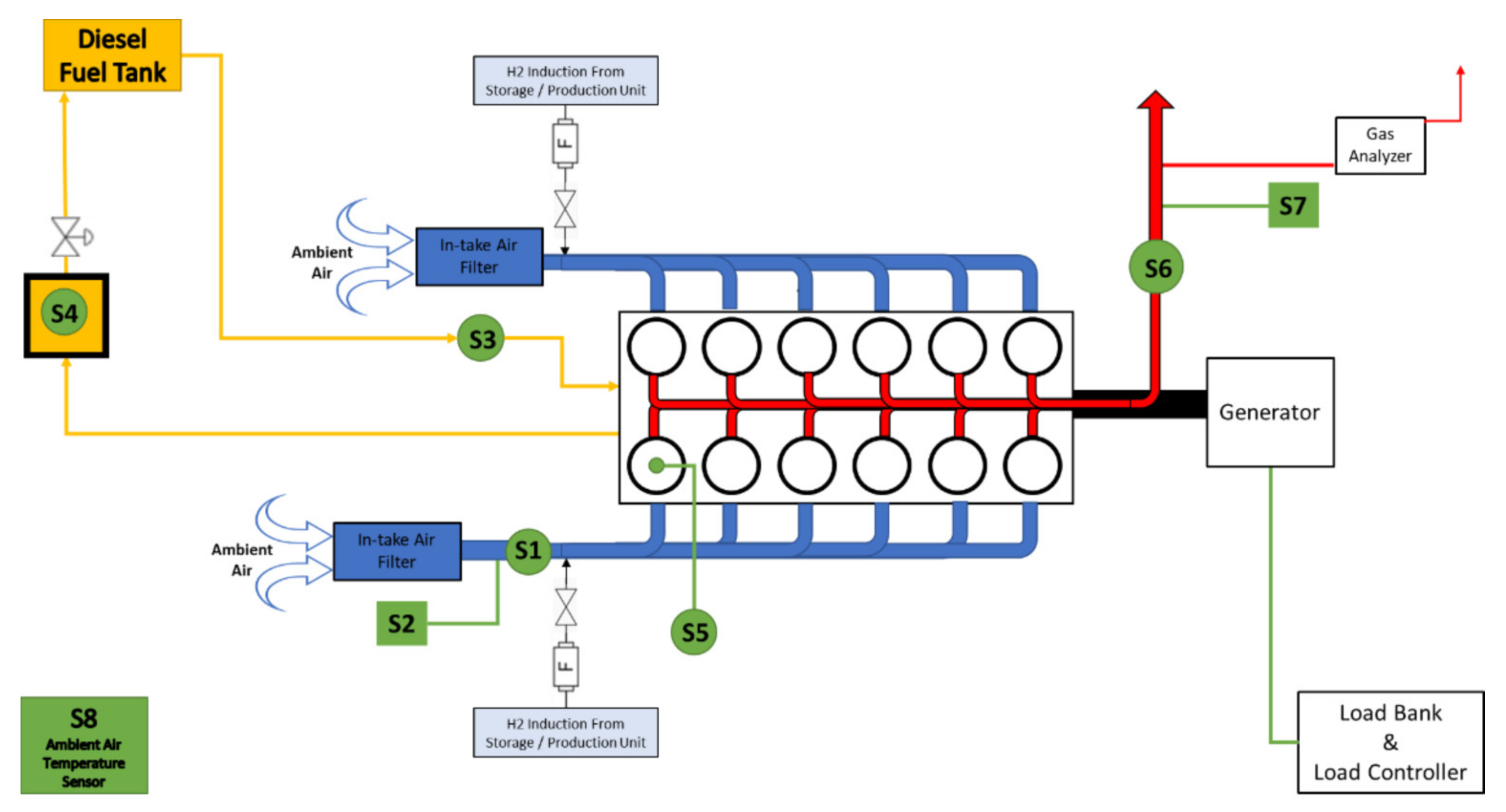
The general arrangement of the experimental configuration is shown in
Figure 1 and includes the required modifications that were performed to install the sensors and measurement units.
The hydrogen is inducted into the two manifolds after the measuring location of the intake air volumetric flow rate (S1 in
Figure 1) and temperature (S2 in
Figure 1). Each H
2 induction point is equipped with a hand valve, as shown in
Figure 1, to isolate H
2 supply, in cases of pure diesel experiments. In addition, and sequential to each isolation hand valve, a flashback arrestor was installed (“F” in
Figure 1 and
Figure 2b) to protect the H
2 unit and measurement equipment in case of a backfire (flashback) occurrence in the intake pipe. The configuration of the H
2 supply unit is schematically shown in
Figure 2a.
As the first step of the HYMAR project, the size and power of the H
2 production unit (electrolyzer) to feed the selected engine has to be calculated. In order to complete this, pure H
2 was supplied from a pressurized bottle to define the required quantity of H
2 that achieves substantial diesel fuel reduction and improved emission characteristics. The H
2 supply unit consisted of a cylinder/bottle that contained pure H
2 that was pressurized at 200 bars. The bottle was equipped with a double-stage pressure regulator which was used to adjust the H
2 flow rate. H
2 flow rate was monitored by the OMEGA FMA-1600A Series Mass flow meter (Omega Engineering, Manchester, UK) for Gases. The H
2 flow meter displayed the instantaneous volumetric flow rate (S9 in
Figure 1), along with the temperature (S10 in
Figure 1) and pressure (S11 in
Figure 1) at the measuring location, thus allowing the accurate calculation of the H
2 mass flow rate.
The inlets of the air intake manifolds were extended and modified accordingly to allow the installation of the H
2 induction ports/valves and the intake air flow meter. Moreover, additional filters were installed at the end of each intake pipe, to allow proper operation under dusty conditions, as shown in
Figure 3.
The intake air volumetric flow rate (S1 in
Figure 1) and temperature (S2 in
Figure 1) were measured at one manifold only, assuming identical conditions between the two manifolds. For the installation of the air flow meter, a straight pipe section was constructed and installed, following the instructions of the instrument’s manufacturer. Installing the air flow meter on a long straight section, the symmetry of the flow profile around the axis of the pipe was enhanced, since the effects of geometrical changes of the intake duct (e.g., bending, cross sectional area and/or geometry changes, connections, etc.) were minimized. Regarding the measurements of the intake air flow rate, a Sigma 401 Thermal mass flow sensor was used. It is noted that of the intake flow rate had an unsteady behavior due to the multiple opening and closing events of the intake valves. Therefore, in order to measure the intake air flow rate as accurately as possible, the average value of the signal was calculated for a period of at least 5 min, which accounted for a large number of opening and closing events of the intake valve, which was equal to 3750 at the engine speed of 1500 RPM (1500 × 0.5 × 5). Apart from the intake air temperature that was measured by the flow meter inside the pipe prior to the manifold, the ambient air temperature was also recorded using a SIKA T45 thermocouple which was fixed at one corner of the room (S8 in
Figure 1), since ambient conditions might affect an engine’s operation and thus measuring quantities.
The in-cylinder pressure was measured only at one cylinder (S5 in
Figure 1), for which the factory-installed heater plug was removed to fix an in-house constructed adaptor on which the Kistler 6613CP pressure transducer was mounted. Kistler pressure transducer was connected on the PYTHIA-VI data acquisition device and Diagnostic System.
Regarding the emission characteristics of the engine under pure diesel and dual H
2-diesel operation, the Sigma 8000 Series Gas Analyzer was used to record O
2, CO, CO
2, Nitrogen Monoxide (NO), Nitrogen Dioxide (NO
2), and UHC, with a sampling rate of 5 s (i.e., all gases were measured every 5 s). The volumetric concentration of O
2 and CO
2 was measured, while all other elements were measured as parts per million (ppm). At the same location where the Gas Analyzer was installed, a K-type thermocouple was installed (S7 in
Figure 1) to record the exhaust gas temperature (EGT). In addition, the G16 Smoke Density Monitor of Green Instruments was installed to record the smoke concentration (S6 in
Figure 1) in the exhaust gases. The Smoke density monitor consisted of a transceiver and a reflector, installed at 90 degrees with respect to the exhaust flow direction. The intensity of the generated laser beam was compared against the intensity of the reflected one, calculating the opacity which was considered to be inversely proportional to the smoke concentration. It is noted that the proper installation of the smoke detector required the supply of purge air with proper flow rate at the transceiver and the reflector to protect them from overheating and to avoid the deposition of particulate matter on them.
The diesel fuel supply system of the engine was designed in such a way to have an inflow diesel flow rate that was almost proportional to the rotational speed of the engine, while at the same time a significant quantity of fuel returns to the diesel main tank, according to the consumption. In other studies, the diesel fuel consumption was measured either by using a scale or a fuel balance system that recorded the weight of the fuel tank, or by using a burette to monitor and measure the fuel volume change of the main tank. In the present study, none of these methods were easily applicable. Therefore, the inflow fuel flow rate and fuel return from the engine were recorded separately, and the fuel consumption was calculated by subtracting the fuel flow return from the inflow flow rate. Inflow fuel flow rate was recorded by a Coriolis-type mass flow meter, the DN3 Micro-bend version of LZYN-Coriolis mass flowmeter, that achieves 0.1% accuracy for flow range of 10–120 kg/h. The inflow flow rate of the engine at 1500 RPM ranged between 35 and 45 kg/h, and its average value was calculated to define a single value in each test. The diesel fuel return was directed to a small tank (S4 in
Figure 1) before being directed to the main tank. The small tank was completely open on its upper face. During a measurement session, the fuel flow to the main tank was restricted by closing a hand valve (after S4 in
Figure 1). Thus, the level in the small fuel tank increased with a rate that was proportional to the fuel flow return, since the cross-sectional area of the tank (25cm × 25cm) was constant along its height. The fuel level change in the small tank was recorded by an ultrasonic sensor which recorded the distance from the upper face of the small tank. The ultrasonic flow sensor had an accuracy δFuelLevel of 1mm which corresponded to 0.0625 L (i.e., 0.25 × 0.25 × 0.001 m
3). The mass flow return was calculated by multiplying the calculated fuel volume return with the density of the fuel, which was 843.7 kg/m
3. After the end of a measuring session, the hand valve opened to allow the accumulated diesel fuel to return in the main fuel tank. The fuel return measurement is given by:
Thus, the accuracy of the fuel return measurement is given from:
resulting in an accuracy of 0.0884 L. In order to achieve the same level of accuracy with the Coriolis flow meter, that measures the inflow flow rate, the fuel level in the return tank changed by 1.414 m. For the experiments performed for the HYMAR project though, the change was about 10 cm for each measurement, corresponding to an error of about 1.5%, since larger changes would require much longer experiments. Thus, the accuracy of the fuel consumption was defined by the fuel return accuracy which was one order of magnitude larger than the accuracy of the inflow fuel flow. The accuracy of the fuel return measurement can be enhanced by decreasing the cross-sectional area of the return tank to achieve faster level increase at the same duration. However, this would require an ultrasonic sensor with smaller beam angle. For a better accuracy, the fuel return tank should be replaced with a Coriolis-type mass flow meter, similar to the one installed for the inflow fuel flow rate.
The signals of S1, S3, S6, S7, and S8 were recorded by the Tektronix Keithley DAQ6510 Data Acquisition and Logging Multimeter System, equipped with the 7700-model module. The DAQ6510 with the 7700 module has a total bandwidth capability of 50 Mhz and was able to measure thermocouples’ signals, voltage signals, and current signals. Data acquisition was controlled by the Kickstart data logging application. The recording of S5 was controlled by the PYTHIA-VI system. S4 was connected to an Arduino UNO and the recording of S4 was controlled by a PC terminal. The signals of S2, S9, S10, and S11 were not recorded, but they were monitored throughout the experiments. The measurements of the emission characteristics were recorded and stored on the Gas Analyzer. At the end of all experiments, data were collected from the different devices to be analyzed.
The generator was connected to a monitoring panel, where the frequency output and the power output (kW and kVA) were displayed, allowing for more accurate monitoring of engine speed and load, compared to the embedded analog tachometer of the engine and the analog load controller. It was also connected to a 300 kW Grestchic Load Bank with a step resolution of 1 kW at 400 V 3-phase current. A controller was connected to the load bank to select the load for each set of measurements. The load and the rotational speed of the engine were kept constant during a set of measurements, having only minor temporal fluctuations as observed from the electricity output monitoring panel.
Even though the rated power of the engine was 112 kWe, its operation was limited below 40 kWe, which was less than 50% of the rated power, to account for potential operational aging degradation. All experiments were performed at a constant rotational speed of 1500 rpm. The in-cylinder pressure sensor sampling rate was 10,800 Hz (i.e., dt = 9.26 × 10⁻⁵ s), which corresponded to a sample every 0.8 Crank Angle Degree (CAD) when the engine speed was set to 1500 RPM.
Before initiating the gathering of measurements, the engine was operated for more than 30 min to ensure that a steady state operation was reached. This was decided by monitoring the EGT. After a plateau was reached in the graph of EGT versus time, it was assumed that the temperature of the engine’s cylinders was also in a quasi-steady state condition; thus, a steady state was reached. The fact that an air-cooled, rather than a water-cooled engine was used resulted in longer times for an almost constant EGT to be reached. Because of the long times that were needed to reach an almost constant EGT when the engine load was changing, it was decided to keep the load constant and then vary the H2 induction flowrate. After finishing a complete set of measurements for a specific load, the load was adjusted to the new value and as soon as the EGT reached a new plateau value, the new set of measurements for different H2 induction flow rates were gathered.
5. Conclusions
The new regulations regarding significant emission reduction, that have to be achieved in the years to come, pose significant challenges to the industrial and the automotive sectors, because of their wide dependence on Internal Combustion (IC) engines, and especially Compression Ignition (CI) diesel engines. Even though the technology of CI diesel engines has improved lately, emission reduction levels are not adequate. Using alternative fuels, either to completely replace or supplement diesel fuel in CI engines is an attractive solution that can maintain the use of CI diesel engines in the mid-term and long-term energy transition, without significant changes/modifications on the existing technology. Compared to other alternative fuels, hydrogen (H2) offers the important benefits of zero carbon content, abundant quantities, and production capability using renewable energy sources (e.g., through electrolysis).
The use of H2 as a supplemented fuel in CI diesel engines needs further investigation and research, since adverse effects might occur according to the operation load, H2 induction method, and other engine characteristics. The present study collects and presents in tabulated form the main engine characteristics and operational parameters that were used by several experimental studies to assist the comparison of the results presented in each study. Such comparison and categorization might help in the understanding of contradictory results reported in the literature, that might be attributed to deviations in engine characteristics and engine technology level. Moreover, the tabulated presentation of the literature may be used by other researchers trying to design their own experiment or trying to compare their results with results reported in studies with similar engine characteristics and operational parameters.
Apart from the literature review and categorization that was performed in the first part of this paper, the experimental design/configuration that was developed to study the effect of H2 supplementation on a heavy-duty generator-set (Genset) four-stroke CI diesel engine was presented in detail. The required modifications performed on the engine’s accessories and the installation of the instruments that monitor the engine operation were presented.
Future studies may present, analyze, and discuss the measurements gathered during the experiments on such a heavy-duty engine. In the future, the tabulated presentation of the literature can also be expanded by including more experimental studies on dual H2-diesel fuel four-stroke CI engines. In addition, the tabulated presentation may be expanded to include the main conclusions of each study, allowing for further analysis and discussion that might lead to useful conclusions on identified patterns according to engines’ characteristics and performance parameters.


