1. Introduction
Marine internal combustion engines have a high (almost 98%) market penetration in the global merchant fleet due to their high maturity and efficiencies [
1,
2]. Marine internal combustion engines are a mature technological solution with vast knowledge and expertise. However, the challenge for ICE technology is to mature by combusting alternative fuels to abide by the strict decarbonization targets of the IMO, due to the industry’s ~3% greenhouse gas (GHG) contribution to global pollution. Amongst the many alternative green fuels, hydrogen has increased in popularity as a very promising energy carrier [
3]. It is noteworthy that the initial interest is for retrofitting ICEs to combust hydrogen focused on spark ignition engines via port-fuel injection [
4,
5]. The literature for ICEs burning hydrogen is exhaustive containing a heritage of more than one century [
5,
6]. However, for shipping, dual fuel diesel engines, either two-stroke or four-stroke, are the most popular [
1,
2]. This is because dual-fuel mode engines can respond with relative ease to a vessel’s operating conditions, they are independent of cargo type and size, and they can easily switch and operate on various fuel modes such as liquid fuels or blend of gas-liquid fuels [
1,
2]. The marine industry is currently testing hydrogen as a drop-in fuel for ICEs [
7]; for instance, Wärtsilä is currently testing hydrogen for its marine ICEs [
8,
9].
In the marine context, hydrogen can only be used in dual fuel mode in compression engines [
10]. Although large emphasis has been placed on the decarbonization of shipping via green hydrogen, the development of “advanced hydrogen ICEs”, either as direct injection or dual-fuel injection, is still at a conceptual phase [
4].
In terms of physical properties, hydrogen is an excellent energy carrier with a high Lower Heating Value, almost triple compared to diesel. However, hydrogen is a light gas, whereby under atmospheric conditions its volumetric energy density is significantly lower compared to diesel (almost 3000 times lower [
10]). Therefore, suitable storage means are required to deal with this low volumetric energy. Storage solutions include compression, liquefication and even storage by chemical means or metal hybrids (via physical adsorption) [
11,
12]. On-board a vessel, hydrogen storage presents different challenges compared to its stationary or automotive counterparts [
1,
10,
13], which may also imply a sacrifice of cargo space to accommodate equipment necessary for hydrogen. The wide flammability range of hydrogen enables the fuel to achieve low NOx emissions as well as increased brake thermal efficiency [
14].
The vast number of recent publications relative to the application of hydrogen in diesel engines clearly supports the inherent capacity of diesel engines to utilize their superior combustion characteristics compared to spark ignition engines without radical modifications of the existing engine infrastructure. Contemporary literature relative to the application of hydrogen in existing diesel engines demonstrates a long and successful endeavor of various researchers towards their effort to exploit the benefits of air—hydrogen combustion in a conventional diesel combustion environment with the possibility for reducing the emission footprint and the potential for improving energy efficiency and fuel saving. The interested reader is referred to studies [
15,
16], where recent and prior publications on hydrogen addition in diesel engines are discussed.
The present work, in the best case, attempts to provide a thorough review of the pollution characteristics of dual fuel hydrogen/diesel combustion in existing diesel engines that will enable the use of hydrogen as a viable solution to the operational and environmental challenges of a typical diesel engine. The objective of this work and the HYMAR project is to determine the required quantities of hydrogen that achieve a substantial reduction in pollutant emissions for a heavy-duty marine auxiliary gen-set engine. Afterwards, the size and the required power of a hydrogen production unit (electrolyzer) will be calculated, allowing for the proper industrial design for onboard installation. The experimental methodology and research findings of the HYMAR project, which utilizes the combustion of hydrogen in a marine genset, are presented and discussed. Therefore, the scope of this paper is to illustrate the latest research activities and achievements related to the pollution performance characteristics of hydrogen in marine internal combustion engines. In
Section 2, the relevant literature is surveyed and discussed.
Section 3 presents the HYMAR setup, the experimental configuration of a heavy-duty auxiliary generator-set (Genset) engines, the necessary retrofits and the experimental campaigns.
Section 4 presents the results and discusses them with reference to the available literature. Finally, in
Section 5 conclusions are presented with an overall summary and future recommendations for RTDI in terms of hydrogen combustion in marine ICEs.
2. Background on Effect Hydrogen Combustion in Dual-Fuel Engines Has on Pollutant Emissions
Historically, hydrogen participation in dual-fuel diesel engines with low to moderate EGR levels (less than 25%) was utilized to offer performance-emission (such as break thermal efficiency and brake specific fuel consumption) as well as emission-emission (CO, CO
2, NOx, UHCs and PMs) trade-offs as opposed to without hydrogen [
17,
18,
19,
20,
21,
22]. Most studies report that the addition of hydrogen can reduce CO, CO
2, and smoke emissions but can increase NOx emissions [
23], hence the addition of EGR to reduce the latter. However, the challenge is to achieve successful engine tests at higher EGR levels (above 30%). High EGR levels are needed because of the stringent NOx reduction requirements but with adverse effects on combustion stability and engine performance. However, with the addition of hydrogen as a dual fuel, these issues can be mitigated [
24]. For example, Shin et al. [
25] in their study observed a smoother engine operation, reduced peak cylinder pressures and peak heat release rates with the addition of hydrogen even up to 31% EGR levels. They also mentioned a 25% decrease in NOx emissions “as the duration of the main combustion sequence increased with EGR application” [
5]. On the other hand, the use of EGR in compression ignition engines under dual fuel mode can increase particulate emissions [
14]. Miyamoto et al. [
26] investigated the effect of adding hydrogen to the induction manifold on the combustion and exhaust emissions characteristics of a diesel engine with EGR rates as high as 70% in 10% increments with and without hydrogen enrichment. They determined that NO emissions under H
2 enrichment were higher than the corresponding diesel function only for EGR rates of up to 40%, due to accelerated heat release characteristics due to hydrogen enrichment and its consequent participation in the combustion sequence. However, for EGR rates higher than 50%, the addition of hydrogen had no effect on the NO emission profile.
Zhou et al. [
27] examined a “diesel-hydrogen co-operated combustion strategy” where hydrogen was naturally aspirated in the engine whereby 10%, 20% and 30% of the total energy was substituted at various selected modes. They concluded that the addition of hydrogen aided in the inhibition of soot formation (based on the HACA mechanism—H
2 abstraction and C
2H
2 addition), because the H/C ratio decreases [
27]. Moreover, they reported an increase in NOx of around 17%. Therefore, there is an implied trade-off between PM and NOx emissions, as mentioned by Deb et al. [
28]. Roy et al. [
29] performed experiments using hydrogen in a super-charged diesel engine and reported up to 90% of the total fuel energy could be provided by hydrogen. This was achieved with a highly diluted intake charge using nitrogen (which was added to avoid knocking with up to 13% higher IMEP), but the investigation was conducted at limited engine operating conditions. However, the results regarding emissions were very promising as they reported 5 ppm in CO, 15 ppm in HC but with rather high NOx emissions (of the order of 100–200 ppm or more). Other studies observed engine speed and load as being limited by the hydrogen substitution ratio in order to avoid knocking [
25,
27,
29,
30,
31,
32,
33]. Liew et al. [
34] examined hydrogen combustion in a heavy-duty turbocharged diesel engine with EGR and reported that a hydrogen addition of 2% to 4% (vol.% in intake mixture) “increased substantially” NO
2 emissions but reduced NO emissions. Thus, minimally affecting NOx emissions, while “substantially” reducing PM, HC, and CO
2 emissions.
Note that most of the literature, and the aforementioned studies, mainly focus on regulated emissions. However, emphasis must also be placed on unregulated emissions such as aldehydes, alkenes and arenes due to their carcinogenic impact and consequent health implications [
27]. Zhou et al. [
35] examined unregulated emissions in a diesel engine with hydrogen addition and found that “is effective in reducing” the aforementioned unregulated emissions because of hydrogen’s ability to improve the ICE combustion performance.
In addition to improving combustion characteristics at high EGR levels, it is noteworthy that the recent literature on hydrogen developments with ICEs focus on the potential benefits of hydrogen blending with biofuels, such as biodiesel. Due to hydrogen’s physical-chemical properties, it can improve engine performance characteristics and combustion characteristics of the blended fuel. Hydrogen can also improve emissions characteristics in terms of CO, UHC and smoke formation but with increased NOx emissions [
36]. Khatri et al. [
37] found that HC, CO and NOx emissions are reduced by 5.7%, 88% and 83%, respectively, after blending hydrogen and biogas with diesel in a single cylinder, four-stroke CI engine. Estrada et al. [
38] reported markedly reduced CO and CO
2 emissions with hydrogen for the same power output when blended with neat diesel. On the contrary, they report higher NOx emissions for the same power output.
The exhaust emissions, and especially NOx concentration, can also be mitigated by installing an after-treatment device, such as a Selective Catalytic Reactor (SCR). According to the application and the characteristics of the engine, a high-pressure or low-pressure SCR technology shall be selected. For high-speed diesel engines, a low-pressure SCR device is used because of its minimum impact on the turbocharger’s performance. However, at low loads, where the exhaust gases exhibit a lower temperature, SCR may not work properly since the reaction principle requires exhaust gas temperatures higher than 280 °C [
39]. For this reason, at low-speed engines, where the exhaust gases have lower temperature, a high-pressure SCR is more appropriate to effectively reduce NOx emissions. More details on the SCR technology, its development, and its application on marine diesel engines can be found in the detailed work of Zhu, Y. et al. [
39]. Summarizing the above, SCR technology cannot be used without cost on its performance or the engine’s performance, especially at low load working conditions. However, achieving higher exhaust gas temperatures at low load conditions, SCR technology will be effective at lower loads, widening its operation and mitigating its impact on the engine’s performance. Along these lines, the addition of hydrogen in ICEs at certain concentrations may result in increasing exhaust gas temperature. Therefore, the understanding of the effects of hydrogen addition in diesel engines is very important to either improve the performance and emission characteristics of diesel engines or improve the effectiveness of after-treatment technologies, such as SCR and EGR, that are the most practical and popular solutions for reducing NOx emissions from marine diesel engines.
It is obvious that there are contradicting and conflicting statements in the literature of pollutant formation from hydrogen combustion in dual-fuel diesel engines [
16], especially on the effects on NOx and EGR. This is primarily due to the different experimental conditions (such as EGR levels, supercharging, turbocharging, injection strategies), fuel compositions with regards to hydrogen energy share and engine setups. Hence, our current work is to present the experimental methodology and main findings of our experimental campaign with reference to the available literature. It is a known fact that the shipping industry is generating a large amount of pollutant emissions as well as GHG. If stakeholders of the shipping industry are willing to achieve the decarbonization goals set by the International Maritime Organisation and the European Green Deal, marine industry obliged to perform retrofits of existing and potentially very old engines. Therefore, experimental investigations are performed on an old (1966) naturally aspirated engine without EGR to investigate the impact of emissions due to the addition of hydrogen to the fuel blend.
3. Experimental Methodology
The following section presents HYMAR’s experimental apparatus and instrumentation. All tests have been performed on a heavy-duty marine auxiliary generator-set (Genset). The latter diesel engine comprised of a four-stroke, naturally aspirated, air-cooled, 12-cylinder, 19L “Deutz A12L 714” (Germany), manufactured in 1966. The engine is fueled by non-Sulphur containing pure diesel, suitable forhigh-speed diesel engines. Engine specifications as reported by the manufacturer are presented in
Table 1. The specific auxiliary generator has no EGR system. The 12 cylinders of the engine are placed in two banks at a 90° angle on the crankcase in a vee arrangement As seen in
Table 1, the rated power output under full load is 112 kWe at 1800 rpm with a Compression Ratio (CR) of 19.2.
The fuel consumption of the engine varies from 140–166g/kWh depending on the revolutions per minute and the load of the engine. At STP conditions (P = 1 bar, T = 298 K) the aforementioned consumption corresponds to 41.84 MJ/kg.
The valves of the engine open at 18.5° before TDC (Top Dead Center) and close at 50.5° after the BDC (Bottom Dead Center). The valves that remove the combustion products from the cylinders open at 62.5° before BDC and 18.5° after TDC. At 1500rpm, the injection of the fuel in the cylinder initiates at 24o before TDC, while the injection nozzle opens at a pressure of 126.66 bar.
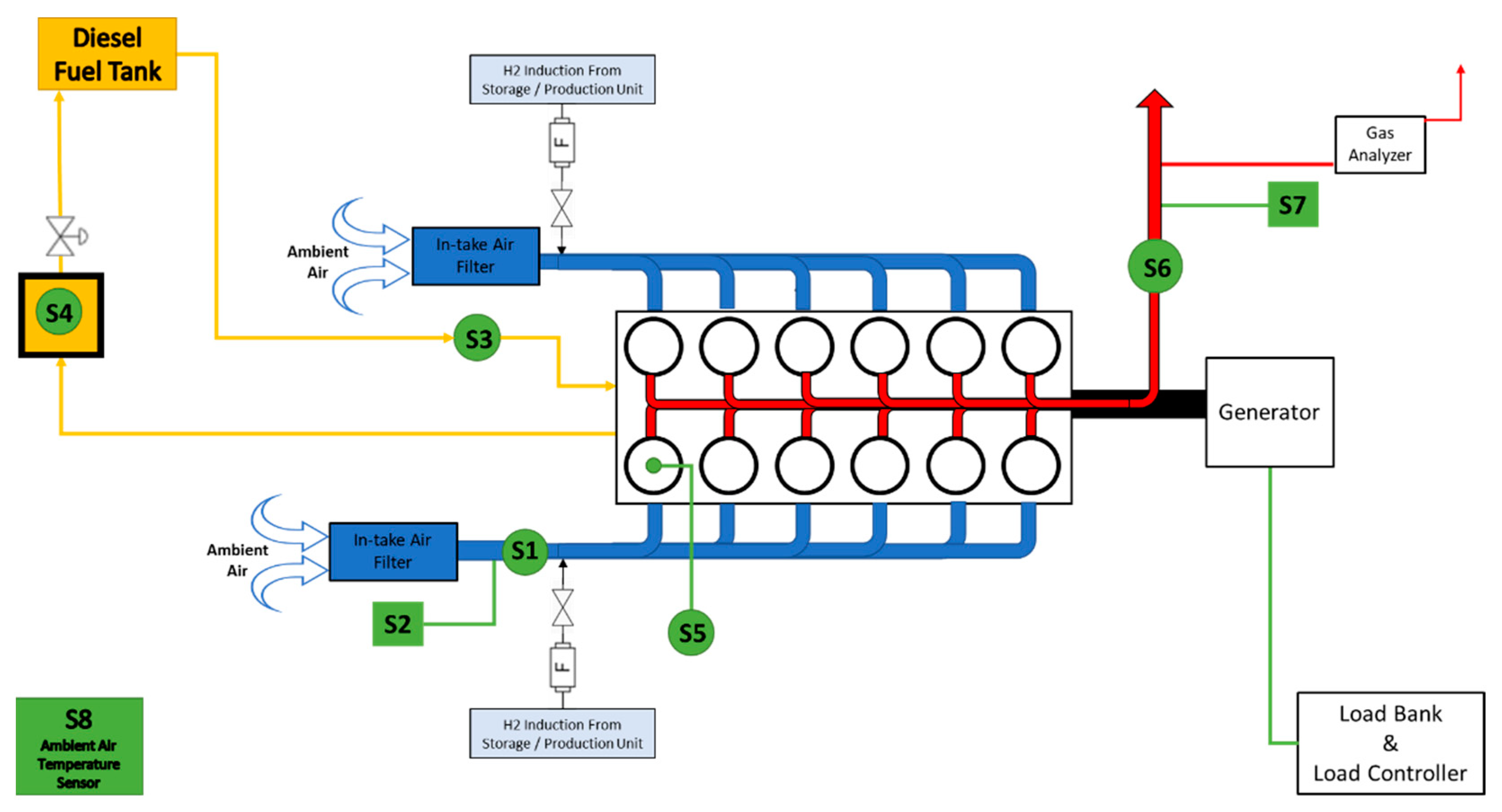
Figure 1 depicts a schematic representation of the experimental setup used, including engine modifications performed in order to achieve hydrogen addition in the air inlet of the ICE, as well as measuring instruments used to collect all the necessary data.
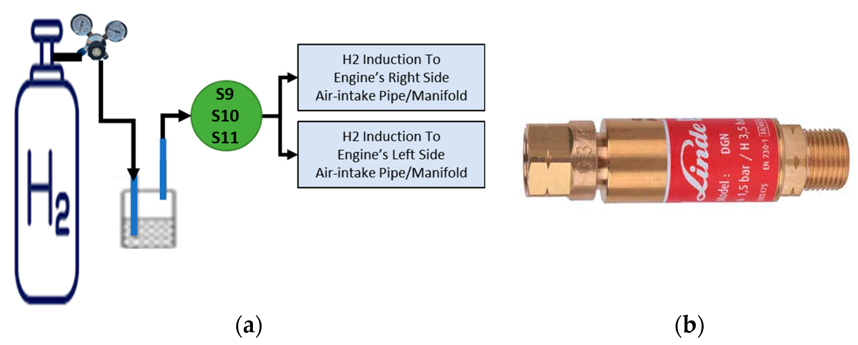
Figure 2a presents the configuration of the hydrogen supply to the air inlet of the engine. Hydrogen used for the purposes of the experimental setup was provided by Linde plc and had a purity of 99.999%. Hydrogen was contained in a cylinder at 200 bar pressure and the latter was equipped with a flashback arrestor (
Figure 1 and
Figure 2b, “F”) in order to ensure that in case of backfire, the cylinder is intact. The point where hydrogen is added to the air inlet of the engine is located after the air filters and the two sensors measuring the airflow intake and air temperature. Thus, these two parameters are not affected by the hydrogen flow, which was measured with the use of an OMEGA FMA-1600A Series mass flow meter (Omega Engineering, Manchester, UK) for gases. The latter, not only measures the instantaneous flow rate of hydrogen, but also measures the temperature and pressure output of the gas. As a result, the hydrogen flow rate was calculated with the highest possible accuracy. The flow rate of hydrogen from the cylinder was controlled with the use of a two-stage pressure regulator, attached to the top of the H
2 cylinder. The air flow intake measuring device and air intake temperature sensor (Sigma 401 Thermal mass flow sensor) were installed only on one manifold assuming identical air flow and temperature conditions in the engine. In order to reach best possible accuracy on measuring the air flow intake of the engine, the air flow measuring device was placed on the top of a long, straight section, thus avoiding bends and achieving optimal air flow conditions. The ambient temperature was measured with the use of a SIKA T45 thermocouple placed in the engine room (
Figure 1, S8).
The air inlets (
Figure 3a) of the engine were equipped with dust filters (
Figure 3b) and at the hydrogen induction points on/off valves were installed that allowed tests to be performed with and without hydrogen.
In order to measure the pressure of the cylinder under operating conditions, a pressure sensor (Kistler 6613CP) was installed in one cylinder (
Figure 1, S8). The latter pressure transducer was connected to the PYTHIA-VI data acquisition device and Diagnostic System. At a constant rotational speed of 1500 rpm, where all tests were performed, the in-cylinder pressure sensor sampling rate was 10,800 Hz (i.e., dt = 9.26 × 10
−5 s), which corresponds to a sample every 0.8 Crank Angle Degree (CAD).
Exhaust gaseous emissions of the diesel ICE were continuously monitored for both experimental conditions (diesel only and diesel plus hydrogen) with the use of a Sigma 8000 Series Gas Analyzer, capable of measuring the concentration of CO (carbon monoxide, ppm), CO
2 (carbon dioxide, %vol.), NO (nitrogen oxide, ppm), NO
2 (nitrogen dioxide, ppm), O
2 (oxygen, %vol.) and UHC (unburned hydrocarbons, ppm), at a sampling rate of 5s. The exhaust gas temperature (EGT) was also monitored with the use of a K-type thermocouple (
Figure 1, S7) which was placed next to the probe of the gas analyzer at the exhaust gas pipe of the engine. The gas analyzer records and stores the data from the concentration profiles of the aforementioned gaseous pollutants.
Prior to the gas analyzer, a Smoke Density Monitor device (G16, Green Instruments) was installed (
Figure 1, S6) in order to calculate the opacity of the exhaust gas stream. The latter consists of mainly two parts, a transceiver and a reflector, placed vertically (90°) to the exhaust pipe. The operation principle of the smoke density monitor lies on the intensity of a laser beam transmitted on the exhaust gas flow and reflected back to the receiver. The smoke concentration of the exhaust gas stream is inversely proportional to the opacity calculated by the comparison of the intensity of the transmitting and reflecting laser beams. The smoke intensity monitor is sensitive to the exhaust gas temperature and as a result, to avoid overheating of the instrument, atmospheric air is purged at a specific flow rate through the transceiver and reflector. Moreover, purged air prevents particulate matter deposition on the mirror of the reflector, thus ensuring the accuracy of the measurement.
It must be noted that the fuel supply system of the engine was specifically designed so that the rotational speed of the engine is almost proportional to the fuel inflow rate. Even so, significant quantity of fuel returns to the fuel tank without being combusted. The amount of fuel return can be measured either with the use of a scale or by using a burette to measure the volume change in the fuel tank. However, these two types of measurements lack accuracy and were not applicable in the present study. As a result, the two fuel flows (intake and return) were recorded separately and the fuel consumption was calculated by subtracting the fuel flow return from the fuel inflow. For measuring the fuel intake of the engine, a Coriolis type (DN3 Micro-bend version of LZYN) mass flow meter (
Figure 1, S3) was used. The latter is capable of measuring duel flow rates between 10–120 kg/h at a 0.1% accuracy. For the purposes of the present experimental study, and at a constant 1500 rpm operation of the engine, the fuel consumption was found to be between 35–45 kg/h.
A small custom-made tank of known volume (
Figure 1, S4) was introduced prior the main fuel tank in order to calculate the volume of the fuel return, which was then redirected to the main fuel tank. The cross-section area of the return fuel tank was 625 cm
2. Thus, during the operation of the engine, and for a specific period, by closing the outlet of the return fuel tank (
Figure 1, after S4), the volume of fuel in this tank increased and was measured with the use of an ultrasonic sensor connected to an Arduino UNO microcontroller. As a result, the volume of the fuel return can be easily and accurately calculated automatically, simply by multiplying the constant cross-sectional area with the level of the fuel in the fuel return tank. The mass of the fuel return is then calculated by multiplying the fuel volume return with the density of the fuel (843.7 kg/m
3). When the fuel return is measured, the hand valve at the bottom of the return fuel tank is opened and the fuel flows back to the main tank [
37].
The accuracy of each sensor/measuring device is shown in
Table 2.
A Data Acquisition and Multimeter System (Tektronix Keithley DAQ6510, 7700 model, 50MHz) was connected to the S1, S3 and S6–S8 (
Figure 1) and collected all data recorded in the form of voltage or current signals and transformed the signals into measurements. Data from S2 and S9–S10 were collected separately and after the completion of each experimental session, all data from all the measuring instruments used were collected for further analysis.
In order to increase the load of the engine resulting in an increase of the fuel consumption, the engine was connected to a 300kW Load Bank (Crestchic Loadbanks, 3-phase, 400 V, 50 Hz). The load could be altered with the use of a controller which was connected to the load bank. For the set of experiments presented in this article, both the load as well as the rotational speed of the engine were kept constant at 20 Kw and 1500 rpm respectively. The exact frequency (Hz) and power output (kW) of the IC engine were displayed on a monitoring panel in order to monitor accurately the load and speed of the engine.
Although the maximum rated power of the ICE used was 112 kWe, all tests were performed at 24.25 kWe (20% of the rated power) since the condition of the engine in combination with the age of the engine might result in an engine failure. Moreover, at low engine loads and fuel consumption, the effect of hydrogen addition in the feed stream is expected to be significant.
It is important to mention that prior to each experimental session, the engine was operated for more than 30 min so that steady state operation was achieved. This was confirmed with the use of the EGT graph versus time, when no significant change of the exhaust gas temperature was observed. Generally, EGT steady state is achieved faster in water-cooled engines, rather than the air-cooled engine used in the present experimental setup and, therefore, the engine load was kept constant while the hydrogen concentration added to the inlet varied.
4. Preliminary Results and Discussion
The sets of experiments presented in this paper were based on a constant net electric power output of 24.25 kW, where various hydrogen volumetric flow rates were examined. The experiments were performed at a sea-level location during a hot summer day with an ambient temperature ranging between 39–43 °C. To ensure that measurements were performed under steady-state conditions of the engine, the engine was operated for more than 30 min, allowing the graph of EGT versus time to reach a plateau. Afterwards, the hydrogen induction flowrate was varying, allowing the EGT to reach a new plateau value, if any, before starting to gather measurements. For each hydrogen flowrate tested, recordings of 5 min at steady-state conditions were conducted and the mean value of each signal was calculated and presented in this study.
The present study includes preliminary results that are shown in
Table 3. The values of H
2 flow rate are given in liters per minute (LPM) at standard conditions (25 °C, 1 bar).
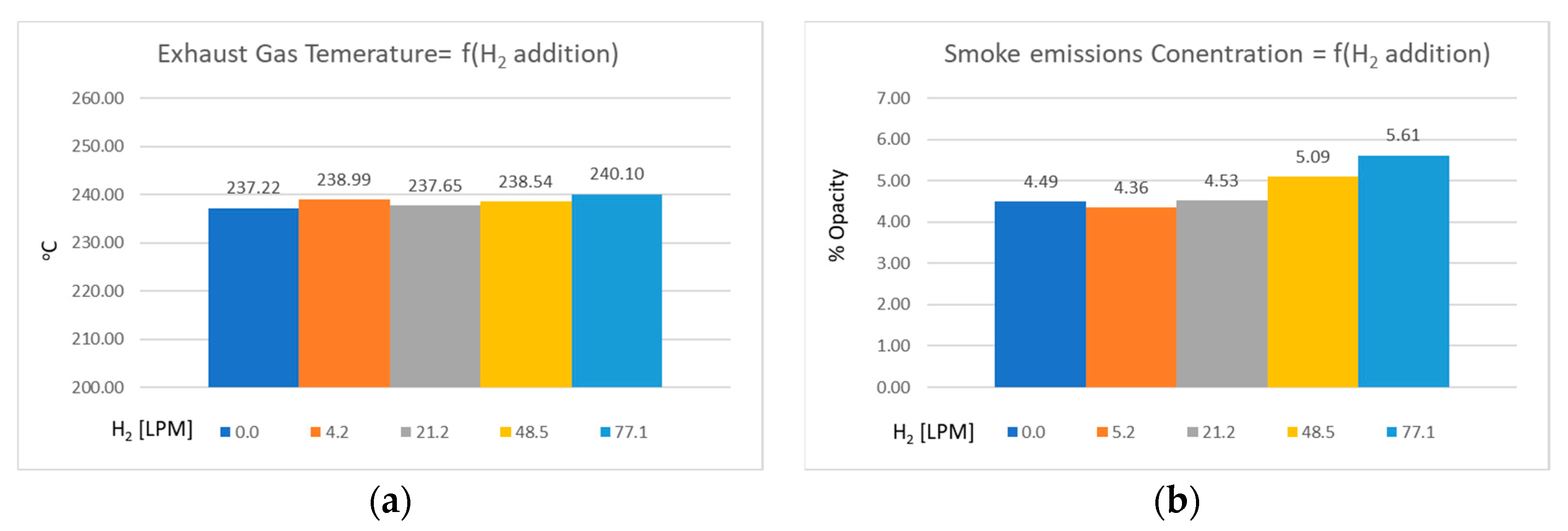
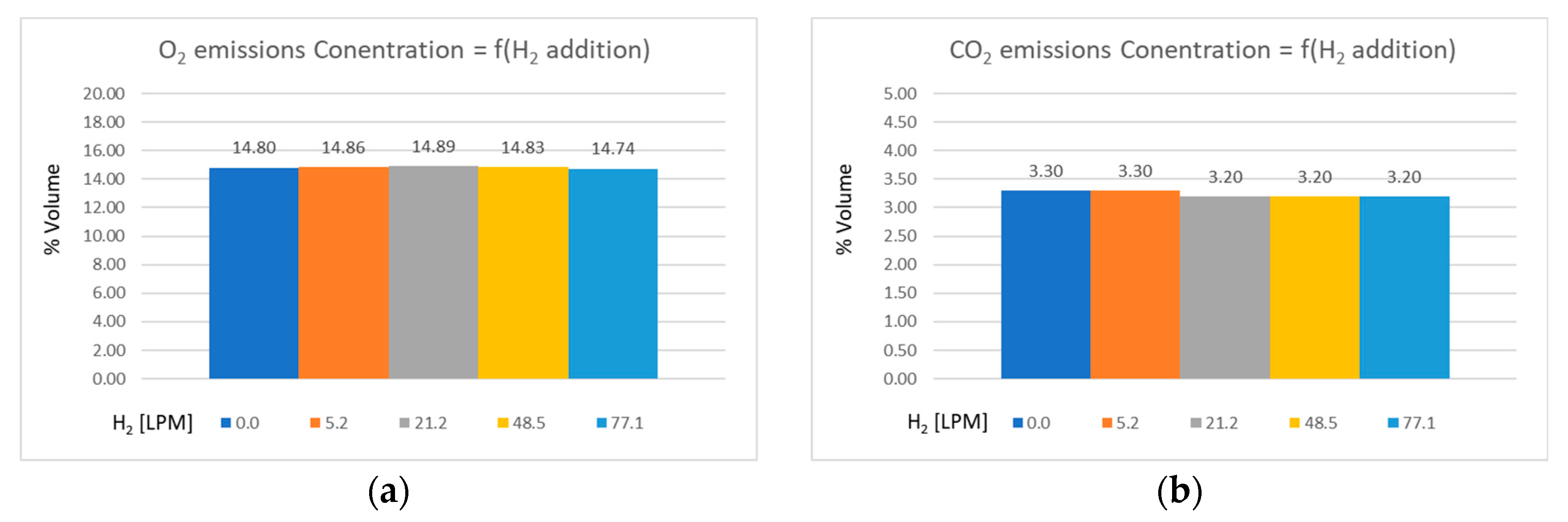
The engine operated at low loads. No significant change was observed in EGT and smoke. An increased amount of hydrogen is required to significantly affect H/C ratio and, thus, decrease soot formation. Oxygen is considered to remain constant in the exhaust stream since no consistent trend occurred by increasing hydrogen flow, while differences are within the precision accuracy of the gas analyser (±0.1%), which corresponds to a change in around 1% of the reference value. An increased amount of hydrogen led to the reduction in UHC and a slight decrease in CO
2 emissions occurred for hydrogen flowrates above 20 LPM. A significant decrease in NO concentration was also observed (in accordance with relevant findings in the literature), although the total NOx concentration is expected to be increased. No knock phenomena and no significant deviation in the in-cylinder pressure diagrams occurred. The results presented in
Table 3 are also demonstrated in a bar-chart format in
Figure 4,
Figure 5 and
Figure 6.
Summarizing the above, the increase in hydrogen flowrate into the intake air, up to a volumetric percentage of 1.7%, affects only the concentration of NO and UHC in the exhaust gases by a maximum reduction of 10 and 80 ppm, respectively, which corresponds to approximately 18% and 30% reduction compared to the Diesel only operation, respectively.
NO, which is the major component of NOx emissions, can be formed with at least four reaction mechanisms; the thermal NO, the prompt NO, the fuel NO, and the NO re-burning. Among these mechanisms, the thermal NO mechanism is the one that is used to explain the oxidation of atmospheric N
2, which is strongly related to the combustion temperature [
40]. NO formation takes place mainly inside the flame front, where the temperature is higher. According to other studies, the combustion temperature and the flame speed should have increased with the addition of hydrogen and thus NO emissions should have also increased [
41]. To mitigate increased NOx emissions due to the addition of hydrogen, usually an EGR technique is adopted [
5]. However, a reduction in NO emission occurred in the present study, even though no EGR was implemented, similar to other studies found in the literature [
42]. This might be attributed to the small hydrogen quantity added in combination to the low load operational conditions which do not significantly increase the combustion temperature that favors the NO formation. The combination of these parameters may also affect the reaction period, the oxygen concentration, and its distribution in the cylinder that was found to highly influence the NO formation [
40].
As far as UHC emissions are concerned, their existence in the exhaust gas is attributed to an unburnt mixture that could not be combusted, and therefore escape from the exhaust valve. A mixture of UHC could either be compressed into the crevices of the combustion chamber or be absorbed into the lubricating oil and released during the expansion stroke [
41]. In the case of Otto engines, UHC might escape during the valve overlap phase, since air-fuel mixture is formed before exhaust valve closing [
41]. Other factors that might be responsible for UHC emissions are leakage from the exhaust and inlet valves, wall wetting and impingement, poor post flame oxidation, and incomplete combustion due to misfire and quenching [
41]. The reduction observed in UHC emissions with the addition of hydrogen as, shown in
Figure 6, is in absolute agreement with results reported in other studies [
41] and is attributed to the lower flame quenching distance of hydrogen and hydrogen’s higher diffusivity that lead to a more homogeneous air-fuel mixture. The combustion efficiency is increased due to the higher combustion rate that is resulted by the hydrogen addition. Therefore, UHC are limited since the oxidation rate of HC is increased.
Further experiments will be carried out at higher loads to determine the limitations set by the presence of hydrogen in the combustion chamber and the corresponding higher combustion rates. It is important to highlight that the engine used was a naturally aspirated engine; the hydrogen was mixed with air within the intake pipe and the intake manifold, and the volumetric percentage of hydrogen did not exceed 1.7%. The low percentage reduces the effects of the physical and chemical mechanisms that are activated due to the presence of hydrogen in the combustion chamber. The corresponding percentage of hydrogen contribution in the energy mix is much higher due to the lower heating value of hydrogen when compared with the one of diesel fuel, but still lower than the percentages a diesel engine can burn.


 ,
, 


