1. Introduction
One of the main challenges the contemporary world faces is the increased transport energy demands leading to increased emissions and global warming. To counter these challenges, governments globally are introducing stringent emissions standards and international regulations, spanning land, air and marine transportation [
1]. Car manufacturers have chosen to address these targets by incorporating electric motors within the drivetrains [
2]. Electric vehicles (EVs) such as plug-in hybrid electric vehicles (PHEVs) and battery electric vehicles (BEVs) boost energy efficiency by using high efficiency electric drive systems and contribute to a wide range of transport goals such as enhanced energy security, better air quality and less noise together with reduced greenhouse gas emissions. Hence, the demand for electric machines with a step-change improvement in performance metrics (kW/kg, kW/L,
$/kW) have become an important R&D topic, with various national bodies such as the DoE in the US and the Advanced Propulsion Centre (APC) in the UK setting up ambitious targets [
3]. A straightforward solution for reducing the size of the machines is to increase the rotational speed and hence the fundamental frequency of the machines [
4,
5]. In fact, recent automotive traction drives have motors rotating with speeds as high as 20 krpm. In BEVs, most of the commercial solutions for the power traction system use permanent magnet synchronous motors (PMSM) with embedded rare-earth magnets [
6,
7,
8]. This is because of the combination of several advantages such as high efficiency, high power factor, high torque density, high overload capability, robustness, reduced maintenance, compactness and low weight of PMSM. The flux-weakening capability of the PMSM allows for operating in a wider range of speed.
The trend to increase the maximum rotational speed and hence the fundamental frequency gives rise to more pronounced parasitic phenomena, mainly skin and proximity effects. In low-voltage machines with a smaller turn count, the conductors are split into smaller individual strands connected in parallel. This results in an uneven current distribution across the strands and causes circulating currents to flow. The result of the aforesaid effects is the increase in the effective resistance of the windings in the machine and thus an increase in the power loss. With the stator winding losses making up most of the power loss in high-power-density electric machines [
9], reducing the winding copper losses becomes a matter of importance.
The parasitic AC losses in the windings of high-speed electric machines are a well-researched area [
5,
10,
11,
12,
13,
14,
15,
16,
17,
18], and several antidotes have been presented. For a given operational frequency, selecting a strand diameter smaller than the skin penetration-depth and using several thinner strands in parallel is one of such countermeasures to reduce AC losses in the winding. This, however, does not eliminate the proximity effects which still exist since parallel paths for coil turns located in the slot top and slot bottom have different flux linkages between them due to higher leakage flux at the slot top. In light of this, another commonly applied measure in high frequency machines is to keep the area in close proximity to the slot opening, where higher leakage flux occurs, unwound [
10,
19,
20,
21]. Twisting/transposing a coil along the slot length [
13,
22,
23] or using litz wire [
24,
25,
26,
27] are the other options that reduce the AC losses. Twisted strands reduce the slot-filling factor, which increase the DC copper losses, while litz wire, apart from reducing the fill factor, is expensive in comparison to the relatively inexpensive round magnet wires. In [
18], it is shown that by carefully controlling the positions of the strands within the top of the slot, the AC losses can be significantly reduced.
This paper delves further into the research presented in [
18]. Using numerical methods, it provides an investigation into accurate modelling of winding AC losses together with experimental verification of the models. Experimental motorette setups are used to conduct a comparative study between fixed strands’ positions (as presented in [
18]) and fixed conductor shapes on the AC losses in the winding. Furthermore, an experimental investigation into the relationship between AC losses in the winding and copper filling factor is presented in this research.
The paper is organized as follows:
Section 2 introduces the machine under investigation and its numerical modelling for AC loss calculation.
Section 3 presents the comparison of FE analysis results and the results of the representative experimental motorette. In
Section 4, comparative analysis between fixed strands positions and fixed conductor shapes is performed.
Section 5 presents an experimental investigation into the relationship between AC losses in the winding and copper filling factor, and
Section 6 shows the segregation of winding loss into its components. Finally, conclusions of this research are summarized in
Section 7.
4. Comparison of Fixed Strands Positions and Fixed Conductor Shapes
For the purpose of this experimental analysis, two winding cases were considered: (a) fixed strands’ positions (CASE A) and (b) fixed conductors’ shapes (CASE B). For CASE A, the results of the motorette described in the previous section were used. For CASE B, the conductors’ shapes of the motorette CASE A were kept fixed, and 3D-printed slot formers were manufactured.
Figure 8 shows the conductors’ shape in motorette CASE A (strand position controlled) and the corresponding slot formers for CASE B, where the strand positions are not controlled but the overall strand grouping (conductor) follow the shape patterns of CASE A. For CASE B, the same parameters were used as in CASE A such as magnet wire size, number of turns, strands-in-hand, etc.,
Figure 9 shows the formers and motorette with fixed conductor shapes (CASE B).
Table 4 lists the comparison of the measured total losses in the motorette CASE A and CASE B. The columns ‘Measured total loss (W)’ represent the total measured losses of the motorette for CASE A and CASE B against the frequencies listed in the first column ‘Frequency (Hz)’. These measured losses include all the losses of the motorette setup, i.e., the winding losses, the DC losses of the connecting wires and lead wires and the core loss in the motorette. The columns ‘Losses in winding’ lists the losses in the winding for both the cases. Here, the losses in the winding are calculated by subtracting the core loss calculated using the FEA from the measured total losses of the motorettes. The results for ‘Losses in the winding’ also include the DC losses in the connecting cables, lead wires and the end-windings. The columns ‘Total/DC loss ratio (winding)’ show the Total/DC loss ratio in the winding for both motorette cases. The measurements taken at 20 Hz are considered as DC values. Hence, the ratio of the losses in the winding at any frequency by the losses in the winding at 20 Hz gives the Total/DC loss ratio. Finally, the column ‘% difference’ shows the percentage difference between the Total/DC loss ratio of CASE B and CASE A.
The results from this comparison of motorette CASE A and CASE B are closely matched. The maximum difference occurs at the frequency of 1500 Hz, where the losses in CASE B drop by approximately 9% compared to CASE A. It is suspected that for the fixed conductor shapes (CASE B) a degree of transposition inadvertently occurs due to axial strand displacement which helps reduce the losses. The comparison of CASES A and B suggests that the positions of the individual strands are not vital as long as the shapes of the conductors are maintained. Compared to [
18], this radically simplifies and accelerates the winding process, providing a simpler solution to minimize the AC losses.
5. Relationship between AC Losses and Copper Filling Factor
For this subsequent experimental analysis, the slots in the motorette were randomly wound while increasing the slot copper filling factor (CFF) in three steps, 20%, 30% and 40%, respectively. The AC losses in the winding of the motorette for each of the three cases were measured, and finally the results were compared to the results obtained using the motorette with 33 ‘strands–in–hand’ which corresponds to the strand size and number of parallel strands in the actual traction machine.
Table 5 lists the comparisons of the specifications in the slots of motorettes with the varying copper filling factor as well as the specifications in the slot of the motorette with 33 ‘strands-in-hand’. For the motorette cases with copper filling factor of 20%, 30% and 40%, the strand diameter and the numbers of turns are kept constant. So, as the copper filling factor changes, the number of parallel strands or ‘strands-in-hand’ of a conductor change accordingly. The last column ‘44.5%’ shows the specifications of the motorette with 33 ‘strands-in-hand’. Here, the strand diameter of 0.63 mm is being used so as to be identical with the existing traction machine of
Table 1.
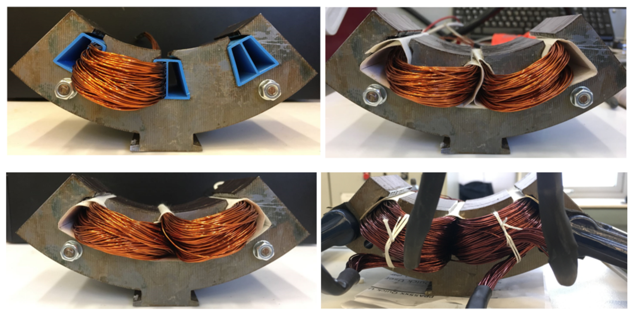
Figure 10 shows the randomly-wound experimental motorettes.
Table 6 lists the comparison of the losses in the motorettes and the Total/DC loss ratio in the winding for the three CFF considered. In
Table 6, the columns under ‘Measured Total Losses (W)’ represent the measured total losses in the motorette for the CFF for different frequencies supplied. The columns under ‘Losses in Winding’ represent the losses in the winding. This includes the losses in the auxiliary components (considered as DC losses), i.e., the losses in the end-winding, the connecting cables and the lead wires. The ‘Losses in Winding’ are calculated by subtracting the core loss value calculated using FEA from the measured total loss of the motorette at the different frequencies. The columns under Total/DC Loss (Winding) represent the Total/DC loss ratio in the windings. Again, the losses at 20 Hz are considered as baseline DC loss values.
This experimental result analysis shows that at lower frequencies the relationship between the CFF and AC losses in the winding is insignificant. However, at high frequencies (>500 Hz), as the CFF increases the AC losses in the winding increase. For instance, when the supplied frequency is 1500 Hz, the Total/DC loss ratio in the windings with 40% CFF is approximately 35% higher than the Total/DC loss ratio with 20% CFF. While in the presented cases the higher filling factor still yields the lowest net losses, it can be clearly deduced from the experimental measurements that for machines operating most of the time at high frequencies it may well be more efficient/economical to use a lower CFF.
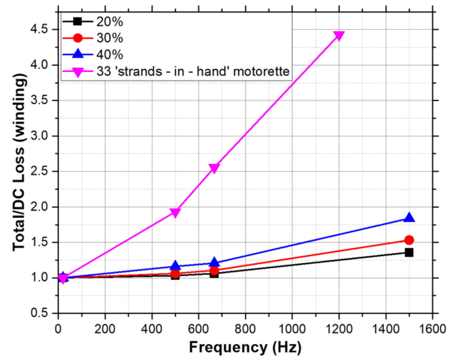
Figure 11 shows the comparison of the Total/DC loss ratio in the winding for 20%, 30% and 40% CFF along with the Total/DC loss ratio in the winding of the 33 ‘strands-in-hand’ motorette, which corresponds to the actual motor. For the motorette with 33 ‘strands-in-hand’, the total losses in the winding are 80 W when the frequency is 1200 Hz. In addition, when compared to the 40% CFF, the motorette with 33 ‘strands-in-hand’ has a CFF of 44.5%, which is 11.25% higher. However, with a smaller strand diameter, the total/DC loss ratio is approximately 4.42 when the supply frequency is 1200 Hz compared to 1.7 for the motorette with 18 thicker ‘strands-in-hand’. This is due to the greater circulating current effects in the motorette with the higher number of thinner parallel strands.
6. Segregation of Losses
The losses in the winding can be segregated as DC loss, skin and proximity (strand level) loss and circulating current (bundle level) loss. It can be represented as:
To study the individual contribution of the loss components, three arrangements of bundles are considered, namely: (a) ARR1, (b) ARR2 and (c) ARR3 as shown in
Figure 12. Here, each colour represents a bundle, and strands of the same colour represent strands-in-hand of each bundle. To eliminate the bundle level losses (at simulation level) arising from circulating currents in the bundle, each strand is supplied with its own current source to guarantee even distribution, as shown in
Figure 13 and
Figure 14.
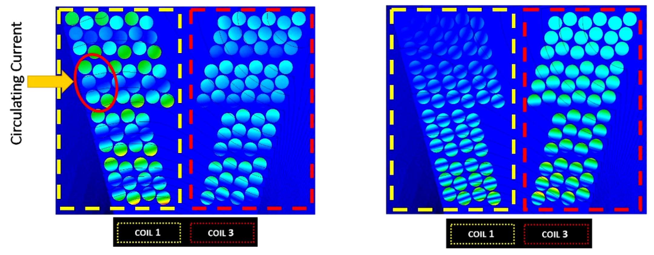
Figure 15 shows the current density (J) comparison at a given instant of time for the models with a single supply source and multi-source supply connected to each individual strand. It is evident from
Figure 15 that the circulating current effect can be minimized/eliminated at simulation level by this approach. Thus, the DC, the skin and the proximity effect (strand level) components of the winding loss are dominant in multi-source current analysis.
Using this methodology, the losses are segregated into their constituent components.
Figure 16 shows the comparison of segregated losses for the three aforesaid bundle arrangements. The strand level loss component (skin and proximity effect loss) remains nearly identical. However, the bundle level loss (circulating current loss) is greatly influenced by the shape of the bundle. This is caused by the distribution of leakage flux inside the slot and uneven flux linkage by the strands-in-hand.
7. Conclusions
High frequency AC losses in electric machines with non-transposed conductors are notoriously hard to predict and tricky to manage. This paper, which follows up from earlier research presented by the authors in [
18], verifies experimentally that AC losses can be calculated with accuracy (less than 10% difference up to 1.5 kHz) if the strand positions in the slot are controlled to be at the same coordinates as the FEA model. With the aforementioned baseline verification established, it has been shown using experimental motorettes that the exact positions of the strands in a conductor are not vital as long as the conductor shapes maintain the desired shape. This is an important development to the authors’ earlier work [
18] showing that a simplified and easier to implement solution involving conductor shape control can still yield significant benefits in AC loss reductions. The solution proposed in this paper results in a significant reduction in the time required for winding a machine compared to the solution in [
18]. Although an EV machine with concentrated type winding was used as basis of the analyses, the loss mitigation technique presented is applicable to all high frequency machines using mush winding (concentrated or distributed winding). The analyses presented in both [
18] and this paper are at a lower technology readiness level. However, with the advancement of 3D printing technology, the solutions can be improved towards a higher technology readiness level (TRL). In fact, controlling the bundle shape instead of the individual strand position is a significant simplification to the process of winding a machine. Adding a slot former reduces the effective copper fill factor and increases the DC component of the winding loss. The addition of a slot former also results in the increase of the component number in manufacturing the machine. However, given the lower TRL status of the proposed solution at this stage, an economic analysis at the level of high volume applications as suggested in the Advanced Propulsion Centre roadmap for electric machines [
28] should be performed. In the design of an electric machine, maximising the copper slot-filling factor is traditionally proposed to reduce losses in the winding. Using random-wound motorettes with varying copper filling factors and strand diameters, it has been experimentally shown that for high frequency machines (>1 kHz), counter-intuitive design choices such as using a lower copper fill factor and thicker strand diameters may be beneficial in achieving the highest overall efficiency. Finally, segregation of the winding losses into its individual components is shown at the simulation level.


 ,
, 


