Article

Design and Analysis of a Permanent Magnet Vernier Machine with Non-Uniform Tooth Distribution

1
Power Electronics and Electrical Drives Center, Harbin Institute of Technology (Shenzhen), Shenzhen 518055, China
2
Institute of Electromagnetic and Electronic Technology, Harbin Institute of Technology, Harbin 150001, China
*
Author to whom correspondence should be addressed.
Energies 2021, 14(22), 7816; https://doi.org/10.3390/en14227816
Submission received: 30 September 2021 / Revised: 17 November 2021 / Accepted: 18 November 2021 / Published: 22 November 2021
(This article belongs to the Special Issue All-Electric Propulsion Technology for Electrified Aviation)

Abstract

:
To improve the torque performance of the permanent magnet vernier machine in the direct-drive system for Unmanned Aerial Vehicle (UAV), this paper proposes the topology of non-uniform tooth distribution. This distribution, considering the additional flux harmonics, aims to contribute to torque improvement, whereas the cogging torque also increases at the same time. A phasors method is proposed to solve the issue caused by the non-uniform structure, adjusting the mechanic angle of each tooth reasonably to restrict the cogging torque. In addition, the non-uniform design is illustrated in detail, which includes the method of grouping the teeth, considering the factors of series pole ratio and winding layout. By using the three-dimensional finite element method, torque is significantly increased without additional torque ripple, which satisfies the desired design target.

1. Introduction

In recent years, the Unmanned Aerial Vehicle (UAV) [1] with long endurance has become a hot topic, where the reliable electrical drive systems with high-torque/power density machine have been discussed in research. As a competitive direct-drive machine, the permanent magnet vernier machine (PMVM) has recently been employed [2,3]. This is because the PMVM can cause the “flux modulation” by utilizing its magnetic field modulation teeth, which increases the composition of the flux harmonics to result in the features of low-speed and high-torque [2]. This characteristic is suitable for direct-drive, because of excluding the requirement of mechanical transmission gear box.
An axial-flux PMVM (AFPMVM) is discussed in this paper, which is a good choice used in the accessories drive in UAV for the high-torque density [4,5]. In [6], the torque contribution of stator and rotor components are presented by an AFPMVM of the MAGNUS type, which is also suitable to be used in in-wheel traction and wind turbines. Competitive axial-flux PMVM is proposed which has better performance on torque and power factor, and the analytical expressions of these machines are derived [7,8]. In addition, the electromagnetic force and eccentricity resulted by the axial-flux topology or unbalanced design have been discussed in [9,10,11]. In [12], a dual stator axial-flux PMVM with spoke type magnets for the flux focusing effect is proposed. Moreover, an axial-flux PMVM [13] which has high efficiency with dual-rotor of consequent-pole topology and one yoke-less concentrated-winding stator is proposed. The proposed rotor structure could reduce the weight, and improve the reliability and efficiency compared to the conventional one. In [14], a low-cost high-performance axial-flux vernier machine with the topology of dual-stator for electric vehicles is proposed, which could output high-torque density though the low-cost ferrite magnet used. A new multilevel Taguchi design optimization is proposed to increase the torque and power factor with less time consumption.
Many theoretical analyses of the production of low-speed and high-torque features in PMVM are illustrated in [2,15], as the detailed introduction for flux modulation and flux modulation poles (FMPs), which is beneficial to the design and optimization. In recent years, PMVMs are more and more widely researched due to their superior torque density and simple mechanical structure. Many novel PMVM topologies have been proposed, using traditional methods in PM machines to improve the performance, such as the topologies of double rotor [16], spoke PM array, axial-flux [17], etc. Based on the flux modulation, a topology with multiple harmonics is proposed by adjusting the position of FMPs in split-pole type PMVM [18]. However, the composition of magnetomotive force (MMF) caused by winding layout is not analyzed in detail, which is one key factor in machine design and harmonic utilization. In another analysis, winding MMF is proposed in similar topology, and the design method is given with a sinusoidal function [19] for the split-pole type PMVM. However, the extra cogging torque caused by non-uniform FMPs distribution is not discussed.
The cogging torque is a non-negligible problem in PM machines, especially in small low-power machines. To restrict the cogging torque, many structural methods are used in slot-tooth, such as optimized local sensitivity parameters [20], skewing [21], and so on. Magnets with notches are proposed to produce discrete skew effect which could reduce the cogging torque and torque ripples [12]. The authors of [22,23] propose that the total cogging torque is the summation of each slot, and eliminates the specific lower harmonics to reduce the cogging torque by offsetting the slots or magnets. This kind of method arranges the teeth or permanent magnets into special rules to restrict the cogging torque effectively, while the output torque will be dropped due to the production of additional flux harmonics. Modern vernier machines with competitive topology have relatively low torque ripple, such as below 5% in [6,7,17]. However, some strict dimension design constraints are required to follow in this research, so the basic surface-type PM vernier machine is adopted [4], where higher torque ripple would be generated by the un-selectable design of large tooth height and large slot width, to fulfill winding space and pole pair combination.
In this paper, an open-slot type PMVM with non-uniform tooth distribution is proposed to improve the torque performance, including both torque density and cogging torque. Torque density increases because of the multiple additional effective harmonics caused by flux modulation, which is cooperated with the MMF harmonics of winding. In another view, the cogging torque cannot be ignored in non-uniform tooth design, which is more complex than uniform structure. The tooth structure needs to consider the influence of cogging torque while providing additional torque. Therefore, a phasors method is used to restrict the additional cogging torque harmonics caused by non-uniform teeth, grouping all teeth into desired groups. The design method of non-uniform tooth distribution is given in detail, which is suitable for different series poles and winding layout of PMVM, especially for open-slot topology. Finally, main characteristics of the desired machine are verified by three-dimension finite element method (3D-FEM).

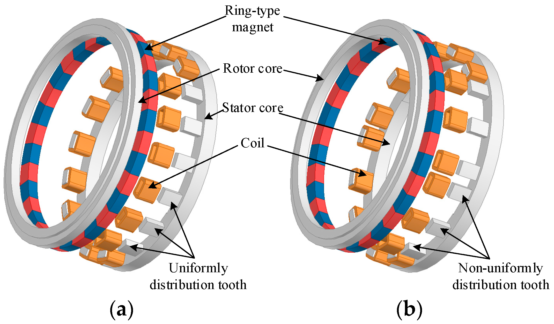
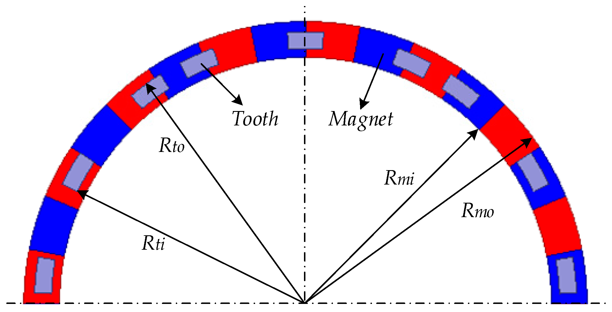
2. Topology and Parameters

An axial-flux PMVM, as one type of high torque density machine, is used to illustrate the principle of non-uniform distribution tooth design, which improves the torque density without additional cogging torque. The regular AFPMVM discussed in this paper, as shown in Figure 1a, is a typical open-slot PMVM with a ring-type surface magnet and toroidal coil. The target machine is designed for a direct-drive system with the rated speed of 50 rpm, which is extremely sensitive to torque performance [4]. Cogging torque is more serious in non-uniform tooth distribution, so this paper further illustrates the analysis in various aspects, including flux density, electromagnetic torque and cogging torque. The proposed machine with non-uniform distribution tooth is shown in Figure 1b, where the only difference between two topologies is the stator tooth distribution. The non-uniformly distributed tooth in the proposed machine is designed according to periodical regulation, considering the production of electromagnetic torque and cogging torque. The basic design parameters and constraints for both machines are shown in Table 1.
Figure 2 and Figure 3 present the top view and the expanded view of the proposed machine. One unit in a non-uniformly distributed tooth is illustrated in Figure 3, including three teeth symmetrically distributed along circumference direction, where θ1 is the width of main tooth, θ2 is the width of auxiliary tooth, θ3 is the width of slot between main and auxiliary tooth, θ4 is the width of width between two tooth units, τt is the tooth pitch between main and auxiliary tooth, and τs is the slot pitch between main and auxiliary slot. The rotor magnets are magnetized in parallel and the magnetization direction is shown in Figure 3. This structure divides all teeth into several identical units, and the centerline of each unit is equally spaced. In each unit, the teeth are symmetrically distributed based on the centerline. The main difference of two topologies is reflected in the tooth pitch between main and auxiliary tooth τt, aiming to improve electromagnetic torque and restrict cogging torque. All teeth are chosen in the same width to deal with the cogging torque, as introduced in Section 3. Using the non-uniformly distributed tooth in PMVM, the composition of airgap permeance harmonics is richer, which is decided by the number of units and tooth of each unit. Distinguished from the conventional PM machines, the harmonics are used to generate the net torque through magnetic field modulation effect in proposed PMVM.

3. Analysis of Proposed Topology

PMVM utilizes additional harmonics to realize the low-speed high-torque character by FMPs, which is called flux modulation effect. In open-slot PMVM, stator teeth play the role of FMPs to modulate the magnetic flux [2,6]. The torque performance of PMVM is sensitive to the situation of FMPs distribution, since the non-uniformly distributed tooth contributes to the distribution of airgap permeance. Compared with uniform tooth distribution, a non-uniform model has the advantage potential that brings the additional flux density harmonics to improve the torque, while also increases the harmonics of cogging torque. The proposed topology, according to a specific design method, performs well in terms of increasing torque without causing fluctuations, and is analyzed as follows. In the analytical model, essential assumptions have been made in advance as:
(1)
Relative permeability of PMs and coils is assumed to 1;
(2)
End effect and the magnetic field component on the radial direction are neglected.

3.1. No-Load Airgap Flux Density

Based on the equivalent magnetic circuit theory, the harmonic ingredients of magnetic flux density are decided by the MMF and airgap permeance, depending on the pole combination (p-Zr-Zs). The distribution of airgap permeance is determined by the arrangement of stator tooth in this kind of surface-type PM machine. In uniform tooth distribution with the same slot width, the distribution of airgap permeance takes one tooth pitch as a cycle, and is expressed in regular topology as
P ( θ ) = m = 0 P m cos ( m Z s θ )
where θ is the mechanical angle on stator, m is the order of the harmonic component of airgap permeance, and m = 0,1,2,3,..., Pm presents the amplitude of specific permeance harmonic of airgap in Fourier series expression, which are expressed in terms of slot geometries. However, considering the non-uniform tooth distribution, the different slot width causes the difference in minimum permeance in slot. The cycle of airgap permeance distribution is the width of one tooth unit, and the total number of cycles is Zf. As in the proposed topology, the airgap permeance of positive half cycle of a tooth unit is
P ( θ ) = { μ 0 g e             ( 0 θ 0.5 θ 1 0.3 θ 2 , 0.5 θ 1 + 1.3 θ 2 θ π / 6 0.8 θ 4 ) μ 0 g e ( 1 β 2 β 2 cos ( π 0.8 θ 2 ( θ 1 + θ 2 2 θ ) ) )     ( 0.5 θ 1 0.3 θ 2 < θ < 0.5 θ 1 + 1.3 θ 2 ) μ 0 g e ( 1 β 4 β 4 cos ( π 0.8 θ 4 ( π 6 θ ) ) )            ( π / 6 0.8 θ 4 < θ < π / 6 )
β i = 1 2 [ 1 ( 1 + ( π b i 360 g e ) 2 ) 1 2 ]
where βi is the coefficient to express the decline of permeance in slot, ge is the equivalent length of airgap, and bi is the width of ith slot [24]. Therefore, the distribution of airgap permeance per unit is shown in Figure 4, compared with the uniform model. Airgap permeance distribution in the proposed machine is more complicated than the regular one, which results in additional harmonics. The harmonic components are more abundant in proposed topology with non-uniform tooth distribution, expressed using Fourier series as
P ( θ ) = m = 0 P m cos ( m Z f θ )
Obviously, the component of harmonic is supplemented by lower harmonics. The MMF of airgap with Zr pole pairs of two topologies are identical, which is expanded in Fourier series as
F g ( θ , θ m ) = n = 1 , o d d F g n cos ( n Z r ( θ θ m ) )
where n is the order of the harmonic component of MMF, n = 1,3,5,7,..., the constants Fgn is the amplitude of specific harmonic in Fourier series expression, and θm is the rotor position relative to stator. In PMVM, the specific harmonic components in flux density also contribute to the useful output, especially at the non-uniform tooth distribution with more harmonics. The flux density [15] can be obtained as
B ( θ ) = P ( θ ) F ( θ , θ m ) = m = 0 n = 1 , o d d B | n Z r ± m Z f | cos ( | n Z r ± m Z f | θ n Z r θ m )
Considering the harmonic composition of airgap permeance in two topologies, the flux density introduced corresponding components synchronously, and they are listed in Table 2. The result ignores the higher harmonics of airgap permeance and MMF of magnets due to the lower amplitude. Compared with regular topology, the effect of non-uniform tooth distribution is evident. In addition, the contents of harmonic caused by non-uniform tooth distribution will increase with the reducing of the unit number.

3.2. Back-EMF and Electromagnetic Torque
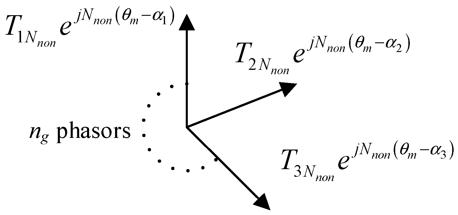
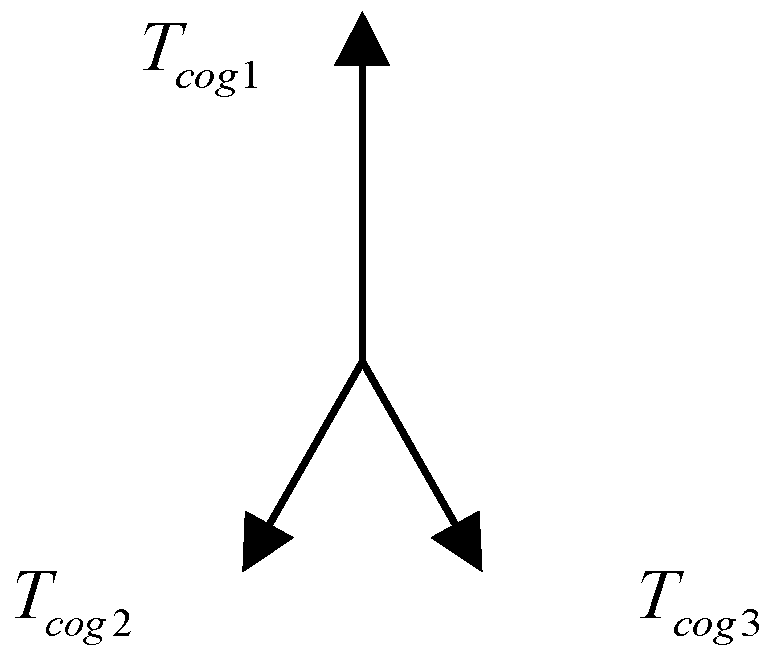
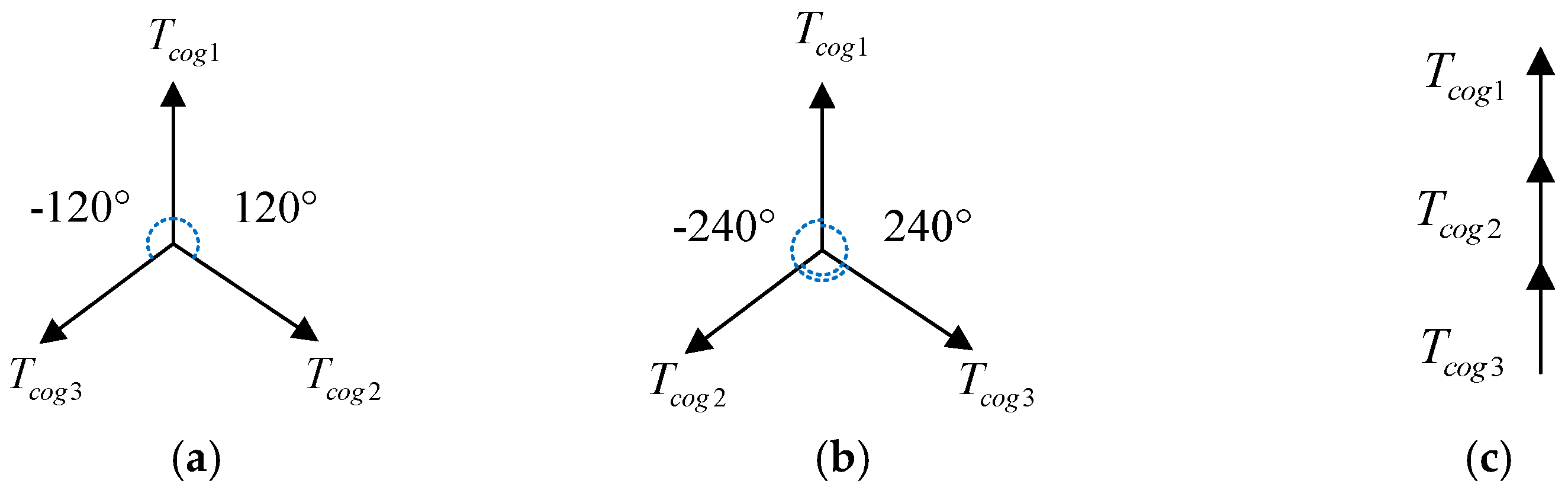
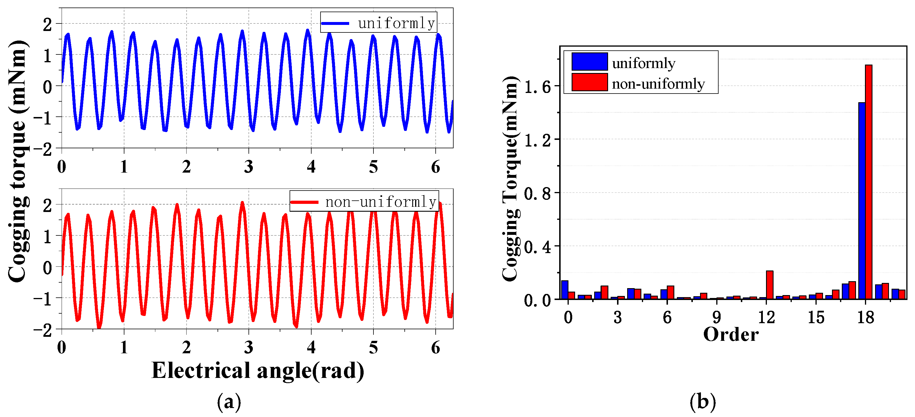
In the proposed machine with non-uniform tooth distribution, more harmonics contribute to machine performance. Considering all effective harmonics of flux density from magnet, the back-EMF in proposed AFPMVM is
E = N r m i d l ω Z r q i = 0 n g τ i π / p τ i B ( θ ) d θ = k w N r m i d l ω Z r m = 0 n = 1 , o d d B | n Z r ± m Z f | | n Z r ± m Z f | sin ( Z r ω t )
where N is the number of turns in one phase coils, ω is the rotor mechanical velocity, rmid is the average radius of one stator tooth which equals to (Rto + Rti)/2, l is the radial length, τi is the offset distance of each tooth, and kw is the main winding factor [4]. The schematic structure of each slot is shown in Figure 5, displayed by a 2D view that expands along the circumference direction in the proposed machine. The teeth at the same position in each unit tooth structure are assigned into one group, expressed in the same color and stripe. The stars of slot in machines are compared in Figure 6a,b, where the position of slots varies with the tooth structure. The phasors of back-EMF, determined by the phase of each section winding, are shown in Figure 6c.
The main winding factor kw is determined by the angle of slots τs. Another point worth noting is that the moving electrical angle of back-EMF is p times of the mechanical angle τs rather than Zr times, which is caused by the magnetic flux modulation effect in PMVM [25]. The electromagnetic torque is given as
T = e a i a + e b i b + e c i c ω = 3 I k w N r m i d l Z r 2 m = 0 n = 1 , o d d B | n Z r ± m Z f | | n Z r ± m Z f | sin ( Z r ω t )
where ea, eb, ec are the back-EMF of three phases, and ia, ib, ic, are phase excitation current. I presents the rms value of current.

3.3. Cogging Torque

The cogging torque is an inevitable issue in the PM machine, caused by interaction of stator teeth and slots. The classical methods to analyze cogging torque contain energy method, Maxwell tensor method and FEA. The energy method is to keep the magnetic flux of the motor constant and obtain the derivative of the energy stored in the airgap to get the overall effect of the cogging torque. Moreover, the accuracy of Maxwell tensor method is related to the selection of the integration path and the calculation of the flux density, while the accuracy of the energy method is greatly related to the selection of the angle increment, so the energy method is suitable to the target of considering the overall effect and choosing a suitable angle of tooth pitch between main and auxiliary tooth to reduce the cogging torque. Based on the airgap permeance and MMF [20,22], the expression of cogging torque is shown as
T c o g g i n g = W θ m = θ m 1 2 μ 0 V F 2 ( θ , θ m ) P 2 ( θ ) d V
where W is the magnetostatic energy and μ0 is air permeability. Considering the number of teeth and magnets, the number of cogging torque periods in one mechanical cycle is the least common multiple of teeth and magnets, expressed as
N = L C M ( Z s , 2 Z r )
where LCM is the least common multiple.
However, the number of cogging torque periods in one mechanical cycle is various in the proposed machine with non-uniform tooth distribution. Due to the addition permeance harmonics as shown in Equation (4), the number of cogging torque period in the proposed machine is expressed as
N n o n = L C M ( Z f , 2 Z r )
In general, Zs and Zr are selected as relatively prime numbers to restrict cogging torque. Therefore, the number of cogging torque period is decreased in non-uniform tooth distribution, where Zs is the multiple of Zf. At the same time, the amplitude of cogging torque increases, which is the disadvantage for non-uniform tooth distribution. In order to deal with the cogging torque in non-uniform tooth distribution, a phasors method is proposed by grouping teeth as in Figure 5. The number of groups is the same as the number of teeth in one unit. The cogging torque of total teeth is the sum of each group, which is verified by FEM in Figure 7. The key derivation of the cogging torque [20] of kth group could be expressed as
W = 1 2 μ 0 V B 2 d V = 1 2 μ 0 V F 2 ( θ , θ m ) P 2 ( θ ) d V = 1 2 μ 0 V B 2 ( θ , θ m ) G 2 ( θ ) d V = 1 4 μ 0 ( R 2 2 R 1 2 ) 0 2 π B 2 ( θ , θ m ) G 2 ( θ ) d θ
where R2 is the outer diameter of airgap and R1 is the inner diameter of airgap.
B 2 ( θ ) = B 0 + n = 1 B n cos [ 2 n p ( θ + θ m ) ] = α p B r 2 + n = 1 2 n π B r 2 sin n α p π cos [ 2 n p ( θ + θ m ) ] G 2 ( θ ) = G 0 + n = 1 G n cos ( n Z s θ )
= ( h m h m + g e ) 2 + n = 1 [ 2 n π ( h m h m + g e ) 2 sin ( n π n Z s b 0 2 ) ] cos ( n Z s θ )
From Equation (5), n = 1,3,5,7,… so Gn = Ksin(nZsb0), the number of cogging torque period is replaced by Nnon from Equation (11), so Gn = Ksin(nNnonb0). According to Equation (9), the cogging torque of kth group could be expressed as
T c o g k = i = 1 T i N n o n sin ( i N n o n b k 2 ) sin i N n o n ( θ m α k )
where TiNnon is the coefficient related to flux density components and bk and αk are the slot width and the mechanical offset angle for kth group tooth. In the proposed phasors method, the cogging torque of each group is expressed as phasors. Based on Equation (15), the amplitude and phase of each phasor are related to bk and αk, respectively. The specific harmonic of cogging torque could be eliminated by selecting the width and offset angle of group tooth reasonably, as shown in Figure 8. The sum of three cogging torque harmonic phasor is zero, which means that the total cogging torque excludes this harmonic. Considering the amplitude and phase of each phasor in Equation (15) and the symmetry, the condition for eliminating the ith harmonic is
sin ( i N n o n b 1 2 ) + 2 sin ( i N n o n b 2 2 ) cos ( N n o n τ t ) = 0
where b1 and b2 are the width of main and associate tooth, respectively.
The precondition of this method is that the sum of phasors is zero, while the combination of teeth without meeting this condition is invalid. A simplified method in this paper is used to avoid invalid situations, setting all teeth the same width and phasors evenly distributed in a circumference. Figure 8 is the cogging torque phasors diagram of the proposed machine with three groups of teeth. Setting the fundamental harmonic of cogging torque with a 120° different angle from each other and the same amplitude of phasors diagram, thus the total cogging torque of fundamental harmonic counteracts, as shown in Figure 9a. It is worth noting that the second harmonic also counteracts, while the third harmonic is in a superimposed condition, which is the same as the regular machine with uniform tooth distribution. Considering the symmetry of three phasors, a 240° angle is also a feasible angle to control total cogging torque as 120°, while a 360° different angle causes all cogging torque harmonics to be tripled. In order to realize the above angle, the tooth pitch between main and auxiliary tooth trends to be set as
τ t = k 120 ° N n o n ( 14 , 15 , 16 , 17 , 18 , 19 ) × 1.25 °
where, k is the number of phasor offset angle (120° cogging torque fundamental harmonic angle) for the auxiliary tooth. In order to exclude the 360° offset angle, k should not be an integer multiple of 3.
Figure 10 is the comparison of the cogging torque of different τt calculated from Equation (17), which shows that the cogging torque of k = 15 and k = 18 is significantly larger than that of k = 14, 16, 17 and 19. This is because that three phasors are superimposed when k = 15 and 18, while the phasors are counteracted each other when k = 14, 16, 17 and 19. Therefore, when the feasible k is selected, the cogging torque could be eliminated with the additional harmonic caused by non-uniform tooth distribution.

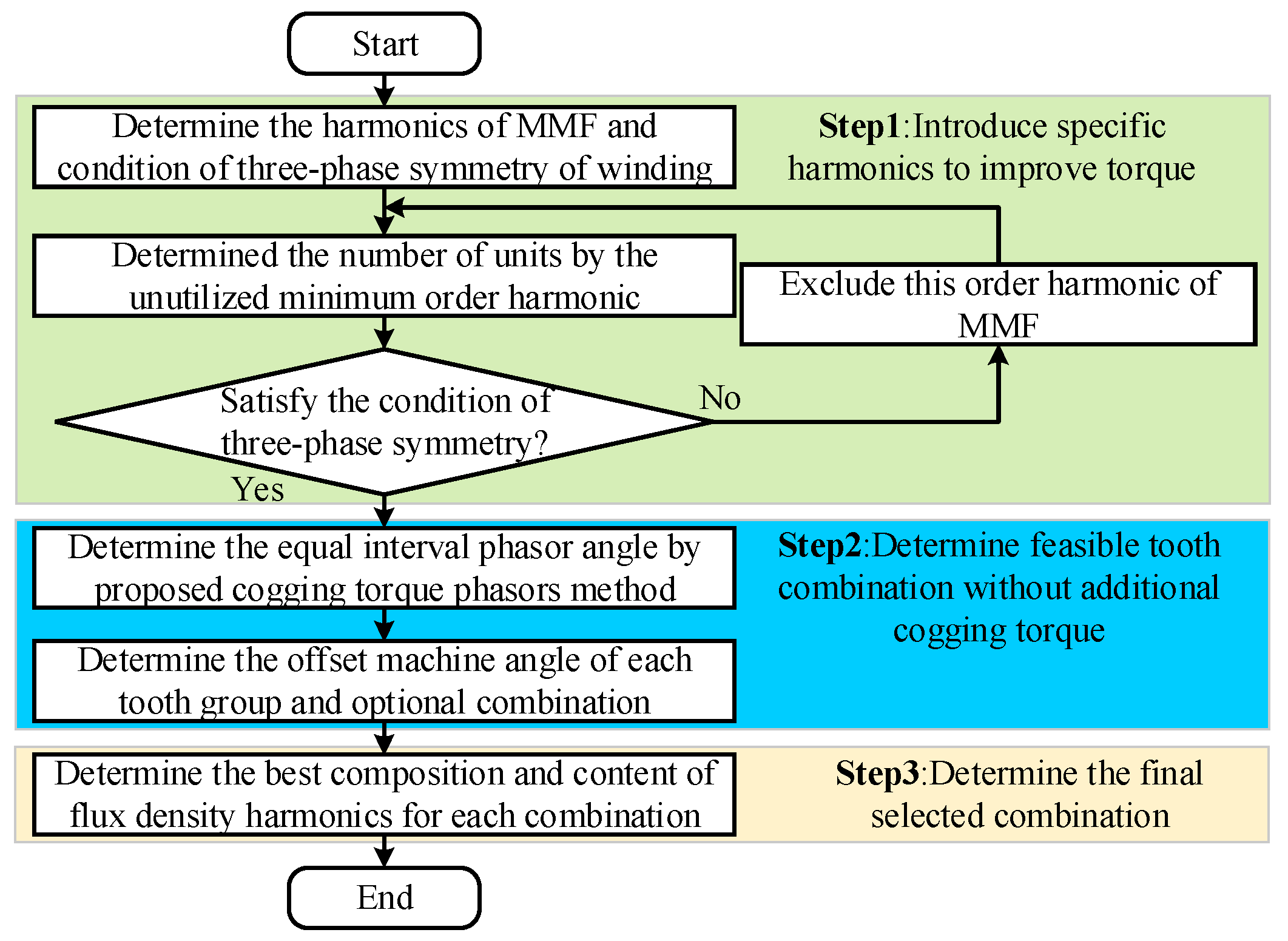
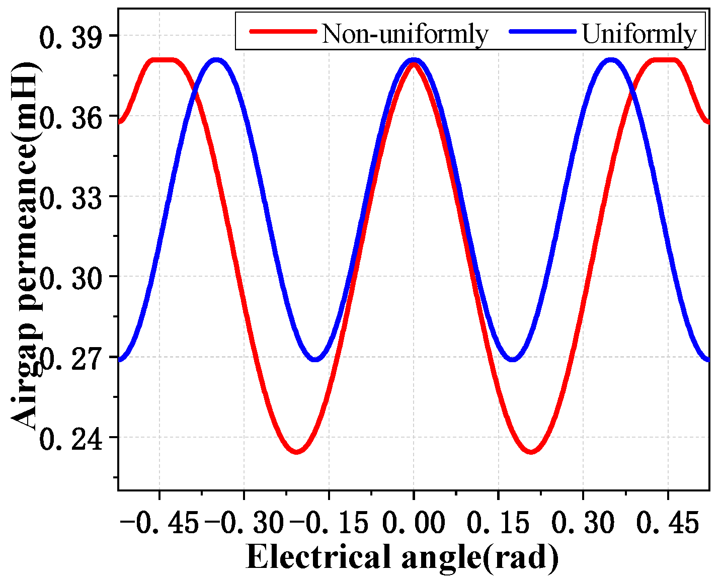
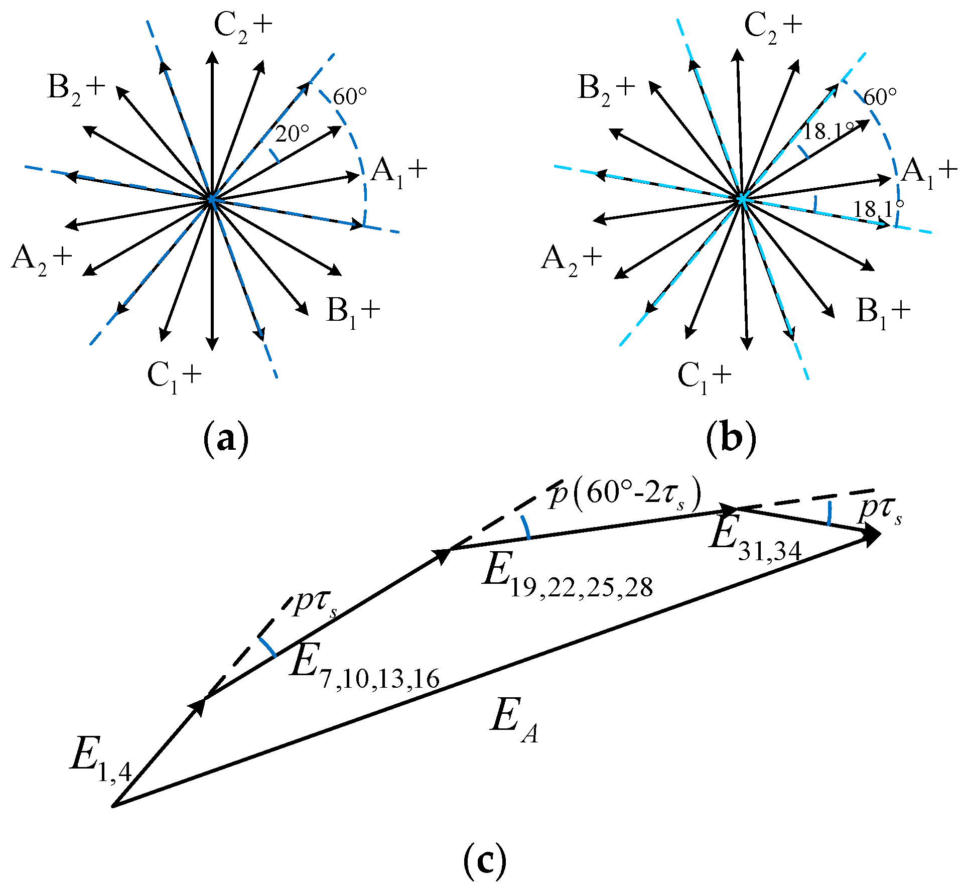
4. Design Method for Non-Uniform Tooth Distribution

The proposed non-uniform tooth distribution structure introduces additional flux density harmonics by changing the distance between teeth to improve performance. The non-uniform tooth distribution structure divides all teeth into several units for the desired harmonics, while the number of units are designed based on the series poles of PMVM and the winding type. Considering the basic principle of PMVM, the net torque comes from the interaction of corresponding orders flux density of magnets and MMF of winding [1]. The net torque could be expressed as
T = k T k w n F c n B P M n
where Fcn and BPMn are the nth order harmonics of winding MMF and magnet flux density, respectively, and kwn is the nth order of winding factor.
This situation is important to the non-uniform tooth distribution, where the introduced flux harmonics need to correspond to MMF of winding. The ingredient of MMF harmonics due to coil current is decided by the stator winding layout [26]. Based on the principal as shown in Equation (18), the layout with richer harmonic contents has the superiority in non-uniform tooth distribution to increase the net torque, while it has a disadvantage of larger cogging torque. The other point is that the three-phase winding should be symmetrical in open-slot PMVM with non-uniform tooth distribution. In order to compare two PMVMs fairly, the number of turns per coil are kept the same at 88 for comparison, which results in different winding packing factor of 0.4 in slot A marked in Figure 3 but maximum 0.75 in some small slots, such as slot B marked in Figure 3 under a strict dimension constraint. The design approach of non-uniform tooth distribution is shown in Figure 11, the steps are introduced as follows.
Step 1: Introduce the specific airgap permeance harmonics. In order to produce the expected harmonics order, each unit is set to a symmetric equidistant distribution. The non-uniform tooth distribution results in additional airgap permeance harmonics to generate specific flux density harmonics, which corresponds to MMF harmonics due to coil current. In the three-phase machine with double-layer concentrated windings, the MMF due to coil current can be expressed as in [27].
F c ( θ m , t ) = F c 1 [ k = 0 k w ( 3 k + 1 ) 3 k + 1 cos { ( 3 k + 1 ) p θ m ω i t } + k = 1 k w ( 3 k 1 ) 3 k 1 cos { ( 3 k 1 ) p θ m + ω i t } ]
where Fc1 is the amplitude of the fundamental harmonic of winding MMF, and ωi is the angular frequency of the excitation current. Based on the Equations (6), (18) and (19), the harmonic orders of flux density in no-load condition and MMF due to coil current trend to satisfy the relationship of
| n Z r ± m Z f | = p ( 3 k ± 1 )
To ensure the amplitude of each harmonic, the values of n, m and k are selected as small values as shown in Table 3, expressing the coordination of lower harmonics for non-uniform tooth distribution. The p and Zr order harmonics are utilized in regular PMVM, while other lower harmonics are wasted because of the lack of corresponding field harmonics. Therefore, in non-uniform tooth distribution, the second lower harmonic (2p order) of Fc is selected to utilize, cooperating with the order Zfn of airgap permeance harmonic expressed as
Z f n = Z r 2 p = Z s 3 p
where Zfn is the number of airgap permeance harmonic order required instead of the lowest. The lowest order of airgap permeance harmonic is the same as the number of units in non-uniform tooth distribution, and can be expressed as
Z f = G C D ( Z f n , Z s )
where GCD is the greatest common divisor. The last target of step 1 is to ensure the three-phase symmetry of windings, which is the key point in a three-phase machine. If the symmetrical condition is not satisfied, the second low order of Fc requires to be discarded and the third low one is used to calculate Zf, which would cause the partial waste of winding MMF harmonics.
Step 2: Eliminate additional cogging torque harmonics. After determining the basic structure of non-uniform tooth distribution, including the number of units Zf and tooth number of each unit ng, the proposed phasors method is used to eliminate additional harmonics of cogging torque. The Nnonth order phasors diagram for tooth groups is shown in Figure 12, which includes ng phasors. By shifting the phasors in a uniform angle, the introduced harmonics of cogging torque can be eliminated. The interval angle of Nnonth order cogging torque harmonic is expressed as
α n g = j 360 ° n g
where j is an integer and cannot be selected as a multiple of ng to avoid all harmonics in superimposed states based on the phasors method. Furthermore, due to the symmetry of multiple order phasors, all order harmonics except ngNnon times are eliminated in theory. In order to build the above angle, the tooth pitch between two teeth should be set as
τ t = α n g N n o n
Combined with a suitable tooth position, the additional cogging torque harmonics could be eliminated. In addition, the proposed phasors method has the advantage for a machine with non-coprime combination of Zs and Zr, which causes the decrease of frequency and the increase of amplitude for cogging torque. Using the proposed method, the original lower order and their multiple harmonics are also eliminated. Therefore, the cogging torque in non-uniform tooth distribution is improved compared to the uniform one in this situation. Finally, using the analytical or FEM method for all combinations of teeth, the performance is estimated and compared to obtain an optimal result.

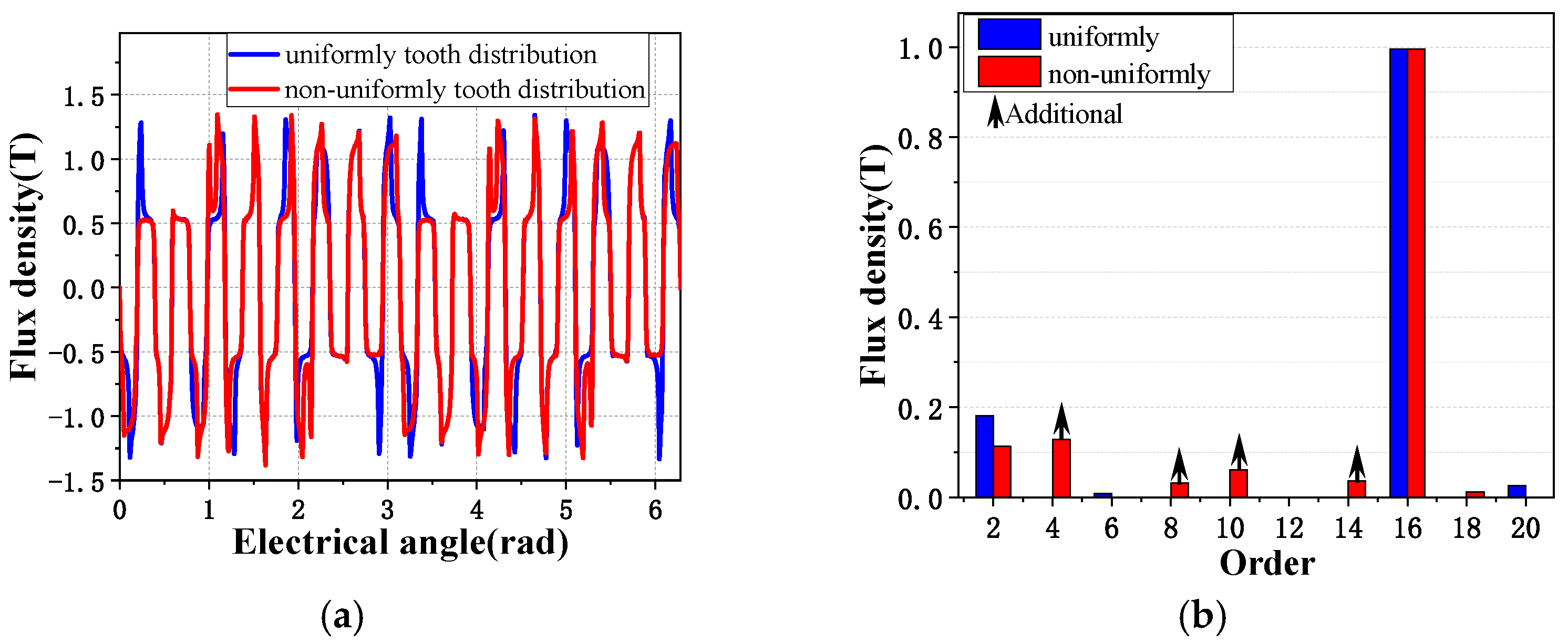
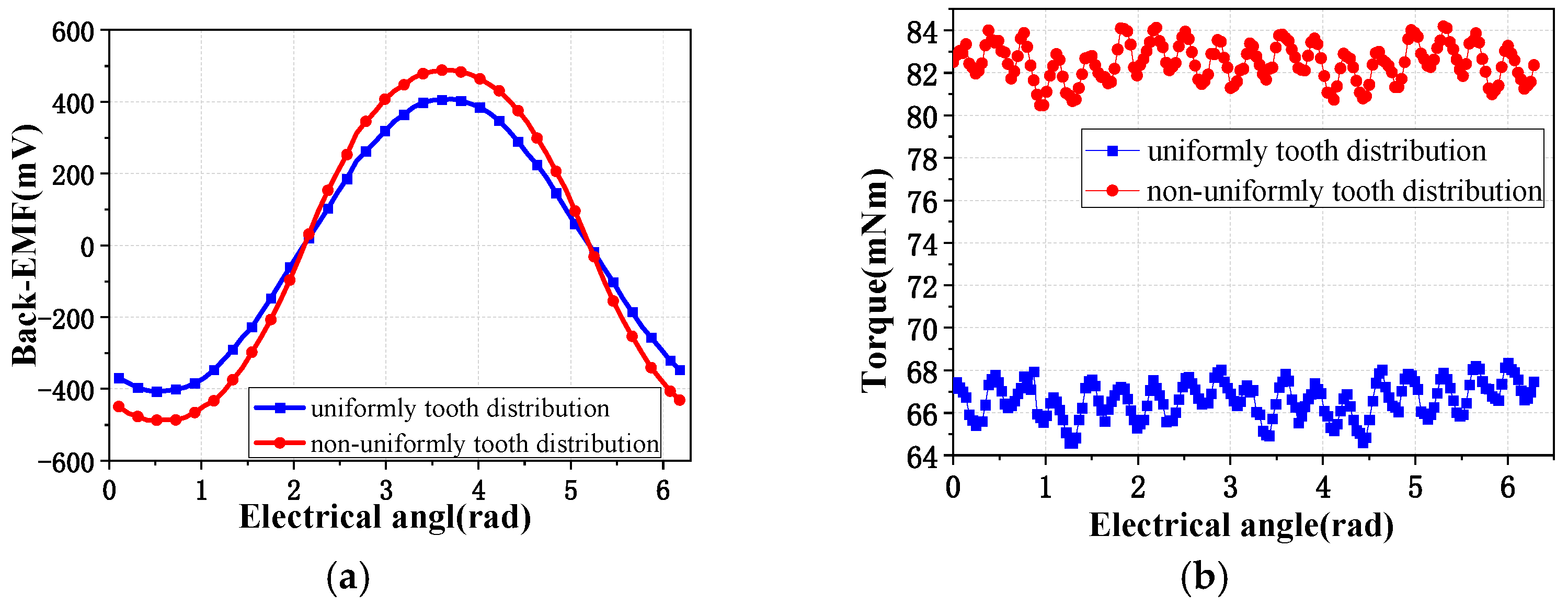
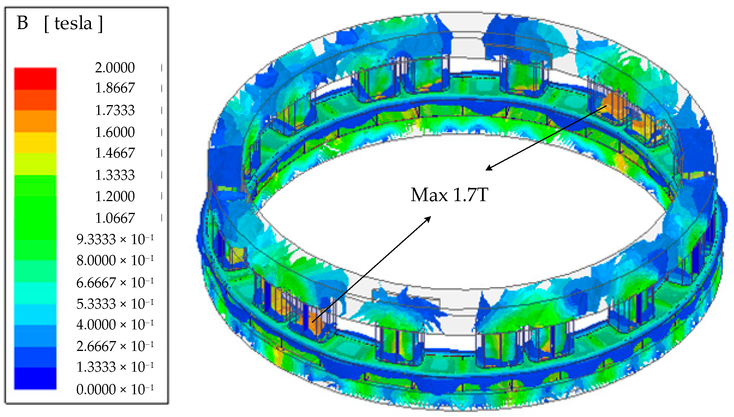
5. FEM Results of Proposed Topology

The proposed machine parameters with non-uniform tooth distribution considering the suitable width of tooth and tooth pitch between main and auxiliary tooth, is presented in Table 4. The selected τt corresponding to the number of k in Equation (17) is 19. In order to verify the advantage of the proposed machine, FEM is used to verify machine performance. A reasonable flux density distribution by 3D-FEM is shown in Figure 13, where the maximum flux density is around 1.7T in the tooth with full-load operation. The comparison of airgap flux density in no-load condition between two topologies is shown in Figure 14a,b. Compared with the uniform model, the composition of harmonics is richer with the additional harmonics, which agrees with the analytical results by the same orders (4,8,10,14) of the additional harmonics in Table 2. These harmonics have a positive effect on machine performance, which represents the superiority of non-uniform tooth distribution. It is worth noting that the second harmonic is slightly reduced, which causes the decrease of output. However, the total effect produced by all harmonics has significant improvement.
The back-EMF is simulated in no-load condition at 50 rpm in Figure 15a. The electromagnetic torque is compared in Figure 15b with the rated current of 0.4Arms. Table 5 compares the performance of two topologies, showing that the proposed machine with non-uniform tooth distribution has a relatively improved performance. Back-EMF and average torque are improved by 24.7% and 23.9%, respectively. Even with additional flux density harmonics, the torque ripple ratio of proposed topology still drops, due to the increase of average torque. The contrast of cogging torque is shown in Figure 16. Figure 16a shows that the cogging torque only increases slightly, proving the effectiveness of the proposed phasors method. The FFT results in Figure 16b present that the 6th harmonic is not increased due to the offset of grouping phases, while the 12th and 18th components have been slightly increased caused by the optimization of offset angle.

6. Conclusions

This paper proposes a non-uniform tooth distribution for the open-slot PMVM to improve the torque performance, by introducing additional harmonics in airgap. According to the magnetic field modulation effect in PMVM, more abundant flux harmonics are produced to cooperate with the corresponding harmonics of winding MMF, which improves the net torque. The torque of the proposed machine increased 24% more than the regular machine. On the other hand, the proposed machine has resolved the additional cogging torque harmonics introduced by non-uniform tooth distribution by using the proposed phasors method, which is also suitable for the traditional PM machines. Moreover, the design method of non-uniform tooth distribution is presented in detail, which selects the suitable number of units in the non-uniform tooth distribution to result in the desired harmonics of magnetic flux and ensure the balanced windings. The additional harmonics of cogging torque are restricted by distributing the position of the tooth reasonably, which has additional advantage for the PMVM considering pole pair combination. Finally, the machine performance is analyzed and compared by FEM results, which verifies the desired improved torque performance in the proposed machine with expectation.

Author Contributions

Conceptualization, writing-original draft F.Z.; data curation, M.C.; software, E.T.; investigation, L.L. All authors have read and agreed to the published version of the manuscript.

Funding

This research received no external funding.

Institutional Review Board Statement

Not applicable.

Informed Consent Statement

Not applicable.

Data Availability Statement

Not applicable.

Acknowledgments

This work was supported in part by Guangdong Basic and Applied Basic Research Foundation 2021A1515010754, and the Basic Research Plan in Shenzhen City (Grant No. JCYJ20180507181539943 and JCYJ20190806142618203).

Conflicts of Interest

The authors declare no conflict of interest.

References

  1. Zhang, C.; Li, L.; Guo, Q. Parameter analysis of power system for solar-powered unmanned aerial vehicle. Appl. Energy 2021, 295, 117031. [Google Scholar] [CrossRef]
  2. Toba, A.; Lipo, T. Generic torque-maximizing design methodology of surface permanent-magnet vernier machine. IEEE Trans. Ind. Appl. 2000, 36, 1539–1546. [Google Scholar]
  3. Li, J.; Chau, K.; Jiang, J.; Liu, C.; Li, W. A new efficient permanent-magnet vernier machine for wind power generation. IEEE Trans. Magn. 2010, 46, 1475–1478. [Google Scholar] [CrossRef]
  4. Zhao, F.; Kim, M.; Kwon, B.; Baek, J. A small axial-flux vernier machine with ring-type magnets for the auto-focusing lens drive system. IEEE Trans. Magn. 2016, 52, 1–4. [Google Scholar] [CrossRef]
  5. Xiao, L.; Li, J.; Qu, R.; Jia, S.; Guo, S. Windings Configurations for Vernier Reluctance Dual-Stator Inner-Rotor Axial Flux Machines. In Proceedings of the 18th International Conference on Electrical Machines and Systems (ICEMS), Pattaya, Thailand, 25–28 October 2015; pp. 1797–1802. [Google Scholar]
  6. Kesgin, M.G.; Han, P.; Lawhorn, D.; Ionel, D.M. Analysis of Torque Production in Axial-flux Vernier PM Machines of the MAGNUS Type. In Proceedings of the IEEE International Electric Machines & Drives Conference (IEMDC), Hartford, CT, USA, 17–20 May 2021. [Google Scholar]
  7. Zhang, R.; Li, J.; Qu, R.; Li, D. Analysis and Design of Triple-Rotor Axial-Flux Spoke-Array Vernier Permanent Magnet Machines. IEEE Trans. Ind. Appl. 2018, 1, 244–253. [Google Scholar] [CrossRef]
  8. Fukai, D.; Shimomura, S. Integrated Radial and Dual Axial-Flux Variable Reluctance Vernier Machine. In Proceedings of the IECON, Dallas, TX, USA, 29 October–1 November 2014. [Google Scholar]
  9. Wang, Q.; Zhao, F.; Yang, K. Analysis and Optimization of the Axial Electromagnetic Force for an Axial-Flux Permanent Magnet Vernier Machine. IEEE Trans. Magn. 2020, 57, 1–5. [Google Scholar] [CrossRef]
  10. Deng, W.; Zuo, S. Axial force and vibroacoustic analysis of externalrotor axial-flux motors. IEEE Trans. Ind. Electron. 2018, 65, 2018–2030. [Google Scholar]
  11. Liu, G.; Chen, M.; Zhao, W.; Chen, Q.; Zhao, W. Design and analysis of five-phase fault-tolerant interior permanent-magnet vernier machine. IEEE Trans. Appl. Supercond. 2016, 26, 1–5. [Google Scholar] [CrossRef]
  12. Bilal, M.; Ikr, A.; Fida, A. Performance improvement of dual stator axial flux spoke type permanent magnet vernier machine. IEEE Access 2021, 9, 64179–64188. [Google Scholar] [CrossRef]
  13. Gorginpour, H.H. Analysis and design considerations of an axial-flux dual-rotor consequent-pole vernier-PM machine for direct-drive energy conversion systems. IET Renew. Power Gener. 2020, 14, 211–221. [Google Scholar] [CrossRef]
  14. Liu, C.; Wang, K.; Wang, S. Analysis and design optimization of a low-cost axial flux Vernier machine with SMC cores and ferrite magnets. Electr. Eng. 2020, 102, 2595–2604. [Google Scholar] [CrossRef]
  15. Kim, B.; Lipo, T. Operation and design principles of a PM vernier motor. IEEE Trans. Ind. Appl. 2014, 50, 3656–3663. [Google Scholar] [CrossRef]
  16. Niu, S.; Ho, S.; Fu, W.; Wang, L. Quantitative comparison of novel vernier permanent magnet machines. IEEE Trans. Magn. 2010, 46, 2032–2035. [Google Scholar] [CrossRef]
  17. Zhao, F.; Lipo, T.; Kwon, B. A novel dual-stator axial-flux spoke-type permanent magnet vernier machine for direct-drive applications. IEEE Trans. Magn. 2014, 50, 1–4. [Google Scholar] [CrossRef]
  18. Zou, T.; Li, D.; Qu, R.; Jiang, D.; Li, J. Advanced high torque density PM vernier machine with multiple working harmonics. IEEE Trans. Ind. Appl. 2017, 53, 5295–5304. [Google Scholar] [CrossRef]
  19. Jang, D.; Chang, J. Influences of winding MMF harmonics on torque characteristics in surface-mounted permanent magnet vernier machines. Energies 2017, 10, 580. [Google Scholar] [CrossRef] [Green Version]
  20. Zhu, L.; Jiang, S.; Zhu, Z.; Chan, C. Analytical methods for minimizing cogging torque in permanent-magnet machines. IEEE Trans. Magn. 2009, 45, 2023–2031. [Google Scholar] [CrossRef]
  21. Ueda, Y.; Takahashi, H. Transverse-flux motor design with skewed and unequally distributed armature cores for reducing cogging torque. IEEE Trans. Magn. 2017, 53, 1–5. [Google Scholar] [CrossRef]
  22. Hwang, S.; Eom, J.; Hwang, G.; Jeong, W.; Jung, Y. Cogging torque and acoustic noise reduction in permanent magnet motors by teeth pairing. IEEE Trans. Magn. 2000, 36, 3144–3146. [Google Scholar] [CrossRef]
  23. Zhu, Z.; Ruangsinchaiwanich, S.; Ishak, D.; Howe, D. Analysis of cogging torque in brushless machines having nonuniformly distributed stator slots and stepped rotor magnets. IEEE Trans. Magn. 2005, 41, 3910–3912. [Google Scholar] [CrossRef]
  24. Zhu, Z.Q.; Howe, D. Instantaneous magnetic field distribution in brushless permanent magnet DC motors. III. Effect of stator slotting. IEEE Trans. Magn. 1993, 29, 143–151. [Google Scholar] [CrossRef]
  25. Yang, J. Quantitative comparison for fractional-slot concentrated-winding configurations of permanent-magnet vernier machines. IEEE Trans. Magn. 2013, 49, 3826–3829. [Google Scholar] [CrossRef]
  26. Cros, J.; Viarouge, P. Synthesis of high performance PM motors with concentrated windings. IEEE Trans. Energy Convers. 2002, 17, 248–253. [Google Scholar] [CrossRef]
  27. Zou, T.; Qu, R.; Li, D.; Jiang, D. Synthesis of Fractional-Slot Vernier Permanent Magnet Machines. In Proceedings of the International Conference on Electrical Machines (ICEM), Lausanne, Switzerland, 4–7 September 2016; pp. 911–917. [Google Scholar]
Figure 1. Configuration of the proposed AFPMVM: (a) regular topology (b) proposed topology.
Energies 14 07816 g001
Figure 2. Top view of half proposed AFPMVM.
Energies 14 07816 g002
Figure 3. Expanded view of one tooth unit in non-uniform distribution.
Energies 14 07816 g003
Figure 4. Analytical airgap permeance in one unit of two different tooth distribution topologies.
Energies 14 07816 g004
Figure 5. Equivalent 2D machine model (expanded at middle radius).
Energies 14 07816 g005
Figure 6. Star of slots and resultant phasors of target machines: (a) regular machine with τt = 20°; (b) proposed machine with τt = 18.1°; (c) resultant phasors of back-EMF.
Energies 14 07816 g006
Figure 7. Cogging torque verification of proposed method by FEM: (a) each group (b) sum comparison.
Energies 14 07816 g007
Figure 8. Cogging torque phasors diagram.
Energies 14 07816 g008
Figure 9. Cogging torque phasor diagram for equal angle: (a) Nnon orders (b) 2 Nnon orders (c) 3 Nnon orders.
Energies 14 07816 g009
Figure 10. Cogging torque with different tooth pitch by FEM.
Energies 14 07816 g010
Figure 11. Design approach of non-uniform tooth distribution.
Energies 14 07816 g011
Figure 12. The phasor of cogging torque for ng group tooth.
Energies 14 07816 g012
Figure 13. Flux density distribution of the 3D-FEM in on-load condition.
Energies 14 07816 g013
Figure 14. Comparison of airgap flux density by FEM: (a) flux density waveform; (b) spectra of FFT.
Energies 14 07816 g014
Figure 15. Comparison of performance at 50 rpm by FEM: (a) back-EMF; (b) electromagnetic torque with rated 0.4 Arms current.
Energies 14 07816 g015
Figure 16. Cogging torque contrast by FEM. (a) Cogging torque. (b) Spectra of FFT.
Energies 14 07816 g016
Table 1. Machine parameters and constraints.
Item-Item-
Stator
tooth
Outer radius Rto31.75 mmMagnetOuter radius Rmo32.95 mm
Inner radius Rti29.75 mmInner radius Rmi28.8 mm
Tooth height h5.9 mmHeight gm3 mm
Airgap length g0.3 mmNo. of rotor pole-pairs Zr16
No. of stator slots Zs18Winding pole-pairs p2
Magnet materialNdFeBBr1.23 T
Table 2. Summarization of Main Flux Density Harmonics.
Spatial Harmonic Order of the Proposed Machine
MMF (nZr)Permeance (mZf)Flux Density (|nZr ± mZs|)
16016
610
124
182
248
3014
Table 3. Summarization of main harmonics for non-uniform tooth distribution.
nMMF of WindingFlux DensityMMF of
Magnets
Permeance
OrderEquation (22)
0ppZsZrZrZs
12 p2 pZrZfnZfn
4 p4 pZfn + 2ZfZrZfn + 2Zf
25 p5 pZr−(ZfnZf)ZfnZf
7 p7 pZfn + 3ZfZrZfn + 3Zf
38 p8 pZr−(Zfn−2Zr)Zfn−2Zf
10 p10 pZfn + 4ZfZrZfn + 4Zf
Table 4. Parameter comparison of one unit tooth structure.
ItemsUnitRegularProposed
No. of tooth units Zf--6
No. of tooth in each unit ng--3
Width of main tooth θ1deg7.877.87
Width of auxiliary tooth on the left θ2deg12.1315.93
Width of slot between main and auxiliary tooth θ3deg7.877.87
Tooth pitch between main and auxiliary tooth τtdeg2023.8
Slot pitch between main and auxiliary slot τsdeg2018.1
Table 5. Comparison of two topologies.
MethodBack-EMF (mV)Torque (mNm)Torque
Ripple
Cogging Torque
Peak to Peak (mNm)
Regular machine288.5966.65.7%3.27
Proposed machine359.7882.54.5%3.89
Increment24.7%23.9%-18.9%
Publisher’s Note: MDPI stays neutral with regard to jurisdictional claims in published maps and institutional affiliations.

