Article

Unified Strategy for Fault-Tolerant Operation of MMC with Multiple SMs Failure Based on SMs Grouping Management

College of Electrical Engineering, Zhejiang University, Hangzhou 310027, China
*
Author to whom correspondence should be addressed.
Energies 2022, 15(15), 5694; https://doi.org/10.3390/en15155694
Submission received: 30 May 2022 / Revised: 12 July 2022 / Accepted: 25 July 2022 / Published: 5 August 2022

Abstract

:
Modular multilevel converter (MMC) is distinguished by its modularity. In order to improve its reliability and avoid unscheduled maintenance, it requires the MMC to continue operating even though some of its submodules (SMs) have failed. In this paper, a grouping management method of SMs in MMC is first presented where every six SMs are conceptually grouped into a virtual subunit (SU), and on this basis, a simplified space vector modulation (SVM) implementation is developed. Then, the fault-tolerant solutions are proposed by investigating the post-fault operation of the MMC based on the virtual SU concept. It is analyzed that the SU failures can be categorized into three basic types, according to the phase where the failed SMs are located, and also multiple SM failures can be decomposed into one or multiple basic fault types. In this way, the fault-tolerant solutions are unified regardless of the number of faulty SMs. Further, the sorting capacitor voltage control is combined into the proposed methods to balance all of the SM capacitor voltages. With the proposed fault-tolerant method, the amplitude and THD of the line voltages are almost unchanged under fault conditions when compared with normal operations. The simulation and experiment verify the propositions.

1. Introduction

Modular multilevel converters (MMCs) have become more and more attractive for medium/high voltage applications, especially high-voltage direct current transmission (HVDC) and medium-voltage motor drives, due to their modularity and extensibility [1,2,3]. However, since there are a huge number of SMs in MMC (Figure 1), they are loaded against their reliability [4]. It is not until MMC can permit one or some of its broken SMs that the whole system’s reliability would be greatly improved. Failure types of SMs, failure rates and failure consequences have been shown in [5]. All of these faults will affect the normal operation of MMCs. Therefore, it is necessary to provide suitable fault-tolerant (FT) methods to avoid unscheduled shutting down [6,7,8].
To enhance the fault-tolerant capability of MMC, several strategies have been presented in the literature which can be divided into hardware-based strategies and software-based strategies [9,10,11,12,13,14,15,16,17,18,19,20,21,22,23]. Hardware-based methods mainly make use of redundant SMs. Redundant SMs can be designed to be cold-reserved or hot-reserved. In cold-reserve methods, redundant SMs are bypassed during normal operations and inserted when a failure happens. Thus, there are transient process problems during bypassing or inserting a SM. In [9], a seamless operation is achieved by proposing a transition control method in which the references of SMs are changed. In [10], a topology of redundant SMs is presented based on multilevel modular capacitor-clamped dc/dc converters (MMCCCs) which can produce three voltage levels. The redundant SMs are inserted after a failure occurs. Obviously, with hardware-based FT methods, the peak values of output voltages are the same as those generated under normal conditions. However, before inserting into operation, it takes time for the capacitors of the cold-reserved SMs to be charged to the desired value. Besides, redundant SMs bring in additional economic cost.
In terms of hot-reserve methods, redundant SMs are not always bypassed during normal operations, and their operation modes are just the same as other SMs [11,12,13,14,15,16]. In [11], a rotating sliding box is used to select the SMs to be inserted based on carrier phase-shifted (CPS) modulation. The sliding choice box is updated when a fault occurs and the FT operation can be achieved with a nearly seamless transition. In [12], CPS modulation is combined with a sort balancing control to choose the healthy SMs and to bypass faulty SMs at the same time. This method doesn’t have to reconfigure all the carriers every time a failure occurs. By modifying the average capacitor voltage, Ref. [13] improves the operation of MMC with arms containing a different number of SMs which is caused by faulty SMs, and the energy is balanced in each arm. In [14], faulty SMs are bypassed when a fault occurs and a closed-loop control is used to improve the operation of MMC with arms containing a different number of SMs. In [16], not only the faulty SMs are bypassed, but a certain number of healthy SMs in the corresponding arms are also bypassed so as to achieve a symmetrical operation of MMC. Similar to the above cold-reserved methods, the hot-reserve methods increase the economic cost due to the design of redundant SMs. Especially, when the redundant SMs are exhausted, these hardware-based FT methods become invalid.
In recent years, some FT strategies have been presented based on modifying software [17,18,19,20,21,22,23,24,25,26]. In these software-based methods, there are no redundant SMs. For example, in [17], faulty SMs are bypassed and the modulation reference is changed when failure happens. In [18], a model-predictive-based FT control is proposed. However, Refs. [17,18] didn’t consider the requirements for the amplitude and THD of the line voltages. Recently, the neutral-point-shift (NPS) based methods have attracted the attention of scholars [19,20,21,22]. By shifting the neutral point, the balance of three-phase line voltages can be guaranteed. In [19], NPS is achieved through modifying the references of three-phase voltages. NPS is realized by adding a voltage to the output voltage which is calculated carefully in [20]. NPS and sort balancing control are combined in [22]. However, the NPS-based methods are not suitable for the applications where space vector modulation (SVM) is adopted.
For AC drive applications, SVM is always a preferred modulation method with more flexibility to select the switching vectors and arrange the switching sequences, especially when involving the achievement of better performances e.g., high DC voltage utilization and the suitability for implementation in digital signal processors [27]. Therefore, quite a few authors utilize the vectors flexibility of SVM algorithm to realize FT operation of multilevel converters. However, few SVM schemes have been reported for the MMC. One of the main obstacles is resulting from the largely increased number of switching states and switching sequences that accompanies the large number of levels. The other obstacle is due to the special structure of the MMC, in which each phase has an upper arm and a lower arm, so it is even more complicated to apply the multilevel SVM in MMC than in conventional multilevel converters such as the flying-capacitor multilevel converters and the diode-clamped multilevel converters. Ref. [28] employs a modified SVM technique to realize FT operation. In the modified SVM, a reformed space vector diagram is used to generate phase voltages with equal amplitudes that have different number of levels. Since the reformed space vector diagram is structured according to the modified switching states of the faulty MMC, the versatility of the method is very limited.
In this paper, a unified fault-tolerant strategy is proposed. Firstly, a simplified SVM implementation for the MMC is developed by presenting the grouping management of SMs [29]. On this basis, a fault-tolerant operation strategy is proposed. Since the complexity of the proposed fault-tolerant strategy is basically irrelevant to the number of faulty SMs, the post-fault operation whether with one SM failure or with multiple SMs failures is unified. The rest of the paper is organized as follows: Section 2 introduces the concept of the SMs grouping management and the realization of the simplified SVM. In Section 3, a standardized reference coordinate system is first proposed to be compatible with normal cases and faulty cases. Then, based on the proposed virtual subunits (SUs), the post-fault operation of MMC is categorized into three basic types with proposing the corresponding SVM-based FT strategies. Especially, multiple SMs failures are decomposed into multiple basic types. The propositions are verified by simulation in Section 4 and experiment in Section 5.

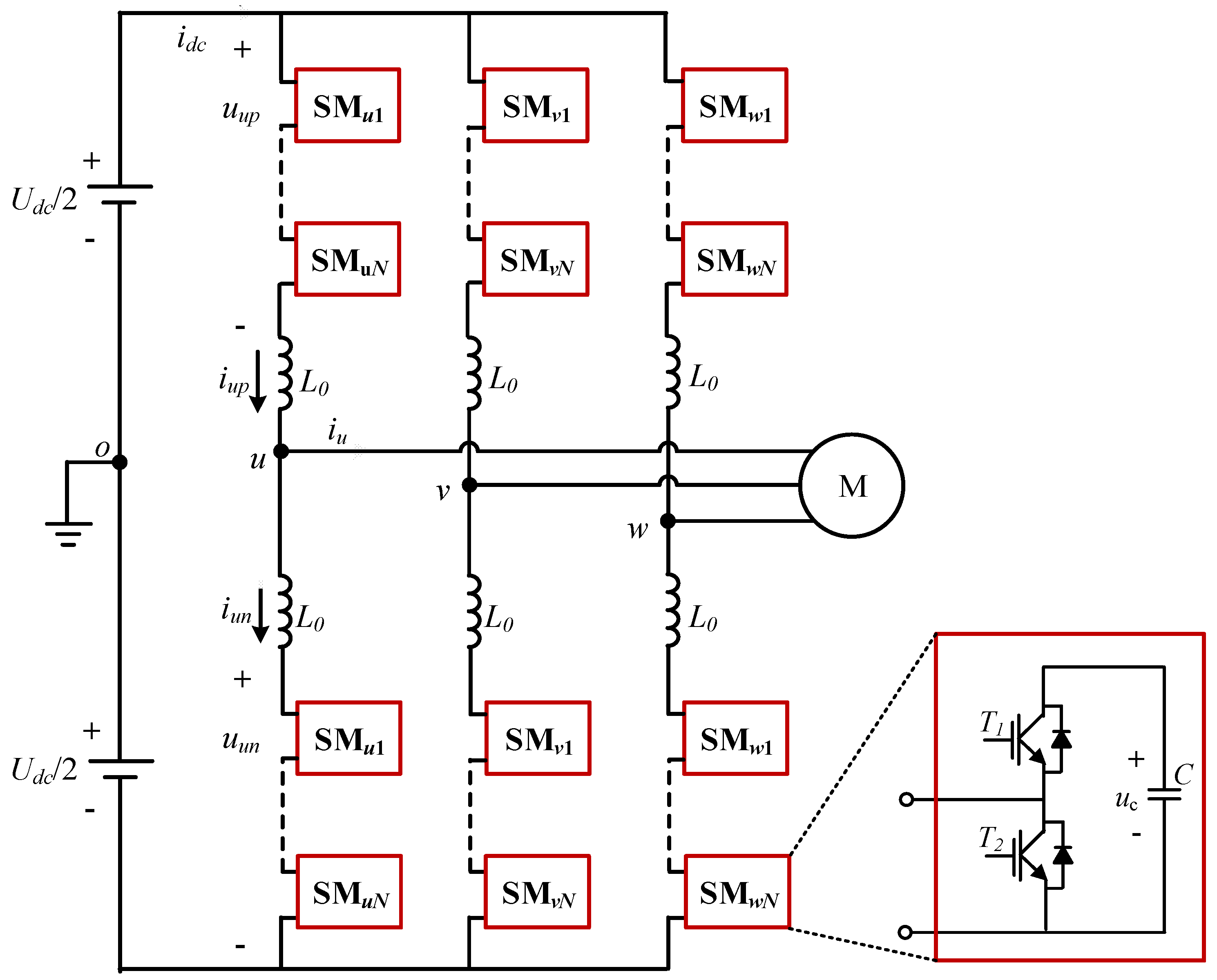
2. Proposed SMs Grouping Management and SVM Realization

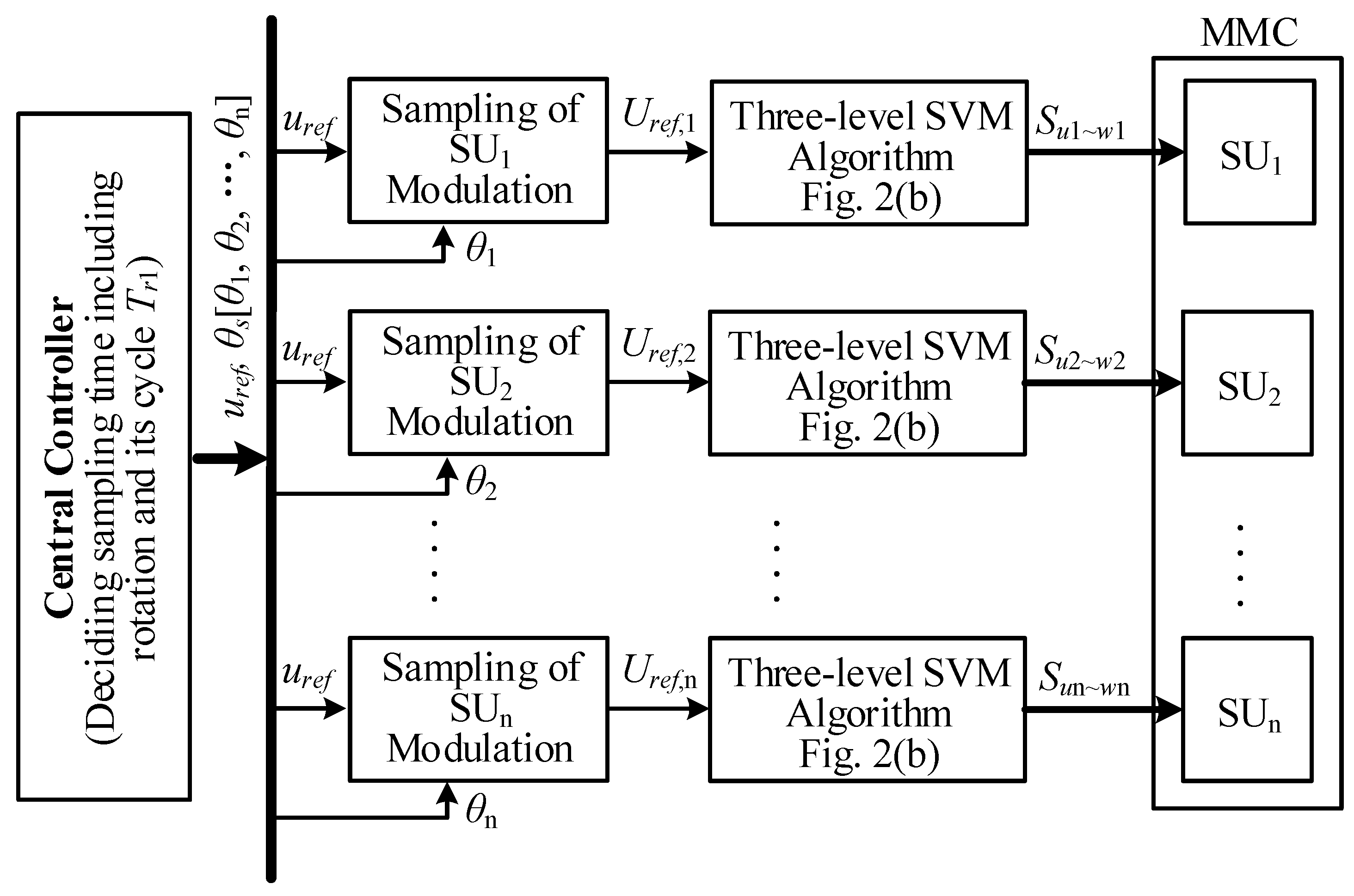
2.1. Concept of the SM Grouping Management

Since the MMC topology has a large number of switches, and hence very many switching states, it is a heavy burden to map out the complete space vector diagram of the MMC, not to mention the design of the next post-fault operation such as detection, location of fails and fault-tolerant operation, etc.
In this respect, the concept of the SMs grouping management is firstly proposed, which will facilitate the realization of SVM and implementation of the tasks related to the post-fault operation. As seen in Figure 2a, every six SMs of the same side bridge arm are grouped into a subunit (SU), in which every two SMs belong to the same phase. Evidently, each phase in a SU can output three voltage levels: 2uc, uc and 0, so it is called a three-level SU in this paper. Here, uc is the capacitor voltage and ideally equals to Udc/n. Thus, an MMC topology with n SMs per arm can be divided into n three-level SUs, half of which are on the upper arm and half on the lower arm. It is worth mentioning that the SMs in a SU are not necessarily located adjacent to or at the same position on the arms, so the SUi (i = 1,2,...,n) is conceptually “virtual”.

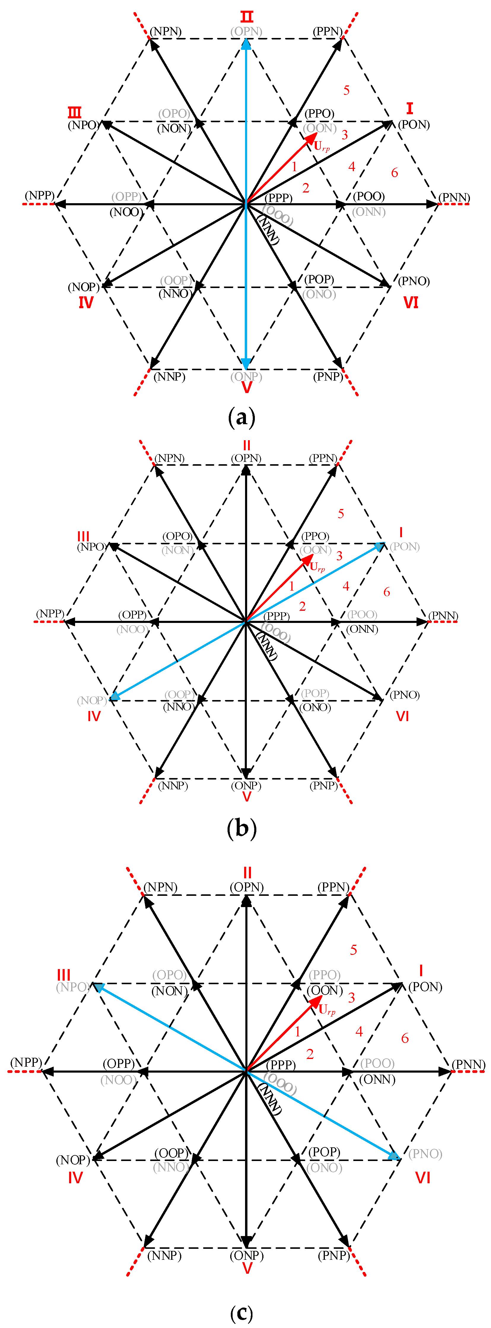
2.2. Realization of the Simplified SVM

Due to similarity of structure, it is easy to analyze that each SU can be modulated with the three-level SVM algorithm, and the corresponding space vector diagram is revealed as in Figure 2b. Thus, the determination of the switching sequences and the on-time calculation of the voltage vectors for each SU become much easier. As seen from Figure 2b, there are 19 vectors including six large vectors, six medium vectors, six small vectors, and one zero vector. The three letters in each vector bracket indicate the states of the three-phase system by corresponding to the phases u, v, w. “P” indicates that the phase in the SU outputs the highest voltage level, 2uc. “O” means the phase output in the SU is at the intermediate level, uc. When the phase voltage is 0, which is the lowest level, it is defined as the state “N”. As seen, each small vector has redundancy. For example, the vector (NON) is the redundancy of the vector (OPO). The use of redundant vectors may be an easy way to achieve fault-tolerant operation, but this is not applicable for all fault conditions. For example, the medium vectors and large vectors have no redundancy, so the fault-tolerant operation cannot be achieved by just using the redundant vectors.
On this basis, a simplified SVM implementation method is derived for the MMC and the whole schematic diagram of its implementation is illustrated in Figure 3. As seen, the SVM process for a high-level MMC can be easily completed through fulfilling multiple traditional three-level SVM algorithms. Therefore, the complicated off-line or on-line efforts/tasks about mapping switching states or sequences in the conventional multilevel SVM are not necessary any more. Besides, in order to achieve a higher equivalent output harmonic order, the sampling moments for the modulated references of the different SUs are staggered as [θ1,θ2,..., θn], as shown in Figure 3.

3. Proposed Fault-Tolerant Operation Schemes

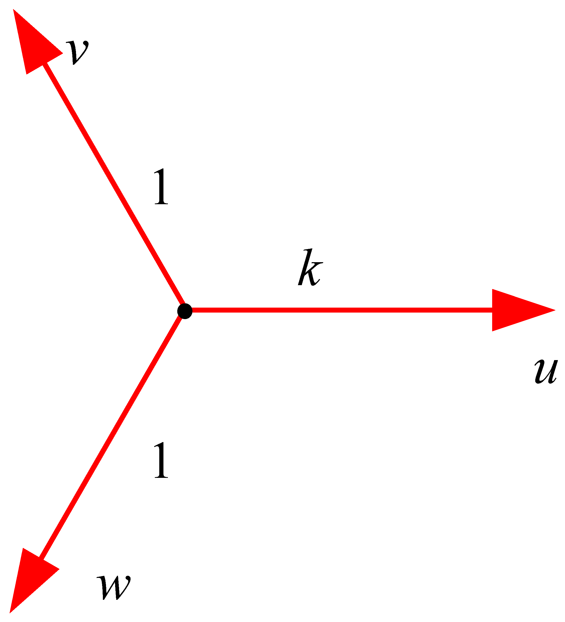
3.1. Standardization of Reference Coordinate System

When a SM fails, the usual practice is to bypass it. In the MMC, each phase has two arms and the two arm voltages synthesize the output phase voltage. In order to ensure the symmetry of the output, not only the faulty SM is bypassed, but the other arm in the same phase should also bypass the same number of SMs including the faulty and normal ones. Therefore, it permits at most half number of SMs in a phase to fail. Thus, only the rest healthy SMs can be inserted into the MMC operation, so the voltage of each SM capacitor at the steady state will be
u’c = Udc/(n − nf )
In (1), nf is the number of SMs bypassed due to failures in an arm.
It is clear u’cuc. As a result, the reference coordinate system of space vector diagram under the faulty situation is different from that under the normal situation. Therefore, the reference vector length is standardized here. Define a scalar factor of vector length k,
K = uc/(2uc) = n/[2(nnf )]
As an example, the standardized reference coordinate system of the SU with one broken SM in phase u is given in Figure 4. As seen, the unit length of the coordinate system for the normal phase is 1 while the unit length for the faulty phase is k. Thus, the space vector locations with faulty SMs can be illustrated in the same way as that in the normal condition.

3.2. Proposed Fault-Tolerant Operation Scheme

The proposed fault-tolerant scheme is based on the concept of SUs. According to the number of the faulty SMs, the following analysis will be divided into two cases: one SM failure and multiple SMs failures.
(1)
One SM failure
When a MMC has a SM failure, the defected SM may appear in phase u, phase v or phase w, and the corresponding failure is called as type u, type v or type w, respectively. The space vector diagrams for each failure type are illustrated in Figure 5. Due to a SM failure, the defected phase only has two voltage levels: u’c and 0. Following the definition of the states in Figure 3, u’c corresponds to the “P” state, and there is no “O” state due to there being no intermediate level. Therefore, the vectors related to the “O” state of phase u is missed, as the grey vectors in Figure 5. As seen, the missed vectors include six small vectors, two medium vectors and a zero vector. As analyzed before, small vectors have redundancies, so the missed six small vectors can be replaced by their redundant ones. However, there is no substitute for the missed medium vectors. Therefore, they are virtual vectors as drawn in blue arrows and will be composited by other adjacent vectors.
(2)
Multiple SMs failures
When a MMC has multiple SMs failures, the defected SMs may appear in one phase, two phases or even three phases. In these cases, this paper presents a SM exchanging strategy. This means the faulty SUs borrow a SM from other healthy SUs. In this way, the cases with multiple SM failures can be changed into multiple typical fault types, which will be divided into two cases.
One case is that the failed SMs are in the same phase in a SU. As shown in Figure 6a, both SMs in phase u are defected, as the highlighted SMs with grey color. By exchanging SMs with a healthy SU, the faulty SUf with two faulty SMs and the borrowed healthy SUh are changed into two faulty SUs both with type u.
The other case is that the failed SMs are in different phases. As shown in Figure 6b, both phase u and phase v have a faulty SM. By exchanging SMs with a healthy SU, the faulty SUf and the healthy SUh are changed into two faulty SUs, respectively, with type u and type v.
It is worth pointing out that when there are more than two SM failures in a SU, the defected SU needs to exchange SMs with more than one healthy SU. If the number of the defected SMs in a SU is m, the number of the healthy SU required for exchange is m − 1. Thus, a SU with multiple SM failures is decomposed into multiple SU with one defected SM. Therefore, the fault tolerance methods can be unified as type u, type v and type w.
From the above, with SMs grouping management, the fault-tolerant strategies can be summarized into the above three types, regardless of how many SMs of a SU fail. As a result, the fault-tolerant operation of MMC are unified.

3.3. Implementation

As analyzed above, in each of the three failure types, there are two medium vectors lost. Since medium vectors don’t have redundant vectors, it is necessary to synthesize the lost medium vectors by utilizing the remaining adjacent vectors. For example, in type u, the lost medium vectors are (OPN) and (ONP), so they are combined by the adjacent large vectors. Suppose the action times of vectors (OPN) and (ONP) in normal operation are 2tx and 2ty, respectively. According to the length of vectors in the space vector diagram, there are the following triangle synthesis rules, as shown in Figure 7.
The realization of the synthesis process can be expressed by the following equations:
2tx × (OPN) = tx × (NPN) + tx × (PPN)
2ty × (ONP) = ty × (NNP) + ty × (PNP)
Here, the calculation of vector action time in the conventional three-level SVM can be used as (5).
{ V 1 t 1 + V 2 t 2 + V 3 t 3 = V r e f T s t 1 + t 2 + t 3 = T s
V r e f is the reference vector, V 1 , V 2 and V 3 are three static vectors closest to V r e f . Ts is the carrier cycle and equals to the sampling period. According to (5), the action periods t1, t2 and t3 can be calculated. In this paper, the corresponding vectors are divided into seven stages to act in each cycle. Although t1, t2 and t3 are different in every small sector, they can be arranged as a time sequence by corresponding to the vectors. In the normal operation, the action sequence is described as
SE = [ t 1 4 , t 2 2 , t 3 2 , t 1 2 , t 3 2 , t 2 2 , t 1 4 ]
The values of t1, t2 and t3 depend on the calculation results in different sectors.
It should be noted that in order to avoid possible increasing of the harmonics and switching losses, it is necessary to reasonably arrange the action order of vectors. Therefore, two criterions should be considered: (1) center symmetry pulse sequence and (2) as few switching processes as possible. Therefore, the action sequence of the vectors may be different from that in normal conditions.
Here, type u in Figure 5a is taken as an example, all possible sequences are derived as (7). Since phase u has a faulty SM, the medium vectors in sectors II and V are missed. As a result, the sequence arrangement in these two sectors are more complex than those in other sectors, so the sector II-5 is taken as an example to show the derivation of the sequences. Table 1 shows the action sequences of vectors under the normal conditions and type u fault, respectively.
{ SE 1 = [ t 3 2 , t 1 2 , t 2 4 , t 2 2 , t 2 4 , t 1 2 , t 3 2 ] SE 2 = [ t 1 2 , t 3 4 , t 3 4 , t 2 , t 3 4 , t 3 4 , t 1 2 ] SE 3 = [ t 3 2 , t 2 4 , t 2 4 , t 1 , t 2 4 , t 2 4 , t 3 2 ] SE 4 = [ t 1 2 , t 2 2 + t 3 4 , t 3 8 , t 3 4 , t 3 8 , t 2 2 + t 3 4 , t 1 2 ] SE 5 = [ t 2 4 , t 3 2 + t 2 4 , t 1 4 , t 1 2 , t 1 4 , t 3 2 + t 2 4 , t 2 4 ] SE 6 = [ t 1 2 , t 2 2 , t 3 4 , t 3 2 , t 3 4 , t 2 2 , t 1 2 ] SE 7 = [ t 3 2 , t 1 2 , t 2 4 , t 2 2 , t 2 4 , t 1 2 , t 3 2 ] SE 8 = [ t 2 2 , t 3 2 , t 1 4 , t 1 2 , t 1 4 , t 3 2 , t 2 2 ]
As seen, under normal conditions, the action sequence is just as SE in (6). The action periods for (NON), (NPN), (OPN) and (OPO) are t1/2, t2, t3 and t1/2, respectively. For a type u fault, (OPO) is replaced by (NON), so the total action time of (NON) is increased by t1/2 which is originally the action time for (OPO). Since (OPN) is synthesized from (NPN) and (PPN) as given in Figure 7, according to equation (3), the increased action time of (NPN) and action time of (PPN) are t3/2 which is half of the action time for (OPN). Finally, the action times for (NON), (NPN) and (PPN) are t1, t2+t3/2 and t3/2, respectively. To achieve the above two criterions, the action sequence of vectors is arranged as the second line in Table 1. In this way, the action sequence is SE4 given in (7). For the sake of saving space, the derivation process of action sequences in other sectors are not given here. Table 2 shows the vector sequences in all small sectors and the corresponding time sequences.
Due to three-phase symmetry, for the other two failure types: type v and type w, the process to calculate the action time and arrange the sequence is similar to that with type u. Due to space limitations, exact results are not given here.
The flow chart of the presented fault tolerant strategy is shown in Figure 8. It is worth mentioning that this paper focuses on the post-fault operation of MMC, so there is no discussion about the fault detected process here.

3.4. Capacitor Voltage Balance

Regardless of whether it is in the normal operation or in fault-tolerant operations, the SM capacitor voltage balance is a problem that must be considered. According to the operation principle, the arm current is positive, the accessed SMs are charged, and when the arm current is negative, accessed SMs are discharged. Therefore, the capacitor voltage sorting strategy is merged into the proposed strategy to keep capacitor voltage balance in this paper, as the red block shown in Figure 8.
According to the sorting results of the SM capacitor voltages and the direction of the arm currents, the switching signals calculated by the three-level SVM algorithm are distributed to the selected SMs. In this understanding, it is easy to know that after considering the capacitor voltage balance, the switching signals are directly assigned to SMs, not SUs. Therefore, “SU” is just a virtual concept derived from the description of the modulation process. This also further illustrates the statement in Section 2, that the SMs in a SU are not necessarily located adjacent to or at the same position on the arms.

4. Simulation Results

The performance of the proposed FT strategy is first evaluated on a MatLab/SimuLink three-phase MMC model. The parameters are shown in Table 3.
Take phase u as an example, the simulated waveforms of phase voltages, line voltages and load currents in the normal operation are displayed in Figure 9. As seen, the MMC can work well; especially the phase voltage has 11 levels, while the line voltage waveform is also very symmetrical. Figure 10 shows the simulated results with the type u failure where only phase u has a defected SM. Obviously, even if one SM in the MMC fails, the MMC can still keep operating. However, since the defected SM and another healthy SM in the other arm are bypassed, the faulty phase only has eight SMs inserted every moment. Therefore, the phase voltage with the faulty SM only has nine levels while the waveform of the line voltage is not as symmetrical as in the normal operation. Further, the calculated THD values of the line voltages are also concluded in Table 4. As seen, the fundamental amplitude values of the line voltages are only slightly changed, and the THD results are just slightly increased.

5. Experimental Results

A three-phase MMC lab prototype with four SMs per arm is also built to verify the propositions. The control system is based on a digital signal processing chip (DSP) and three field-programmable gate array (FPGA) and the tested parameters are given in Table 5.
Figure 11 shows the tested waveforms of phase voltage, the line voltage and the output current of phase u under normal conditions. As seen, under normal conditions, the MMC can work well with the phase voltage and the line voltage being very neat and symmetrical multilevel waveforms shown in Figure 11a,b. From Figure 11d, the SM capacitor voltages can be kept at 75 V which is the balanced voltage value. Also in Figure 11d, from the bottom curve which is the zoomed-in capacitor voltage, the voltage ripple is less than 1 V.
Figure 12 shows the tested waveforms of phase voltage, the line voltage and the output current of phase u with type u failure. During testing, as an example of type u fault, the second SM in the upper arm of phase u is turned off to imitate an open-circuit fault, and the tested waveforms with the presented fault-tolerant method are given in Figure 12. Since phase u has a broken SM, it has three SMs inserted in every switching period, while phase v and phase w have four SMs inserted, respectively. Therefore, the waveform of uvw is similar to that under the normal condition, while the waveforms related to phase A such as uuv and uwu are changed. From Figure 12a,b, the level number of the line voltages related to the broken phase is reduced during post-fault operations, so the line voltage waveform is not as symmetrical as in the normal operation. However, the peak values of the line voltages are not reduced due to the use of the presented strategy. As seen in Figure 12d, the balanced capacitor voltages of the phase u are increased to be 100 V. This is because the phase u only has three SMs inserted in every switching period while the healthy phases v and w, respectively, have four SMs inserted in every switching period.
Figure 13 shows some tested waveforms of the transient process from normal operation to type u failure. As seen in Figure 13a–c, the transient process is gentle. In Figure 13d, after the failure happens, the SM capacitor voltages in failure phase increases from 75 V to 100 V due to less SMs inserted.

6. Conclusions

By introducing the concept of the SMs grouping management, the SVM implementation for the MMC is simplified and can be completed only by carrying out multiple three-level SVM algorithms. On this basis, the post-fault operation of the MMC is investigated and a unified fault-tolerant operation strategy is proposed. In terms of a subunit (SU), its failure can be categorized into three basic types with each type having one SM failure in a SU, and the failures with more defected SMs can be decomposed into multiple basic types by exchanging SMs with other healthy SUs. Further, the corresponding fault-tolerant strategies are developed and unified by only proposing the fault-tolerant strategies for three basic failure types. Additionally, the sorting capacitor voltage control is combined into the proposed methods to solve the SM capacitor voltage balance problems. Simulation and experimental results verify the propositions by providing some key waveforms in normal condition and with SM failures.

Author Contributions

Funding acquisition, Z.B.; Investigation, Z.B. and Y.L.; Software, Y.L.; Supervision, Z.B. All authors have read and agreed to the published version of the manuscript.

Funding

This research was funded by [National Natural Science Foundation of China] grant number [51877194].

Institutional Review Board Statement

Not applicable.

Informed Consent Statement

Not applicable.

Conflicts of Interest

The authors declare no conflict of interest.

References

  1. Du, S.; Wu, B.; Tian, K.; Zargari, N.R.; Cheng, Z. An Active Cross-Connected Modular Multilevel Converter (AC-MMC) for a Medium-Voltage Motor Drive. IEEE Trans. Ind. Electron. 2016, 63, 4707–4717. [Google Scholar] [CrossRef]
  2. Hagiwara, M.; Nishimura, K.; Akagi, H. A Medium-Voltage Motor Drive with a Modular Multilevel PWM Inverter. IEEE Trans. Power Electron. 2010, 25, 1786–1799. [Google Scholar] [CrossRef]
  3. Tang, G.; Xu, Z.; Zhou, Y. Impacts of three MMC-HVDC configurations on AC system stability under DC line faults. In Proceedings of the 2015 IEEE Power & Energy Society General Meeting, Denver, CO, USA, 26–30 July 2015; p. 1. [Google Scholar]
  4. Lezana, P.; Pou, J.; Meynard, T.A.; J Rodriguez, S. Ceballos and F. Richardeau, Survey on Fault Operation on Multilevel Inverters. IEEE Trans. Ind. Electron. 2010, 57, 2207–2218. [Google Scholar] [CrossRef] [Green Version]
  5. Abdelsalam, M.; Tennakoon, S.; Griffiths, A.L.; Marei, M. Investigation of sub-module fault types of modular multi-level converters in HVDC networks. In Proceedings of the 2015 50th International Universities Power Engineering Conference (UPEC), Stroke-on-Trent, UK, 1–4 September 2015; pp. 1–6. [Google Scholar]
  6. Rodriguez, J.; Hammond, P.W.; Pontt, J.; Musalem, R.; Lezana, P.; Escobar, M.J. Operation of a medium-voltage drive under faulty conditions. IEEE Trans. Ind. Electron. 2005, 52, 1080–1085. [Google Scholar] [CrossRef]
  7. Yang, S.; Bryant, A.; Mawby, P.; Xiang, D.; Ran, L.; Tavner, P. An Industry-Based Survey of Reliability in Power Electronic Converters. IEEE Trans. Ind. Appl. 2011, 47, 1441–1451. [Google Scholar] [CrossRef]
  8. Richardeau, F.; Pham, T.T.L. Reliability Calculation of Multilevel Converters: Theory and Applications. IEEE Trans. Ind. Electron. 2013, 60, 4225–4233. [Google Scholar] [CrossRef]
  9. Li, B.; Zhang, Y.; Yang, R.; Xu, R.; Xu, D.; Wang, W. Seamless Transition Control for Modular Multilevel Converters When Inserting a Cold-Reserve Redundant Submodule. IEEE Trans. Power Electron. 2015, 30, 4052–4057. [Google Scholar] [CrossRef]
  10. Li, K.; Yuan, L.; Zhao, Z.; Lu, S.; Zhang, Y. Fault-Tolerant Control of MMC With Hot Reserved Submodules Based on Carrier Phase Shift Modulation. IEEE Trans. Power Electron. 2017, 32, 6778–6791. [Google Scholar] [CrossRef]
  11. Wang, J.; Tang, Y. A Fault-Tolerant Operation Method for Medium Voltage Modular Multilevel Converters with Phase-Shifted Carrier Modulation. IEEE Trans. Power Electron. 2019, 34, 9459–9470. [Google Scholar] [CrossRef]
  12. Hu, P.; Jiang, D.; Zhou, Y.; Liang, Y.; Guo, J.; Lin, Z. Energy-balancing Control Strategy for Modular Multilevel Converters Under Submodule Fault Conditions. IEEE Trans. Power Electron. 2014, 29, 5021–5030. [Google Scholar] [CrossRef]
  13. Ghazanfari, A.; Mohamed, Y.A.I. A Resilient Framework for Fault-Tolerant Operation of Modular Multilevel Converters. IEEE Trans. Ind. Electron. 2016, 63, 2669–2678. [Google Scholar] [CrossRef]
  14. Deng, F.; Tian, Y.; Zhu, R.; Chen, Z. Fault-Tolerant Approach for Modular Multilevel Converters under Submodule Faults. IEEE Trans. Ind. Electron. 2016, 63, 7253–7263. [Google Scholar] [CrossRef]
  15. Wang, J.; Ma, H.; Bai, Z. A Submodule Fault Ride-Through Strategy for Modular Multilevel Converters with Nearest Level Modulation. IEEE Trans. Power Electron. 2018, 33, 1597–1608. [Google Scholar] [CrossRef]
  16. Yang, S.; Tang, Y.; Wang, P. Seamless Fault-Tolerant Operation of a Modular Multilevel Converter with Switch Open-Circuit Fault Diagnosis in a Distributed Control Architecture. IEEE Trans. Power Electron. 2018, 33, 7058–7070. [Google Scholar] [CrossRef]
  17. Haghnazari, S.; Vahedi, H.; Zolghadri, M.R. Fault tolerant operation strategy design for modular multilevel converters. In Proceedings of the IECON 2016—42nd Annual Conference of the IEEE Industrial Electronics Society, Florence, Italy, 24–27 October 2016; pp. 2172–2176. [Google Scholar]
  18. Xu, K.; Xie, S.; Wang, X.; Zhang, B.; Bian, S. Model Predictive-based Fault-tolerant Control for Modular Multilevel Converters without Redundant Submodules. In Proceedings of the 2018 IEEE International Power Electronics and Application Conference and Exposition (PEAC), Shenzhen, China, 4–7 November 2018; pp. 1–5. [Google Scholar]
  19. Yang, Q.; Qin, J.; Saeedifard, M. A Postfault Strategy to Control the Modular Multilevel Converter under Submodule Failure. IEEE Trans. Power Deliv. 2016, 31, 2453–2463. [Google Scholar] [CrossRef]
  20. Dong, Y.; Yang, H.; Li, W.; He, X. Neutral-Point-Shift-Based Active Thermal Control for a Modular Multilevel Converter under a Single-Phase-to-Ground Fault. IEEE Trans. Ind. Electron. 2019, 66, 2474–2484. [Google Scholar] [CrossRef]
  21. Farzamkia, S.; Iman-Eini, H.; Noushak, M.; Hadizadeh, A. Improved Fault-Tolerant Method for Modular Multilevel Converters by Combined DC and Neutral-Shift Strategy. IEEE Trans. Ind. Electron. 2019, 66, 2454–2462. [Google Scholar] [CrossRef]
  22. Kim, S.; Lee, K.; Lee, J. Fault-tolerant control scheme for modular multilevel converter based on sorting algorithm without reserved Submodules. In Proceedings of the 2018 IEEE Applied Power Electronics Conference and Exposition (APEC), San Antonio, TX, USA, 4–8 March 2018; pp. 223–227. [Google Scholar]
  23. Li, B.; Shi, S.; Wang, B.; Wang, G.; Wang, W.; Xu, D. Fault diagnosis and tolerant control of Single IGBT open-circuit failure in Modular multilevel converters. IEEE Trans. Power Electron. 2016, 31, 3165–3176. [Google Scholar] [CrossRef]
  24. Farzamkia, S.; Iman-Eini, H.; Khoshkbar-Sadigh, A.; Noushak, M. A software-based fault-tolerant strategy for modular multilevel converter using DC bus voltage control. IEEE J. Emerg. Sel. Top. Power Electron. 2020, 9, 3436–3445. [Google Scholar] [CrossRef]
  25. Li, B.; Xu, Z.; Ding, J.; Xu, D. Fault-tolerant control of medium-voltage modular multilevel converters with minimum performance degradation under submodule failures. IEEE Access 2018, 6, 11772–11781. [Google Scholar] [CrossRef]
  26. Abdelsalam, M.; Marei, M.I.; Tennakoon, S.B. An integrated control strategy with fault detection and tolerant control capability based on capacitor voltage estimation for modular multilevel converters. IEEE Trans. Ind. Appl. 2017, 53, 2840–2851. [Google Scholar] [CrossRef]
  27. Deng, Y.; Wang, Y.; Teo, K.H.; Saeedifard, M.; Harley, R.G. Optimized Control of the Modular Multilevel Converter Based on Space Vector Modulation. IEEE Trans. Power Electron. 2018, 33, 5697–5711. [Google Scholar] [CrossRef]
  28. Aleenejad, M.; Mahmoudi, H.; Jafarishiadeh, S.; Ahmadi, R. Fault-Tolerant Space Vector Modulation for Modular Multilevel Converters with Bypassed Faulty Submodules. IEEE Trans. Ind. Electron. 2019, 66, 2463–2473. [Google Scholar] [CrossRef]
  29. Bai, Z.; Chen, H.; Ma, H. Implementation of Space Vector Modulation (SVM) for Modular Multilevel Converter Based on Submodule Regroup. In Proceedings of the 2018 IEEE International Power Electronics and Application Conference and Exposition (PEAC), Shenzhen, China, 4–7 November 2018; pp. 1–6. [Google Scholar]
Figure 1. Circuit diagram of one phase of MMC.
Energies 15 05694 g001
Figure 2. SMs grouping management to form three-level SUs (a) three-level SU and its (b) space vectors diagram.
Energies 15 05694 g002
Figure 3. Schematic diagram of the presented SVM for MMC.
Energies 15 05694 g003
Figure 4. Standardized reference coordinate system with phase u broken.
Energies 15 05694 g004
Figure 5. Space vector diagram of typical fault types (a) type u (b) type v and (c) type w.
Energies 15 05694 g005
Figure 6. Decomposition of multiple SM faults in (a) one defected phase (b) two defected phases.
Energies 15 05694 g006
Figure 7. Vector synthesis diagram.
Energies 15 05694 g007
Figure 8. Flow chart of the presented FT strategy.
Energies 15 05694 g008
Figure 9. Simulated waveforms (normal operation).
Energies 15 05694 g009
Figure 10. Simulated waveforms (type u fault).
Energies 15 05694 g010
Figure 11. Experimental results under normal conditions (a) phase u voltage (b) line voltage uuv (c) current of phase u (d) some SM capacitor voltages of phase u and one zoomed-in curve.
Energies 15 05694 g011aEnergies 15 05694 g011b
Figure 12. Experimental results with type u fault (a) phase u voltage (b) line voltage uuv (c) current of phase u (d) some SM capacitor voltages of phase u and one zoomed-in curve.
Energies 15 05694 g012aEnergies 15 05694 g012b
Figure 13. Experimental results of transient process from normal operation to type u failure (a) phase u voltage (b) line voltage uuv (c) current of phase u (d) some SM capacitor voltages of phase u and one zoomed-in curve where the voltage ripple is less than 1 V.
Energies 15 05694 g013aEnergies 15 05694 g013b
Table 1. Action sequence of vectors in sector II-5.
ConditionsAction Sequence of Vectors
NormalNONNPNOPNOPOOPNNPNNON
Type u faultNONNPNPPNPPNPPNNPNNON
Table 2. The sequence and action time of vectors.
SectorsTimeSwitching Sequence
I-1SE7POO-PPO-PPP-PPP-PPP-PPO-POO
I-2SE6POO-PPO-PPP-PPP-PPP-PPO-POO
I-3SE8PON-POO-PPO-PPO-PPO-POO-PON
I-4SE7PON-POO-PPO-PPO-PPO-POO-PON
I-5SE8PON-PPN-PPO-PPO-PPO-PPN-PON
I-6SE8PNN-PON-POO-POO-POO-PON-PNN
II-1SE1NNN-NON-PPO-PPO-PPO-NON-NNN
II-2SE1NON-PPO-PPP-PPP-PPP-PPO-NON
II-3SE2NON-NPN-PPN-PPO-PPN-NPN-NON
II-4SE3NON-NPN-PPN-PPO-PPN-NPN-NON
II-5SE4NON-NPN-PPN-PPN-PPN-NPN-NON
II-6SE5NPN-PPN-PPO-PPO-PPO-PPN-NPN
III-1SE8NNN-NON-NOO-NOO-NOO-NON-NNN
III-2SE7NNN-NON-NOO-NOO-NOO-NON-NNN
III-3SE7NON-NOO-NPO-NPO-NPO-NOO-NON
III-4SE6NON-NOO-NPO-NPO-NPO-NOO-NON
III-5SE6NOO-NPO-NPP-NPP-NPP-NPO-NOO
III-6SE6NON-NPN-NPO-NPO-NPO-NPN-NON
IV-1SE7NNN-NNO-NOO-NOO-NOO-NNO-NNN
IV-2SE8NNN-NNO-NOO-NOO-NOO-NNO-NNN
IV-3SE6NNO-NOO-NOP-NOP-NOP-NOO-NNO
IV-4SE7NNO-NOO-NOP-NOP-NOP-NOO-NNO
IV-5SE6NNO-NNP-NOP-NOP-NOP-NNP-NNO
IV-6SE6NOO-NOP-NPP-NPP-NPP-NOP-NOO
V-1SE1NNO-POP-PPP-PPP-PPP-POP-NNO
V-2SE1NNN-NNO-POP-POP-POP-NNO-NNN
V-3SE3NNO-NNP-PNP-POP-PNP-NNP-NNO
V-4SE2NNO-NNP-PNP-POP-PNP-NNP-NNO
V-5SE5NNP-PNP-POP-POP-POP-PNP-NNP
V-6SE4NNO-NNP-PNP-PNP-PNP-NNP-NNO
VI-1SE6POO-POP-PPP-PPP-PPP-POP-POO
VI-2SE7POO-POP-PPP-PPP-PPP-POP-POO
VI-3SE7PNO-POO-POP-POP-POP-POO-PNO
VI-4SE8PNO-POO-POP-POP-POP-POO-PNO
VI-5SE8PNN-PNO-POO-POO-POO-PNO-PNN
VI-6SE8PNO-PNP-POP-POP-POP-PNP-PNO
Table 3. Simulation parameters.
ParametersIndexesValues
No. of SMs per armN10
DC-link voltageUdc800 V
Switching frequencyfs1 kHz
Modulation indexm0.97
Fundamental frequencyfo50 Hz
Arm inductanceLs3 mH
LoadLload3 mH
Rload10 Ω
Table 4. The values of line voltages.
Conditionsuuvuvwuwu
THD (%)Amplitude (V)THD (%)Amplitude (V)THD (%)Amplitude (V)
Normal7.98779.97.957807.98780
Type u9.52776.78.27779.89.52777.3
Table 5. Experimental parameters.
ParametersIndexesValues
No. of SMs per armN4
dc-link voltageUdc300 V
SM capacitanceC2350 μF
Switching frequencyfs1 kHz
Modulation indexm0.97
Fundamental frequencyfo50 Hz
Arm inductanceLs7.7 mH
LoadLload1 mH
Rload50 Ω
Publisher’s Note: MDPI stays neutral with regard to jurisdictional claims in published maps and institutional affiliations.

