Article

Numerical Investigation of Heat Transfer Performance and Structural Optimization of Fan-Shaped Finned Tube Heat Exchanger

School of Urban Construction, Wuhan University of Science and Technology, Wuhan 430081, China
*
Author to whom correspondence should be addressed.
Energies 2022, 15(15), 5682; https://doi.org/10.3390/en15155682
Submission received: 13 July 2022 / Revised: 1 August 2022 / Accepted: 1 August 2022 / Published: 5 August 2022
(This article belongs to the Special Issue Application of Renewable Energy in Buildings)

Abstract

:
Latent heat storage technology is widely used in solar power generation. Aiming to enhance the energy utilization rate to a greater extent, an innovative fan-shaped structure has been proposed to construct the metal fins of the shell-and-tube thermal storage device. The enthalpy method is used to simulate the heat storage process and focuses on the influence of inlet conditions on heat transfer. The influence of the fin structure on the melting properties of phase change material has been studied. The results show that increasing inlet temperature and inlet flow rate is a convenient and effective way to improve energy efficiency. As the inlet temperature is increased from 343 K to 358 K, the total heat storage and energy efficiency are improved by 13.4% and 10.2%, respectively, and the melting time is reduced by 36.2%. As the flow rate is increased from 3 L/min to 9 L/min, the complete melting time is reduced by 33.4%. Energy efficiency peaks at a flow rate of 5 L/min. Reasonable optimization of the fin structure can enhance the natural convection circulation during the melting process and further improve the energy efficiency. The research results can guide the design and structural optimization of the finned tube heat storage device.

1. Introduction

Global energy consumption is increasing rapidly, and the problem of environmental pollution is becoming more and more serious [1]. Solar energy is abundant, clean, and harmless and has a wide range of applications. However, due to the intermittent and fluctuating nature of solar energy, thermal energy storage (TES) technology is required to solve the dilemma between energy supply and demand [2,3]. PCM has a wide range of applications in TES, including building heating [4], electronic device cooling [5], solar energy systems [6], air conditioning [7], waste heat recovery [8], hybrid cooling clothing [9], and subsea pipeline insulation [10]. Therefore, improving the thermal performance of TES systems has become a current research focus.
Paraffin is a phase change material (PCM) commonly used in latent heat storage (LHS) systems, with the advantages of stable thermophysical properties, safety, low price, and no corrosion [11]. However, its main limitation is its low thermal conductivity, resulting in low energy conversion efficiency, which greatly limits the thermal performance of LHS systems. In order to enhance the thermal efficiency of LHS, scholars have conducted extensive research to improve the thermal conductivity of PCM [12] by adding nanoparticles [13], metal foams [14], or preparing composite PCM [15]. After extensive experiments and simulation verifications [16,17], Pássaro et al. [18] discovered that the combination of fins and nanoparticles can significantly improve the discharge process, but as the number of fins increases, the role of nanoparticles becomes secondary. Alizadeh et al. [19] found that adding innovative fins is a more efficient method than making nano-enhanced PCM, with a 30% reduction in full solidification time, while nano-enhanced PCMs can only reduce full solidification time by 14.5%. Although adding fins will reduce the capacity of the PCM in the heat storage unit [20], it can greatly shorten the melting time of the PCM, which can significantly and efficiently improve the overall heat transfer performance of the LHS system [21,22].
It can be found that the addition of metal fins can greatly improve the thermal conductivity, and under certain conditions may cause vortex formation and natural/force convection enhancement, improving the heat transfer rate. Mekrisuh et al. [23] proposed that adding fins to the TES system can markedly improve thermal conductivity. Tay et al. [24] numerically investigated the effect of adding pins and fins on heat transfer enhancement and found that thermally conductive fins could further enhance heat transfer rate. Yang et al. [25] numerically investigated the influence of annular fins on the melting characteristics of PCM in a shell-and-tube LHS system and believed that adding annular fins could shorten the complete melting time of PCM by 65%. Guo et al. [26] proposed a novel angular fin design based on annular fins and studied the effect of annular fin bending angle on the melting rate of PCM. To further enhance the thermal storage efficiency of LHS system, scholars have conducted more in-depth research on the effect of different fin parameters on the melting and solidification process of PCMs in LHS units, including fin number [27], fin height [28], fin angle [29], fin arrangement [30], and fin shape [31] among other factors. Akhilesh et al. [32] studied the influence of fin number on the thermal storage performance and pointed out that with the increase of the number of fins, the melting rate gradually increased. However, when the fin number exceeded the critical value, the enhanced heat transfer effect was very weak. Wang et al. [33] studied in detail the effects of fin geometry and outer tube thermal conductivity on the PCM melting process. It was pointed out that the smaller fin ratio could shorten the melting time, and the thermal conductivity of the outer tube had a great influence on the melting process. Shahsavar et al. [34] studied the effect of non-uniform fin arrangement on the melting and solidification process of PCM. By optimizing the arrangement spacing between the fins, the melting and solidification times were shortened by 41.4% and 9.7%, respectively. Yagci et al. [35] investigated the effect of edge length ratio of fins in shell and tube heat exchangers during the melting and solidification of PCMs. The results showed that reducing the fin edge length ratio could improve the weak natural convection motion in the lower part, thereby increasing the melting rate. On the contrary, its effect on solidification time was not significant.
Some researchers have also found that the novel fin structures can save a lot of heat storage time and enhance the heat storage efficiency compared with the traditional fin structures, such as triangle [36], tree shape [37], snowflake shape [38], V shape [39], topology [40], and so on. Mudhafar et al. [41] innovatively proposed a T-shaped fin. In the case of equal fin volume, the melting time of PCM using T-shaped fins was shortened by 33% compared with the use of longitudinal fins. In order to improve the phase transformation efficiency, Liu et al. [42] proposed a trapezoidal fin to accelerate the melting process. The results showed that trapezoidal fins could optimize the melt channel of the PCM better than straight fins. Compared with straight fins, the total melting time was saved by up to 52.2%. Ma et al. [43] proposed a novel circular stacked longitudinal fin and performed a simulation analysis of the exothermic performance and (exergy) efficiency of the LHS device. The study found that the circular reinforced fins with decreasing distribution had better heat transfer performance, and the complete solidification time of the PCM was reduced by 38.72%. Mao et al. [44] innovatively proposed a fan-shaped fin on the basis of the shell-and-tube heat storage unit. The influence of factors, such as height, number, and angle of fins on the heat storage rate, was studied and the optimal combination scheme of fan-shaped fins was obtained.
As mentioned above, adding fins helps to promote the melting of the PCM around the fins, which plays a vital role in improving the thermal efficiency of the LHS system. However, it is worth noting that the heat transfer of the PCM far from the fins has not been significantly enhanced, resulting in the positive effect of the fins to enhance heat transfer not being fully exerted. In order to improve the overall melting degree of the PCM and reduce the uneven temperature distribution, a 3D numerical model of the fan-shaped finned tube was established. The role of natural convection in the melting process was explored using different inlet temperatures and inlet flow rates. Finally, based on the fan-shaped fin structure, a variety of different fin structures were derived and analyzed. The conclusions of this paper have a certain reference value for the structural optimization and performance improvement of LHS units.

2. Physical Models and Numerical Simulations

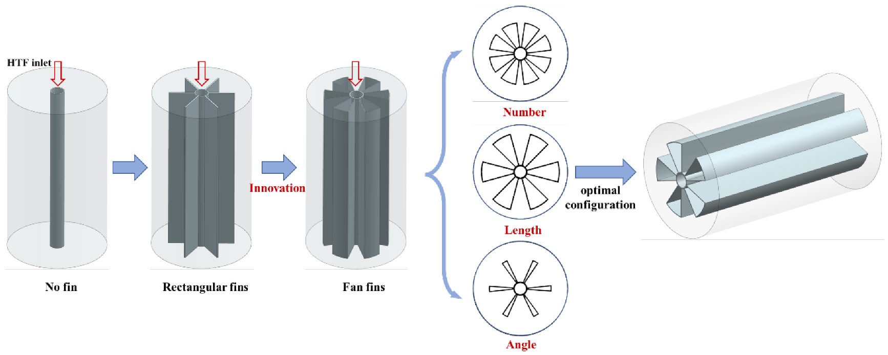
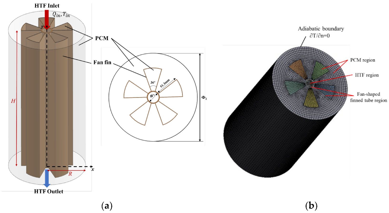
2.1. Physical Models and Computational Domains

Figure 1 describes the evolution history of the fan-shaped finned tube in detail. In a previous study [44], the effect of the number, height and angle of fins on heat transfer has been evaluated and studied, and an optimal combination of 6 fins, an angle of 30° and a height of 51.3 mm has been obtained. In order to experimentally study and verify the heat transfer performance of the fan-shaped finned tube in the subsequent research, considering that the processing and manufacturing of the fin shape is difficult, but at the same time to guarantee efficient heat transfer performance, five fan-shaped fins with an angle of 36° and a height of 51.3 mm were ultimately selected for this study. Figure 2a depicts the model diagram of the LHS unit with fan-shaped fins. The device consists of two cylinders with a height of 350 mm: the outer shell is made of acrylic, with a diameter of 200 mm, and the heat exchange tube is made of copper with an inner diameter of 25 mm and a thickness of 2 mm. Five longitudinal fan-shaped fins are evenly distributed on the surface of the copper tube. The height of the fins is 350 mm, the length is 51.3 mm, the thickness is 1 mm, and the adjacent angle is 36°. Water as heat transfer fluid (HTF) flows through the inner cooper tube at a temperature of 353 K and a flow rate of 5 L/min. The hot water exchanges heat with the paraffin in the annular cavity through copper tubes and fins. The physical parameters of paraffin wax and cooper are shown in Table 1. As can be seen from Figure 2b, the 3D model is divided into three computational domains: HTF region, PCM region, and fan-shaped finned tubes. The shell is defined as an adiabatic boundary, that is, the heat dissipation of the LHS unit to the outside world is ignored.

2.2. Mathematical Model and Governing Equations

To simplify the complexity of numerical calculations, the following assumptions are made:
(1)
The flow of PCMs is considered to be laminar, three-dimensional, and incompressible.
(2)
The viscous dissipation and volume change during phase transition are ignored.
(3)
The Boussinesq approximation is used to only consider the PCM density change caused by the temperature change.
(4)
The thermophysical properties of the PCM are constant and satisfy the isotropy.
(5)
The axial and radial temperature changes of the heat exchange tubes are ignored.
Based on the above assumptions, the governing equations are expressed as follows [26,45]:
Continuity:
· u   = 0
Momentum:
ρ f u t + ρ f ( u · ) u = P + μ f 2 u + ρ f g β   ( T f T m ) + ( 1 λ ) 2 ( λ 3 + 0.001 ) u A m u s h
Energy:
ρ f c p , f T f t + ρ f c p , f u · T f = · ( k f T f ) ρ f L f λ t
Among them, Amush is a mushy zone constant, typically between 104 and 107. It is considered as 106 in the current study.
The established mathematical model is solved by the enthalpy-porosity method [46]. The melting fraction λ represents the volume fraction of the liquid phase PCM in the melting process, and it can be expressed as:
λ = {         0                                   T < T s o l i d           T T s o l i d T l i q u i d T s o l i d           T s o l i d < T < T l i q u i d             1                                 T > T l i q u i d                      
where λ = 1 and λ = 0 for the liquid and solid PCM, Tliquid defines PCMs liquidus temperature, Tsolid defines PCMs solidus temperature.

2.3. Initial and Boundary Conditions

Initial conditions:
T | t = 0 = T 0 = 303   K
Boundary conditions:
Q i n = 5   L · m i n 1 , T = T i n = 353   K
k T | Ω n = 0
Among them, T0 represents the ambient temperature, and the initial temperature of all computational domains is 303 K. Ω represents the outer surface of the device housing, n represents the normal vector, and Qin and Tin represent the inlet volume flow and inlet temperature, respectively.
Coupling boundaries are formed between the fins and the PCM, as well as the HTF and the inner wall of copper tube:
T f i n = T P C M ,   k P C M T P C M n = k f i n T f i n n
T H T F = T t u b e ,   k H T F T H T F n = k t u b e T t u b e n

2.4. Characteristic Parameters and Evaluation Indicators

Heat storage is an important index to evaluate the performance of LHS device. Based on the melting characteristics of PCM, the total amount of heat storage can be calculated by Equation (10):
Q P C M = m P C M [ c p , s ( T m T i n i ) + λ L + c p , l ( T P C M T m ) ]
Effective heat storage refers to the heat transferred from HTF to PCM, which can be calculated by Equation (11):
Q H T F = 0 t m f ˙ c p , f [ T i n ( t ) T o u t ( t ) ] d t
where Tin (t) and Tout (t) represent the inlet and outlet temperatures of the fluid, m f ˙ represents the mass flow rate, c p , f is the specific heat capacity of water.
Heat flux refers to the amount of heat transferred per unit area per unit time and can be calculated by Equation (12):
q = 0 t m f ˙ c p , f [ T i n ( t ) T o u t ( t ) ] d t t m ( A t u b e + A f i n )
The energy efficiency is defined as the ratio of the heat stored by PCM to heat supplied by HTF, which reflects the heat utilization efficiency of LHS system.
η = Q P C M Q H T F

2.5. Numerical Steps

In this study, the commercial software ANSYS FLUENT 2020R2 was used to solve the melting process of the PCM in the LHS device by finite volume method. The HTF and PCM regions were divided by hexahedral meshes. The boundaries of the fluid inlet and outlet were encrypted. A 3D separation solver and a standard k-ε model were used to simulate the flow regime. In order to better couple the pressure field and velocity field, the SIMPLE algorithm was used to solve the problem. The first-order upwind scheme was used for discretization of energy equation and momentum equation. The PRESTO! algorithm was used to discretize the pressure term. The relaxation factors for pressure, energy, momentum, and liquid fraction were 0.3, 1.0, 0.7, and 0.9, respectively. The convergence criteria for velocity, continuity and energy equations were controlled at 10−3, 10−3 and 10−6 for better convergence.
In order to eliminate the influence of grid number and time step on numerical calculations, three different grid numbers (518,458, 640,480, 786,548) and three different time steps (1.0 s, 0.5 s, 0.2 s) are used for verification, respectively. Through numerical simulation, the variation curve of PCM average temperature with time during the melting process is obtained, as shown in Figure 3a. Compared with the grid number of 518,458, when the grid number is increased from 640,480 to 786,548, the difference of the average temperature is less than 2.0%. To save the numerical calculation time, this paper selects the grid number of 640,480. Figure 3b depicts the trend of melting fraction at different time steps. When the time step is reduced from 1.0 s to 0.2 s, the melting fraction curve does not fluctuate significantly, so a grid size of 640,480 cells and a time step of 1.0 s are chosen for simulation.

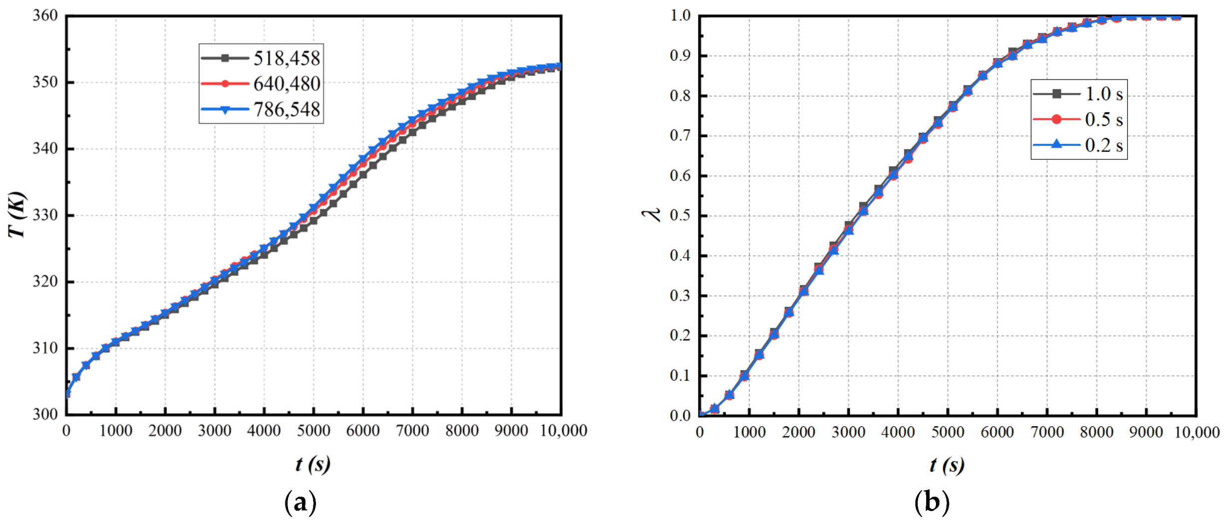
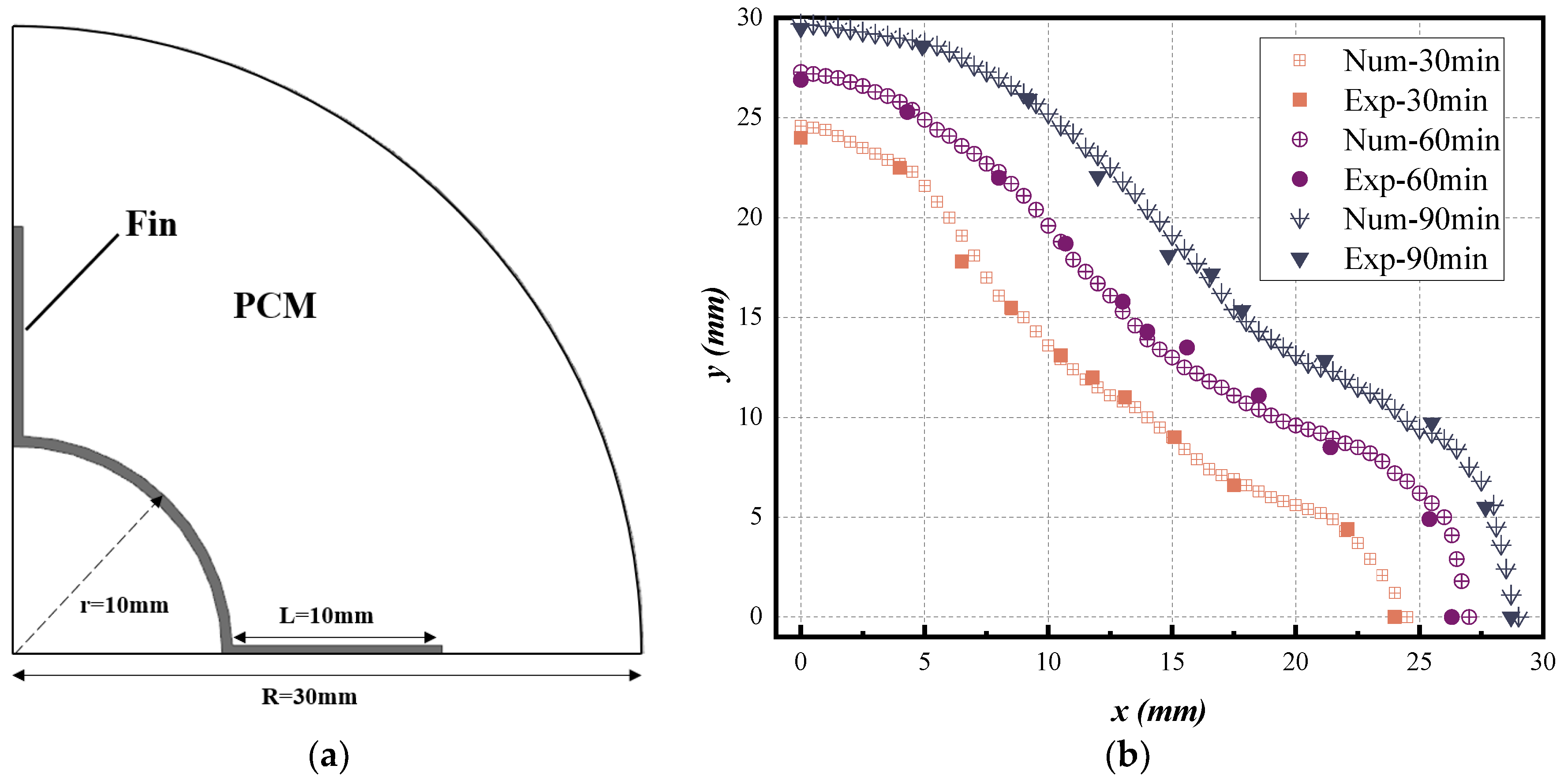
2.6. Model Validation

The reliability of the numerical model has been verified by the experimental results of Ismail et al. [47]. Ismail experimentally investigated the influence of the number, length and thickness of longitudinal fins on the solidification properties of PCM. In Ismail’s experiments, the finned tube was inserted in the PCM, the outer cylindrical surface was insulated, and the tube wall was kept at a constant temperature. The geometric details of the 1/4 finned tube are shown in Figure 4a,b, presenting the changes in the position of the solid–liquid interface at different times during the solidification process when the fin number is 4. The error between the numerical results and the experimental results is within 5.0%, which is within the acceptable error range. It is thus proven that the numerical calculation is reliable and accurate.

3. Results and Discussion

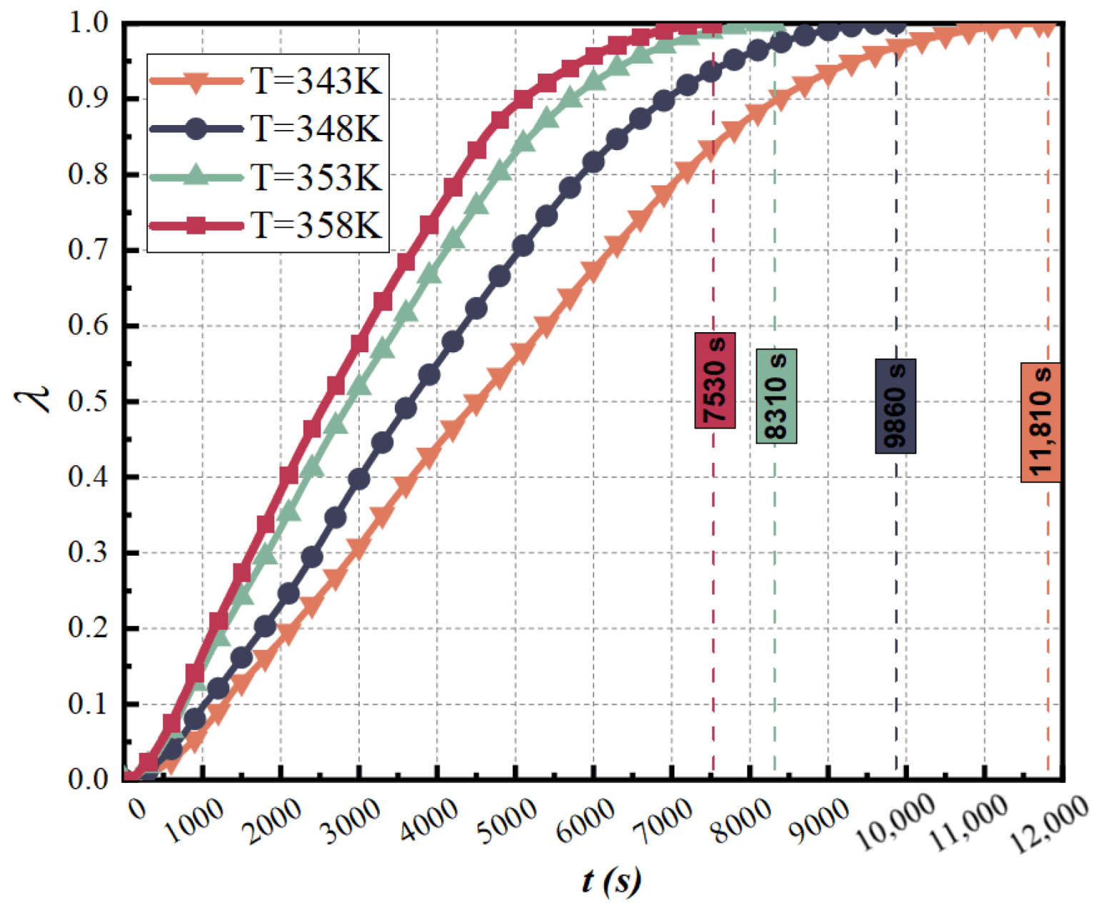
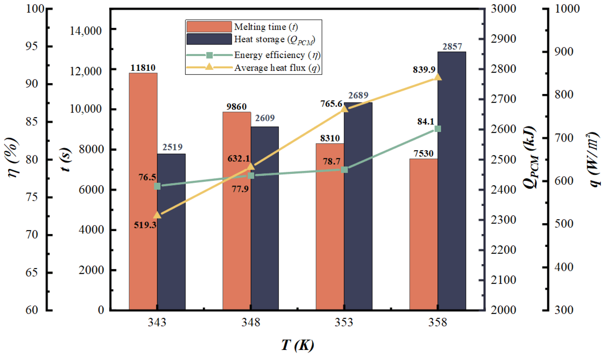
3.1. Influence of Inlet Temperature

In this paper, four different HTF inlet temperatures are set, and the influence of different inlet temperatures on the melting performance of fan-shaped finned tubes has been discussed. Figure 5 depicts the changing trend of the melting fraction when the inlet flow rate is 5 L/min and the inlet temperature is 343 K, 348 K, 353 K, and 358 K, respectively. It is evident that as the HTF inlet temperature increases, the time required for complete melting of the PCM decreases, which implies that the melting rate increases. It is mainly caused by the large temperature difference between PCM and HTF. The increase in temperature enhances the ability of the fins to conduct heat, and the heat transfer intensity between HTF and PCM is also enhanced due to the increase in temperature difference. As a result, the PCM on both sides of the fins will start to melt at a higher rate, which greatly saves heat storage time.
It can be seen from Figure 6 that the increase of the inlet temperature plays a key role in improving the melting characteristics of the PCM. When the temperatures are 343 K, 348 K, 353 K and 358 K, the total heat storage of the LHS device is 2519 kJ, 2608 kJ, 2689 kJ and 2857 kJ, respectively. Compared with the inlet temperature of 343 K, the heat storage at 348 K, 353 K, and 358 K is increased by 3.5%, 6.7%, and 13.4%, respectively, while the melting time of PCM is decreased by 16.5%, 29.6%, and 36.2%, respectively. It can be seen that with the increase of the inlet water temperature, the average heat flux density increases linearly, and the average increase is more than 20%. It shows that an appropriate increase in the inlet temperature can enhance the heat transfer performance of the fan-shaped fin tube and the melting performance of the PCM. It should be noted that with the increase of water temperature, the complete melting time does not continue to maintain a significant reduction, and the reduction rate shows a gradually decreasing trend. It shows that increasing the temperature has a critical value for the optimization of reducing the melting time, but still can improve the total heat storage and energy efficiency of the LHS unit. Especially when the heating temperature is increased from 353 K to 358 K, the heat storage and energy efficiency are significantly improved by 6.2% and 6.9%, respectively. Therefore, to maintain the efficient energy efficiency of the LHS system and as little heat storage time as possible, it is recommended to control the inlet water temperature to not lower than 353 K.

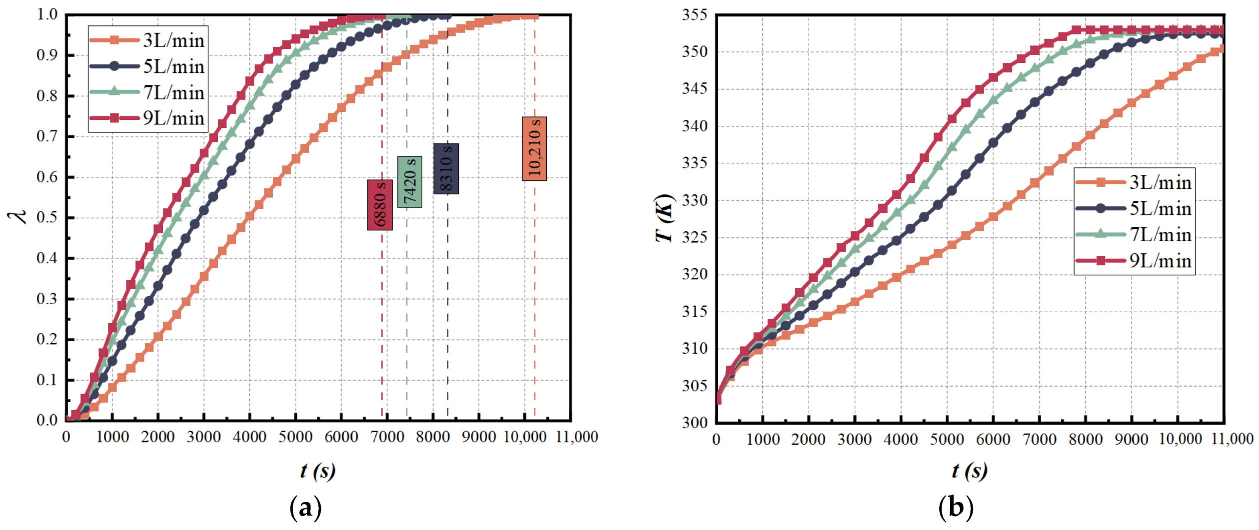
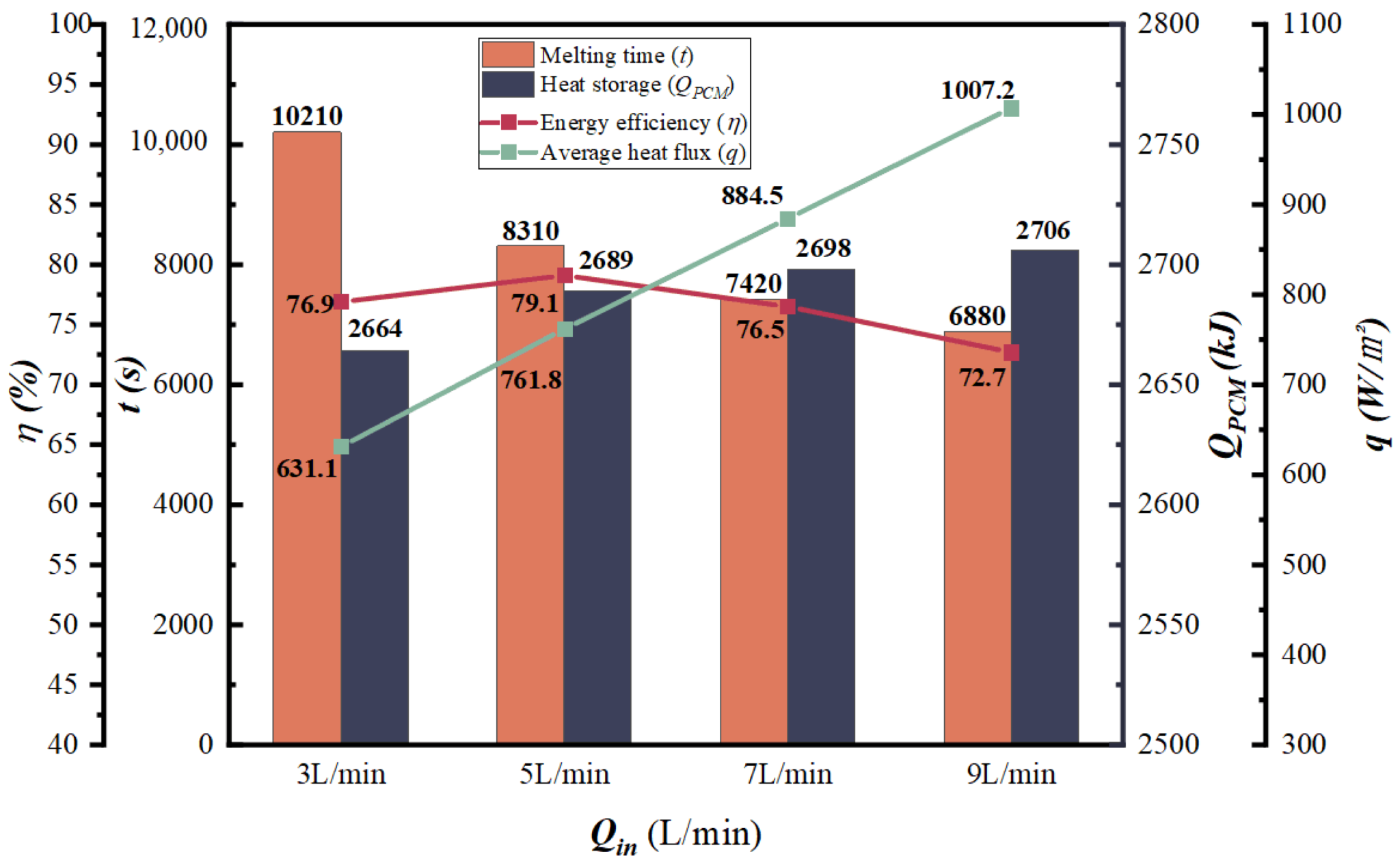
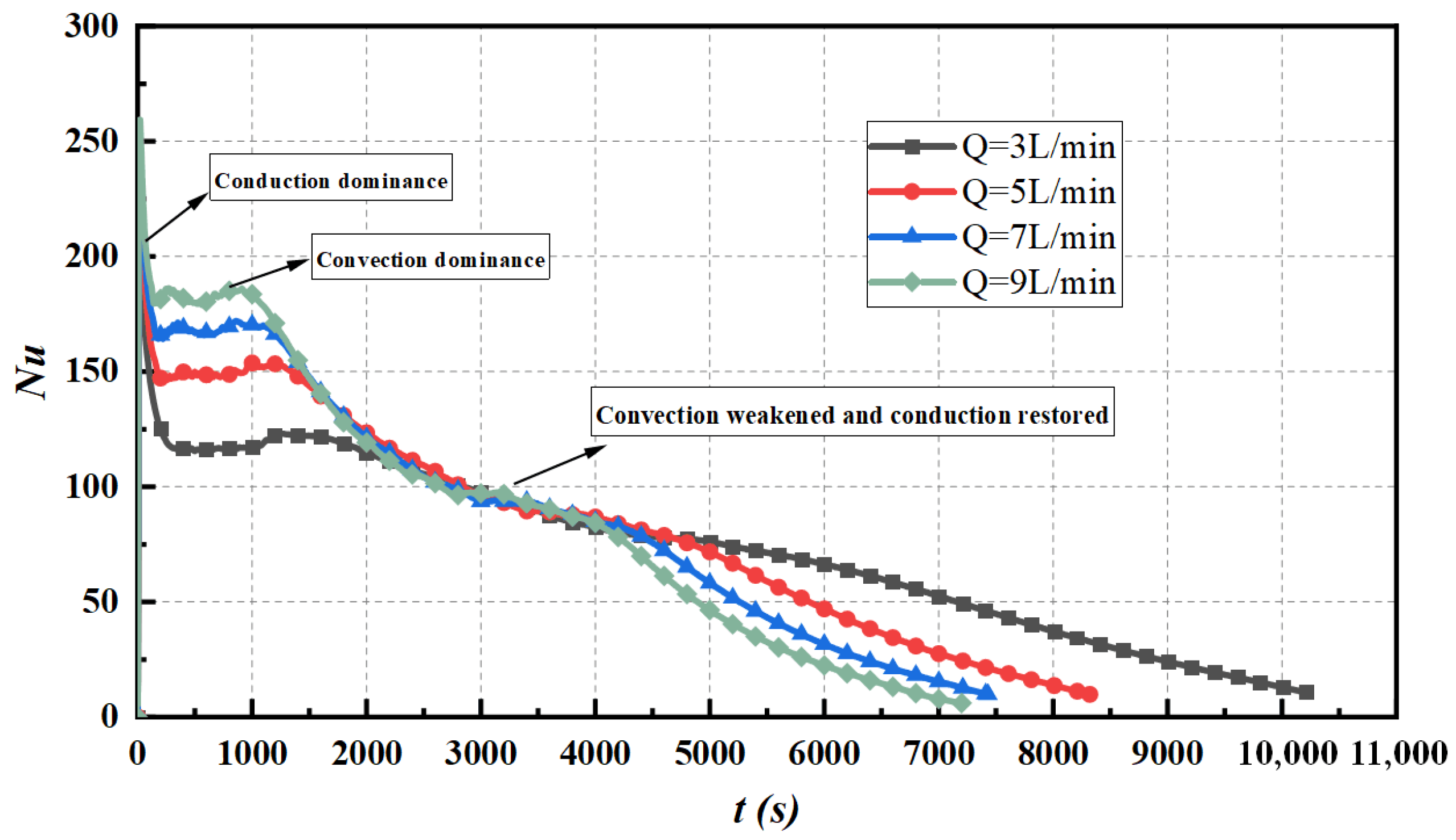
3.2. Influence of Inlet Flow Rate

In order to investigate whether the HTF inlet flow improves the heat storage process of the LHS fan-shaped heat storage tank, the HTF inlet temperature is stabilized at 353 K, and the inlet flow is set to 3 L/min, 5 L/min, 7 L/min and 9 L/min, respectively. Figure 7a,b show the melting fraction and temperature as a function of time, respectively. When the inlet flow rate increases gradually, the melting rate is significantly accelerated, and the temperature rise rate also increases gradually. When the flow rate is increased from 3 L/min to 9 L/min, the complete melting time is reduced by 18.6%, 27.3%, and 33.4%. This is because with the gradual increase of the inlet flow rate, the heat exchange between the HTF and the PCM per unit time increases accordingly. That is to say, the temperature of the PCM will rise faster per unit time, which means that the total heat storage of the PCM will increase accordingly. It is worth noting that when the inlet flow rate exceeds 3 L/min, the flow state of HTF in the copper tube is fully developed turbulent flow. However, the convective heat transfer coefficient will decrease slowly with the increase of the flow rate. It can be seen from Figure 8 that when the flow rate reaches 7 L/min and above, the increasing trend of the melting rate gradually slows down, and the energy efficiency begins to gradually decline, and the energy efficiency reaches its peak at 5 L/min. This indicates that the larger inlet flow rate is not necessarily better. Considering the economy and practicability, the flow rate of 5 L/min is the most suitable.
The change of Nusselt number with time can be used to characterize the intensity of convective heat transfer. Nu values can be expressed as [48]:
N u = Q ˙ ( t ) D h A ( T w T m ) k l
where Q is the instantaneous heat transfer rate, Dh is the characteristic length which is the difference between the diameter of the shell and the outer diameter of the HTF tube, A is the heat exchange area, kl is the thermal conductivity of the liquid PCM, Tm and Tw are the melting temperature and tube wall temperature.
Figure 9 shows the time history of the Nusselt number for different inlet flow rates at an inlet temperature of 353 K. According to the change of Nusselt number, the global melting can be divided into three stages: thermal conduction, convection, convection weakening and thermal conduction recovery. At the beginning of the heat storage stage, thermal conduction dominates, so there is a large Nusselt value at the beginning of the heat transfer process. This is because at the beginning of melting, there is only a very thin liquid film on the surface of the melt, and the thermal resistance is very small, which also leads to a very fast melting rate in the initial stage. The higher the melting degree of PCM, the greater the heat transfer resistance at the solid–liquid interface, and the weaker the effect of heat conduction. The Nusselt number drops sharply at this moment. The decline of the Nusselt number stops with the appearance of convective motion in the melt, followed by the convective heat transfer gradually becoming dominant, and the melting process enters the second stage. During the convection phase, the Nusselt number remains almost constant for a period of time. Over time, the liquid PCM accumulated in the upper layer, the thermal resistance increased, and the convection intensity began to weaken. When the top solid PCM melts completely, the local convection in this region disappears, and the conduction mechanism between liquids begins to recover gradually. The change of the Nusselt number shows a slow downward trend. It can be clearly seen from Figure 9 that the larger the HTF flow velocity, the larger the Nusselt number in the convection stage, indicating that the convection process is more intense.

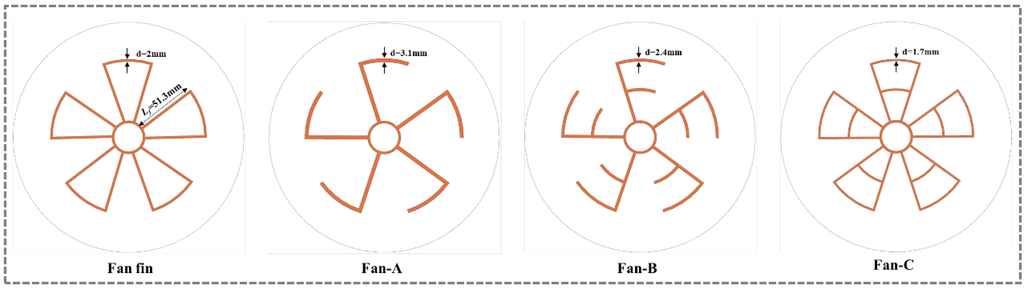
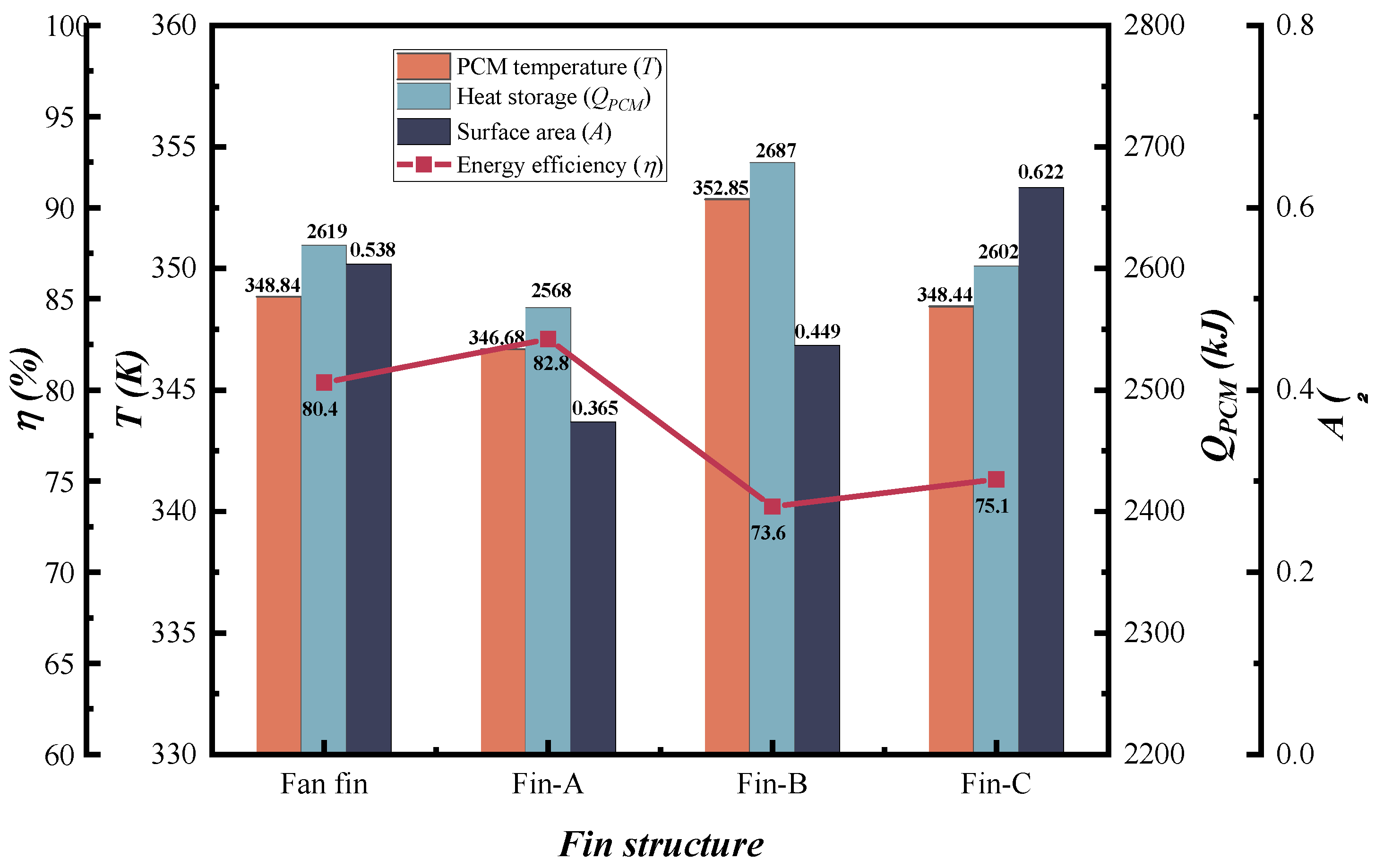
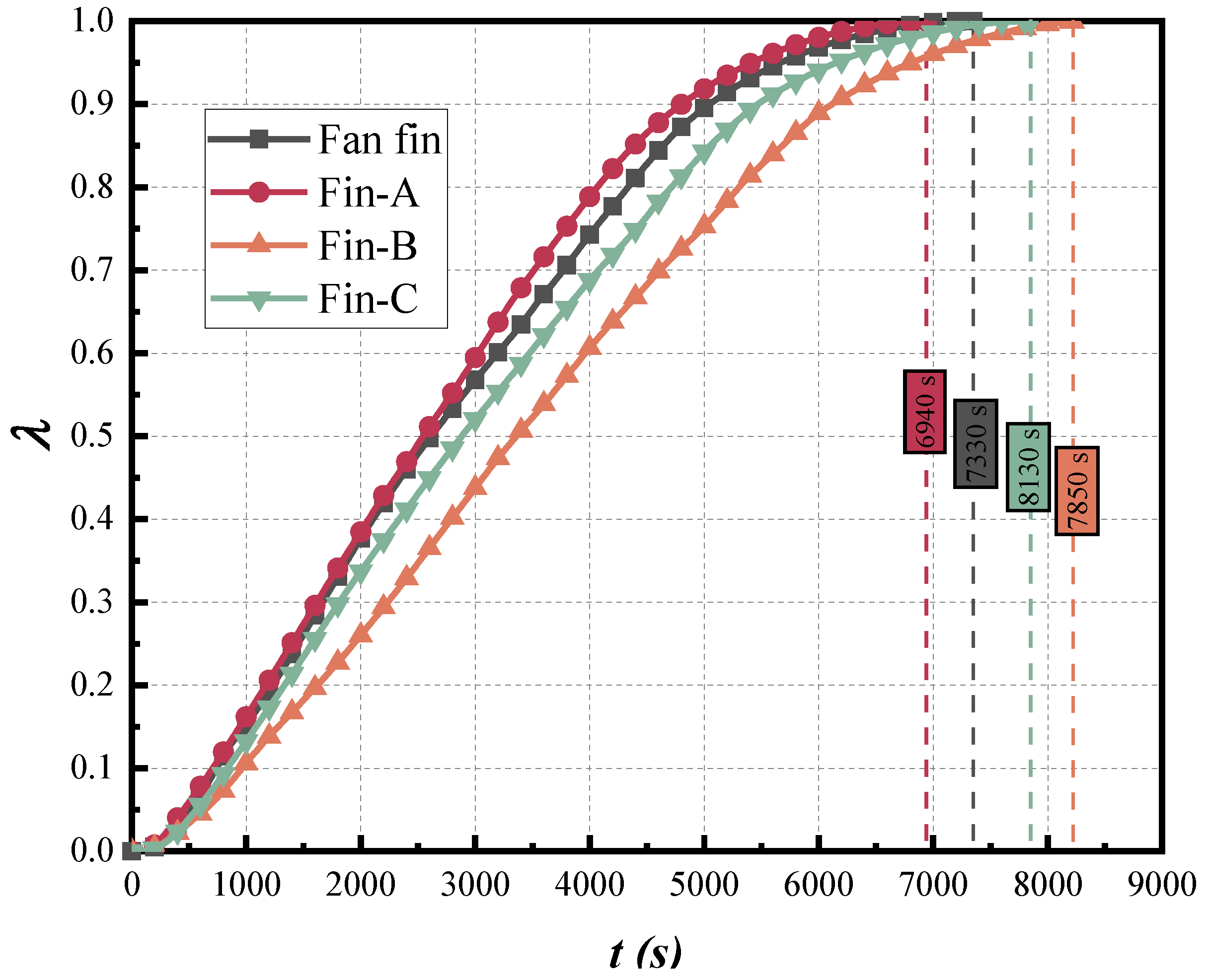
3.3. Optimization of Fin Structure

On the basis of fan-shaped fins, several novel fin shapes have been evolved, as shown in Figure 10. Under the premise of ensuring the same fin volume, the effect of different fin shapes on the melting of PCM has been studied.
Figure 11 shows the melting front and temperature distribution of different fin structures at different times and the cross-sectional view at a height of 0.1 mm. At an inlet temperature of 353 K and an inlet flow of 5 L/min, the four fin structures can conduct heat quickly and accelerate the melting of the surrounding PCM. It can be seen intuitively that the shapes and positions of the melting front interface and the temperature distribution interface at different times are basically similar. Due to the different shapes of the fins, there are differences in the melting of the PCM in different regions, but they all show similar melting inhomogeneities. In the early stage of heat storage, the melting process first occurs near the wall of the heat exchange tube and around the heat conduction fins. It indicates that the PCM close to the fin has a higher fraction of local melting regardless of the fin shape. The degree of melting of the PCM near the fins is higher than that far from the fins, which proves that the fin promotes the melting of PCM and also leads to a continuous wave-like melting front on the melting profile. It is caused by the uneven degree of melting caused by local eddy currents and natural convection movements. Due to the change in density, the liquid PCM flows upward under the action of buoyancy, which promotes the generation of natural convection motion, thereby driving the melting of the surrounding solid PCM. When the PCM near the tube wall and at the top of the cavity is melted, the liquid PCM on the outside of the copper tube will flow upward along the tube wall, and the liquid PCM at the solid-liquid interface will flow downward under the influence of gravity, resulting in the formation of a distinct clockwise circulating vortex. With the deepening of the melting process, the convective circulation range gradually expands, and the wavy twist position gradually moves downward.
At t = 1800 s, the heat is transferred from the HTF to the paraffin in the cavity through the fin, and the paraffin wax near the fins begins to melt first. The solid-liquid interface presents different melting profiles due to different fin shapes. The paraffin farther away from the fin was obviously underheated, and the local melting fraction was also lower than that near the fin end. Over time (t = 3600 s and t = 5400 s), more and more paraffin began to melt. The paraffin wax around Fin-A melts the fastest, followed by Fan fin. Fan fin and Fin-A have higher melting rates. It may be due to the presence of redundant fins resulting in the formation of enclosed spaces that weaken natural convection during paraffin melting. Under the premise of the same fin volume, although the surface area of the fin is increased, the effect of promoting the heat conduction is less than the effect of the weakening of natural convection. It can be clearly seen from Figure 11 that the melting profiles of Fan-A and Fan-B are significantly different. Although the two have similar fin shapes, the greater part of Fan-B than Fan-A blocks the convective movement inside the cavity, resulting in a slower heat storage time than Fan-A.
Figure 12 shows the variation of the paraffin liquid phase fraction over time in four different finned tubes. It can be intuitively seen that the complete melting time of PCM in the Fin-A tube is the shortest, only 6940 s, followed by Fan fin, Fin-B and Fin-C. There are 5.3%, 14.6% and 11.6% improvements compared to Fan fin, Fin-B, and Fin-C, respectively. Figure 13 visually depicts the comparison of heat storage capacity and energy efficiency of different finned tube structures. Among them, the fin structure of Fin-B enables the entire LHS system to obtain maximum heat storage. This is the case because, under the same working conditions, the average temperature of the PCM in the Fin-B structure at the end of the heat storage is the highest, which also leads to a higher heat storage from the point of view of the heat transfer equation. Overall, Fin-A has the smallest fin surface area but the highest degree of melting. Although the heat storage capacity is slightly reduced, the energy storage efficiency is 2.98% higher than that of the Fan fin structure. To further improve the melting performance of the LHS system, the fin structure of Fin-A can be further studied in the future.

4. Conclusions

A new type of fan-finned tube LHS device considering natural convection is numerically investigated. Numerical simulation of the melting process of paraffin in the unit is carried out. The melting properties are studied under different inlet conditions, and the melting characteristics, such as melting fraction, temperature distribution, and energy efficiency under different conditions, are compared and analyzed. The fan-shaped fin is optimized according to the fin structure, and three different fin structures are considered to further strengthen the solid-liquid phase transition process. The important conclusions from this research are as follows:
(1)
When the inlet temperature increases from 343 K to 348 K, 353 K and 358 K, the heat storage capacity of PCM is increased by 3.5%, 6.7%, and 13.4%, respectively. The melting time of PCM is reduced by 16.5%, 29.6%, and 36.2%, respectively. When the inlet temperature increases from 353 K to 358 K, although the melting time is shortened slightly, the energy efficiency and heat storage show a large increase. This shows that increasing the temperature has a critical value for the optimization of shortening the melting time, but it can still improve the heat storage efficiency of the LHS system.
(2)
When the inlet flow rate increases from 3 L/min to 9 L/min, the melting time of PCM is shortened by 18.6%, 27.3%, and 33.4%, the energy efficiency first increases and then decreases. The energy efficiency reaches the maximum at 5 L/min value. The larger the HTF flow, the larger the Nusselt number in the convective stage, indicating that the convective process is more intense.
(3)
The complete melting time of PCM in Fin-A tube is shortened by 5.3%, 14.6%, and 11.6% compared with Fan fin, Fin-B, and Fin-C, respectively. On the whole, under the same fin volume, Fin-A has the highest melting degree. Although the heat storage is slightly decreased, the energy efficiency is 2.98% higher than that of the Fan fin.

Author Contributions

Conceptualization, Q.M.; methodology, Q.M. and X.H.; software, X.H. and Y.Z.; validation, X.H. and Y.Z.; formal analysis, X.H.; investigation, X.H.; resources, X.H.; data curation, X.H.; writing—original draft preparation, X.H.; writing—review and editing, X.H.; visualization, Q.M., X.H. and Y.Z.; supervision, Q.M.; project administration, Q.M.; funding acquisition, Q.M. All authors have read and agreed to the published version of the manuscript.

Funding

This research received no external funding.

Institutional Review Board Statement

Not applicable.

Informed Consent Statement

Not applicable.

Data Availability Statement

Not applicable.

Acknowledgments

This work was supported by the National Natural Science Foundation of China (No. 51876147).

Conflicts of Interest

The authors declare no conflict of interest.

Nomenclature

Abbreviation
TESThermal Energy Storage
LHSLatent Heat Storage
PCM Phase Change Material
HTFHeat Transfer Fluid
Symbols
H Heat storage unit height (mm)
R Shell radius (mm)
T m Melting temperature (K)
t Melting time (s)
u Velocity vector (m/s)
g Gravity (m/s2)
c p Specific heat capacity (J/kg·K)
c p , s Solid specific heat of paraffin (J/kg·K)
c p , l Liquid specific heat of paraffin (J/kg·K)
c p , f Specific heat of HTF (J/kg·K)
P Pressure (Pa)
k Coefficient of thermal conductivity (W/m·K)
L Latent heat of PCM (J/kg)
A Heat exchange area (m2)
Q Heat storage capacity (kJ)
q Average heat flux (W/m2)
D h Characteristic length
Greek symbols
Φ 1 Copper tube inner diameter (mm)
Φ 2 shell outer diameter (mm)
λ Melting fraction
ρ Density (kg/m3)
μ Dynamic viscosity (kg/m·s)
β Coefficient of thermal expansion (1/K)
η Energy efficiency (%)
Ω Outer surface of the device housing
Subscript
0 Initial
m Melting
i n Inlet
o u t Outlet
l i q u i d Liquidus
s o l i d Solidus
f Fluid
w Wall
i n i Initial

References

  1. He, W.; Tao, L.; Han, L.; Sun, Y.; Campana, P.E.; Yan, J. Optimal analysis of a hybrid renewable power system for a remote island. Renew. Energy 2021, 179, 96–104. [Google Scholar] [CrossRef]
  2. Mao, Q. Recent developments in geometrical configurations of thermal energy storage for concentrating solar power plant. Renew. Sustain. Energy Rev. 2016, 59, 320–327. [Google Scholar] [CrossRef]
  3. Mao, Q.; Zhang, Y. Thermal energy storage performance of a three-PCM cascade tank in a high-temperature packed bed system. Renew. Energy 2020, 152, 110–119. [Google Scholar] [CrossRef]
  4. Wang, L.; Guo, L.; Ren, J.; Kong, X. Using of heat thermal storage of PCM and solar energy for distributed clean building heating: A multi-level scale-up research. Appl. Energy 2022, 321, 119345. [Google Scholar] [CrossRef]
  5. Kim, S.H.; Heu, C.S.; Mok, J.Y.; Kang, S.-W.; Kim, D.R. Enhanced thermal performance of phase change material-integrated fin-type heat sinks for high power electronics cooling. Int. J. Heat Mass Transf. 2022, 184, 122257. [Google Scholar] [CrossRef]
  6. Wen, X.; Ji, J.; Li, Z.; Song, Z. Performance analysis of a concentrated system with series photovoltaic/thermal module and solar thermal collector integrated with PCM and TEG. Energy 2022, 249, 123777. [Google Scholar] [CrossRef]
  7. De Falco, M.; Capocelli, M.; Giannattasio, A. Performance analysis of an innovative PCM-based device for cold storage in the civil air conditioning. Energy Build. 2016, 122, 1–10. [Google Scholar] [CrossRef]
  8. Malik, F.K.; Khan, M.M.; Ahmed, H.F.; Irfan, M.; Ahad, I.U. Performance characteristics of PCM based thermal energy storage system for fluctuating waste heat sources. Case Stud. Therm. Eng. 2022, 34, 102012. [Google Scholar] [CrossRef]
  9. Wan, X.; Wang, F. Udayraj Numerical analysis of cooling effect of hybrid cooling clothing incorporated with phase change material (PCM) packs and air ventilation fans. Int. J. Heat Mass Transf. 2018, 126, 636–648. [Google Scholar] [CrossRef]
  10. Parsazadeh, M.; Duan, X. Numerical Study of a Hybrid Thermal Insulation with Phase Change Material for Subsea Pipelines. In Proceedings of the ASME 2016 International Mechanical Engineering Congress and Exposition, Phoenix, AZ, USA, 11–17 November 2016. [Google Scholar] [CrossRef]
  11. Yang, X.; Lu, T.; Kim, T. Temperature effects on the effective thermal conductivity of phase change materials with two distinctive phases. Int. Commun. Heat Mass Transf. 2011, 38, 1344–1348. [Google Scholar] [CrossRef]
  12. Sun, B.; Liu, Z.; Ji, X.; Gao, L.; Che, D. Thermal energy storage characteristics of packed bed encapsulating spherical capsules with composite phase change materials. Appl. Therm. Eng. 2022, 201, 117659. [Google Scholar] [CrossRef]
  13. Kant, K.; Shukla, A.; Sharma, A.; Biwole, P.H. Heat transfer study of phase change materials with graphene nanoparticle for thermal energy storage. Sol. Energy 2017, 146, 453–463. [Google Scholar] [CrossRef]
  14. Zhao, Y.; Zhao, C.Y.; Xu, Z.G.; Xu, H.J. Modeling metal foam enhanced phase change heat transfer in thermal energy storage by using phase field method. Int. J. Heat Mass Transf. 2016, 99, 170–181. [Google Scholar] [CrossRef]
  15. Li, Y.; Jiang, S.; Wang, C.; Zhu, Q. Effect of EG particle size on the thermal properties of NaNO3–NaCl/EG shaped composite phase change materials. Energy 2022, 239, 122062. [Google Scholar] [CrossRef]
  16. Mao, Q.; Li, Y.; Li, G.; Badiei, A. Study on the influence of tank structure and fin configuration on heat transfer performance of phase change thermal storage system. Energy 2021, 235, 121382. [Google Scholar] [CrossRef]
  17. Kirincic, M.; Trp, A.; Lenic, K. Influence of natural convection during melting and solidification of paraffin in a longitudinally finned shell-and-tube latent thermal energy storage on the applicability of developed numerical models. Renew. Energy 2021, 179, 1329–1344. [Google Scholar] [CrossRef]
  18. Pássaro, J.; Rebola, A.; Coelho, L.; Conde, J.; Evangelakis, G.; Prouskas, C.; Papageorgiou, D.; Zisopoulou, A.; Lagaris, I. Effect of fins and nanoparticles in the discharge performance of PCM thermal storage system with a multi pass finned tube heat exchange. Appl. Therm. Eng. 2022, 212, 118569. [Google Scholar] [CrossRef]
  19. Alizadeh, M.; Shahavi, M.H.; Ganji, D.D. Performance enhancement of nano PCM solidification in a hexagonal storage unit with innovative fin shapes dealing with time-dependent boundary conditions. Energy Rep. 2022, 8, 8200–8214. [Google Scholar] [CrossRef]
  20. Kirincic, M.; Trp, A.; Lenic, K. Numerical evaluation of the latent heat thermal energy storage performance enhancement by installing longitudinal fins. J. Energy Storage 2021, 42, 103085. [Google Scholar] [CrossRef]
  21. Medrano, M.; Yilmaz, M.O.; Nogués, M.; Martorell, I.; Roca, J.; Cabeza, L.F. Experimental evaluation of commercial heat exchangers for use as PCM thermal storage systems. Appl. Energy 2009, 86, 2047–2055. [Google Scholar] [CrossRef]
  22. Sun, Z.; Fan, R.; Zheng, N. Thermal management of a simulated battery with the compound use of phase change material and fins: Experimental and numerical investigations. Int. J. Therm. Sci. 2021, 165, 106945. [Google Scholar] [CrossRef]
  23. Mekrisuh, K.U.; Giri, S.; Udayraj; Singh, D.; Rakshit, D. Optimal design of the phase change material based thermal energy storage systems: Efficacy of fins and/or nanoparticles for performance enhancement. J. Energy Storage 2021, 33, 102126. [Google Scholar] [CrossRef]
  24. Tay, N.H.S.; Bruno, F.; Belusko, M. Comparison of pinned and finned tubes in a phase change thermal energy storage system using CFD. Appl. Energy 2013, 104, 79–86. [Google Scholar] [CrossRef]
  25. Yang, X.; Lu, Z.; Bai, Q.; Zhang, Q.; Jin, L.; Yan, J. Thermal performance of a shell-and-tube latent heat thermal energy storage unit: Role of annular fins. Appl. Energy 2017, 202, 558–570. [Google Scholar] [CrossRef]
  26. Guo, J.; Liu, Z.; Yang, B.; Yang, X.; Yan, J. Melting assessment on the angled fin design for a novel latent heat thermal energy storage tube. Renew. Energy 2022, 183, 406–422. [Google Scholar] [CrossRef]
  27. Darzi, A.A.R.; Jourabian, M.; Farhadi, M. Melting and solidification of PCM enhanced by radial conductive fins and nanoparticles in cylindrical annulus. Energy Convers. Manag. 2016, 118, 253–263. [Google Scholar] [CrossRef]
  28. Modi, N.; Wang, X.; Negnevitsky, M.; Cao, F. Melting characteristics of a longitudinally finned-tube horizontal latent heat thermal energy storage system. Sol. Energy 2021, 230, 333–344. [Google Scholar] [CrossRef]
  29. Qin, Z.; Low, Z.H.; Ji, C.; Duan, F. Efficacy of angled metallic fins for enhancing phase change material melting. Int. Commun. Heat Mass Transf. 2022, 132, 105921. [Google Scholar] [CrossRef]
  30. Ranjbar, A.M.; Pouransari, Z.; Siavashi, M. Improved design of heat sink including porous pin fins with different arrangements: A numerical turbulent flow and heat transfer study. Appl. Therm. Eng. 2021, 198, 117519. [Google Scholar] [CrossRef]
  31. Mahdi, J.M.; Lohrasbi, S.; Nsofor, E.C. Hybrid heat transfer enhancement for latent-heat thermal energy storage systems: A review. Int. J. Heat Mass Transf. 2019, 137, 630–649. [Google Scholar] [CrossRef]
  32. Akhilesh, R.; Narasimhan, A.; Balaji, C. Method to improve geometry for heat transfer enhancement in PCM composite heat sinks. Int. J. Heat Mass Transf. 2005, 48, 2759–2770. [Google Scholar] [CrossRef]
  33. Wang, P.; Yao, H.; Lan, Z.; Peng, Z.; Huang, Y.; Ding, Y. Numerical investigation of PCM melting process in sleeve tube with internal fins. Energy Convers. Manag. 2016, 110, 428–435. [Google Scholar] [CrossRef]
  34. Shahsavar, A.; Goodarzi, A.; Mohammed, H.I.; Shirneshan, A.; Talebizadehsardari, P. Thermal performance evaluation of non-uniform fin array in a finned double-pipe latent heat storage system. Energy 2020, 193, 116800. [Google Scholar] [CrossRef]
  35. Yagci, O.K.; Avci, M.; Aydin, O. Melting and solidification of PCM in a tube-in-shell unit: Effect of fin edge lengths’ ratio. J. Energy Storage 2019, 24, 100802. [Google Scholar] [CrossRef]
  36. Abdulateef, A.M.; Mat, S.; Sopian, K.; Abdulateef, J.; Gitan, A.A. Experimental and computational study of melting phase-change material in a triplex tube heat exchanger with longitudinal/triangular fins. Sol. Energy 2017, 155, 142–153. [Google Scholar] [CrossRef]
  37. Calamas, D.; Baker, J. Tree-like branching fins: Performance and natural convective heat transfer behavior. Int. J. Heat Mass Transf. 2013, 62, 350–361. [Google Scholar] [CrossRef]
  38. Konan, H.; Cetkin, E. Snowflake shaped high-conductivity inserts for heat transfer enhancement. Int. J. Heat Mass Transf. 2018, 127, 473–482. [Google Scholar] [CrossRef]
  39. Alizadeh, M.; Hosseinzadeh, K.; Shahavi, M.; Ganji, D. Solidification acceleration in a triplex-tube latent heat thermal energy storage system using V-shaped fin and nano-enhanced phase change material. Appl. Therm. Eng. 2019, 163, 114436. [Google Scholar] [CrossRef]
  40. Pizzolato, A.; Sharma, A.; Maute, K.; Sciacovelli, A.; Verda, V. Design of effective fins for fast PCM melting and solidification in shell-and-tube latent heat thermal energy storage through topology optimization. Appl. Energy 2017, 208, 210–227. [Google Scholar] [CrossRef]
  41. Al-Mudhafar, A.H.; Nowakowski, A.F.; Nicolleau, F.C. Enhancing the thermal performance of PCM in a shell and tube latent heat energy storage system by utilizing innovative fins. Energy Rep. 2021, 7, 120–126. [Google Scholar] [CrossRef]
  42. Liu, Z.; Liu, Z.; Guo, J.; Wang, F.; Yang, X.; Yan, J. Innovative ladder-shaped fin design on a latent heat storage device for waste heat recovery. Appl. Energy 2022, 321, 119300. [Google Scholar] [CrossRef]
  43. Ma, J.; Xu, H.; Liu, S.; Peng, H.; Ling, X. Numerical study on solidification behavior and exergy analysis of a latent heat storage unit with innovative circular superimposed longitudinal fins. Int. J. Heat Mass Transf. 2021, 169, 120949. [Google Scholar] [CrossRef]
  44. Mao, Q.; Hu, X.; Li, T. Study on heat storage performance of a novel vertical shell and multi-finned tube tank. Renew. Energy 2022, 193, 76–88. [Google Scholar] [CrossRef]
  45. Huang, Y.; Cao, D.; Sun, D.; Liu, X. Experimental and numerical studies on the heat transfer improvement of a latent heat storage unit using gradient tree-shaped fins. Int. J. Heat Mass Transf. 2022, 182, 121920. [Google Scholar] [CrossRef]
  46. Younsi, Z.; Naji, H. A numerical investigation of melting phase change process via the enthalpy-porosity approach: Application to hydrated salts. Int. Commun. Heat Mass Transf. 2017, 86, 12–24. [Google Scholar] [CrossRef]
  47. Ismail, K.A.R.; Alves, C.L.F.; Modesto, M.S. Numerical and experimental study on the solidification of PCM around a vertical axially finned isothermal cylinder. Appl. Therm. Eng. 2001, 21, 53–77. [Google Scholar] [CrossRef]
  48. Safari, V.; Abolghasemi, H.; Kamkari, B. Experimental and numerical investigations of thermal performance enhancement in a latent heat storage heat exchanger using bifurcated and straight fins. Renew. Energy 2021, 174, 102–121. [Google Scholar] [CrossRef]
Figure 1. Evolution history of fan-shaped finned tubes.
Energies 15 05682 g001
Figure 2. Physical model of the LHS unit (a) Physical model (b) Computational domains.
Energies 15 05682 g002
Figure 3. Grid independence and time step independence check (a) Grid size (b) Time step.
Energies 15 05682 g003
Figure 4. Experiment and model validation (a) The geometric details of the 1/4 finned tube (b) Changes in the position of the solid-liquid interface.
Energies 15 05682 g004
Figure 5. Variation of PCM melting fraction at different inlet temperatures.
Energies 15 05682 g005
Figure 6. Comparison of PCM melting properties under different inlet temperatures.
Energies 15 05682 g006
Figure 7. Variation of PCM melting fraction and temperature at different inlet flow rates (a) Melting fraction (b) Average temperature.
Energies 15 05682 g007
Figure 8. Comparison of PCM melting properties under different inlet flow rates.
Energies 15 05682 g008
Figure 9. Variation of Nusselt number when the wall temperature is 353 K.
Energies 15 05682 g009
Figure 10. Schematic diagram of different fin structures.
Energies 15 05682 g010
Figure 11. PCM melting front and temperature distribution at different times.
Energies 15 05682 g011
Figure 12. Variation of PCM melting fraction under different fin structures.
Energies 15 05682 g012
Figure 13. Comparison of PCM melting properties under different fin structures.
Energies 15 05682 g013
Table 1. Material physical properties.
MaterialsPCM (Paraffin)Fin (Cooper)
Density (kg/m3)8858978
Thermal conductivity (W/m·K)0.279387.6
Specific heat capacity (J/kg·K)3085 (s) 2106 (L)381
Latent heat (J/kg)172,620-
Melting range (K)321–323-
Viscosity (kg/m·s)1.72 × 10−5-
Thermal expansion coefficient (1/K)0.0006-
Publisher’s Note: MDPI stays neutral with regard to jurisdictional claims in published maps and institutional affiliations.

