
Heat Transfer Enhancement of Phase Change Material in Triple-Tube Latent Heat Thermal Energy Storage Units: Operating Modes and Fin Configurations

Abstract
:1. Introduction
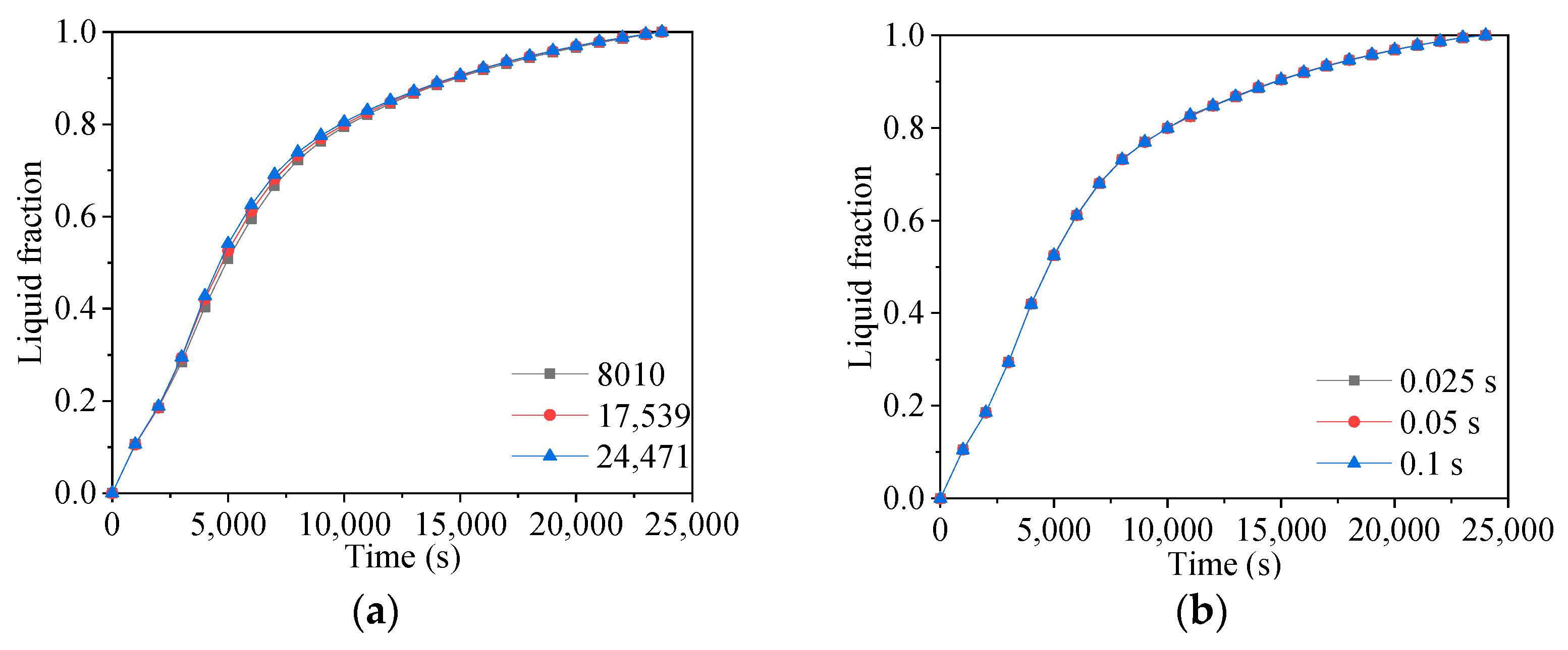
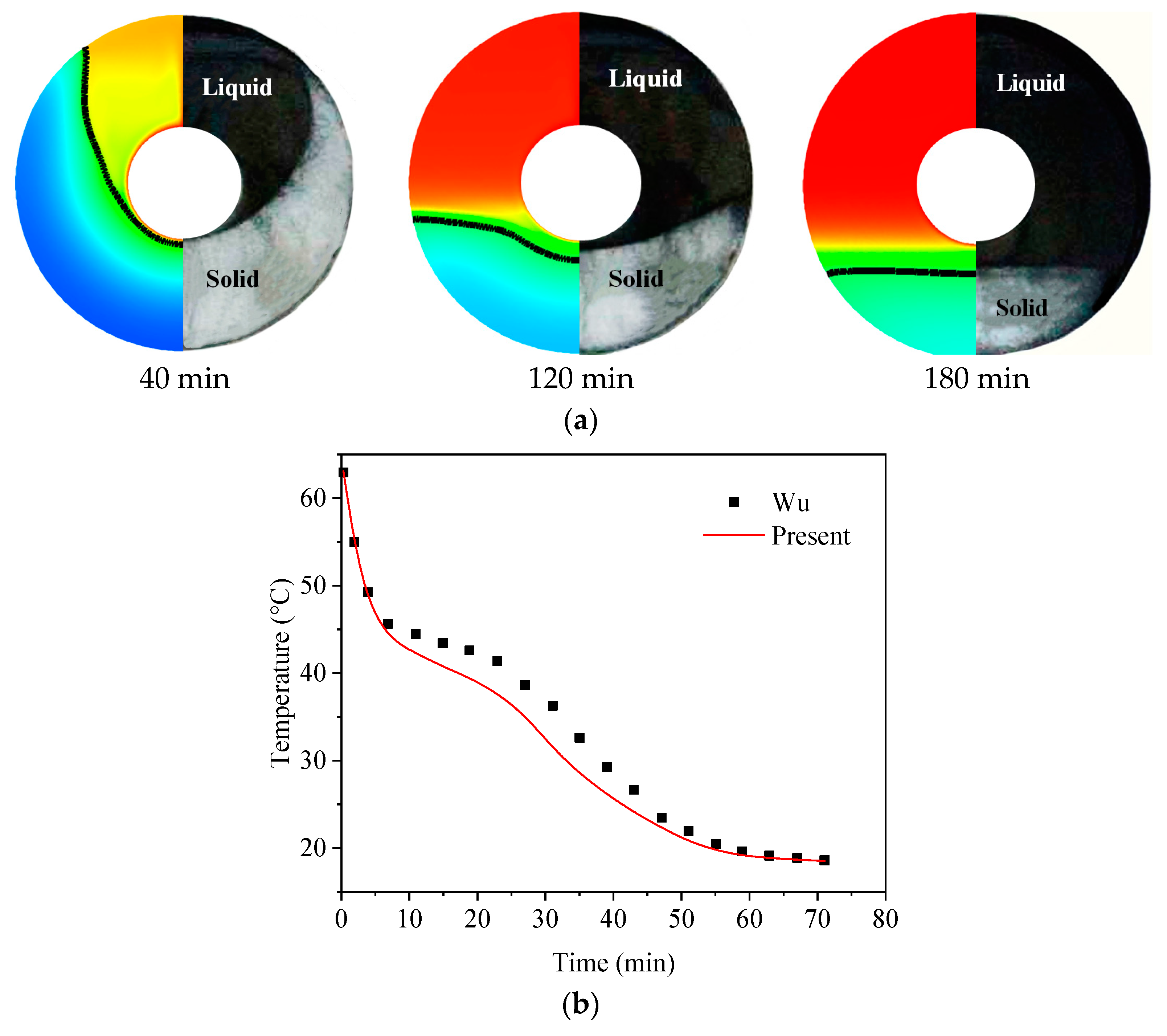
2. Computational Approaches and Verification
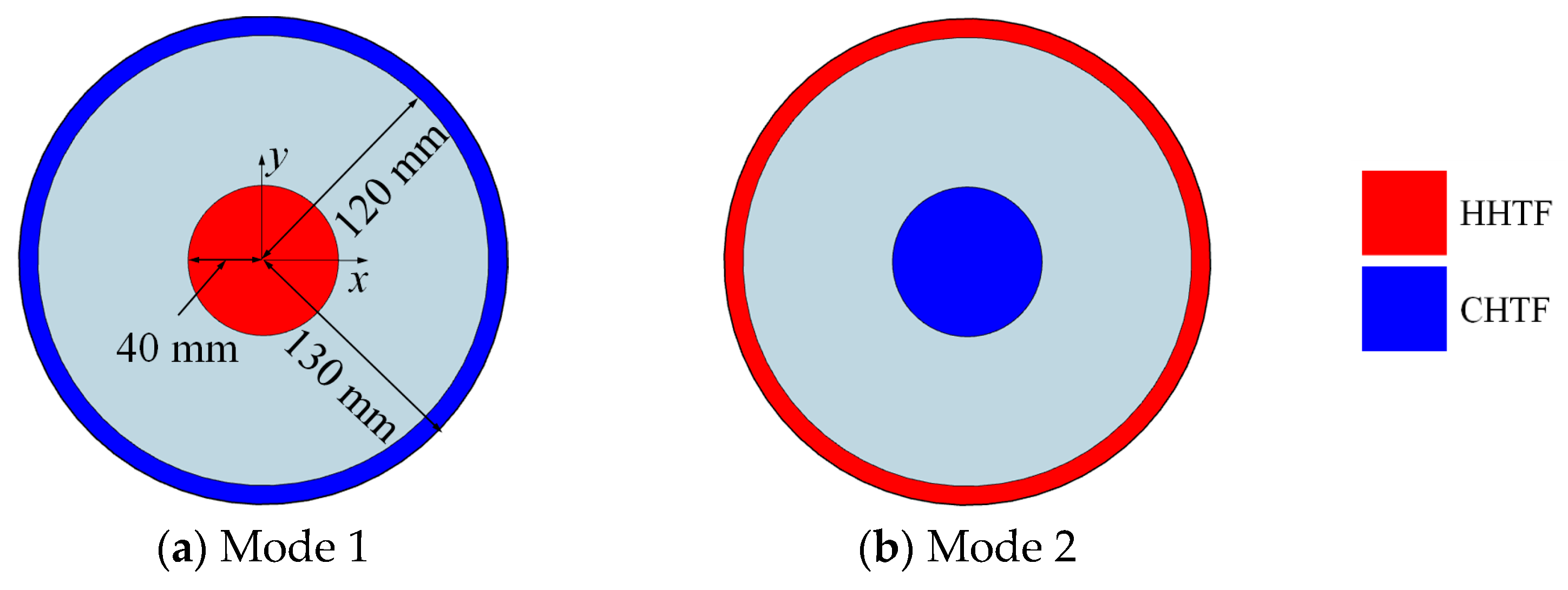
2.1. Numerical Model and Operating Modes
2.2. Mathematical Modeling
- The PCMs is pure and homogeneous.
- The liquid phase of the PCMs is a Newtonian and incompressible fluid.
- The volume change due to liquid-solid phase change is negligible.
- The natural convection in the liquid phase is laminar and two-dimensional.
- (a)
- Continuity equation
- (b)
- Momentum equation
- (c)
- Energy equation
3. Results
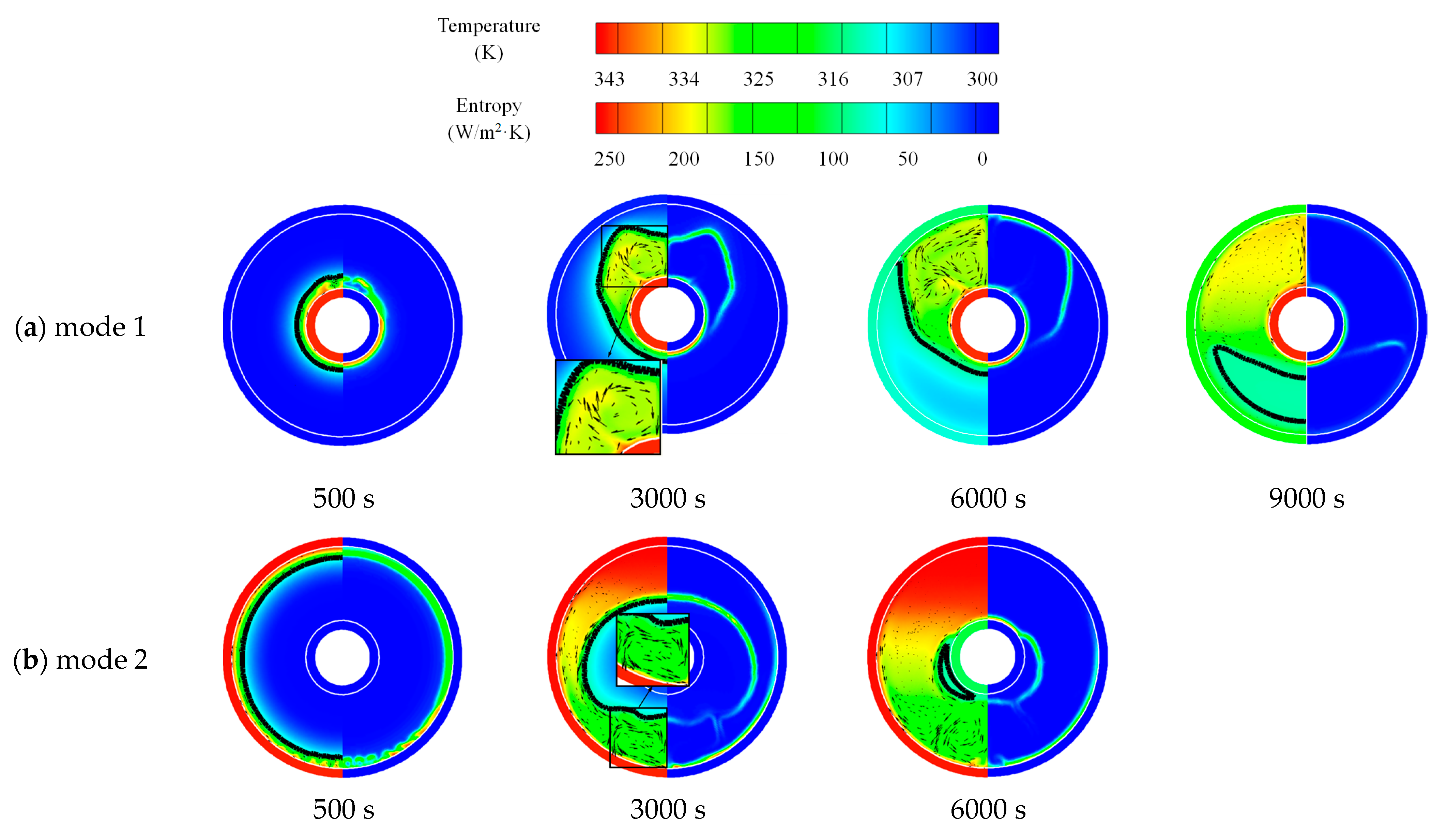
3.1. Comparison of No-Fin Cases with Two Operating Modes
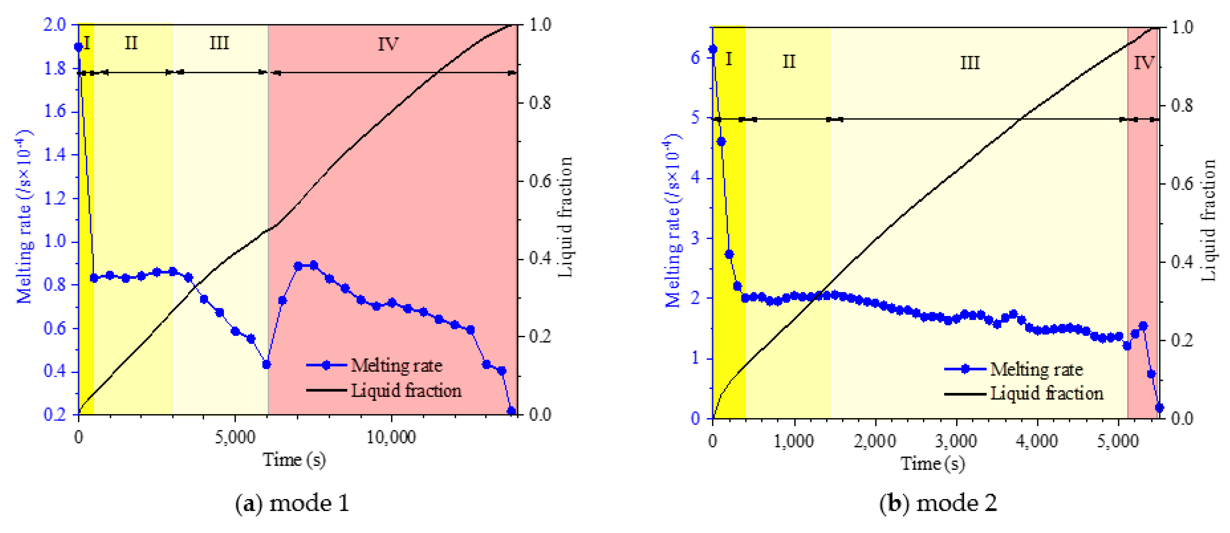
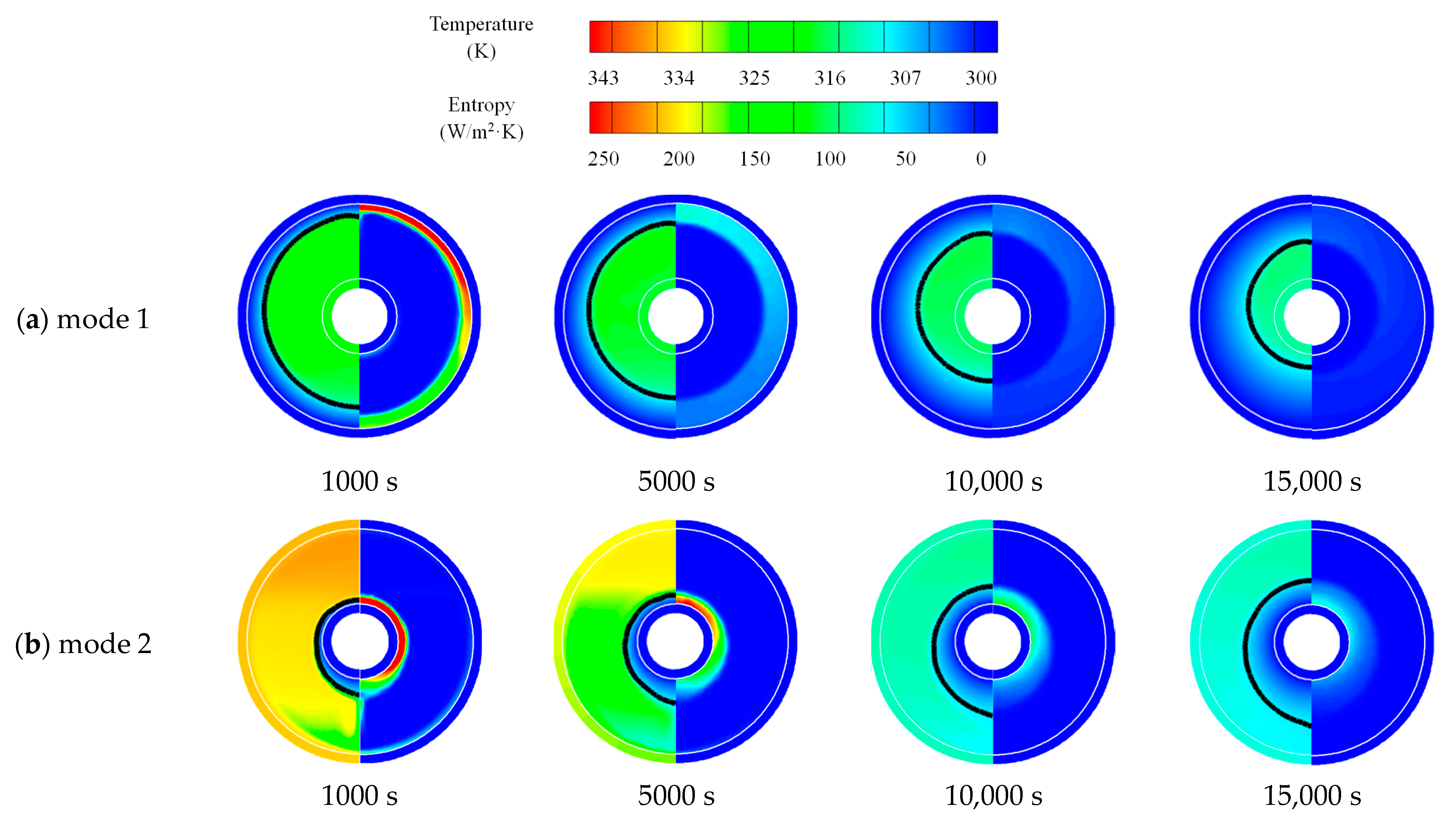
3.1.1. Heat Storage Process
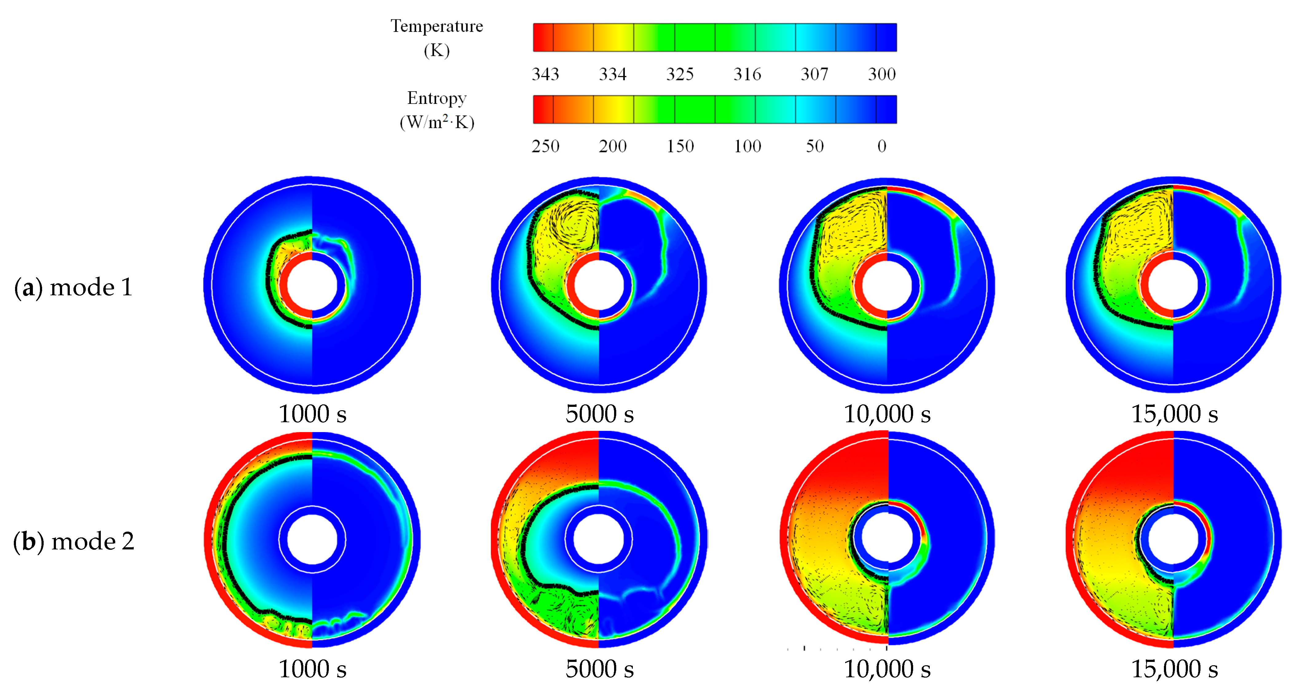
3.1.2. Heat Release Process
3.1.3. Simultaneous Heat Storage and Release Process
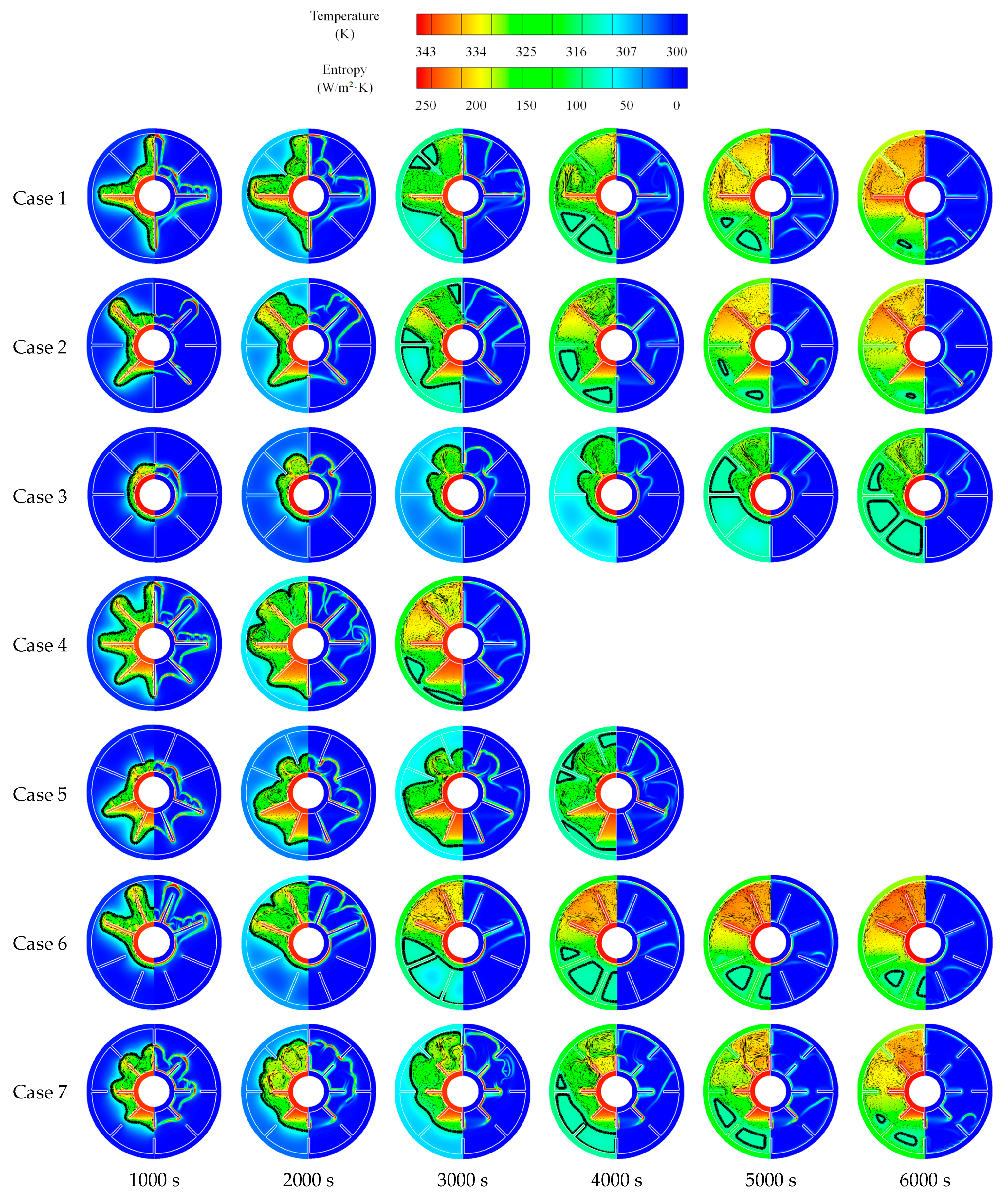
3.2. Comparison of Finned Cases in Different Operating Modes
3.2.1. Heat Storage Process
3.2.2. Heat Release Process
3.2.3. Simultaneous Heat Storage and Release Process
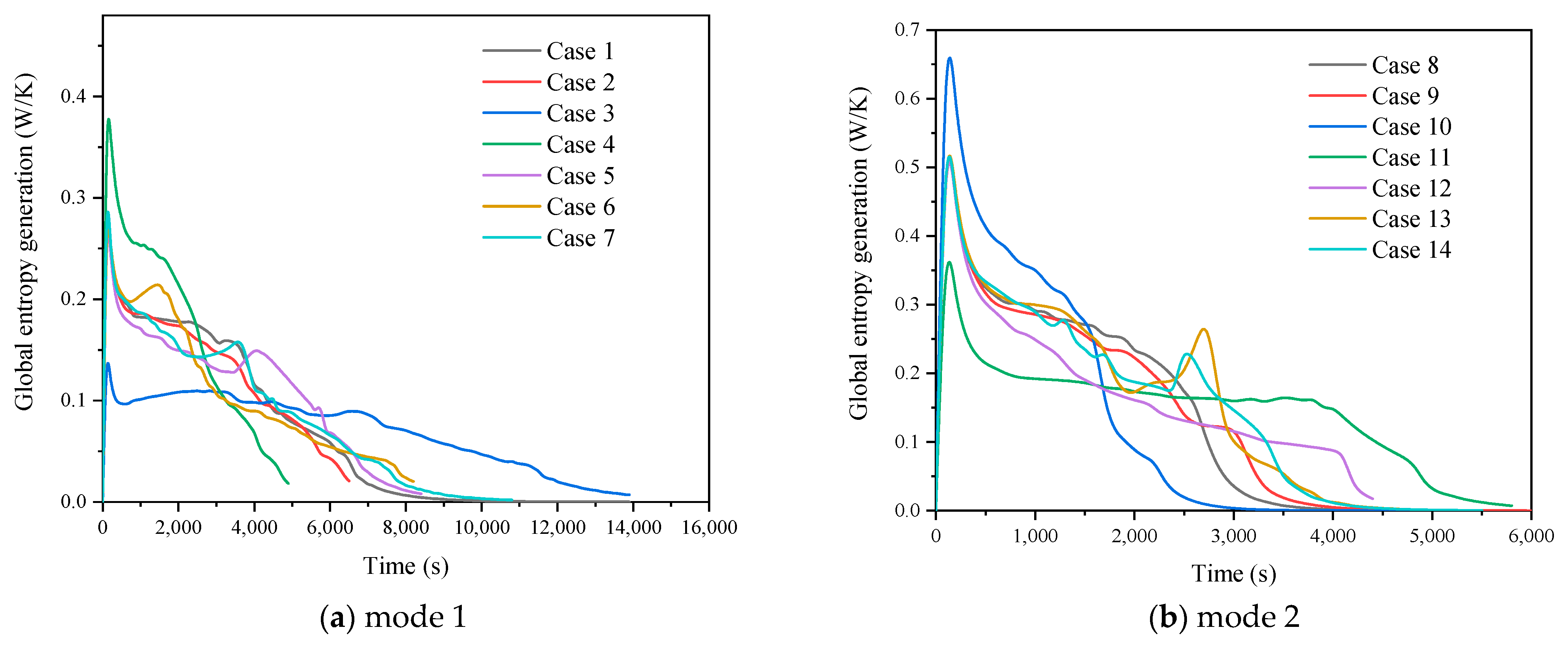
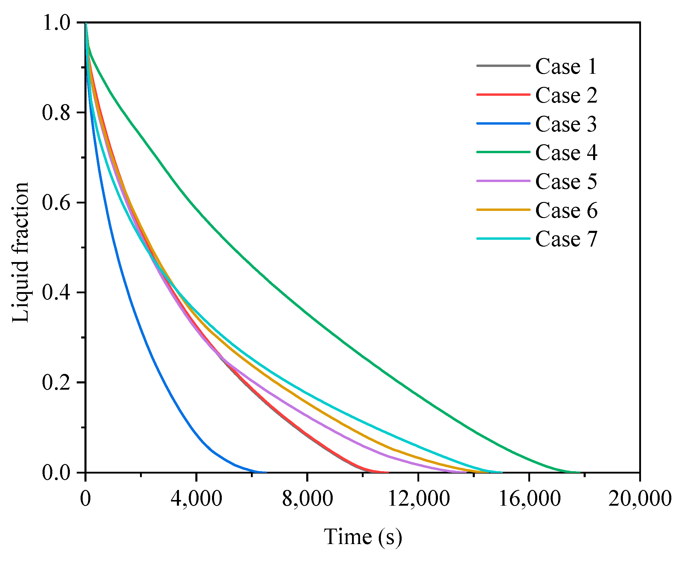
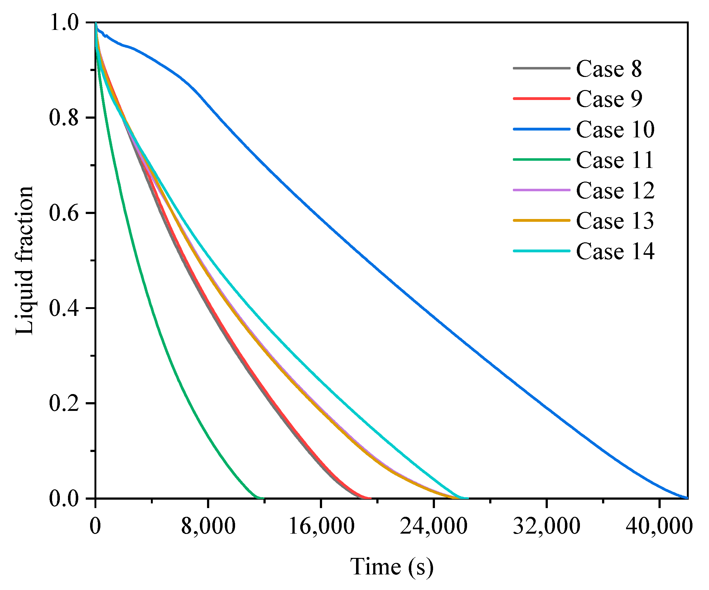
3.3. Comprehensive Evaluation
4. Discussion
- (1)
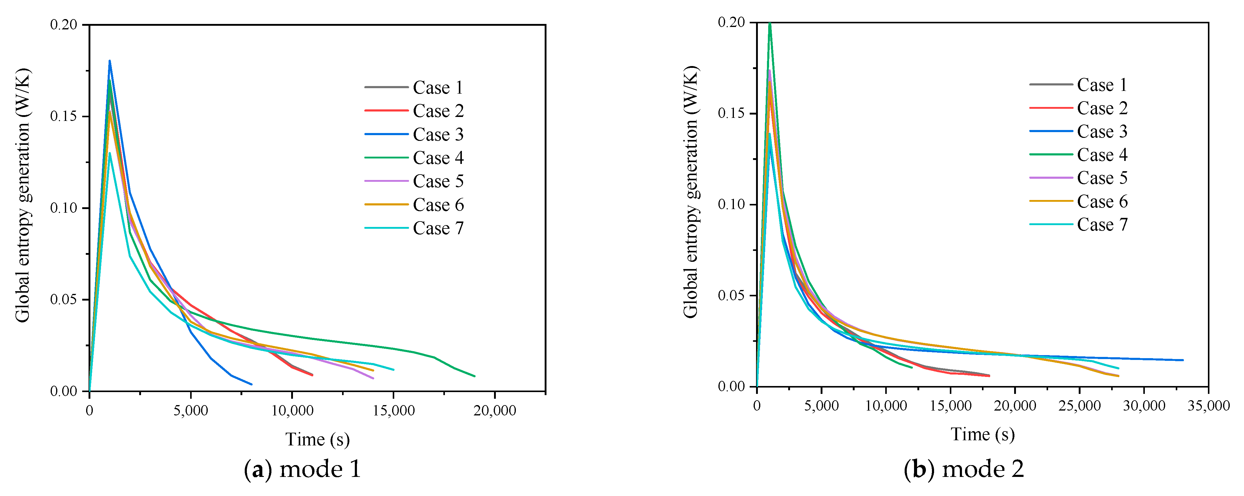
- The composition of entropy showed that the frictional entropy could be ignored compared to the thermal entropy due to the lower velocity gradient in liquid PCM in LHTES systems.
- (2)
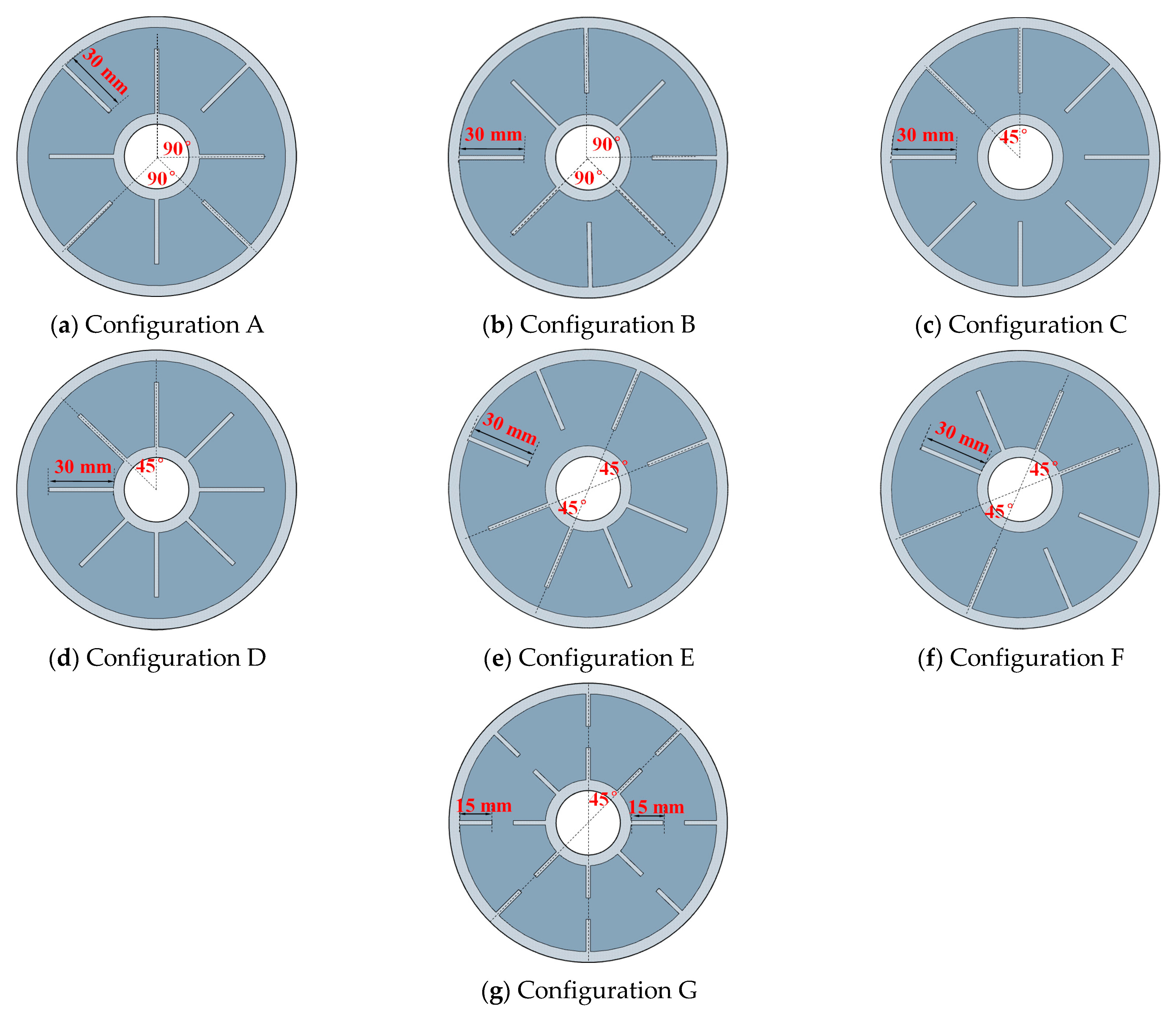
- Inserting fins would increase entropy generation. However, uniformly arranged and longer fins could effectively promote the uniformity of local entropy generation and reduce the of global entropy generation.
- (3)
- Based on the various evaluation parameters, the combination of fin configuration A and operating mode 2 shortens the total time by 66.6% and increases the heat transfer rate by 5.6%, shows the best thermal performance.
Author Contributions
Funding
Institutional Review Board Statement
Informed Consent Statement
Data Availability Statement
Acknowledgments
Conflicts of Interest
References
- Dincer, I. Renewable energy and sustainable development: A crucial review. Renew. Sustain. Energy Rev. 2011, 4, 157–175. [Google Scholar] [CrossRef]
- Kiehbadroudinezhad, M.; Merabet, A.; Abo-Khalil, A.G. Intelligent and Optimized Microgrids for Future Supply Power from Renewable Energy Resources: A Review. Energies 2022, 15, 3359. [Google Scholar] [CrossRef]
- Javadi, F.S.; Metselaar, H.; Ganesan, P. Performance improvement of solar thermal systems integrated with phase change materials (PCM), a review. Sol. Energy 2020, 206, 330–352. [Google Scholar] [CrossRef]
- Dheep, G.R.; Sreekumar, A. Influence of nanomaterials on properties of latent heat solar thermal energy storage materials—A review. Energy Convers. Manag. 2014, 83, 133–148. [Google Scholar] [CrossRef]
- Soares, N.; Costa, J.J.; Gaspar, A.R.; Santos, P. Review of passive PCM latent heat thermal energy storage systems towards buildings’ energy efficiency. Energy Build. 2013, 59, 82–103. [Google Scholar] [CrossRef]
- Gadhave, P.; Pathan, F.; Kore, S. Comprehensive Review of Phase Change Material Based Latent Heat Thermal Energy Storage System. Int. J. Ambient Energy 2021, 1–26. [Google Scholar] [CrossRef]
- Mazhar, A.R.; Shukla, A.; Liu, S. Numerical analysis of rectangular fins in a PCM for low-grade heat harnessing. Int. J. Therm. Sci. 2020, 152, 106306. [Google Scholar] [CrossRef]
- Rk, A.; Ma, A.; Ja, B. Studies on optimum fins number in PCM-based heat sinks. Energy 2019, 171, 1088–1099. [Google Scholar]
- Abdelgaied, M.; Zakaria, Y.; Kabeel, A.E. Improving the tubular solar still performance using square and circular hollow fins with phase change materials. J. Energy Storage 2021, 38, 102564. [Google Scholar] [CrossRef]
- Zhao, C.; Opolot, M.; Liu, M. Numerical study of melting performance enhancement for PCM in an annular enclosure with internal-external fins and metal foams. Int. J. Heat Mass Trans. 2020, 150, 119348. [Google Scholar] [CrossRef]
- Huang, X.; Sun, C.; Chen, Z.; Han, Y. Experimental and numerical studies on melting process of phase change materials (PCMs) embedded in open-cells metal foams. Int. J. Therm. 2021, 170, 107151. [Google Scholar] [CrossRef]
- Nitsas, M.T.; Koronaki, I.P. Performance Analysis of nanoparticles-enhanced PCM: An Experimental Approach. Therm. Sci. Eng. Prog. 2021, 25, 100963. [Google Scholar] [CrossRef]
- Zhang, X.; Niu, J.; Wu, J.Y. Development and characterization of novel and stable silicon nanoparticles-embedded PCM-in-water emulsions for thermal energy storage. Appl. Energy 2019, 238, 1407–1416. [Google Scholar] [CrossRef]
- Sodhi, G.S.; Muthukumar, P. Compound charging and discharging enhancement in multi-PCM system using non-uniform fin distribution. Renew. Energy. 2021, 171, 299–314. [Google Scholar] [CrossRef]
- Mao, Q.; Li, Y. Experimental and numerical investigation on enhancing heat transfer performance of a phase change thermal storage tank. J. Energy Storage 2020, 31, 101725. [Google Scholar] [CrossRef]
- Fan, R.; Zheng, N.; Sun, Z. Evaluation of fin intensified phase change material systems for thermal management of Li-ion battery modules. Int. J. Heat Mass Trans. 2021, 166, 120753. [Google Scholar] [CrossRef]
- Kalapala, L.; Devanuri, J.K. Influence of fin parameters on melting and solidification characteristics of a conical shell and tube latent heat storage unit. J. Energy Resour. Technol. 2021, 144, 14. [Google Scholar] [CrossRef]
- Guo, J.; Liu, Z.; Yang, B. Melting assessment on the angled fin design for a novel latent heat thermal energy storage tube. Renew. Energy 2022, 183, 406–422. [Google Scholar] [CrossRef]
- Mahood, H.B.; Mahdi, M.S.; Monjezi, A.A.; Khadom, A.A.; Campbell, A.N. Numerical investigation on the effect of fin design on the melting of phase change material in a horizontal shell and tube thermal energy storage. J. Energy Storage 2020, 29, 101331. [Google Scholar] [CrossRef]
- Kazemi, M.; Hosseini, M.J.; Ranjbar, A.A. Improvement of Longitudinal Fins Configuration in Latent Heat Storage Systems. Renew. Energy 2017, 116, 447–457. [Google Scholar] [CrossRef]
- Kumar, R.; Verma, P. An experimental and numerical study on effect of longitudinal finned tube eccentric configuration on melting behaviour of lauric acid in a horizontal tube-in-shell storage unit. J. Energy Storage 2020, 30, 101396. [Google Scholar] [CrossRef]
- Yao, S.; Huang, X. Study on solidification performance of PCM by longitudinal triangular fins in a triplex-tube thermal energy storage system. Energy 2021, 227, 120507. [Google Scholar] [CrossRef]
- Abdulateef, A.M.; Mat, S.; Sopian, K. Experimental and computational study of melting phase-change material in a triplex tube heat exchanger with longitudinal/triangular fins. Sol. Energy 2017, 155, 142–153. [Google Scholar] [CrossRef]
- Mat, S.; Al-Abidi, A.A.; Sopian, K.; Sulaiman, M.Y.; Mohammad, A.T. Enhance heat transfer for PCM melting in triplex tube with internal–external fins. Energy Convers. Manag. 2013, 74, 223–236. [Google Scholar] [CrossRef]
- Sharifi, N.; Faghri, A.; Bergman, T.L. Simulation of heat pipe-assisted latent heat thermal energy storage with simultaneous charging and discharging. Int. J. Heat Mass Trans. 2015, 80, 170–179. [Google Scholar] [CrossRef] [Green Version]
- Fang, Y.; Qu, Z.G.; Zhang, J.F.; Xu, H.T.; Qi, G.L. Simultaneous charging and discharging performance for a latent thermal energy storage system with a microencapsulated phase change material. Appl Energy 2020, 275, 115353. [Google Scholar] [CrossRef]
- Mahdi, J.M.; Mohammed, H.I.; Talebizadehsardari, P.; Ghalambaz, M.; Majdi, H.S.; Yaïci, W.; Giddings, D. Simultaneous and consecutive charging and discharging of a PCM-based domestic air heater with metal foam. Appl. Therm. Eng. 2021, 197, 117408. [Google Scholar] [CrossRef]
- Omojaro, P.; Breitkopf, C. Investigating and Modeling of Simultaneous Charging and Discharging of a PCM Heat Exchanger. Energy Procedia 2014, 48, 413–422. [Google Scholar] [CrossRef] [Green Version]
- Joybari, M.M.; Haghighat, F.; Seddegh, S. Heat transfer enhancement of phase change materials by fins under simultaneous charging and discharging. Energ. Convers. Manag. 2017, 152, 136–156. [Google Scholar] [CrossRef]
- Mahdi, J.M.; Lohrasbi, S.; Ganji, D.D. Simultaneous energy storage and recovery in the triplex-tube heat exchanger with PCM, copper fins and Al2O3 nanoparticles. Energ. Convers. Manag. 2019, 180, 949–961. [Google Scholar] [CrossRef]
- Rathod, M.K.; Banerjee, J. Entropy generation assessment of shell and tube latent heat storage unit. Int. J. Exergy 2015, 16, 97–108. [Google Scholar] [CrossRef]
- Nguyen, T.K.; Sheikholeslami, M.; Shehzad, S.A.; Shafee, A.; Alghamdi, M. Solidification entropy generation via FEM through a porous storage unit with applying a magnetic field. Phys. Scr. 2019, 94, 095207. [Google Scholar] [CrossRef]
- Shahsavar, A.; Majidzadeh, A.H.; Mahani, R.B.; Talebizadehsardari, P. Entropy and thermal performance analysis of PCM melting and solidification mechanisms in a wavy channel triplex-tube heat exchanger. Renew. Energy 2021, 165, 52–72. [Google Scholar] [CrossRef]
- Wu, J.; Chen, Q.; Zhang, Y. A novel compensating fins configuration for improving the thermal performance of latent heat thermal energy storage unit. J. Energy Storage 2021, 44, 103328. [Google Scholar] [CrossRef]
- Cao, X.; Yuan, Y.; Xiang, B. Effect of natural convection on melting performance of eccentric horizontal shell and tube latent heat storage unit. Sustain. Cities Soc. 2018, 38, 571–581. [Google Scholar] [CrossRef]
- Nie, C.; Liu, J.; Deng, S. Effect of geometry modification on the thermal response of composite metal foam/phase change material for thermal energy storage. Int. J. Heat Mass Trans. 2021, 165, 120652. [Google Scholar] [CrossRef]
- Mallya, N.; Haussener, S. Buoyancy-driven melting and solidification heat transfer analysis in encapsulated phase change materials. Int. J. Heat Mass Trans. 2021, 164, 120525. [Google Scholar] [CrossRef]
- Oktariani, E.; Tahara, K.; Nakashima, K. Experimental Investigation on the Adsorption Process for Steam Generation Using a Zeolite–Water System. J. Chem. Eng. Jpn. 2012, 45, 355–362. [Google Scholar] [CrossRef]
- Bing, X.; Tahara, K.; Nakashima, K. Numerical simulation for steam generation process in a novel zeolite–water adsorption heat pump. J. Chem. Eng. Jpn. 2012, 45, 408–416. [Google Scholar]
- Guelpa, E.; Sciacovelli, A.; Verda, V. Entropy generation analysis for the design improvement of a latent heat storage system. Energy 2013, 53, 128–138. [Google Scholar] [CrossRef] [Green Version]
- Wu, S.; Huang, Y.; Zhang, C. Role of tree-shaped fins in charging performance of a latent heat storage unit. Int. J. Energy Res. 2020, 44, 4800–4811. [Google Scholar] [CrossRef]
- Wang, Z.; Zhang, H.; Dou, B.; Zhang, G.; Wu, W. Influence of inlet structure on thermal stratification in a heat storage tank with PCMs: CFD and experimental study. Appl. Eng. 2019, 162, 114151. [Google Scholar] [CrossRef]


| Parameter | Unit | Paraffin (RT50) | Aluminum |
|---|---|---|---|
| Specific heat capacity | (kJ/kg·K) | 2.0 | 947 |
| Melting temperature | (°C) | 51 | - |
| Solidification temperature | (°C) | 45 | |
| Latent heat | (kJ/kg) | 168 | - |
| Thermal conductivity | (W/m·K) | 0.2 | 237 |
| Density | (kg/m3) | 800 | 2.7 × 10³ |
| Thermal expansion coefficient | K−1 | 0.0006 | - |
| Dynamic viscosity | (Pa·s) | 0.004 |
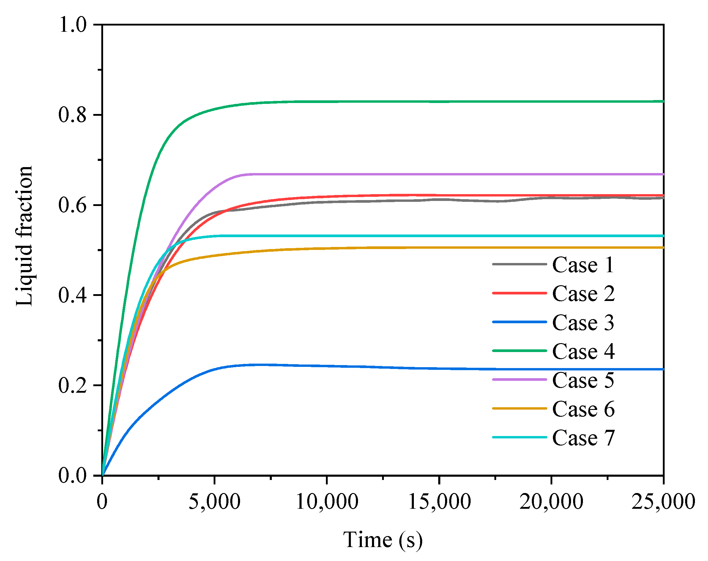
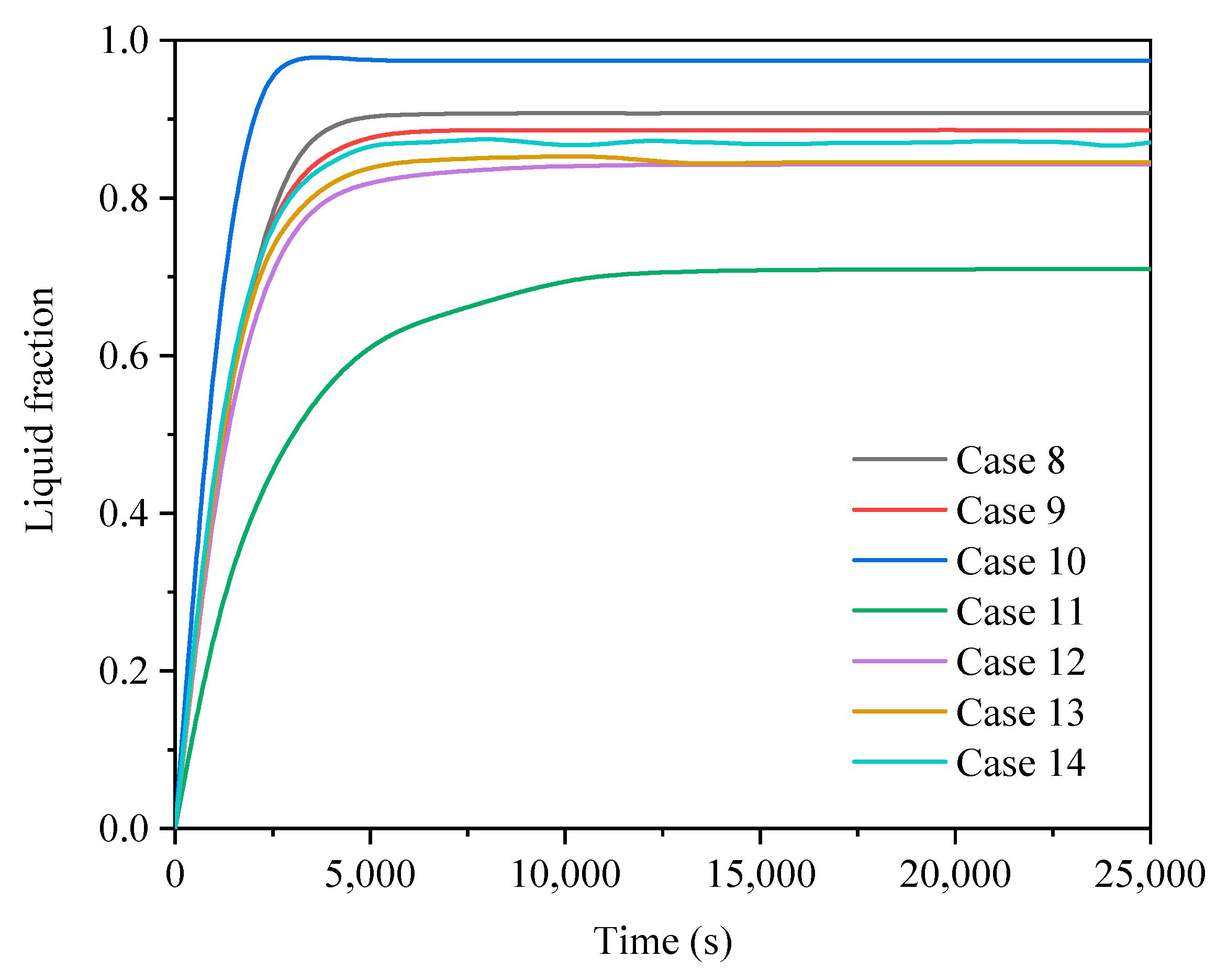
| Case No. | Fin Configurations | Operating Mode |
|---|---|---|
| Case 1 | A | 1 |
| Case 2 | B | 1 |
| Case 3 | C | 1 |
| Case 4 | D | 1 |
| Case 5 | E | 1 |
| Case 6 | F | 1 |
| Case 7 | G | 1 |
| Case 8 | A | 2 |
| Case 9 | B | 2 |
| Case 10 | C | 2 |
| Case 11 | D | 2 |
| Case 12 | E | 2 |
| Case 13 | F | 2 |
| Case 14 | G | 2 |
| Fin Configuration | Operating Mode | Total Time (s) | Liquid Fraction | Heat Transfer Rate (w/m2) |
|---|---|---|---|---|
| Non-finned | 1 | 42,000 | 0.4933 | 127 |
| A | 1 | 17,700 | 0.6178 | 524 |
| B | 1 | 17,900 | 0.6214 | 535 |
| C | 1 | 18,500 | 0.2356 | 288 |
| D | 1 | 22,800 | 0.8297 | 508 |
| E | 1 | 20,300 | 0.6679 | 439 |
| F | 1 | 22,500 | 0.5057 | 398 |
| G | 1 | 23,000 | 0.5317 | 460 |
| Non-finned | 2 | 65,300 | 0.9643 | 583 |
| A | 2 | 22,200 | 0.9077 | 616 |
| B | 2 | 22,800 | 0.8866 | 587 |
| C | 2 | 44,600 | 0.9742 | 331 |
| D | 2 | 16,600 | 0.7098 | 501 |
| E | 2 | 30,700 | 0.8426 | 467 |
| F | 2 | 29,700 | 0.8452 | 476 |
| G | 2 | 29,900 | 0.8705 | 485 |
Publisher’s Note: MDPI stays neutral with regard to jurisdictional claims in published maps and institutional affiliations. |
© 2022 by the authors. Licensee MDPI, Basel, Switzerland. This article is an open access article distributed under the terms and conditions of the Creative Commons Attribution (CC BY) license (https://creativecommons.org/licenses/by/4.0/).
Share and Cite
Wu, J.; Zhang, Y.; Sun, K.; Chen, Q. Heat Transfer Enhancement of Phase Change Material in Triple-Tube Latent Heat Thermal Energy Storage Units: Operating Modes and Fin Configurations. Energies 2022, 15, 5653. https://doi.org/10.3390/en15155653
Wu J, Zhang Y, Sun K, Chen Q. Heat Transfer Enhancement of Phase Change Material in Triple-Tube Latent Heat Thermal Energy Storage Units: Operating Modes and Fin Configurations. Energies. 2022; 15(15):5653. https://doi.org/10.3390/en15155653
Chicago/Turabian StyleWu, Junting, Yingjin Zhang, Kanglong Sun, and Qicheng Chen. 2022. "Heat Transfer Enhancement of Phase Change Material in Triple-Tube Latent Heat Thermal Energy Storage Units: Operating Modes and Fin Configurations" Energies 15, no. 15: 5653. https://doi.org/10.3390/en15155653
APA StyleWu, J., Zhang, Y., Sun, K., & Chen, Q. (2022). Heat Transfer Enhancement of Phase Change Material in Triple-Tube Latent Heat Thermal Energy Storage Units: Operating Modes and Fin Configurations. Energies, 15(15), 5653. https://doi.org/10.3390/en15155653