Article

Numerical and Experimental Investigation on Safety of Downhole Solid–Liquid Separator for Natural Gas Hydrate Exploitation

1
Cooperative Innovation Center of Unconventional Oil and Gas, Yangtze University (Ministry of Education & Hubei Province), Wuhan 430100, China
2
School of Environmental and Chemical Engineering, Shanghai University, Shanghai 200444, China
3
College of Architecture & Environment, Sichuan University, Chengdu 610065, China
*
Authors to whom correspondence should be addressed.
Energies 2022, 15(15), 5649; https://doi.org/10.3390/en15155649
Submission received: 28 June 2022 / Revised: 27 July 2022 / Accepted: 2 August 2022 / Published: 4 August 2022

Abstract

:
Deep water shallow natural gas hydrate (NGH) is a kind of clean energy and has entered the commercial exploitation stage. However, it produces a lot of seabed sediment in the process of large-scale mining, which not only easily causes undersea natural hazards, but also leads to pipeline equipment blockage and high energy consumption in the mining process. A downhole solid–liquid separator can effectively separate natural gas hydrate from sand and backfill sand in situ, which can effectively solve this problem. In this paper, the safety of a downhole solid–liquid separator desander under torsion conditions is determined by a test method. A numerical simulation method was used to simulate the tension and pressure of the downhole solid–liquid separator, and a modal simulation analysis and erosion analysis of the downhole solid–liquid separator were carried out. The experiments showed that the downhole solid–liquid separator could withstand 30 KN/m of torque, and a numerical simulation analysis showed that it could withstand 30 MPa of pressure and 50 KN of tension. The results show that the maximum stress is 116.56 MPa, and the maximum allowable stress is 235 MPa. The modal analysis showed that the downhole solid–liquid separator produces resonance at a frequency of about 93 Hz, resulting in large deformation, which should be avoided as far as possible. Through the erosion analysis, the life of the downhole solid–liquid separator was determined to be about 2.3 years. Numerical simulation and experimental results show that the designed downhole solid–liquid separator for natural gas hydrate can ensure safety.

1. Introduction

Natural gas hydrate (NGH) has the characteristics of wide distribution, a large number of resources, and high energy density [1,2]. The carbon stored in NGH is about twice the total carbon content of the known conventional energy in the world [3]. Therefore, the efficient exploitation and utilization of NGH is necessary. The lithology of the NGH reservoir in the South China Sea is mainly argillaceous silty fine-grained sediments [4,5]. It has the characteristics of a shallower burial depth, lower permeability, worse cementation, and no dense caprock [6,7]. Therefore, NGH mining in the South China Sea is more difficult. For the relatively shallow burial of fine-grained natural gas hydrate-bearing sediments in the South China Sea, the solid–fluid mining scheme is currently adopted [8,9]. At present, the solid-state fluidized mining technology faces the problem of a large amount of sand production, and the separation of argillaceous silt has become one of the core issues of solid-state fluidized mining [10,11]. Large amounts of sand transported to the ground are difficult to process quickly and efficiently, and increase economic costs [12,13]. The downhole solid–liquid separator for natural gas hydrate exploitation can in situ backfill the sand in the mixed liquid without conveying it to the ground, which can effectively solve this problem [14]. Therefore, the development and application of a new downhole solid–liquid separator for natural gas hydrate is imminent.
Before the large-scale production and application of the solid–liquid separator for natural gas hydrate exploitation, it is necessary to evaluate its safety to prevent its failure in the working process and avoid economic losses, which is one of the indispensable links. Most of the current studies are based on the separation efficiency study of the cyclone separator [15,16,17,18,19], and there are few studies on the safety of the separator. The safety research of other tools can be used for reference. One scholar has carried out in-depth, special research on magnetic particle inspection [20]. At present, there are two important problems to be solved in the process of magnetic particle inspection: the lack of theoretical analysis on the formation of the crack indications, and quantitative characterization methods to determine the crack indications. Experimental results revealed that the optimal magnetic particle concentration was 3–4 mL/L, and, under this condition, the contrast between the crack indications and the background of the crack images was obvious. At present, the research on safety performance mostly focuses on several other downhole tools. It is necessary to study downhole tools based on actual working conditions such as pressure to ensure the safety of the tools in downhole pressure. Another scholar studied the force of downhole tools [21]. He verified and tested the performance of downhole sealing rings in a pressure environment. The objectives of this experimental study are to develop testing protocols to investigate the performance of common elastomeric seals that are used in a liner hanger seal assembly. The pressure cycling results showed that elastomers’ energization plays a critical role in maintaining their seal integrity. The downhole environment is complex. Fluid–solid coupling between various liquids and downhole tools produces different frequencies of vibration. Vibration and shock are one of the important reasons for the failure of downhole tools. One scholar studied the vibration of downhole tools [2], starting from the initial configuration of a drilling tool and considering the contact impact of the drilling tool and the borehole wall; the dynamic excitation of the guide mechanism; and the drilling pressure, torque, rotational speed, gravity, buoyancy, and drilling fluid damping. The dynamic characteristics of the inherent frequency and dynamic stress of the bottom hole assembly were calculated and analyzed, and a risk assessment method based on the quantitative vibration intensity was established. Erosion is an important factor affecting the service life of oil and gas equipment. The erosion in the pipeline has been studied [22]; in the study, fracturing pipeline erosion was evaluated under the action of multiphase flow through both experimental study and computational fluid dynamics (CFD) simulation. The flow characteristic of particles in a fracturing pipe can be described as the comprehensive effects of centrifugal force, turbulent diffusion, and mainstream and secondary flow carrying effect. At present, there is still a lack of research on the comprehensive evaluation of the safety of the solid–liquid separator.
Aiming at the problem of large sand production in the solid fluidization mining process of natural gas hydrate [23,24], in this paper, a new solid–liquid separator for a natural gas hydrate exploitation-axial flow annular in situ cyclone desander is proposed. Sand remover application scenarios are shown in Figure 1. At present, most of the papers focus on separation efficiency. In this paper, the safety of the downhole solid–liquid separator is analyzed innovatively. The new downhole solid–liquid separator has the characteristics of high separation efficiency, and the product was manufactured for the first time for the experiment. Since the results of the numerical simulation and actual experiment are quite different, the safety performance of the downhole solid–liquid separator is comprehensively evaluated through the combination of numerical simulation and experiment, including flaw detection experiment, numerical simulation of tension and compression, torsion experiment, modal analysis, and numerical simulation of erosion, which lays a solid foundation for the large-scale application of the downhole solid-liquid separator in the future.

2. The Method and Process Experiment and Simulation

2.1. Reasons for Failure of a Downhole Solid–Liquid Separator for NGH
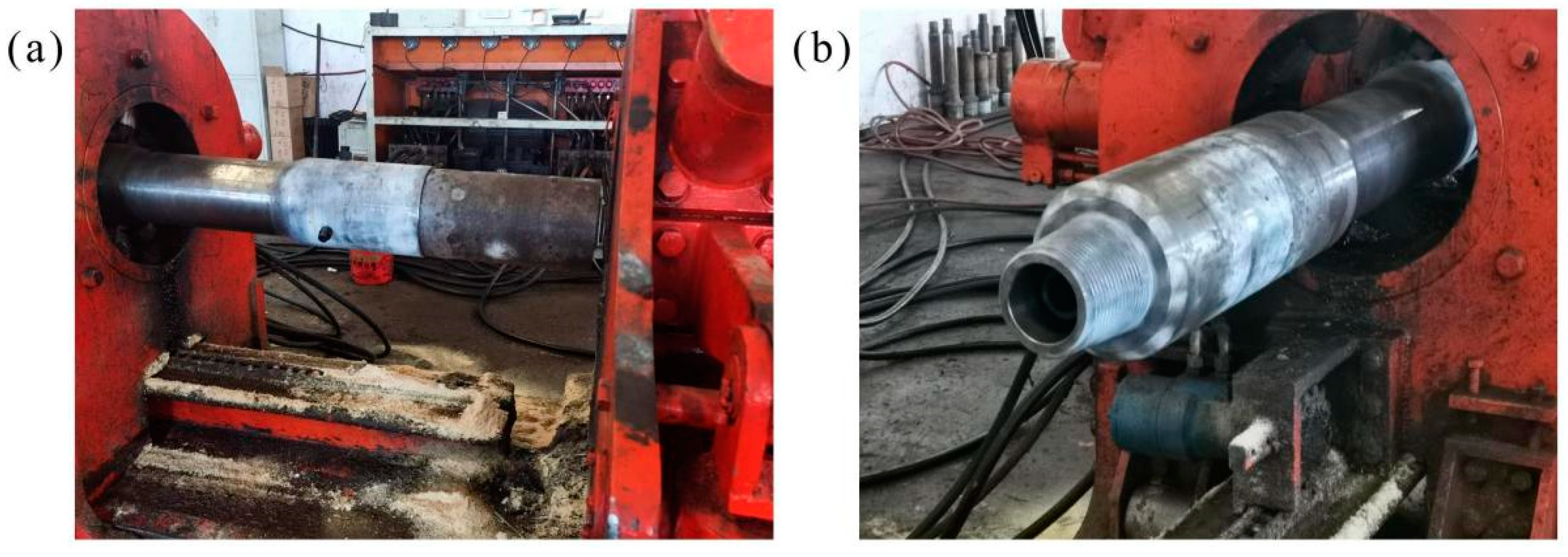
The working principle of the downhole solid–liquid separator for NGH is that drilling fluids carrying gas hydrates and sediments are transported underground to the sea level drilling platform, through the annular space around the inner pipe [25,26], and the mixed liquid of the underground natural gas hydrate and sand is transported from the ground to the sea through the middle pipe [27,28]. When passing through the inner pipe of the downhole solid–liquid separator, the gas hydrate and sand are separated [29,30]. The specific process is shown in Figure 1. The role of drilling fluid is to break the natural gas hydrate solid through a downhole jet, and then carry the broken gas hydrate particles back to the ground. The downhole environment is complex, and the force of the downhole solid–liquid separator is also complex, which is mainly affected by the tension, torque, and vibration transmitted by other downhole tools and strings [31]. The mixed liquid with a high underground sediment concentration causes erosion to the inner tube [32]. The material of the downhole solid–liquid separator shell is 42CrMo, which belongs to plastic material, and plastic deformation occurs under tension. The downhole solid-liquid separator also bears the torque and vibration transmitted from other tubing strings and downhole tools, resulting in torsional deformation and resonance, and resonance can also cause deformation, thus making the downhole solid-liquid separator failure. Finally, the mixed liquid in the inner tube passes through the spiral blade in the downhole solid–liquid separator due to the centrifugal force, which collides with the inner tube wall and causes erosion. The above-mentioned cases may cause the failure of the downhole solid–liquid separator, resulting in economic losses.

2.2. Twisting Test

To check whether the downhole solid–liquid separator was damaged before and after the test, magnetic particle flaw detection was used to test each component. Firstly, the penetrant was sprayed on the surface of the downhole solid–liquid separator. After spraying, the imaging agent was evenly sprayed on the surface of the downhole solid–liquid separator at a certain distance until the penetration was completed. The magnetic powder was uniformly dispersed on the surface of the downhole solid–liquid separator shell. Meanwhile, the CDX-3 multi-purpose magnetic particle flaw detector (Figure 2a) was used for detection, as shown in Figure 2b. The magnetic particle flaw detector generates a current to display by cutting a magnetic induction line through defects. The instrument displays at 0 A, indicating no current generation and no pointer swing, and no abnormal aggregation of magnetic particles on the surface of the downhole solid–liquid separator shell is observed. After the downhole solid–liquid separator test is completed, repeat the above steps to test the downhole solid–liquid separator again to see if there is any damage. The test results show that the downhole solid–liquid separator is not damaged.

2.3. Numerical Examples and Analysis

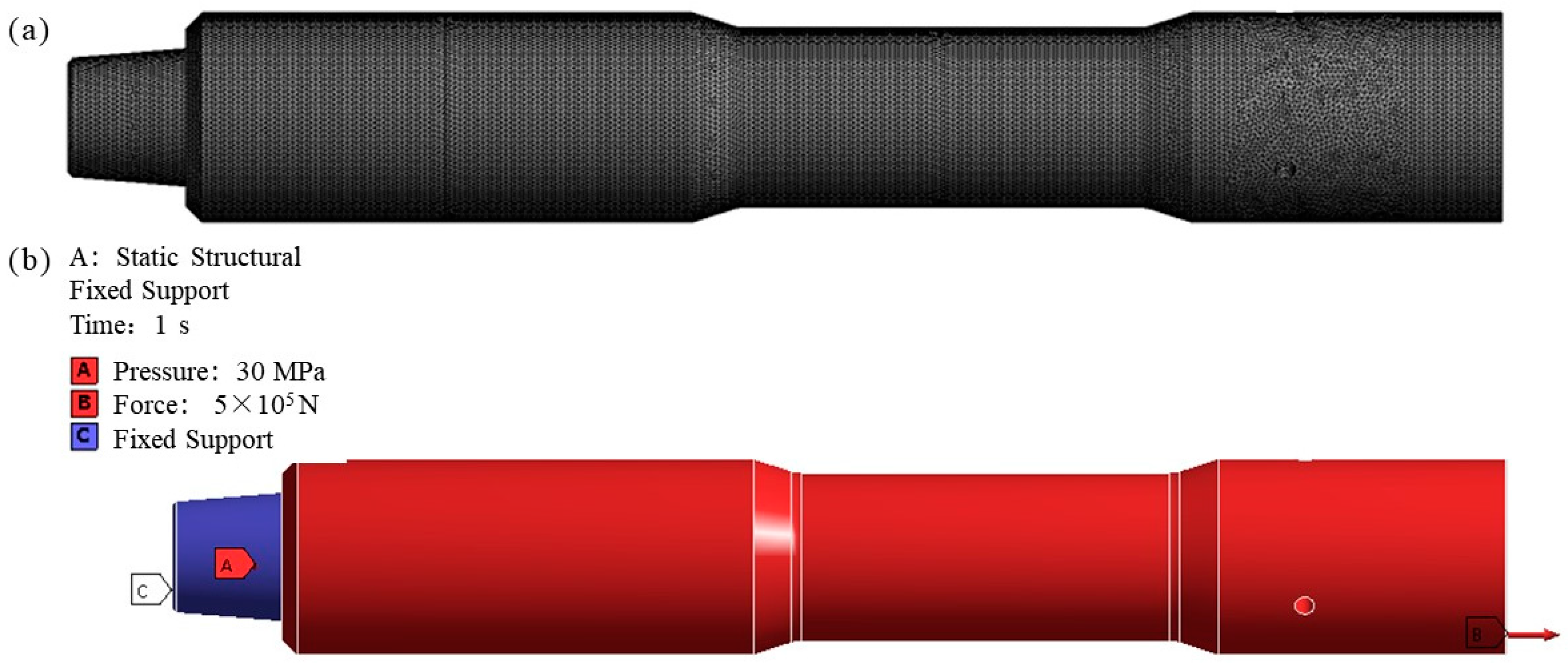
2.3.1. Tension and Compression Simulation Analysis

After importing the established solid model into ANSYS, the analysis using numerical simulation is carried out. Some initial conditions used are the shell of the downhole solid–liquid separator made of 42CrMo material, whose elastic modulus is 2.12 × 10¹¹ Pa, Poisson’s ratio is 0.3 and density is 7850 kg/m3. The specific materials of other parts of the downhole solid–liquid separator are shown in Table 1.
The main force of the downhole solid–liquid separator in the normal working environment is the tensile force that is transmitted by the downhole tool. According to the normal stress formula:
δ = F N A
Formula: δ is the stress value, unit pa; FN is a positive stress, and the unit is N; A is the cross-sectional area, in m2.
The strength condition of the downhole solid–liquid separator is that the maximum tensile stress cannot exceed the allowable stress of 42CrMo material 930 MPa:
δ max = F N max A [ δ ]
According to Hooke’s law, in the elastic range, the normal stress is proportional to the linear strain, so there are:
Δ l = F N l E A
Formula: E is the elastic modulus; EA is tensile stiffness, l is the total length of the downhole solid–liquid separator, and ∆l is the elongation after tension.
Since the cross-sectional area of the downhole solid–liquid separator shell is not always consistent, the maximum stress and maximum elongation of the downhole solid–liquid separator shell cannot be accurately calculated by the formula. Because the deformation is small and the maximum stress is difficult to measure, numerical simulation is a good solution. In the above formulas, the local sensitivities of FN and A in Equation (1) are 1 and −1, respectively; the local sensitivities of FNmax and A in Equation (2) are 1 and −1; the local sensitivities of FN and l in Equation (3) are 1; and the local sensitivities of E and A are −1. The casing of the downhole solid–liquid separator is threaded to the upper and lower downhole tools. The downhole solid–liquid separator is meshed by the Mesh in Workbench 18.0 software, and the tetrahedron-dominated unit division is adopted. In order to ensure the calculation accuracy, the unit size is a 5 mm grid, and the number of grids is 102,536, as shown in Figure 3a. The working condition of the downhole solid–liquid separator is the coiled tubing with a suspension strength of >2 inches, so the thread on the upper side of the downhole solid–liquid separator is fixed, and the pull force on the lower side of the shell of the downhole solid–liquid separator is about 5 × 10⁵ N. The formation pressure on both the inner and outer surfaces is 30 MPa. Boundary conditions of the downhole solid–liquid separator are shown in Figure 3b.

2.3.2. Modal Simulation Analysis

The damped method was used for the modal analysis and the first six natural frequencies were calculated. In practice, the influence of low-order mode is usually greater than that of high-order mode, so the first 1–6 orders of the vibration frequency of the downhole solid–liquid separator are taken as the analysis object when conducting a modal analysis of the downhole solid–liquid separator.
Modal is the inherent vibration characteristics of the structure. The modal parameter information can be obtained by a theoretical analysis, and the calculation process is called a modal analysis. Its essence is to solve the eigenvalues and eigenvectors of the structural characteristic equation. For the free vibration system without damping, its motion equation is as follows:
[ M ] { X ¨ } + [ K ] { X } = 0
Among them, { X ¨ } , { X } are the acceleration and displacement vector of each degree of freedom; [M] and [K] are the mass matrix and stiffness matrix, respectively.
Assuming that the free vibration of a multi-degree-of-freedom vibration system is a harmonic motion, then:
{ x } = { x }   sin ( ω t + θ )  
where { X } is the shape of the system, which is related to the amplitude and independent of time; ω and θ are the vibration mode frequency and phase angle, respectively. The above two equations are combined and converted to obtain:
det { [ K ] ω 2 [ M ] } = 0  
If Equation (6) holds, the free vibration with limited amplitude can be obtained, which is the frequency equation. If in the whole system, the corresponding number of degrees of freedom is N, then according to the above calculation, we can obtain N roots sorted from small to large and the frequency vector {ω}. ωi is the natural frequency of the corresponding first mode:
ω = { ω 1 , ω 2 , ω 3 , , ω i } T
Through the modal analysis of the structure, the accurate analysis of the natural frequency and basic vibration mode of the structure is beneficial to the analysis of the dynamic characteristics of the structure. For the downhole solid–liquid separator, its structure, operation, position, and excitation are special. The correct study of the structural characteristics of the downhole solid–liquid separator is of great significance to determine whether it can operate safely [33,34].

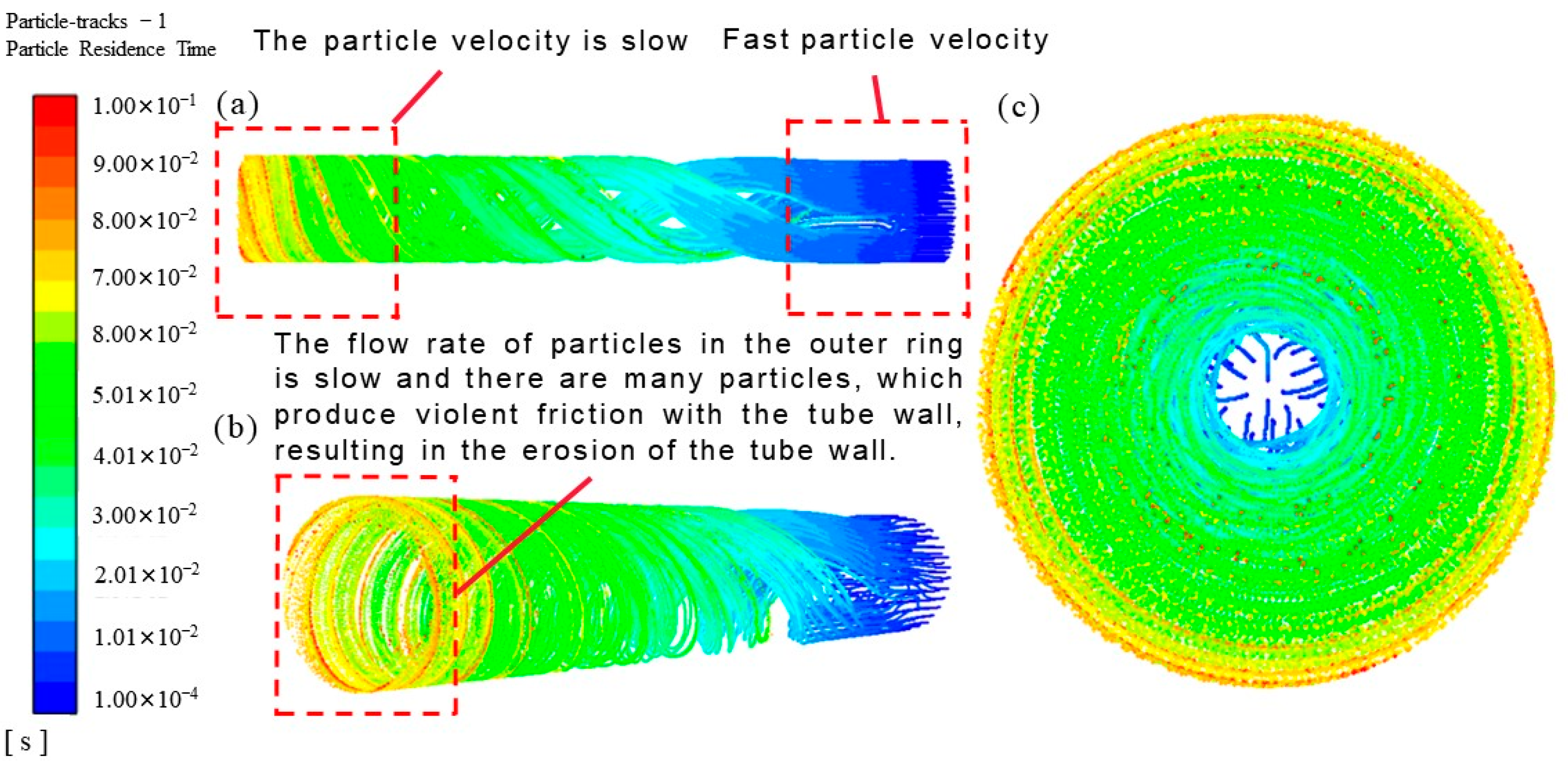
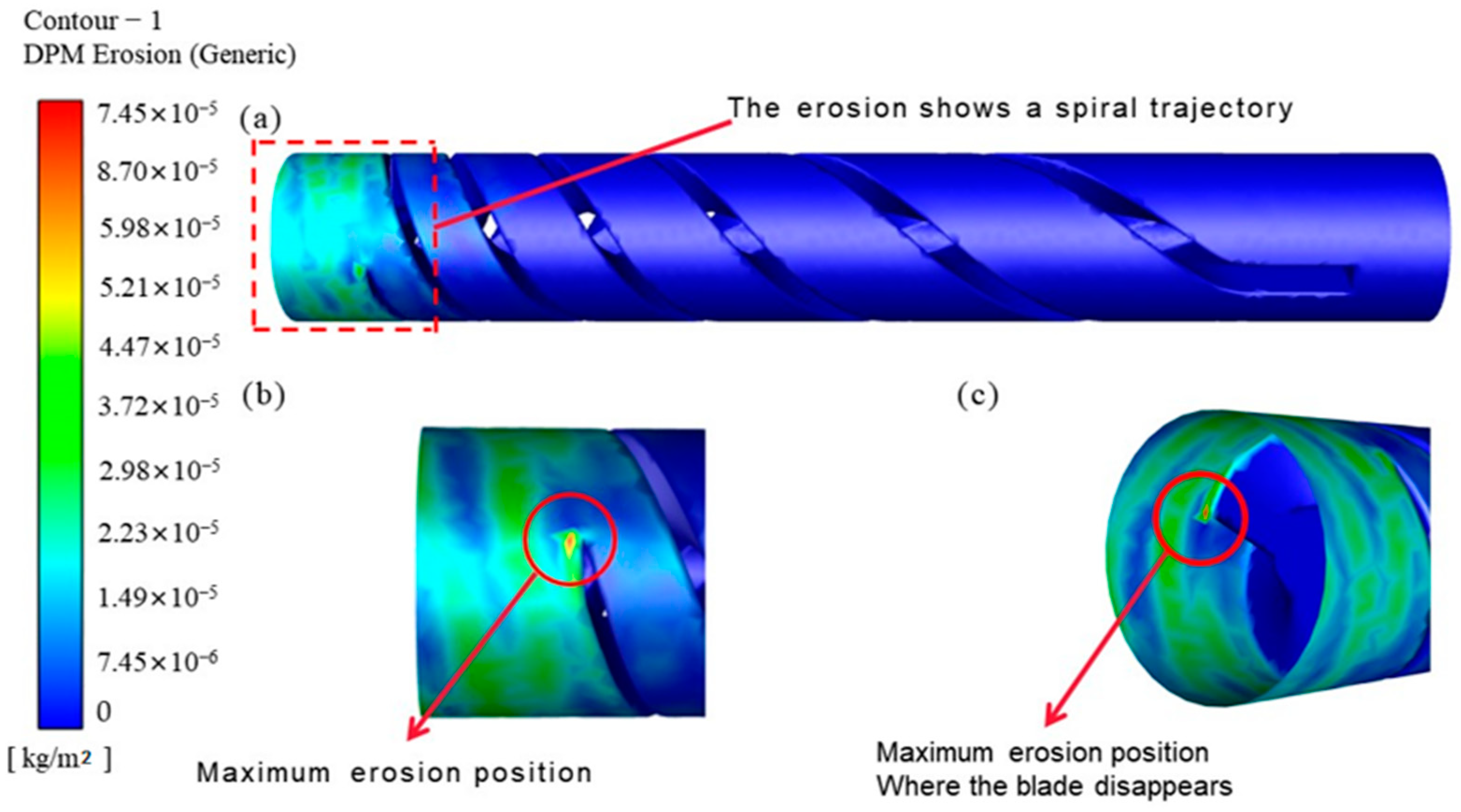
2.3.3. Erosion Analysis

The downhole solid–liquid separator is mainly used to separate the sand in NGH. After the sand containing NGH passes through the downhole solid–liquid separator, the centrifugal force of the downhole solid–liquid separator causes the sand particles to move towards the pipe wall, which increases the sand content of NGH near the pipe wall and discharge from the sand outlet. Therefore, NGH with high sand content causes relatively large erosion to the inner wall of the downhole solid–liquid separator, resulting in damage to the downhole solid–liquid separator. Therefore, it is of great practical significance to the erosion analysis of the downhole solid–liquid separators.
The solver was set as follows: The solver selected the pressure-based solver, the time attribute was defined as transient (instantaneous flow), and the speed attribute was defined as absolute (absolute speed). The Discrete Phase Model (DPM Model) was selected as the computing model, and the Realizable K-Epsilon Model was selected as the turbulence model. The default parameters were kept unchanged. The density of the wall material was 7830 kg/m3. To simplify the calculation of liquid density, the density of water was adopted, and the density of sand was 2500 kg/m3. Both outlets were set as free flow outlets, which were directly connected with the pipe string to simulate the actual working state of the downhole solid–liquid separator. According to the working characteristics of the downhole solid–liquid separator, the SIMPLEC algorithm and QUICK difference scheme are used to solve the flow field in the calculation process of Fluent.

3. Results and Discussion

3.1. Torsional Performance Evaluation

The downhole solid–liquid separator shell was mounted on the testing machine and each component was assembled on the testing machine, as shown in Figure 4. The main parts of the tension, pressure, bending and torsion testing machine were measured, and the pressure was used for simple calculation. The bending moment that was used in the test was 30 KN/m, the push rod diameter of the bending and torsion testing machine was 70 mm, and the bending moment was 1500 mm.
The torque experiment of the downhole solid–liquid separator was carried out, and the torque experimental data were the added pressure of 3 MPa. The torque was calculated by the following formula:
Pressure used:
P = M π D 2 4 × L = 3 MPa  
L is the radius of the testing machine, L = 1.5 m; P is the test pressure; M is the torque on the specimen, M = 30 KN/m; and D is the diameter of the piston push rod, D = 0.07 m.
The formula conversion shows that the cyclone separator can withstand a torque of 30 KN/m, and the strength of 42CrMo is 930 MPa. The rated torque of the tool can be obtained by the following calculation formula:
W = π ( D 4 d 4 ) 32 D 2 = 2.7 MPa  
D is the outer diameter of the downhole solid–liquid separator shell, D = 985 mm; d is the inner diameter of the downhole solid–liquid separator shell, d = 635 mm. The experimental pressure data of 3 MPa are converted into a torque of 30 KN/m by Formula (13), which is slightly larger than the designed rated torque of 2.7 MPa. No damage was found by the flaw detection experiment, which proves the safety of torsional strength. In the above formulas, the values of D and d were determined. In Formula (8), the local sensitivity of M is 1, and the local sensitivity of L is −1.

3.2. Evaluation of Tension and Compression Performance

According to the numerical simulation analysis of tension and pressure, the maximum stress of the downhole solid–liquid separator was 116.56 MPa and the maximum strain was about 0.001 mm under the pressure of 50 KN and 30 MPa, which met the requirements.
A finite element analysis was conducted according to the boundary conditions of the shell of the downhole solid–liquid separator to obtain the results of the strain and stress of the downhole solid–liquid separator, as shown in Figure 5. The simulation analysis showed that the maximum stress of the downhole solid–liquid separator was 116.56 MPa, located at the first thread of the upper thread, which was caused by the maximum stress on the first thread, the position of the maximum deformation also occurs in the first ring thread. Here, it was about 0.001 mm. The yield stress of 15CrMo material was 235 MPa and the safety factor was 2.02, which met the safety standard.

3.3. Modal Performance Evaluation

The order and frequency results of the modal analysis are shown in Table 2. Figure 6 shows the vibration displacement from the first order to the sixth order of the downhole solid–liquid separator.
As can be seen from Figure 6, in the six vibration modes of the downhole solid–liquid separator, the deformation is large at the first frequency and the second frequency. According to the modal analysis, the amplitude of the downhole solid–liquid separator is about 4.9 mm, which is the largest at a 93.00 Hz frequency. Therefore, vibration of the pipe string at a 93.00 Hz frequency should be avoided in practical applications to prevent damage caused by excessive deformation of the downhole solid–liquid separator.

3.4. Erosion Performance Evaluation

When liquid flows through spiral blade of inner tube of downhole solid-liquid separator with uniform particles, because the particles are subjected to centrifugal force, the particles gradually approach the inner tube wall and collide with the inner tube wall. A small part of the fluid flows out of the sediment outlet with a large number of particles, and the trajectory of the fluid changes from straight forward to spiral forward when passing through the spiral blade, so the erosion of the particles on the inner tube also presents a spiral shape. The particle movement track is shown in Figure 7. It can be seen from the figure that the particles close to the fast velocity collide with the pipe wall after passing through the downhole solid–liquid separator, and the velocity gradually decreases, resulting in the erosion of the pipe wall.
The erosion cloud diagram is shown in Figure 8a. The maximum erosion rate is 7.45 × 10⁻⁵ kg/m2, and the location is shown in Figure 8b,c. The maximum erosion occurs at the point where the last blade is in contact with the pipe wall. At this point, the rectification and separation effect of the downhole solid–liquid separator is the strongest, so the erosion rate is also the largest. After the fluid passes through the downhole solid–liquid separator, the streamline becomes chaotic, and the erosion rate decreases accordingly.
The maximum erosion rate ER = 7.45 × 10⁻⁵ kg·m−2·s−1 is proposed to represent the average erosion rate E in the bottom area, but because the erosion rate changes with time, the correction coefficient k is needed. It can be seen from Figure 8. It can be seen from the diagram that the maximum erosion rate is ten times different from the minimum erosion rate. The ratio of the minimum to the maximum erosion rate in the erosion area is 0.1, and k = 0.1 after comprehensive consideration.
The average erosion rate E in the erosion area is:
E = k E R    
Particle erosion spiral blade and inner tube contact are not good, causing vibration and aggravating wear. The erosion depth is calculated according to the mass loss of the wall material. The erosion of the erosion model mainly occurs at the back of the inner tube. The mass loss MR of the slotted casing is calculated as follows:
M R = E S
Formula S for the erosion area, m2, according to the estimate S = 0.0088 m2.
According to the volume formula, after the mass loss is transformed into the volume loss, the erosion depth can be calculated as:
L = V R S = M R ρ b S
In the formula: L is the erosion depth, mm; VR is volume loss, m3; ρb is the density of the sleeve material, kg/m3; the material used in the inner tube is TiN; and the density is 5430 kg/m3.
The service life T of the downhole solid–liquid separator is:
T = D / L = ρ b D / ( k E R )  
where D is the allowable erosion depth of the downhole solid–liquid separator inner tube, D = 0.1 mm, and the inner tube coating is 0.1 mm thick. When the erosion exceeds 0.1 mm, the tube wall has serious electrochemical corrosion with natural gas hydrate, and the corrosion rate increases sharply. The calculated T is about 7.289 × 10⁷ s, converted to 2.3 years of service life. In the above formula, the value of k is determined. The local sensitivity of ER in Formula (10) is 0.1; the local sensitivities of E and S in Formula (11) are 1; the local sensitivities of ρb and S in Formula (12) are −1; the local sensitivities of MR are 1; the local sensitivities of ρb and D in Formula (13) are 1; and the local sensitivity of ER is −1.

4. Conclusions

In this paper, experimental and numerical simulations are used to analyze the safety of a new type of downhole solid–liquid separator from different angles. Previous studies are mostly based on separation efficiency. The innovation of this paper lies in:
(1)
The axial annulus in situ desander was not damaged by the magnetic particle detection test before and after the test. By observing the distribution of magnetic particles on the axial annulus in situ desander shell surface and the oscillation of the magnetic particle detector pointer, it was proved that the axial annulus in situ desander was not damaged.
(2)
Through the numerical simulation of tension and pressure, it is shown that the maximum stress of the shell of the downhole solid–liquid separator is 116.56 MPa and the maximum deformation is about 0.001 mm under the combined action of 30 MPa bottom hole pressure and 5 × 10⁵ N tension, which is not more than the allowable stress of the material. It is proven that the downhole solid–liquid separator is safe.
(3)
Through the modal analysis of the downhole solid–liquid separator, the first six modes are obtained. In the practical engineering application, the six frequencies of 92.96 Hz, 93.00 Hz, 481.09 Hz, 481.17 Hz, 623.39 Hz, and 1019.20 Hz should be avoided to prevent damage to the downhole solid–liquid separator that is caused by resonance.
(4)
The torsional experiment of the downhole solid–liquid separator is to estimate the torque that it can withstand by using the relevant formula, and then the relevant experiments are carried out to prove that it can be used normally under the normal condition of 30 KN/m torque, and there is no damage after the pre-test and post-test.
(5)
Through the erosion numerical analysis of the downhole solid–liquid separator, the maximum erosion rate under normal conditions is obtained by numerical simulation, and the erosion area is measured. The service life is estimated to be 2.3 years by the formula.
Through the formula derivation, numerical simulation, and experiment of different angles, the safety of the downhole solid–liquid separator is preliminarily proven from multiple angles. This is the first time that the product has been manufactured and an experiment carried out, which lays the foundation for its large-scale commercial application in the future.

Author Contributions

Conceptualization, J.W. and X.Y.; methodology, Q.N. and S.Z.; software, Q.N.; validation, Q.N.; formal analysis, Q.N.; investigation, Y.H.; resources, Y.H.; data curation, Q.N.; writing—original draft preparation, Q.N.; writing—review and editing, X.Y. and J.W.; visualization, Q.N.; supervision, Y.H.; project administration, X.Y. and J.W.; funding acquisition, J.W. All authors have read and agreed to the published version of the manuscript.

Funding

This research was funded by Open Foundation of Cooperative Innovation Center of Unconventional Oil and Gas, Yangtze University (Ministry of Education & Hubei Province), No. UOG2022-28, National Natural Science Foundation of China No. 52000071 and National Natural Science Foundation of China No. 52100135.

Conflicts of Interest

The authors declare no conflict of interest.

Nomenclature

NGHnatural gas hydrate[K]stiffness matrixLerosion depth
δstress valuePtest pressureρbdensity
FNpositive stressMtorqueTservice life
EAtensile stiffnessDouter diameterDallowable erosion depth
ltotal lengthdinner diameterkratio
lelongation after tensionERmaximum erosion rateSerosion area
[M]mass matrixωvibration mode frequency

References

  1. Vedachalam, N.; Srinivasalu, S.; Rajendran, G.; Ramadass, G.A.; Atmanand, M.A. Review of unconventional hydrocarbon resources in major energy consuming countries and efforts in realizing natural gas hydrates as a future source of energy. J. Nat. Gas Sci. Eng. 2015, 26, 163–175. [Google Scholar] [CrossRef]
  2. Wang, W.C.; Wang, X.Y.; Li, Y.X.; Liu, S.; Yao, S.P.; Song, G.C. Study on the characteristics of natural gas hydrate crystal structures during decomposition process. Fuel 2020, 271, 117537. [Google Scholar] [CrossRef]
  3. Chong, Z.R.; Yang, S.H.B.; Babu, P.; Linga, P.; Li, X.S. Review of natural gas hydrates as an energy resource: Prospects and challenges. Appl. Energy 2016, 162, 1633–1652. [Google Scholar] [CrossRef]
  4. Fang, Y.X.; Wei, J.G.; Lu, H.L.; Liang, J.Q.; Lu, J.A.; Fu, J.; Cao, J. Chemical and structural characteristics of gas hydrates from the Haima cold seeps in the Qiongdongnan Basin of the South China Sea. J. Asian Earth Sci. 2019, 182, 103924. [Google Scholar] [CrossRef]
  5. Wu, Z.R.; Liu, W.G.; Zheng, J.A.; Li, Y.H. Effect of methane hydrate dissociation and reformation on the permeability of clayey sediments. Appl. Energy 2020, 261, 114479. [Google Scholar] [CrossRef]
  6. Ma, S.H.; Zheng, J.N.; Tang, D.W.; Lv, X.; Li, Q.P.; Yang, M.J. Experimental investigation on the decomposition characteristics of natural gas hydrates in South China Sea sediments by a micro-differential scanning calorimeter. Appl. Energy 2019, 254, 113653. [Google Scholar] [CrossRef]
  7. Wei, J.G.; Fang, Y.X.; Lu, H.L.; Lu, H.F.; Lu, J.A.; Liang, J.Q.; Yang, S.X. Distribution and characteristics of natural gas hydrates in the Shenhu Sea Area, South China Sea. Mar. Petrol. Geol. 2018, 98, 622–628. [Google Scholar] [CrossRef]
  8. Tang, Y.; Sun, P.; Wang, G.R.; Fu, B.W.; Yao, J.X. Rock-breaking mechanism and efficiency of straight-swirling mixed nozzle for the nondiagenetic natural gas hydrate in deep-sea shallow. Energy Sci. Eng. 2020, 8, 3740–3752. [Google Scholar] [CrossRef]
  9. Wang, L.Z.; Wang, G.R.; Mao, L.J.; Fu, Q.; Zhong, L. Experimental research on the breaking effect of natural gas hydrate sediment for water jet and engineering applications. J. Pet. Sci. Eng. 2020, 184, 106553. [Google Scholar] [CrossRef]
  10. Kuang, Y.M.; Yang, L.; Li, Q.P.; Lv, X.; Li, Y.P.; Yu, B.; Leng, S.D.; Song, Y.C.; Zhao, J.F. Physical characteristic analysis of unconsolidated sediments containing gas hydrate recovered from the Shenhu Area of the South China sea. J. Pet. Sci. Eng. 2019, 181, 106173. [Google Scholar] [CrossRef]
  11. Zhou, S.W.; Li, Q.P.; Lv, X.; Fu, Q.; Zhu, J.L. Key issues in development of offshore natural gas hydrate. Front. Energy 2020, 14, 433–442. [Google Scholar] [CrossRef]
  12. Qiu, S.Z.; Wang, G.R. Effects of Reservoir Parameters on Separation Behaviors of the Spiral Separator for Purifying Natural Gas Hydrate. Energies 2020, 13, 5346. [Google Scholar] [CrossRef]
  13. Qiu, S.Z.; Wang, G.R.; Zhou, S.W.; Liu, Q.Y.; Zhong, L.; Wang, L.Z. The downhole hydrocyclone separator for purifying natural gas hydrate:structure design, optimization, and performance. Sep. Sci. Technol. 2020, 55, 564–574. [Google Scholar] [CrossRef]
  14. Chang, Y.L.; Ti, W.Q.; Wang, H.L.; Zhou, S.W.; Huang, Y.; Li, J.P.; Wang, G.R.; Fu, Q.; Lin, H.T.; Wu, J.W. Hydrocyclone used for in-situ sand removal of natural gas-hydrate in the subsea. Fuel 2021, 285, 119075. [Google Scholar] [CrossRef]
  15. Karagoz, I.; Avci, A.; Surmen, A.; Sendogan, O. Design and performance evaluation of a new cyclone separator. J. Aerosol Sci. 2013, 59, 57–64. [Google Scholar] [CrossRef]
  16. Misiulia, D.; Antonyuk, S.; Andersson, A.G.; Lundstrom, T.S. High-efficiency industrial cyclone separator: A CFD study. Powder Technol. 2020, 364, 943–953. [Google Scholar] [CrossRef]
  17. Wang, S.Y.; Li, H.L.; Wang, R.C.; Wang, X.; Tian, R.C.; Sun, Q.J. Effect of the inlet angle on the performance of a cyclone separator using CFD-DEM. Adv. Powder Technol. 2019, 30, 227–239. [Google Scholar] [CrossRef]
  18. Xiong, Z.Y.; Ji, Z.L.; Wu, X.L. Development of a cyclone separator with high efficiency and low pressure drop in axial inlet cyclones. Powder Technol. 2014, 253, 644–649. [Google Scholar] [CrossRef]
  19. Zhang, P.; Chen, G.H.; Duan, J.H.; Wang, W.W. Experimental evaluation of separation performance of fine particles of circulatory circumfluent cyclone separator system. Sep. Purif. Technol. 2019, 210, 231–235. [Google Scholar] [CrossRef]
  20. Li, L.; Yang, Y.; Cai, X.; Kang, Y.H. Investigation on the Formation Mechanism of Crack Indications and the Influences of Related Parameters in Magnetic Particle Inspection. Appl. Sci. 2020, 10, 6805. [Google Scholar] [CrossRef]
  21. Ahmed, S.; Salehi, S.; Ezeakacha, C.; Teodoriu, C. Experimental investigation of elastomers in downhole seal elements: Implications for safety. Polym. Test. 2019, 76, 350–364. [Google Scholar] [CrossRef]
  22. Zhang, J.X.; Kang, J.; Fan, J.C.; Gao, J.C. Study on erosion wear of fracturing pipeline under the action of multiphase flow in oil & gas industry. J. Nat. Gas Sci. Eng. 2016, 32, 334–346. [Google Scholar]
  23. Tang, Y.; Yao, J.X.; He, Y.; Sun, P.; Jin, X. Study on pressure-controlled sliding sleeve of jet breaking for natural gas hydrate mining based on throttle pressure drop principle. Energy Sci. Eng. 2020, 8, 1422–1437. [Google Scholar] [CrossRef]
  24. Tang, Y.; Zhao, P.; Li, X.S.; Fang, X.Y.; Yang, P. Numerical Simulation and Experimental Test of the Sliding Core Dynamics of a Pressure Controlled Jet Crushing Tool for Natural Gas Hydrate Exploitation. Processes 2022, 10, 1033. [Google Scholar] [CrossRef]
  25. Wang, Q.B.; Wang, R.; Sun, J.X.; Sun, J.S.; Lu, C.; Lv, K.; Wang, J.T.; Wang, J.L.; Yang, J.; Qu, Y.Z. Effect of Drilling Fluid Invasion on Natural Gas Hydrate Near-Well Reservoirs Drilling in a Horizontal Well. Energies 2021, 14, 7075. [Google Scholar] [CrossRef]
  26. Zhao, X.; Qiu, Z.; Wang, M.; Xu, J.; Huang, W. Experimental investigation of the effect of drilling fluid on wellbore stability in shallow unconsolidated formations in deep water. J. Pet. Sci. Eng. 2019, 175, 595–603. [Google Scholar] [CrossRef]
  27. Saasen, A.; Ding, S.X.; Amundsen, P.A.; Tellefsen, K. The Shielding Effect of Drilling Fluids on Measurement While Drilling Tool Downhole Compasses-The Effect of Drilling Fluid Composition, Contaminants, and Rheology. J. Energy Resour. Technol. 2016, 138, 052907. [Google Scholar] [CrossRef]
  28. Zheng, M.M.; Liu, T.L.; Jiang, G.S.; Wei, M.; Huo, Y.X.; Liu, L. Large-scale and high-similarity experimental study of the effect of drilling fluid penetration on physical properties of gas hydrate-bearing sediments in the Gulf of Mexico. J. Pet. Sci. Eng. 2020, 187, 106832. [Google Scholar] [CrossRef]
  29. Kou, J.; Li, Z.Y. Numerical Simulation of New Axial Flow Gas-Liquid Separator. Processes 2022, 10, 64. [Google Scholar] [CrossRef]
  30. Wang, Y.G. Analysis for spiral vortex and effect of profile of nozzle and swirler on performance of supersonic separator. Chem. Eng. Process.-Process Intensif. 2020, 147, 107676. [Google Scholar] [CrossRef]
  31. Liu, Y.; Ma, T.S.; Chen, P.; Yang, C. Method and apparatus for monitoring of downhole dynamic drag and torque of drill-string in horizontal wells. J. Pet. Sci. Eng. 2018, 164, 320–332. [Google Scholar] [CrossRef]
  32. Parvaz, F.; Hosseini, S.H.; Elsayed, K.; Ahmadi, G. Numerical investigation of effects of inner cone on flow field, performance and erosion rate of cyclone separators. Sep. Purif. Technol. 2018, 201, 223–237. [Google Scholar] [CrossRef]
  33. Aloisio, A.; Di Pasquale, A.; Alaggio, R.; Fragiacomo, M. Assessment of Seismic Retrofitting Interventions of a Masonry Palace Using Operational Modal Analysis. Int. J. Archit. Herit. 2022, 16, 692–704. [Google Scholar] [CrossRef]
  34. Dziedziech, K.; Mendrok, K.; Kurowski, P.; Barszcz, T. Multi-Variant Modal Analysis Approach for Large Industrial Machine. Energies 2022, 15, 1871. [Google Scholar] [CrossRef]
Figure 1. Application scenario of downhole solid–liquid separator.
Energies 15 05649 g001
Figure 2. Torsion test flaw detection process and equipment. (a) Flaw detection process; (b) flaw detection equipment.
Energies 15 05649 g002
Figure 3. Meshing and boundary conditions of downhole solid–liquid separator. (a) Meshing; (b) boundary conditions.
Energies 15 05649 g003
Figure 4. Torsion test equipment. (a) Specimen and lower tooling; (b) specimen and upper tooling.
Energies 15 05649 g004
Figure 5. Deformation and stress diagram of downhole solid–liquid separator. (a) Deformation distribution; (b) stress distribution.
Energies 15 05649 g005
Figure 6. Schematic diagram of deformation of various vibration modes of the downhole solid–liquid separator. (a) First order mode; (b) second order mode; (c) third order mode; (d) fourth order mode; (e) fifth order mode; (f) sixth order mode.
Energies 15 05649 g006
Figure 7. Particle track of downhole solid–liquid separator. (a,b) Side view; (c) front view.
Energies 15 05649 g007
Figure 8. Pipe wall of axial downhole solid–liquid separator. (a) Overall erosion cloud diagram; (b,c) local erosion cloud diagram.
Energies 15 05649 g008
Table 1. Material list of parts of the downhole solid–liquid separator.
PartMaterials
Desander adapter42CrMo
Desander conversion connector internals40CrNiMoA
Desander housing42CrMo
Desander sand discharge nozzle40CrNiMoA
Desander female internal connector40CrNiMoA
Desander outlet conduit40CrNiMoA
Helical blade 40CrNiMoA
Desander inner pipe40CrNiMoA
Desander male inner connector40CrNiMoA
Table 2. The first six natural frequencies of the downhole solid–liquid separator.
DegreeFrequency/HzShape Change/mm
First order92.964.8721
Second order93.004.8725
Third order481.094.8614
Fourth order481.174.8609
Fifth order623.394.5748
Sixth order1019.203.5501
Publisher’s Note: MDPI stays neutral with regard to jurisdictional claims in published maps and institutional affiliations.

