3.1. Model Description
Figure 3 shows the diagram of the nozzle and the location of the diffuser in more detail. The shock wave configuration under study is the two attached shocks that appear at the diffuser inlet. Brass electrodes are mounted in the walls of the nozzle and the diffuser over the entire width of the flow.
When the ionized gas moves in the channel in a transverse magnetic field, an electromotive force (EMF) ε = uBh arises (where u is the flow velocity, B is the magnetic induction vector, and h is the distance between the electrodes), separating charges in opposite directions. When a magnetically induced current or a current from an external source is closed through the electrodes, the ponderomotive force FL will act on the flow. The speed of the oncoming flow will change, while the position of the attached shocks will also change.
The obtained Schlieren pattern of the flow in the absence of external influences is shown in
Figure 4a. This is the initial position of the attached shocks.
Figure 4b shows the layout of the shocks and the parameters that were used to characterize the degree of change in their position. This is the distance
Xc from the entrance to the diffuser to the point of intersection of the shocks, the angle α at which the shocks meet, and the angle of inclination of the shock to the diffuser wall
φ. Here the initial experimental values of these parameters are shown, 2
α = 42°,
Xc = 42 mm,
φ = 15.5°. The main experimental problem for MHD flow control in this case is to change the angle of inclination of the attached shocks, both into increase and decrease.
3.2. Organization of MHD Impact
A preliminary study of the current-voltage characteristics showed that due to the large near-electrode and near-wall layers in this configuration of the diffuser, it is impossible to close the magnetically induced current. Therefore, studies are carried out both with the imposition of external magnetic and external electric fields. This approach has some advantages, since it provides wider opportunities for research. In particular, there is the opportunity to investigate not only the braking, but also the accelerating effect of the pondermotive force. This is not possible when only the magnetically induced current is closed, or when the ponderomotive force works only for braking.
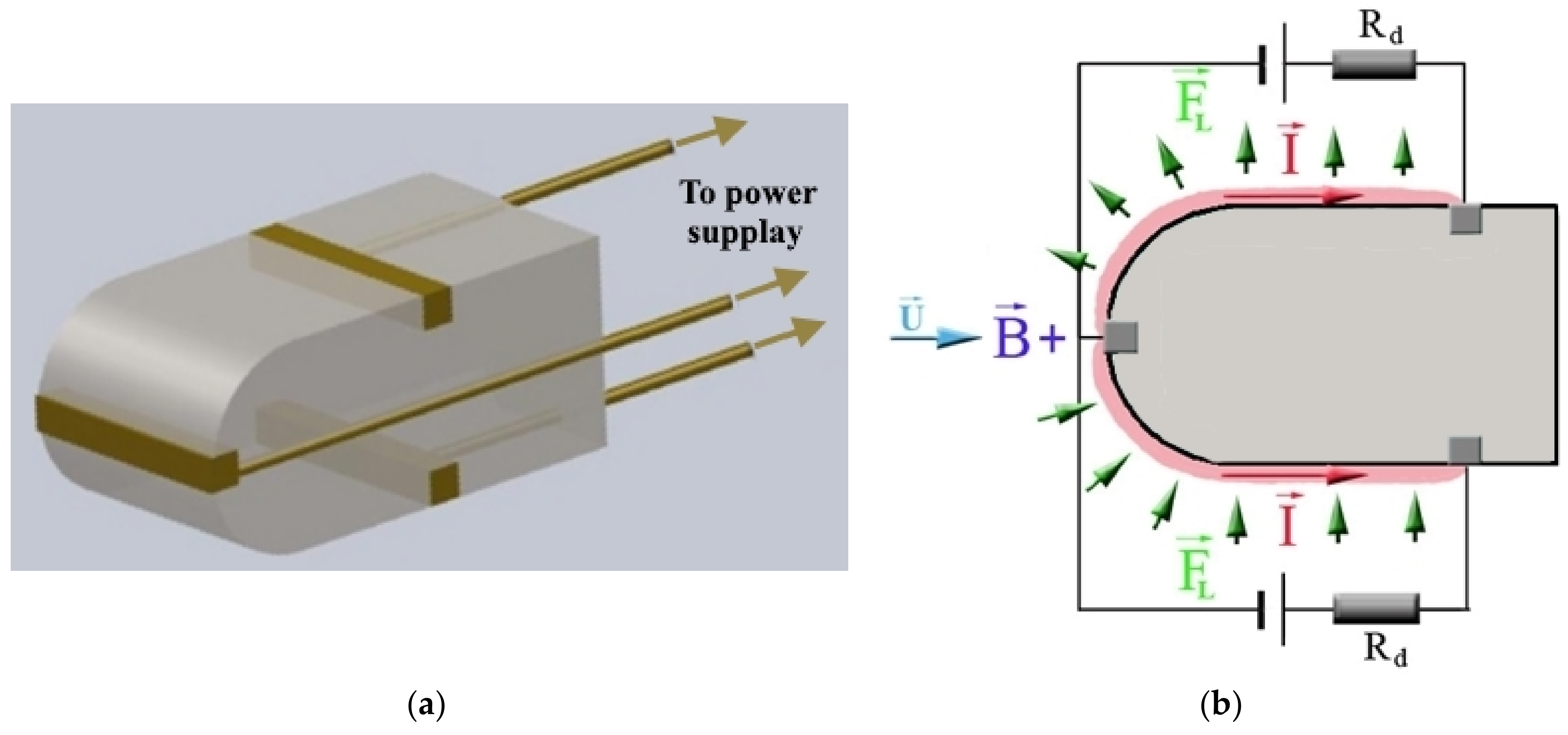
An external electric field is created by applying an external voltage to the electrodes from specially created LC circuits. The current is closed through a circuit consisting of an interelectrode plasma gap with resistance
Reff and a load resistance
RL. The current configuration can be changed by connecting different pairs of electrodes. The gas discharge current closes without keys at the moment when ionized gas enters the interelectrode gap. The external voltage connection diagram and the direction of action of the ponderomotive force in the case of a transverse circuit of the current, when the upper electrode is the cathode, are shown in
Figure 5a. With such a circuit, the current from the external voltage coincides in direction with the magnetically induced current, and the ponderomotive force acts to decelerate the flow. If the current is directed in the opposite direction, as shown in the following
Figure 5b, the ponderomotive force works to accelerate the flow. Similarly, it is possible to connect any number of electrodes in different areas of the diffuser. It is possible to circuit both the transverse and longitudinal current. The numbering of electrodes adopted in the work is also indicated in the figures.
The equivalent circuit for connecting magnetically induced EMF
ε and external voltage V for such a circuit is shown in
Figure 5c. Here the LC circuit is represented as an external source of EMF, supplying a voltage
V to the electrode circuit. It is connected in series with an MHD generator with
ε =
uBh and internal resistance
Reff, which is the sum of the volume resistance of the plasma gap between the electrodes. The total value of the EMF and the applied voltage is partly applied to the load resistance
RL, and partly to the internal resistance of the interelectrode gap
Reff. Ohm’s law in this case is:
where the voltage drops across the internal resistance:
voltage drop across the load:
k is the load factor:
The “+” sign before
V means the MHD brake, the “−” sign means the MHD accelerator. The main factors affecting the flow structure under the action of external fields are the work of the ponderomotive force, which either slows down or accelerates the supersonic flow depending on the direction of the current; Joule heating of the gas in the external and magnetically induced electric fields, which always leads to deceleration of the supersonic flow; and the influence of the near-wall layer. The Stewart parameter is chosen as a parameter characterizing the force effect. It is the ratio of the work of the ponderomotive force over the length of the interaction zone
L, to the doubled kinetic energy of the flow at the inlet (
j is the current density,
ρ0 and
u0 are the initial density and velocity of the gas):
The ratio of the Joule heat released during the interaction to the doubled kinetic energy of the flow was taken as the thermal parameter of the impact:
These parameters are used in evaluating the effectiveness of external influences. In this case, the gas dynamic parameters are taken from the calculation, and the main electro-physical parameters are determined in the experiment; for this, the current-voltage characteristics of the discharge were taken. The potential difference between the electrodes VAC was measured, as well as voltage on the load resistance to determine the current in the circuit. The most effective action is considered to be the one that, at the lowest force parameter St and thermal parameter N, leads to a stronger change in the position of the attached shocks.
3.3. Characteristics of the Ionized Gas in the Impact Area
The current-voltage characteristic for the input pair of electrodes, obtained in the absence of a magnetic field by varying the external voltage, is shown in
Figure 6a (blue squares). The near-electrode drop is about Δ
V = 50 V. The current-voltage characteristic when a magnetic field of 1.3 T is applied is shown here by red circles. It turns out that the addition of magnetically induced EMF does not lead to an increase in current.
To determine the conductivity of the gas in the core of the flow, the potential distribution in the interelectrode gap was measured. Point electrodes were mounted in the side walls of the diffuser in the region of the inlet pair of electrodes. The change in the potential distribution, when currents of different magnitudes flow through the plasma, is shown in
Figure 6b. The break in the distribution shows near-electrode potential drops. As can be seen, for different values of the applied external voltage, the experimental distribution of the potential in the core of the flow is described by almost parallel straight lines. From this it is clear that when the current in the circuit changes, the voltage drop in the core of the flow practically does not change, which indicates an increase in the conductivity of the core of the flux as the electric current increases. The magnitude of the near-electrode voltage drop Δ
V is the sum of the voltage drop at the cathode ΔV
C. The voltage drops at the anode Δ
VA is about 50–60 V, which is comparable to the magnitude of the magnetically induced EMF. All distributions are characterized by the dependence Δ
VA ≤ Δ
VC, and there is a clear tendency to reduce the total near-electrode drop Δ
V = Δ
VA + Δ
VC with an increasing current. When a magnetic field is applied, the near-electrode voltage drops increase.
The graph in
Figure 7a compares the effective plasma conductivity (squares). It shows the averaged conductivity over the entire interelectrode gap, with the conductivity in the flow core without near-electrode regions (circles) in the absence of a magnetic field (blue color) and during MHD interaction (red color). It can be seen that the conductivity increases with an increasing current due to the development of nonequilibrium ionization. The conductivity in the core of the flow is higher than the effective one. The imposition of a magnetic field reduces both the effective conductivity and the conductivity of the flux core. This is due to the imperfection of the electrodes and the Hall effect, as well as due to the increase in the near-wall boundary layer during MHD interaction.
Electron temperature and density were also measured in the experiment. To do this, a series of spectral measurements were carried out using an Ocean Optics 2000 spectrograph made by Ocean Optics Company in USA. The temperature was measured from the decay of continuous radiation in the ultraviolet region of the spectrum. Due to the peculiarities of the location of the energy levels of inert gases, the intensity of continuous luminescence in the ultraviolet region can be described by the exponential formula:
where
ne and
Te are the electron density and temperature, C is some constant, ν is the radiation frequency, and
hP and
kB are the Planck and Boltzmann constants, respectively. If we take the logarithm of this expression, we see that the ratio logarithm of the intensities at two frequencies,
ν1 and
ν2 in the ultraviolet region will characterize the electron temperature:
In this case, the electron concentration will be determined by the expression:
As a luminosity standard for determining the spectral sensitivity of the spectrograph and the absolute values of the intensity, we used the luminescence of a plug of shock-compressed gas in a shock tube under known and well-studied flow regimes. The experimentally measured values of temperature and electron density are shown in
Figure 7b. It can be seen that the temperature and electron density increase with the increasing current due to the selective heating of electrons. This increases the conductivity of the gas and, consequently, the intensity of the MHD effect on the flow.
3.4. Characteristics of the Ionized Gas in the Impact Area
The first series of experiments was carried out to study the influence of the magnetic field on the change in the shock wave configuration.
Figure 8 shows the Schlieren flow patterns when the transverse current in the braking mode was closed through all pairs of electrodes located in the diffuser. The length of the impact zone
L is marked in the figure. When a small magnetic field is applied a shift of the shocks is visible, due to a decrease in the Mach number of the flow. Compared with the picture in the absence of fields, the angle of inclination of the shocks relative to the wall of diffuser has increased. The point of intersection of the shocks has shifted from
Xc = 42 mm to 35 mm. Qualitatively, this picture can be called a weak MHD interaction. The position of the shocks has changed, but their reflection from each other remains regular.
When a magnetic field of 1.3 T is applied, the flow pattern changes significantly. The regular reflection of the shocks becomes Mach reflection; we see the formation of a direct shock of MHD deceleration, which transforms the supersonic flow into the subsonic one. This is a typical case of strong MHD interaction. However, the picture is complicated by the development of the near-wall layer; its thickness increased in comparison with the weak MHD interaction.
Figure 8b plots the distance to the point of intersection with the jumps, depending on the magnitude of the magnetic induction. In analyzing the shock wave configuration, depending on the degree of MHD interaction, three types of MHD interaction can be distinguished: weak, when the distance
Xc decreases but the reflection remains regular; strong, when in the flow core at a distance
Xsh the shock of MHD deceleration is formed; and the detected unstable MHD interaction, when the position of the shock crossing point is unstable, apparently due to the formation of local subsonic zones. Neither a strong nor an unstable type of MHD interaction is suitable for the problem of controlling the position of attached shocks; therefore, we carried out subsequent studies for regimes where the reflection of shocks remains regular.
3.5. Local Impact Zones in Case of Transversal Current Short Circuit
To determine the most effective area of influence on the position of the jumps, a series of experiments was carried out with the localization of the current in certain areas of the diffuser.
Figure 9a shows the flow structure when the transverse current in the braking mode was closed in the entire diffuser, with the exception of the input pair of electrodes No. 3. Despite the fact that the length of the interaction zone in this case is quite large (
L ≈ 70 mm), the force and heat contribution to the flow is large. When applying only an electric field at
B = 0, and during MHD interaction at
B = 1.3 T, there is no noticeable displacement of the jumps.
Xc remains equal to approximately 41 mm, only their slight curvature and growth of the near-wall layer are visible, and its growth begins from the region where the current begins to flow.
In contrast to this case, when the transverse current in the braking mode is applied only to the input pair of electrodes No. 3, even when the current is closed without applying a magnetic field, and due to only Joule heating, a clear increase in the slope angles of the attached shocks is observed. The intersection point approaches the channel entrance and
Xc decreases to 37 mm. This is despite the much smaller interaction zone
L ≈ 20 mm as can be seen from
Figure 9b. An increase in the near-wall layer is also noticeable, starting from the very entrance to the diffuser. During MHD interaction, the distance decreases even more, and wide near-wall layers are clearly visible.
Table 1 compares the power and thermal parameters for these two current faults. As can be seen, when the current is closed in the diffuser without the inlet part, despite the greater power and thermal contribution to the flow, the MHD interaction has a weaker effect on the position of the attached shocks than when the current is connected only in the inlet part of the diffuser. Thus, in order for the local effect on the flow to be effective, this effect should be applied in the inlet part of the diffuser.
3.6. MHD Control of Attached Shocks in the Inlet Part of the Diffuser
It is natural to continue studying the action of magnetic and electric fields when them are localized in the short inlet part of the diffuser. The intention is to try not only to slow down the flow, but also to speed it up in order to reduce the slope angles of the shocks, thereby demonstrating the possibility of controlling their position.
Figure 10 shows examples of Schlieren pictures obtained at the same current
I3 = 500 A (
j3 = 3.8 × 10
5 A/m
2).
The first picture (
Figure 10a) was obtained in the absence of a magnetic field. One can see a decrease in X
c, and an increase in the angles φ and α due to the deceleration of the flow as a result of the Joule heating of the gas. Next, the flow pattern during MHD interaction in the MHD brake mode is shown in the
Figure 10b, where one can see even stronger deceleration and an even greater change in the position of the shocks to angles increasing. The last Schlieren picture (
Figure 10c) demonstrates the shock wave structure formed during MHD interaction in the MHD acceleration mode. It is evident that in comparison with the picture in the absence of external fields, no acceleration has occurred, since the deceleration as a result of the Joule heating turned out to be stronger than the acceleration due to the ponderomotive force. However, if we compare this picture with the picture of the flow when only an electric field is applied, it can be seen that the ponderomotive force has weakened the effect of the Joule heating and has led to an acceleration of the flow.
The presented graph in
Figure 10d demonstrates the accelerating action of the ponderomotive force. Here, the angle α is marked depending on the magnetic induction for the above three modes. It is assumed that if the ponderomotive force is directed to deceleration, the magnetic induction is negative if the acceleration is positive. The horizontal line is the angle in the absence of a magnetic field. Relative to this value, the angle has increased during braking and decreased during acceleration.
3.7. Areas of Dominance of the Ponderomotive Force and Joule Heating
To study how the position of the attached shocks reacts to the action of electric and magnetic fields in the inlet part of the diffuser, the following series of experiments was conducted. At the same value of the magneti
c induction
B = 1.3 T and
ε = 65 V, a voltage from an external source of different values and polarity was applied to the third pair of electrodes. Thus, the studies were carried out both in braking and accelerating modes. The results of these experiments are presented in
Figure 11. Here, the dependence of the current and the half-angle (under which the attached shocks α occur is shown) on the value of the external voltage
V, is divided to the magnetically induced EMF, i.e., from
V/
ε.
The experimentally obtained current-voltage characteristic (CVC), that is the dependence
I(
V/
ε) presented in
Figure 11 is clearly non-linear, and the current values in almost all experiments are significantly less than the theoretically expected values. This testifies to the important role of near-electrode processes in the current flow. Moreover, it turns out that this role is not the same for
V > 0 and
V < 0. An analysis of the CVC makes it possible to estimate the magnitude of the near-electrode potential drop
ΔV at low currents. It is determined by the initial section of the CVC up to the values of
V, at which there is a sharp decrease in the dependence gradient
I(
V/
ε). Therefore, for
V > 0 (braking mode)
ΔV/
ε ≈ 1.1, i.e., the magnitude of the near-electrode potential drop in this case is close in its value to the magnetically induced EMF. This is also evidenced by the fact that at
V=0, when only the EMF acts on the plasma, there is practically no current through the interelectrode gap. This is probably due to the fact that non-compensated space charge regions have formed near the electrodes, since cold non-emitting electrodes are used in the experiment. In addition, the current flow is hindered by cold gas dynamic boundary layers and possible separation of the flow.
It is interesting to note that when the sign of the external stress changes, the nature of the dependence I(V/ε) changes. At |V/ε|> 1, in the region of negative values of V, the increase in current occurs more sharply than in the region of positive values of V. The plasma resistance, determined from the CVC in the region V/ε < −1, turned out to be approximately 0.25 Ω, while in the region V/ε > 1 it is noticeably larger and equal to 0.43 Ω. Thus, the behavior of the current-voltage characteristics indicates that the role of near-wall effects in the braking regime is greater than in the accelerating regime.
The vertical lines in
Figure 11 mark the boundary values of
V/
ε separating the areas with different dominant impacts. Four regions can be distinguished: according to the direction of the gas discharge current and the action of the ponderomotive force, these regions are divided into regions of flow deceleration—I, II at a positive current, and regions of its acceleration—III, IV at a negative current. Region I, determined by the condition
V/
ε > 1.3, corresponds to such relationships between the applied voltage and EMF, at which the deceleration of the flow due to Joule heating in an external electric field is stronger than the deceleration due to the MHD interaction. In region II, −1.0 <
V/
ε < 1.15, the ponderomotive force dominates in flow deceleration. Region III, which is in a narrow range of values −1.15 <
V/
ε < −1.0, determines the relationship between the external voltage and the magnetically induced EMF, under which the acceleration of the flow under the action of the ponderomotive force is possible. In region IV,
V/
ε < −1.15, deceleration due to Joule heating in an external electric field prevails over the accelerating action of the magnetic field.
With positive values of V (V > 0) in region II, the angle α changes slightly. This is due to the fact that because of near-electrode processes, the current strength in this region is insufficient to significantly slow down the flow. A stronger increase in the angle α occurs in region I, where the current has noticeably increased and the flow deceleration has increased. This is due to the combined action of gas heating in an external electric field and the ponderomotive force. In the region of negative values V (V < 0) of region II, in contrast to the values at V > 0, already at a current of 40 A, the angle α increased noticeably. Despite the negative voltage value, the current in the circuit remains positive, while the ponderomotive force continues to slow down the flow and increase the angle of jumps. It is possible that the observed difference in near-electrode drops at positive and negative voltage values also has an effect. At V < 0, the voltage drop at the electrodes is smaller, which leads to the fact that most of the external voltage is used to heat the core of the flow and additional braking. In area III the current has changed direction, but the effect showing the acceleration of the flow, i.e., the decrease in the angle α compared to its initial value at V = 0 did not occur. However, it should be noted that compared with the previous situation in region II at negative voltage values, a decrease in the angle α is noticeable. Consequently, there is a relative increase in the flow velocity due to the action of the ponderomotive force on its acceleration. In region IV the angle α increases again, which indicates that the flow is decelerating in this region, since the effect of heating the gas in an external field dominates over the accelerating effect of the ponderomotive force.
Thus, under the conditions of this experiment, the most noticeable effect on the flow is exerted by Joule heating in an electric field, both in deceleration and accelerating modes. This creates favorable conditions for increasing the angle of inclination of shock waves. In order to produce a noticeable MHD acceleration of the flow and a decrease in the angle of inclination of the shocks, it is necessary to increase the magnetic field or a noticeable increase in the conductivity of the flow to reduce Joule heating, while maintaining the current density required for the MHD effect.
3.8. MHD Action at Longitudinal Short Circuit
The next series of experiments investigates the effect of external fields in the case of a local longitudinal current closure.
Figure 12a shows the organization of the MHD effect on the pattern of supersonic flow in the diffuser. The longitudinal current from an external source is organized in the near-wall region, behind the attached shocks between the 3rd and 4th electrodes located near the upper and lower walls of the diffuser. The arrows show the direction of the current and the action of the ponderomotive force.
In the Schlieren patterns of the steady flow,
Figure 12b shows the asymmetric arrangement of the shocks. The explanatory diagram shows the position of shocks in the absence of fields shows by solid lines, and their displacement under the action of the ponderomotive force is shown by dashed lines. At
B = 0 and
V = 0, the shocks are located symmetrically about the axis, and the angle of inclination of the shocks to the diffuser walls is
φ = 15°. When the magnetic field is turned on and a longitudinal current is passed in the local region 3-4, the shock slope at the upper wall decreased and became equal to 13°, i.e., the jump moved deeper into the diffuser. At the lower wall, the shock slope increased to 17
0 and the shock approached the diffuser inlet. This behavior of the attached shocks is due to the fact that, as a result of the directed action of the ponderomotive force, the gas pressure decreased near the upper wall and the shock pressed against the wall. At the lower wall, the force from the magnetic field acts in the opposite direction and leads to an increase in pressure, which pushes the shock away from the wall.
This experiment shows that in order to control the position of the shocks, it is sufficient to have a limited region with a gas discharge current near the diffuser wall and a transverse magnetic field. Depending on the direction of the current, due to the action of the ponderomotive force, the attached shock can change its angle of inclination in one direction or another. It should be noted that such a connection slightly perturbs the core of the flow.
A stronger effect of the ponderomotive force on the position of the jumps is seen when the longitudinal current flows in the entire volume of the diffuser. To do this, voltage from an external source is applied between the second electrodes in the nozzle and the fifth electrodes in the diffuser on the upper and lower walls. In this case, the second electrodes on the lower and upper walls of the diffuser were cathodes, and the fifth electrodes were anodes.
Figure 13a shows the diagram of the electrode connection in the diffuser and the calculated picture of the current flow distribution, made on the assumption that the electrodes are point ones. The direction of action of the ponderomotive force is also shown. The average value of the circuit currents of the upper and lower electrodes was 600 A.
The flow patterns obtained by applying only an electric field is shown in
Figure 13b, and the combined action of electric and magnetic fields is shown in
Figure 13c. The diagrams for deciphering the main gas dynamic discontinuities are also given here: “a” refers to attached shocks, “b” refers to shocks resulting from the interaction of attached shocks, and “f” refers to shocks reflected from the walls. In addition to these main gas dynamic discontinuities, oblique shocks (“r”) appeared in the channel, which formed near the nozzle electrodes as a result of the heating of the near-wall layer. This was due to a higher current density near the electrodes. In the absence of a magnetic field, the flow picture is symmetrical. When an external magnetic field is applied, the picture becomes asymmetric. In this current configuration, there is an increase in gas pressure at the bottom wall of the diffuser. As a result, the attached shock increases its angle of inclination. At the lower wall the pressure decreases, so the attached shock approaches the wall. In all likelihood, the change in the direction of the velocity vector towards the lower wall under the influence of the ponderomotive force also has an effect, which leads to a decrease in the angle of attack near the upper wedge and an increase near the lower one.
Thus, in order to control the attached shocks in a weakly ionized flow, it is sufficient to have a transverse magnetic field and a transverse current in the inlet part of the diffuser, or a longitudinal current in a narrow near-wall region. Depending on the direction of the current, the angle of inclination of the shock will either decrease or increase.


