Article

Aerodynamic Performance Analysis of Adaptive Drag-Lift Hybrid Type Vertical Axis Wind Turbine

Faculty of Mechanical Engineering, North University of China, Taiyuan 030051, China
*
Author to whom correspondence should be addressed.
Energies 2022, 15(15), 5600; https://doi.org/10.3390/en15155600
Submission received: 29 June 2022 / Revised: 28 July 2022 / Accepted: 30 July 2022 / Published: 2 August 2022
(This article belongs to the Special Issue Advancement in Wind Turbine Technology)

Abstract

:
In recent years, with the continuous development of new energy, how to efficiently use wind energy has received more and more market attention. Due to cost advantages, the development of small wind turbines is accelerating. Among them, the design and research of the airfoil design and research of the lift vertical axis wind turbine has matured, but because of the aerodynamic characteristics of the lift airfoil structure, it is impossible to start itself at low wind speed, resulting in the waste of low wind speed energy. Although the drag wind turbine has good self-starting performance, the wind energy utilization efficiency in the high-speed state is inefficient. Each has its own unique shortcomings, which directly affects the marketization of small wind turbines. In order to solve these problems, this paper presents a drag-lift hybrid type wind turbine structure based on an NACA0018 symmetrical airfoil, which can adaptively change the blade shape. This design can keep the blade in the drag shape under static and low speed conditions, and adaptively change the lift shape with the increase of speed. In addition, through the research method of CFD numerical simulation combined with physical experiments, the proposed wind turbine design is studied and analyzed from multiple angles. At the same time, the “6DOF + dynamic grid” setting is used to study the influence of the opening angle factor of the drag-lift hybrid blade on the self-starting performance, and the study shows that the design of the drag-lift hybrid blade proposed in this paper has a higher self-starting torque and lower starting wind speed than the traditional lifting blade, and it is observed that the drag-lift hybrid blade has the best self-starting performance when the opening angle of the blade is 80°. At the same time, the problem of switching the blade morphology of the drag-lift hybrid blade is also analyzed, along with how to use the spring to control all this adaptively. In order to better analyze the advantages of the drag-lift hybrid design proposed in this paper, a wind tunnel test was also carried out using the physical model, and the relationship between the leaf tip speed ratio and the wind energy utilization rate was obtained, which intuitively showed the improvement of the wind energy utilization rate of the drag-lift hybrid design compared with the traditional lift blade.

1. Introduction

In recent years, various countries are promoting the transformation from traditional energy to new energy actively in which wind power has been widely involved [1,2]. In the small wind turbine industry, vertical axis wind turbines are favored by the market because of their low starting noise, good aerodynamic performance, and other factors. Although there are many types of vertical axis wind turbines, the driving principle can be divided into lift type and resistance types. The lift-type wind turbine has smaller rotation resistance, higher speed, and better aerodynamic performance at high wind speeds. However, according to the aerodynamic principle of airfoil, the self-starting performance of hoist axis wind turbines is poor, and they are difficult to self-start in low wind speeds. At the same time, the power generation performance at low wind speeds is poor and the wind energy utilization efficiency is low. The drag type wind turbine is suitable only in low wind speed conditions, and there is a low energy utilization rate at high wind speed, resulting in a waste of energy. The unique defects of these two types of blades have greatly hindered the market promotion of small wind turbines. Therefore, in recent years, many scholars have conducted various explorations and studies on how to optimize the self-starting performance of vertical axis lifting wind turbines and how to combine the advantages of the two types of wind turbines [3].
Feng Fang et al. improved the self-starting performance of the lift wind turbine by combining a resistance-type blade with a lift-type blade. However, due to the aerodynamic characteristics of the resistance-type blade, the rotation performance and wind energy utilization rate of the lift wind turbine under high wind speed are reduced [4]. Qingsong Liu et al., by adding a removable cavity to the wing, found that the local structure of the lift blade tail fin and the self-starting performance of the wind turbine are improved. However, the cavity design destroyed the aerodynamic shape of the lift blade and sacrificed the performance of the blade at high speed [5]. Li Yan et al. studied the influence of the offset blade on the aerodynamic characteristics of the small vertical axis wind turbine through numerical simulation and concluded that the offset blade can improve the output power performance and static starting torque of the vertical axis wind turbine [6]. Wu Shengsheng et al. designed an active variable pitch wind turbine, which can actively adjust the wind turbine under different wind speed conditions by actively changing the windward angle of the blade, but this design requires additional energy to actively control, and it is impossible to achieve self-adaptive changes in the structure [7].
In the existing research, under the premise of retaining the shape basis of the lift blade, the method of local structure improvement is generally adopted to improve the self-starting performance of the lift blade and the wind energy utilization rate at low wind speed. There are two commonly used schemes. The first method is to install drag blades directly on the shaft of the lift blade, using the self-starting torque of the drag blade to compensate for the torque of the lifting wind turbine at low wind speed. Although this method can improve the self-starting performance of the lift-type wind turbine at low wind speed effectively, the direct installation of the resistance-type blade would significantly reduce the speed of the fan at high wind speed, so that the lift-type blade cannot fully play its unique aerodynamic advantages, that is, this scheme makes up for the lack of self-starting performance by sacrificing the performance at high speed. The second method is to increase the starting torque by adjusting the structure of the lifting blade, but this method would destroy the original aerodynamic shape of the lifting blade, which directly leads to the loss of the original high-speed aerodynamic advantage of the lift blade and the energy utilization rate under the high leaf tip ratio [8,9].
Based on the NACA0018 symmetrical lift body airfoil, this paper innovatively proposes a vane structure design of a drag-lift hybrid wind turbine that can adaptively change the blade morphology. This design allows the wind turbine to remain in a resistance blade form at rest and low speed and adaptively change to a lift blade form with a complete aerodynamic shape as the speed increases. Through this hybrid design, the excellent self-starting performance of the drag blade at low wind speed is skillfully combined with the high energy utilization of the lift blade at high wind speed, so that the wind turbine has the complementary advantages of lift blade and resistance blade at the same time. Most importantly, the biggest advantage of the design over the existing scheme is that it does not cause damage to the aerodynamic shape of the lift body after self-starting.

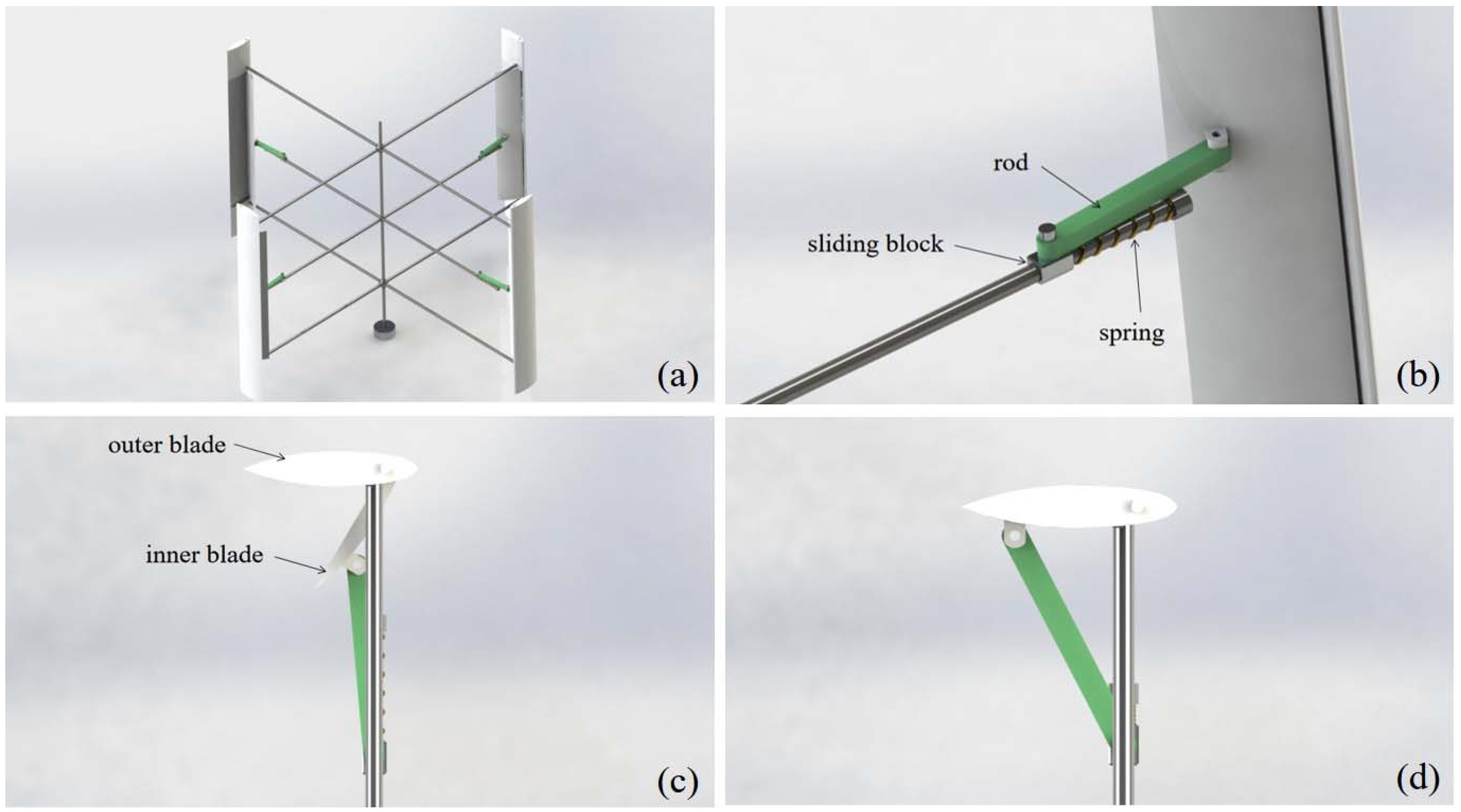
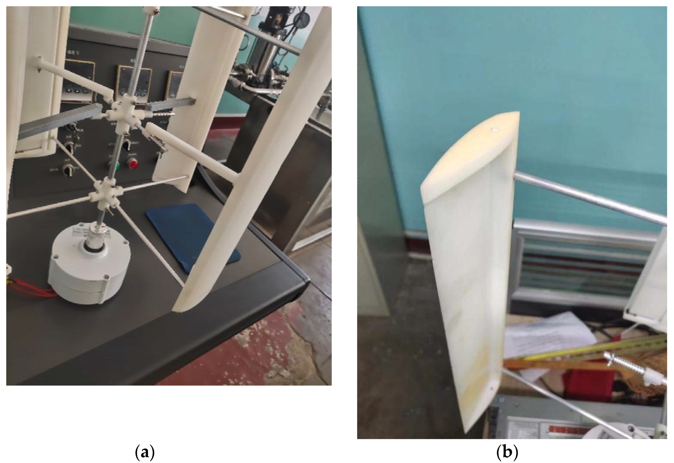
2. Structural Design and Experimental Models

2.1. Structural Design
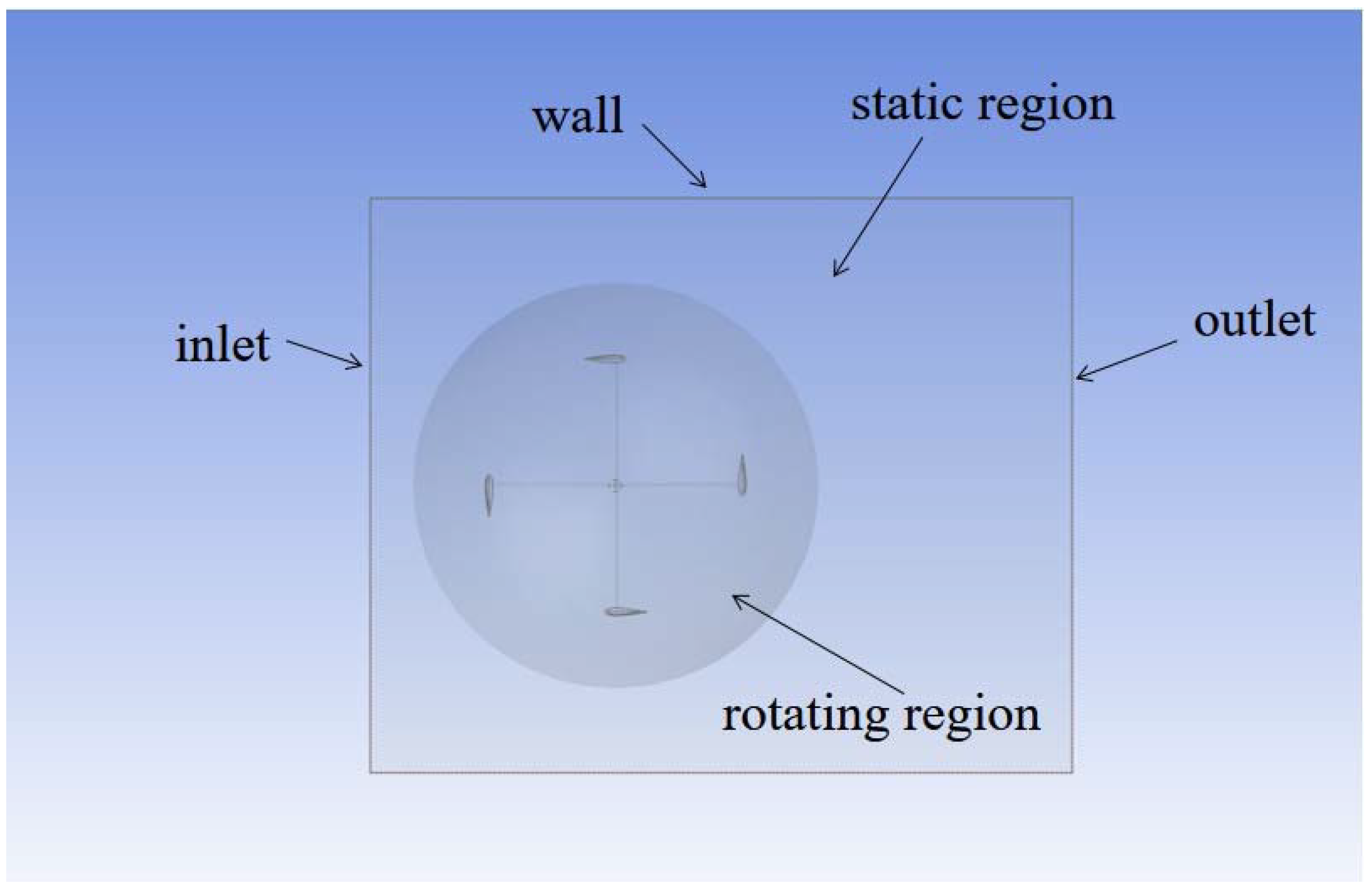
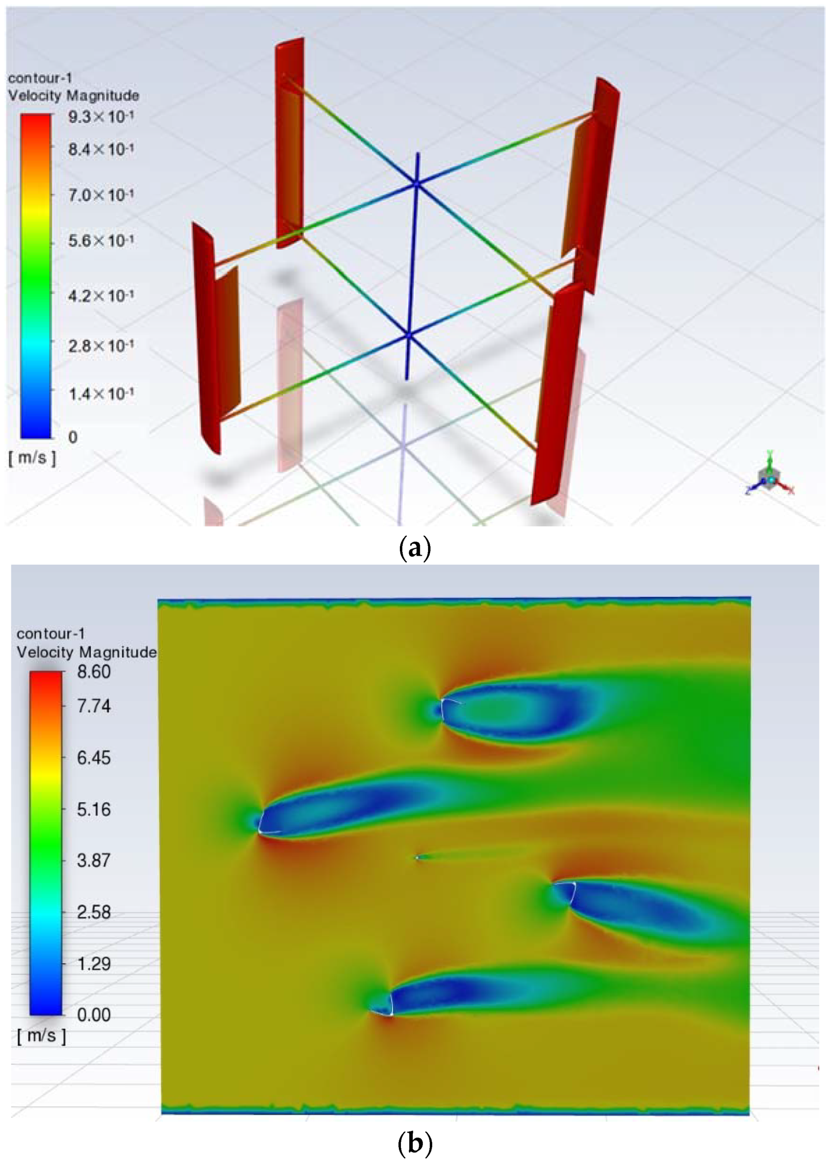
The structural design of the adaptive lift drag composite wind turbine is shown in Figure 1. The innovation of this structural design is that the common lift-type blades are made into an internal hollow structure, as shown in Figure 1d. The blade is divided into inner and outer parts, and a rotation axis is given to the inner blade, so that it can open like a bird’s wing. The opened blade becomes a “V” shaped resistance-type blade with a certain curvature inside. As shown in Figure 1b, a spring is attached to the slider on the bracket, then the inner blade is attached to the bracket with a rod so that when the blade is stationary, the inner blade opens under the thrust of the spring. Figure 1c shows that the wind turbine blade is in the resistance-type shape; with the increasing speed of the wind turbine, the centrifugal force on the sliding block is increasing. Under the action of the centrifugal force, the sliding block will squeeze the spring, making the inner and outer blades gradually close, and the blades gradually transform into the lifting type. Detailed parameters of the wind turbine and blade are shown in Table 1.
This kind of structural design has the following advantages: (1) By taking advantage of the natural aerodynamic advantages of the resistance blades, the starting wind speed of the fan can be greatly reduced, and the self-starting performance of the wind turbine can be improved. (2) When the rotating speed is increased, the blade can be changed to the lift type independently without the help of external force. (3) The modified blades have a complete aerodynamic profile and do not affect the high-speed rotating performance and energy utilization of the wind turbine. By adjusting the stiffness coefficient of the spring and the mass of the slider, it can control the rotating speed when the blade changes configuration.

2.2. CFD Model

In this paper, ANSYS2021R1 (Taiyuan China) is used as CFD software [10,11,12]. Based on the closest point between the wind turbine and the boundary wall in all directions, because the vertical axis wind turbine does not focus on calculating the flow of wind in the upper and lower directions of the impeller, the size of the watershed is determined as X+ = 1500 mm, X− = 500 mm, Y+ = 100, Y− = 100 mm, Z+ = 1500 mm, z− = 1500 mm. In the watershed setting, the fluid region is divided into a rotating region and a static region, as shown in Figure 2.
In order to simulate the start-up process of a wind turbine, the CFD model needs to be set to the “passive rotation” operation mode. Therefore, the calculation method of “6DOF + Dynamic grid” is adopted in this paper. When rotating, the mass and moment of inertia of the blade must be applied. In this paper, the “Space Claim” in Fluent is used to calculate the weight, centroid, moment of inertia, and other physical parameters of the impeller model. The density of the blade is set to 1.13 g/cm3, which is the density of fluorescent resin commonly used in the subsequent production of physical models using 3D printing technology.
Because the wind turbine in the calculation model is a rotating component, therefore, this paper adopts the “RNG k-ε” turbulence model [13,14]. The model is derived from the transient “N-S” equation and is treated by a mathematical method called “Renormalization group”. The constant analysis and derivation results in the model are different from the default “Standard k-ε” model, with k and ε items added to the transportation equation, but the form is similar to the k-ε model:
t ( ρ k ) + x i ( ρ k u i ) = x j ( α k μ e f f x j x j ) + G k + G b ρ ε Y M + S k
t ( ρ ε ) + x i ( ρ ε u i ) = x j ( α ε μ e f f ε x j ) + C 1 ε ε k ( G k + C 3 ε G b ) C 2 ε ρ ε 2 k R ε + S ε
where C1ε = 1.42, C2ε = 1.68, Fluent default value, Gk is the turbulent kinetic energy caused by the average velocity gradient, Gb is the turbulent kinetic energy caused by the average velocity gradient, YM is the contribution of wave expansion to the total dissipation rate in compressible turbulence, αε and αk are the k and ε reciprocal of the “TKE Prandtl Number”, and Sk and Sε are user-defined original items.
The meshing results are shown in Figure 3 and Figure 4. In the process of the impeller rotation, the grid of the rotating region is refreshed and reconstructed at every step to ensure the accuracy of the simulation. The mesh in this region is adaptively encrypted by “meshing”, and a boundary layer is added to the blade wall. The settings of the boundary layer adopt the default option of the “meshing” system, using smooth transitions. The growth rate is 1.2, the transition ratio is 0.272, and the maximum number of layers is five. At the same time, in order to avoid the overlap between the dynamic mesh area and the static mesh area meshing, the junction surfaces of the moving mesh area and the static mesh area are refined, and the “Behavior” option in the advanced meshing settings of the interface is changed from “soft” to “hard”, as shown in Figure 4.
To balance the accuracy of the data and the amount of calculation during the experiment, it is necessary to carry out the grid independence verification experiment. Here, the natural wind speed, u, is selected as 6 m/s, static moment coefficient CM experiment under different meshing schemes for impeller model, with a blade opening angle of Φ = 80° [15,16,17,18,19]. The experimental results are presented in Table 2. It can be seen that when the number of grids reaches 7.51 million, the continuous increase of the number of grids has no significant impact on the results of CM. Therefore, this paper adopts scheme 3 for grid division. That is, the overall number of grids is controlled at about 7.5 million.

2.3. Data Processing

As shown in Figure 5, the velocity cloud diagram of the impeller can be obtained through the “passive rotation” simulation experiment. The velocity of the impeller under this wind velocity can be calculated by Formula (3) based on the velocity of the impeller tip and impeller radius.
N = V 2 π R
The V is the velocity of the blade tip when the impeller rotates under force, m/s, R is the impeller radius, m, and N is the rotating speed of the impeller, r/s. The blade tip speed ratio is an important parameter to measure the rotation speed of the wind turbine. The ratio of the tangent velocity of the outside diameter to the inlet velocity is the ratio of the tip velocity of the wind turbine blade. The calculation formula is:
λ = V U = ω R U
where U is the incoming wind speed, that is, the speed of natural wind before entering the wind turbine, m/s, and ω is the angular speed of wind turbine impeller rotation, rad/s.
The ratio of the power, P, obtained by the wind turbine to the wind power E in the swept area is defined as the wind energy utilization factor, CP, also known as the power factor, which is the key parameter to measure the wind energy efficiency obtained by the vertical axis wind turbine. The torque coefficient, Ct, in this paper, also known as the dynamic moment coefficient, is a dimensionless treatment of the torque, T, received by the wind turbine and an important index to measure the rotation performance of the vertical axis wind turbine [20,21,22,23,24]. The calculation formula is:
C p = P E = T ω 0.5 ρ U 3 A
C t = T 0.5 ρ U 2 A
where T is the torque generated by the wind turbine rotor, N·m, A is the swept area of the blade in the wind field, m2, and ρ is the density of air, 1.29 kg/m³. The static torque coefficient, CM, which is also used in this article, and the dynamic torque coefficient, Ct, are both parameters that indicate the size of the blade torque, and it describes the moment trend of the blade model at rest [25,26,27,28,29,30,31].
In this article, because the opening angle of the blade is controlled by the centrifugal force of the slider when the wind turbine rotates, the distance required for the slider to be closed can be calculated by the centrifugal force generated by the slider at a certain speed and the distance required for the slider when the blade is closed, and the size of the strength coefficient, k, required for the spring used to control the movement of the slider can be calculated, and the calculation formula is:
k S = m v 2 r
where S is the sliding block moving range, m, m is the mass of the slider, v is the linear speed when the slider rotates with the wind turbine, m/s, and r is the radius of the slider at this time, m.

3. Experimental Results and Discussion

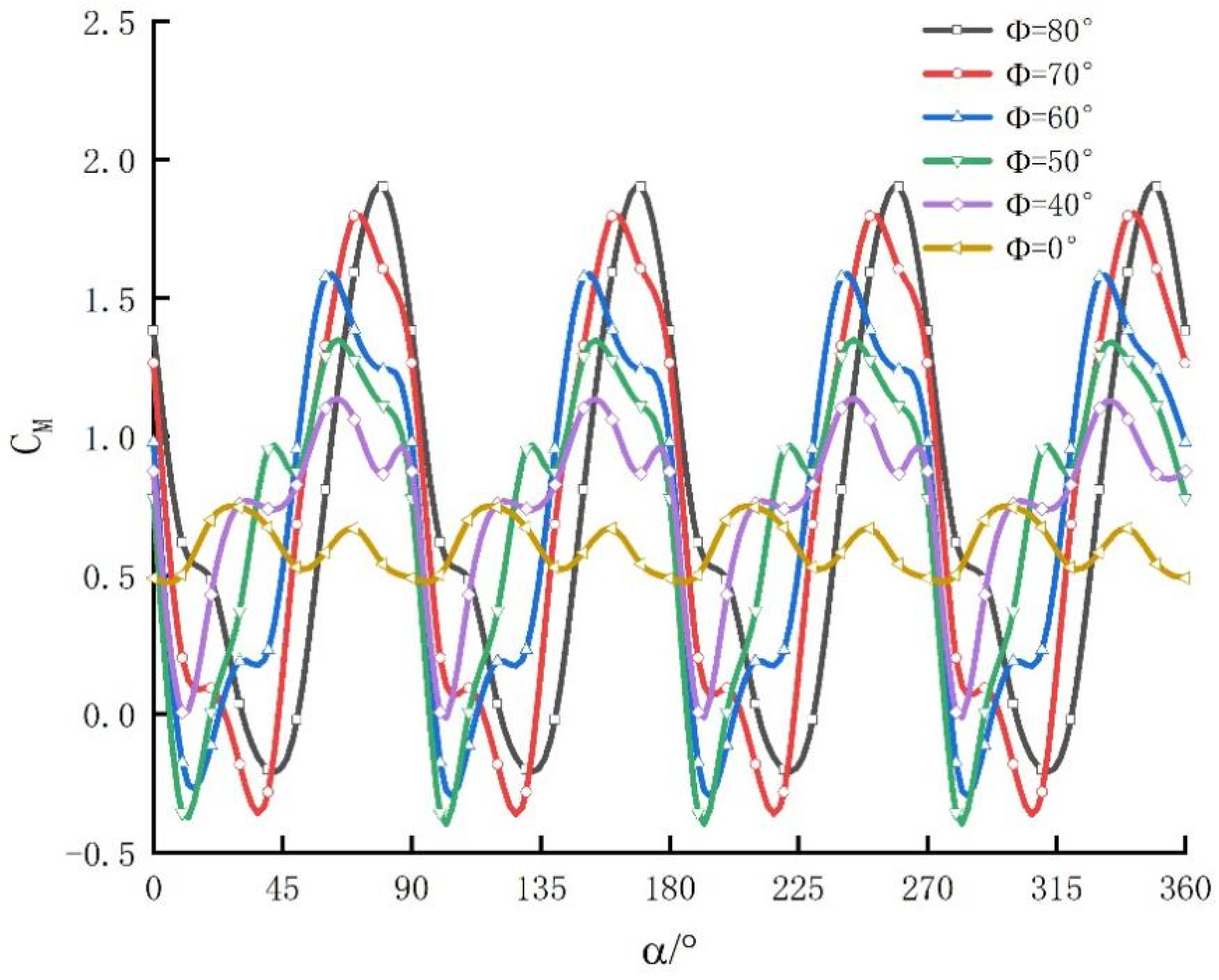
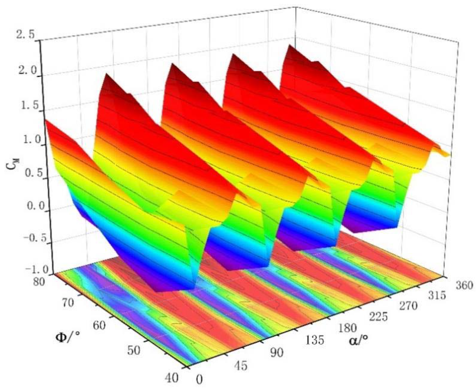
3.1. Analysis of Influence of Blade Opening Angle on Wind Turbine

The structural design in this paper makes the opening angle of the blade value, Φ, range from 0° to 80°. The lift type at Φ = 0° and the resistance type at Φ > 0°. In order to ensure the self-starting performance of the wind turbine, the blade should be kept at Φ > 0° when starting. Therefore, the size of Φ is an important factor affecting the self-starting performance of the impeller; comparative experiments on static torque coefficient, CM, are performed on impellers with different Φ angles in one rotation cycle, and the angle, α, of the blade range is 0~360°, where the wind speed of the incoming flow is U = 6 m/s.
The experimental results are shown in Figure 6 and Figure 7. As can be seen from Figure 6, when Φ > 0°, the blades are in resistance shape, with four peaks in one rotation cycle, because the wind turbine impeller has four blades. With the gradual decrease of Φ, the peak point of the CM curve gradually moves to the left, and the size of the peak gradually decreases, which indicates that the torque of the impeller is gradually reduced, which is not conducive to the self-starting of the impeller of the wind turbine. At Φ > 40°, the amplitude of the CM curve increases, and negative values appear, indicating that the impeller is disturbed by negative torque at these angles.
However, compared with the whole rotation cycle, the occurrence range of negative torque is very narrow. The maximum influence is at Φ = 80°, and the negative torque corner area accounts for 18% of the total cycle. In terms of numerical value, the total value of the negative torque in the cycle is 3% of the positive torque, indicating that the negative torque region has little impact on the overall operation of the impeller. As can be seen from the three-dimensional surface plot in Figure 7, as Φ decreases, the CM gradually becomes flattened with the changing trend of α, and the negative torque region gradually disappears.
In summary, the impeller has the largest CM peak at Φ = 80°; compared with Φ = 0°, the peak value of CM can be increased by up to 1.82 times, although there is a negative torque area, but the impact of relative positive torque is small and the impeller can still maximize CM. Therefore, under the static state of the wind turbine, the opening angle of the blade, Φ, shall be at 80°, so that, in theory, the wind turbine has the best starting performance.

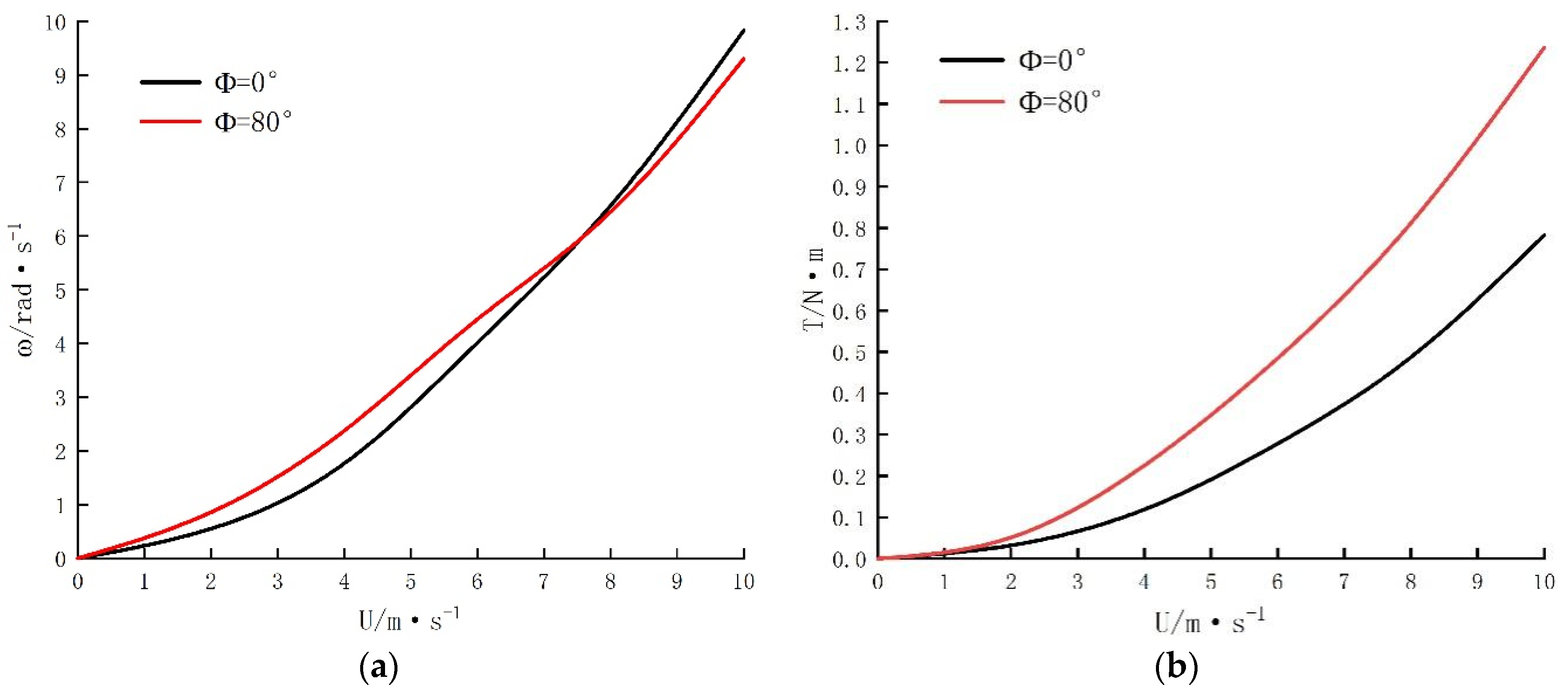
3.2. Impact Analysis of Wind Speed on Lift Drag Combined Wind Turbine

The wind turbine model in this article requires a torque of 0.15 N to start after installing a 100 W dynamo. Generator parameters are shown in Table 3. In order to further analyze the degree of improvement of the resistance pattern blade on the self-starting performance of the wind turbine, a passive rotation experiment was performed on the lift pattern of Φ = 0° and the resistance pattern blade model of Φ = 80° at a wind speed of 0–10 m/s, and the stabilized speed, ω, was compared with the starting torque, T; thereby, the experimental data in Figure 8 were obtained.
As can be seen from Figure 8a, when U < 7.5 m/s, the ω of the resistance pattern blade is higher than the lift type. When U ≥ 7.5 m/s, the disadvantages of the blades of the resistance pattern at high speeds begin to appear, and the ω of the impeller at high wind speeds is lower than that of the lift type due to the excessive windward area. Through the calculation of the ordinate data, it can be concluded that in order to ensure the rotational power and wind energy utilization rate of the wind turbine at a high wind speed, the blade should begin to transform to the lift shape when the ω of the blade reaches 6.204 rad/s in the resistance shape.
In order to achieve the centrifugal force of the slider at a speed of 6.204 rad/s at the speed of the wind turbine, the spring movement can be overcome by 0.0648 m so that the opening angle of the blade, Φ, is changed from 80° to 0°; according to Formula (7), combined with some of the data in Table 2, it can be calculated that the strength coefficient of the required spring, k, is 185.7 N/m.
It can be seen from Figure 8b that, with the continuous increase of wind speed, the starting torque, T, of the resistance pattern blade is larger than that of the lift pattern, and because the resistance shape has a larger windward area, the T of the blade is always greater than the lift pattern in the resistance pattern. It is further proved that the resistance pattern has better self-starting performance than the lift pattern, regardless of the wind speed of the blade. As can be seen from the two curves in Figure 8b, the wind speed of the resistance airfoil with a torque of 0.15 N is 3.2 m/s, while the wind speed of the lift airfoil with Φ = 0° is 4.9 m/s, which indicates that, in this model, the structural design of the lift-drag combination can reduce the starting wind speed of the lift structure wind turbine from 4.9 m/s to 3.2 m/s, which is 34.7%. This helps significantly with the self-starting performance of the wind turbine.
In summary, compared with the ordinary vertical shaft lift-type wind turbine, the vertical axis wind turbine with an adaptive lift resistance composite structure can reduce the starting wind speed of the wind turbine by up to 34.7%; when the speed of the wind turbine reaches 6.204 rad/s after starting, the wind turbine should be converted to the lift shape, which can ensure the rotation performance of the wind turbine at high speed.

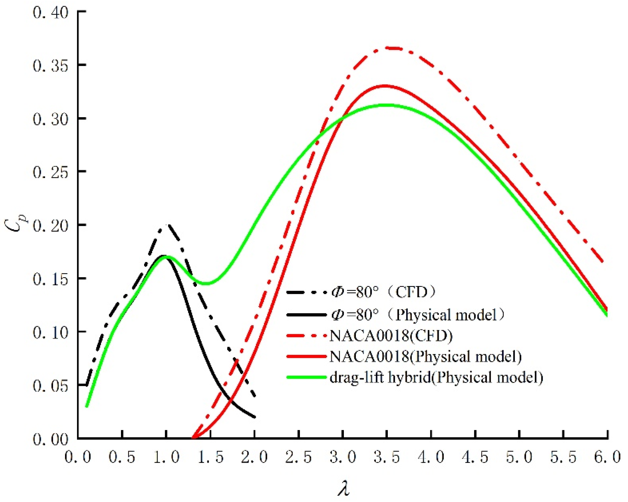
3.3. Effects of Different Tip Speed Ratios on the Performance of Wind Turbines with Drag Configuration

Figure 9 shows the starting characteristic curve of the Φ = 80° resistance-type blade at U = 6 m/s, and shows the change curve of the speed, ω, and dynamic torque coefficient, Ct, of the impeller within 0 to 4 s of the operating time under the condition of passive rotation without load. As can be seen from the figure, after the wind turbine is started under the force of wind energy, Both Ct and ω show periodic fluctuations, which is due to the fact that the wind turbine has four blades, and each blade turns over 90°, which is a parameter cycle. After starting, Ct rises from 0 and reaches the first peak at around 0.08 and then begins to descend, indicating that the blade has begun to turn. Ct’s curve over time is wavy, and the period peak shows a downward trend.
On the other hand, ω shows a wave-like increasing trend after starting up, and the cycle peak is climbing constantly. The change gradient of ω is related to the size of Ct. When the value of Ct is relatively large, the ascending gradient of ω is large, indicating that the gradient of ω is inversely proportional to the size of Ct, which is the operation law of composite rotating components. As can be seen from the curve in the figure, the wind turbine completes a blade rotation cycle at 3.2 s after start-up; that is, the wind turbine rotates through 90°.
In order to further verify the data reliability of the simulation experiment, a physical model experiment is conducted here, and the data is collected to plot the relationship curve between the leaf tip speed ratio and the wind energy utilization rate of the wind turbine, and the data is compared with the simulation data. The wind turbine model in this paper is made of aluminum alloy brackets and fluorescent resin blades obtained by 3D printing, as shown in Figure 10.
As shown in Figure 11, the wind tunnel equipment adopts a small open DC type low-speed jet wind tunnel; the wind tunnel is 6.7 m long and 2.35 m wide, and the air outlet size is 0.4 m × 0.4 m. Wind speed range is 1–15 m/s, airflow is <0.2 m/s, turbulence is ≤0.5%, and airflow declination is ≤0.5.
An anemometer was used in the experiment to monitor wind power, as shown in Figure 12. The model of the anemometer is a “DP3000”, equipped with a 300 mm-long L-type pitot tube and with a working pressure range of −2000~+2000 Pa, a wind speed measurement range of 0.40~30.00 m/s, a maximum overload capacity of 200%, and an error rate of 1%. It can bear a maximum temperature of 800° and has a weight of 0.3 kg.
As shown in Figure 13, in order to explore the variation of the wind energy utilization, Cp, with a leaf tip speed ratio, λ, of the wind turbine model and the influence of the drag-lift combination design on the performance of the wind turbine, the numerical simulation experiment and physical experiment of U = 6 m/s were carried out on the drag model of Φ = 80°, respectively. Numerical simulation experiments and physical experiments were performed on the NACA0018 lift model with Φ = 0°; because the simulation cannot accurately simulate the change process of the blade and the deformation of the spring, only physical test experiments were carried out here on the variable blade model of the drag-lift combined wind turbine.
As can be seen from the figure, the data curves of the physical experiments are smaller than the simulation data curves under the same conditions, which is because there are more unstable factors in the physical experiments, including the friction of the shaft components and the uneven wind speed, etc. However, the data curve of the overall physical experiment is consistent with the data curve of the simulation, and after calculation, the place with the largest error rate is the peak part of the lift blade, where the physical experiment has an error rate of 9.1% compared with the simulation, and the error is still within a reasonable range with reference to the analysis of interference factors.
The black curve and red curve in the figure show the characteristics of the drag blade and the lift blade in terms of wind energy utilization, and we can see that the dominant part of the drag blade is under the low λ, and the CP peaks near λ = 1. The advantage of the lift-type blade is at a high leaf tip speed ratio, and CP peaks near λ = 3.5. Such characteristics are in line with the aerodynamic characteristics of lift and drag blades. Due to the defects of the traditional single design, the lift-type wind turbine has good aerodynamic characteristics at high speed, but the CP is extremely low in the area with a lower λ; the drag blade has a better wind energy utilization rate than the lift blade in the λ area of 0–1.5.
The drag-lift hybrid blade proposed in this paper combines the advantages of the lift-type blade and the drag-type blade in aerodynamic performance, and at the same time improves the self-starting performance of the wind turbine; it also gives the lift-type blade a CP compensation under low λ. As can be seen from the green curve in the figure, the drag-lift hybrid blade proposed in this paper has the partial curve characteristics of the drag-type blade in the lower part of the λ, and the partial curve characteristics of the lift-type blade in the higher part of the λ, which has the advantages of both blades. Observed from the local characteristics part of the curve, with the increase of λ, the curve of the drag-lift hybrid blade is first consistent with the trend of the drag blade, and then after the peak, there is a slight decline, but it is still higher than the curve of the lift blade, which is due to the fact that the drag blade has begun to transform to the lift type here, but the blade opening angle, Φ, is not completely closed, and the Φ at this time should be less than 80° but still greater than 0°. When λ reaches around 3.5, we find that the curve peak of the drag-lift hybrid blade is less than the peak of the pure lift-type blade, which is due to the fact that other parts of the drag-lift hybrid structure affect the overall aerodynamic performance of the wind turbine, including slides, connecting rods, springs, and other parts. However, according to comprehensive analysis, wind turbines with drag-lift hybrid blades have a wider high CP range than traditional lift blades, indicating that their overall utilization rate of wind energy is higher. Although the design of the structure costs a small part of CP at high λ, the drag-lift hybrid compensates the wind energy utilization in low λ areas.

4. Conclusions

In order to improve the self-starting performance of the lift-type wind turbine and reduce the starting wind speed of the wind turbine, this paper, based on a symmetrical airfoil NACA0018, proposes an adaptive drag-lift hybrid vertical axis wind turbine structure, and analyzes the self-starting performance of the design and the factors affecting the power of the wind turbine by combining numerical simulation and physical experiments, and draws the following conclusions:
The wind turbine has the best self-starting performance when the opening of the internal and external blades of the wind turbine is 80°. At U = 6 m/s, the static torque coefficient, CM, of ordinary lift blades can be increased by up to 1.82 times.
The adaptive lift resistance compound wind turbine blades proposed in this paper can effectively expand the range of working wind speed of vertical axis wind turbines and improve the efficiency of low-speed wind turbines. When the wind speed is at 0–10 m/s, the resistance pattern of Φ = 80° can reduce the starting wind speed of ordinary vertical axis wind turbines based on NACA0018 by 34.7%. At U = 6 m/s and λ = 1.1, the wind energy utilization rate of the wind turbine in the resistance pattern reaches the maximum.
The design of the slider enables the blade to adapt to the change of form according to the speed, in order to ensure the rotational power and wind energy utilization rate of the wind turbine at U > 8 m/s, the lift-resistance composite wind turbine should be converted to the lift-type when the speed reaches 6.204 rad/s under the resistance form. Adaptive control of the blade deformation at this speed can be achieved when the stiffness coefficient of the spring is 185.7 N/m
In terms of wind energy utilization, the adaptive lifting resistance composite wind turbine has the performance characteristics of lift blade and resistance blade at the same time, and compared with the ordinary lift blade, the wind energy utilization rate of the wind turbine in the low leaf tip ratio area is improved significantly. At the same time, the increase in components has a weak impact on the energy utilization rate of the wind turbine in the high leaf tip ratio area, which is also where the structural design is not worth further optimization.
This paper proposed a drag-lift hybrid wind turbine that can change the blade form adaptively according to the wind speed. It combined the advantages of a lift-type wind turbine and a resistance-type wind turbine. Compared with the design of existing wind turbines, the drag-lift hybrid wind turbine improved not only the utilization rate of wind energy, but also the self-starting performance. It provided a new perspective for the design and development of wind turbines. More importantly, the drag-lift hybrid wind turbine improved energy efficiency and promotes the development of new energy.

Author Contributions

Conceptualization, methodology, Q.G. and S.L.; investigation and resources, Q.G., S.L. and H.Y.; software, visualization and data curation, S.L.; validation, S.L.; formal analysis, Q.G., S.L. and H.Y.; writing—original draft preparation, Q.G., S.L. and H.Y.; writing—review and editing, Q.G. and S.L.; supervision, project administration, and funding acquisition, Q.G. and H.Y. All authors have read and agreed to the published version of the manuscript.

Funding

This research was funded by the Shanxi Provincial Government through the Natural Science Foundation of Shanxi Province, grant number, 20210302123038, and the Research Support Project for Returned Overseas Chinese in Shanxi Province, grant number, 2020-110.

Institutional Review Board Statement

Not applicable.

Informed Consent Statement

Not applicable.

Data Availability Statement

Not applicable.

Conflicts of Interest

The authors declare no conflict of interest.

References

  1. Karthikeyan, N.; Kalidasa Murugavel, K.; Arun Kumar, S.; Rajakumar, S. Review of aerodynamic developments on small horizontal axis wind turbine blade. Renew. Sustain. Energy Rev. 2015, 42, 801–822. [Google Scholar] [CrossRef]
  2. Almekhlafi, M.A.A.; Al-Wesabi, F.N.; Eltahir, M.M.; Mustafa Hilal, A.; El-Kustaban, A.M.; Motwakel, A.; Yaseen, I.; Ahmed Hamza, M. Analysis and Assessment of Wind Energy Potential of Almukalla in Yemen. Comput. Mater. Contin. 2022, 72, 3113–3129. [Google Scholar] [CrossRef]
  3. Zhu, J.; Huang, H.; Shen, H. Self-starting aerodynamics analysis of vertical axis wind turbine. Adv. Mech. Eng. 2015, 7. [Google Scholar] [CrossRef] [Green Version]
  4. Fang, F. Study on Aerodynamic Characteristics of Combined Vertical Axis Wind Turbine with Lift Drag Composite Starting Structure; Northeast Agricultural University: Harbin, China, 2018. [Google Scholar]
  5. Liu, Q.; Miao, W.; Ye, Q.; Li, C. Performance assessment of an innovative Gurney flap for straight-bladed vertical axis wind turbine. Renew. Energy 2022, 185, 1124–1138. [Google Scholar] [CrossRef]
  6. Li, Y.; Zhao, S.; Qu, C.; Feng, F.; Kotaro, T. Effects of Offset Blade on Aerodynamic Characteristics of Small-Scale Vertical Axis Wind Turbine. J. Therm. Sci. 2019, 28, 326–339. [Google Scholar] [CrossRef]
  7. Wu, S.; Bao, D.; Liu, X. Structural design and performance analysis of a new variable pitch wind turbine. Res. Energy Resour. 2022, 40, 350–355. [Google Scholar]
  8. Aboujaoude, H.; Beaumont, F.; Murer, S.; Polidori, G.; Bogard, F. Aerodynamic performance enhancement of a Savonius wind turbine using an axisymmetric deflector. J. Wind Eng. Ind. Aerodyn. 2022, 220, 104882. [Google Scholar] [CrossRef]
  9. Yao, Z.; Wang, F.; Dreyer, M.; Farhat, M. Effect of trailing edge shape on hydrodynamic damping for a hydrofoil. J. Fluids Struct. 2014, 51, 189–198. [Google Scholar] [CrossRef] [Green Version]
  10. Ge, M.-W.; Ke, W.-M.; Chen, H.-X. Pitch control strategy before the rated power for variable speed wind turbines at high altitudes. J. Hydrodyn. 2018, 31, 379–388. [Google Scholar] [CrossRef]
  11. Ma, Y.; Zhu, Y.; Zhang, A.; Hu, C.; Liu, S.; Li, Z. Hydrodynamic performance of vertical axis hydrokinetic turbine based on Taguchi method. Renew. Energy 2022, 186, 573–584. [Google Scholar] [CrossRef]
  12. Celik, Y.; Ingham, D.; Ma, L.; Pourkashanian, M. Design and aerodynamic performance analyses of the self-starting H-type VAWT having J-shaped aerofoils considering various design parameters using CFD. Energy 2022, 251, 123881. [Google Scholar] [CrossRef]
  13. Yao, X.; Han, S.; Dewancker, B. Wind Environment Simulation Accuracy in Traditional Villages with Complex Layouts Based on CFD. Int. J. Environ. Res. Public Health 2021, 18, 8644. [Google Scholar] [CrossRef]
  14. Zhang, Y.; Kang, C.; Pan, C.; Opare, W. Numerical investigation of performance and flow patterns of a modified Savonius hydraulic rotor. IOP Conf. Ser.: Earth Environ. Sci. 2019, 240, 042009. [Google Scholar] [CrossRef]
  15. Wang, Y.; Sun, X.; Dong, X.; Zhu, B.; Huang, D.; Zheng, Z. Numerical investigation on aerodynamic performance of a novel vertical axis wind turbine with adaptive blades. Energy Convers. Manag. 2016, 108, 275–286. [Google Scholar] [CrossRef]
  16. Zeng, Y.-S.; Yao, Z.-F.; Huang, B.; Wang, F.-J.; Wu, Q.; Xiao, R.-F.; Wang, G.-Y. Numerical studies of the hydrodynamic damping of a vibrating hydrofoil in torsional mode. J. Hydrodyn. 2021, 33, 347–360. [Google Scholar] [CrossRef]
  17. Li, Q.A.; Maeda, T.; Kamada, Y.; Murata, J.; Kawabata, T.; Furukawa, K. Analysis of aerodynamic load on straight-bladed vertical axis wind turbine. J. Therm. Sci. 2014, 23, 315–324. [Google Scholar] [CrossRef]
  18. Doerffer, P.; Doerffer, K.; Ochrymiuk, T.; Telega, J. Variable Size Twin-Rotor Wind Turbine. Energies 2019, 12, 2543. [Google Scholar] [CrossRef] [Green Version]
  19. Saad, A.S.; Elwardany, A.; El-Sharkawy, I.I.; Ookawara, S.; Ahmed, M. Performance evaluation of a novel vertical axis wind turbine using twisted blades in multi-stage Savonius rotors. Energy Convers. Manag. 2021, 235, 114013. [Google Scholar] [CrossRef]
  20. Maleki Dastjerdi, S.; Gharali, K.; Al-Haq, A.; Nathwani, J. Application of Simultaneous Symmetric and Cambered Airfoils in Novel Vertical Axis Wind Turbines. Appl. Sci. 2021, 11, 8011. [Google Scholar] [CrossRef]
  21. Ashok Gandhi, R.; Ravinthiran, A.; Palanikumar, K. Design and development of sail type wind turbine with solar panel. Mater. Today Proc. 2021, 46, 3989–3992. [Google Scholar] [CrossRef]
  22. Durkacz, J.; Islam, S.; Chan, R.; Fong, E.; Gillies, H.; Karnik, A.; Mullan, T. CFD modelling and prototype testing of a Vertical Axis Wind Turbines in planetary cluster formation. Energy Rep. 2021, 7, 119–126. [Google Scholar] [CrossRef]
  23. Müller, S.; Muhawenimana, V.; Wilson, C.A.M.E.; Ouro, P. Experimental investigation of the wake characteristics behind twin vertical axis turbines. Energy Convers. Manag. 2021, 247, 114768. [Google Scholar] [CrossRef]
  24. Sakamoto, L.; Fukui, T.; Morinishi, K. Blade Dimension Optimization and Performance Analysis of the 2-D Ugrinsky Wind Turbine. Energies 2022, 15, 2478. [Google Scholar] [CrossRef]
  25. Peng, H.Y.; Zhong, B.W.; Hu, G.; Liu, H.J. Optimization analysis of straight-bladed vertical axis wind turbines in turbulent environments by wind tunnel testing. Energy Convers. Manag. 2022, 257, 115411. [Google Scholar] [CrossRef]
  26. Sun, X.; Zhu, J.; Li, Z.; Sun, G. Rotation improvement of vertical axis wind turbine by offsetting pitching angles and changing blade numbers. Energy 2021, 215, 119177. [Google Scholar] [CrossRef]
  27. Divakaran, U.; Ramesh, A.; Mohammad, A.; Velamati, R.K. Effect of Helix Angle on the Performance of Helical Vertical Axis Wind Turbine. Energies 2021, 14, 393. [Google Scholar] [CrossRef]
  28. Eltayesh, A.; Castellani, F.; Burlando, M.; Bassily Hanna, M.; Huzayyin, A.S.; El-Batsh, H.M.; Becchetti, M. Experimental and numerical investigation of the effect of blade number on the aerodynamic performance of a small-scale horizontal axis wind turbine. Alex. Eng. J. 2021, 60, 3931–3944. [Google Scholar] [CrossRef]
  29. Ma, Y.; Hu, C.; Li, L. Hydrodynamics and wake flow analysis of a Π-type vertical axis twin-rotor tidal current turbine in surge motion. Ocean Eng. 2021, 224, 108625. [Google Scholar] [CrossRef]
  30. Rosado-Hau, N.; Ma, L.; Ingham, D.; Pourkashanian, M. A procedure to predict the power coefficient of vertical axis wind turbines at low tip speed ratios. In Proceedings of the AIAA Scitech 2019 Forum, San Diego, CA, USA, 7–11 January 2019; pp. 1–13. [Google Scholar] [CrossRef]
  31. Rosado Hau, N.; Ma, L.; Ingham, D.; Pourkashanian, M. A critical analysis of the stall onset in vertical axis wind turbines. J. Wind Eng. Ind. Aerodyn. 2020, 204, 104264. [Google Scholar] [CrossRef]
Figure 1. Impeller structure design drawing: (a) overall structure top view, (b) adaptive extension mechanism, (c). resistance-type blade configuration, (d) lift-type blade configuration.
Energies 15 05600 g001
Figure 2. Drainage basin setting diagram.
Energies 15 05600 g002
Figure 3. Gridding display.
Energies 15 05600 g003
Figure 4. Boundary layer settings.
Energies 15 05600 g004
Figure 5. Velocity nephogram. (a). wind turbine speed nephogram. (b). flow field nephogram.
Energies 15 05600 g005
Figure 6. The torque coefficient under different open angles, Φ, changes with the angle of change.
Energies 15 05600 g006
Figure 7. The effect of changes in Φ and α on CM..
Energies 15 05600 g007
Figure 8. Parametric curves of two morphological leaves: (a) rotation rate, (b) self-starting torque.
Energies 15 05600 g008
Figure 9. Startup characteristics.
Energies 15 05600 g009
Figure 10. Physical model of wind turbine: (a) overall structure, (b) blade model.
Energies 15 05600 g010
Figure 11. DC type low speed jet wind tunnel: (a) exterior view of wind tunnel, (b) interior view of wind tunnel.
Energies 15 05600 g011
Figure 12. Anemometer.
Energies 15 05600 g012
Figure 13. Curve of power coefficient with tip speed ratio.
Energies 15 05600 g013
Table 1. Blade Parameters.
Parameter Name/unitNumberParameter Name/UnitNumber
Blade height/mm730Blade offset angle/°0
Blade chord length/mm100Installation angle of outer blade/°90
Number of blades4Sliding block moving range S/m0.0648
Blade sweep area A/m20.964Slider mass/kg0.3
Radius R/mm660Blade opening angle range Φ0–80
Table 2. Grid independent verification scheme.
SchemeNumber of GridsNode NumberCM
13,225,714722,8581.4561
25,341,8741,238,8971.4302
37,512,8531,598,2261.3822
49,371,4582,368,9391.3835
510,252,3932,592,8261.3826
Table 3. Specific parameters of small generator.
Parameter Name/unitNumberParameter Name/unitNumber
Generator modelNE-100WSRated voltage/V12
Starting torque/N·m>0.15Mass/kg3
Rated power/W100Rated speed/rpm750
Working temperature rise/°C<70Insulation classH
Publisher’s Note: MDPI stays neutral with regard to jurisdictional claims in published maps and institutional affiliations.

