Article

Bus Voltage Control of Photovoltaic Grid Connected Inverter Based on Adaptive Linear Active Disturbance Rejection

School of Automation & Electronic Engineering, Qingdao University of Science and Technology, Qingdao 266061, China
*
Author to whom correspondence should be addressed.
Energies 2022, 15(15), 5556; https://doi.org/10.3390/en15155556
Submission received: 6 July 2022 / Revised: 25 July 2022 / Accepted: 28 July 2022 / Published: 30 July 2022
(This article belongs to the Section A2: Solar Energy and Photovoltaic Systems)

Abstract

:
According to the traditional voltage and current double closed-loop control mode, the inverter management strategy for photovoltaic grid connection has insufficient anti-interference ability and slow response. This paper proposes a control strategy that applies adaptive-linear active disturbance rejection control (A–LADRC) to the outer loop control to achieve the purpose of anti-interference. The control strategy uses the linear extended state observer (LESO) to evaluate external interference caused by the change of external conditions and the internal disturbance caused by parameter uncertainty. PD controller compensates the disturbances and adds adaptive control to simplify parameter adjustment. Finally, this paper takes advantage of Lyapunov theory to conduct stability analysis. Compared with the traditional linear active disturbance rejection control (LADRC), the superiority of this control strategy is verified. The experimental results show that the system has better control performance and anti-interference ability in the face of various disturbances.

1. Introduction

With the development of industrialization, in order to provide generous energy required for the process of industrialization, the extensive use of traditional fossil energy has brought pollution to the environment, damaged the ecological balance, and posed a serious threat. The application of solar energy in people’s daily life as a green and environmentally friendly emerging energy is the key to solve this problem [1,2,3,4]. Photovoltaic power generation is a significant mechanism for its development and utilization. As the key link between a PV system and the power grid, the control strategy of the photovoltaic inverter directly determines the security and reliability of a grid-connected PV system. Therefore, the research and development of PV inverter control strategies has attracted more and more attention. The DC bus voltage is regulated by the inverter control strategy, and its output stability will be affected by various external disturbances [5,6]. The traditional double closed-loop PI inverter control strategy has poor control performance in the face of external interference and cannot maintain voltage stability. Therefore, it is very meaningful to propose an effective inverter control strategy to enhance the robustness of bus voltage control.
Reference [7] introduced the structure of photovoltaic inverters and related application schemes and introduced several control schemes applicable to single-phase photovoltaic inverters and three-phase photovoltaic inverters. Reference [8] proposed a grid-connected inverter control method using adaptive fuzzy control (AFC) technology. The controller is designed using the ability of the fuzzy system to approximate the nonlinear function of the grid-connected inverter system. The controller does not need precise parameters and modeling. The update law of the controller parameters is also determined. The availability of the designed controller is proved in an experiment with the controller under different system disturbances, parameters, and modeling uncertainties. This reference proposed an adaptive fuzzy approximation strategy as the inverter control strategy, but its algorithm depended on the provision and support of data information. Reference [9] proposed a method of introducing adaptive control into the control strategy of photovoltaic inverters, which took the bus voltage as the control target and enhanced the stability of the system. Reference [10] proposed a dual integral sliding mode controller (DISMC) to be applied to photovoltaic inverter control. The controller is applied to voltage inner loop control to enhance the ability of inverter to suppress various interferences. Reference [11] proposed a hybrid control method using maximum power point tracking (MPPT) and energy storage control to optimize the power control of the photovoltaic inverter. The control strategy enhances the reliability of power devices and inverters. Reference [12] introduced a fuzzy logic photovoltaic inverter control optimization scheme based on a lightning search algorithm. This controller solved the issue of the function repeated test process in the fuzzy logic controller and verified that the design scheme has good reliability and efficiency. Reference [13] proposed a control strategy of applying the adaptive PI controller to the neutral point clamped (NPC) inverter. The photovoltaic grid-connected NPC inverter has good robustness, but it is prone to the imbalance of bus capacitor voltage. Therefore, the adaptive PI controller is introduced to solve this problem. Reference [14] designed a variable structure sliding mode control scheme, which enhanced the control force of bus voltage and enhances the stability. However, in the design of the control scheme, it is necessary to clarify the value of the load side impedance, which reduces the practicality. Reference [15] proposed an adaptive fuzzy approximation strategy as the inverter control strategy, but its algorithm depended on the provision and support of data information. Reference [15] proposed an ADRC inverter control strategy that applies adaptive control to ESO. This control strategy enhances the robustness of bus voltage control. However, there are complex nonlinear functions in the design process of ADRC, which greatly increases the difficulty of controller design. In reference [16], the fuzzy control algorithm was applied to MPPT control, and an idea of applying the LADRC controller to a double closed-loop control strategy was put forward. This control strategy can effectively deal with the fluctuation of bus voltage when the light intensity changes abruptly. Reference [17] applied ADRC technology to photovoltaic system, and improved inverter control and MPPT control by using ADRC technology. However, the article only discusses the situation when light and temperature change and does not further analyze other disturbances. Reference [18] proposed an improved LADRC control strategy to improve the stability of bus voltage control, improved the structure of LESO, and enhanced the performance of the controller. At the same time, LADRC is also widely used in practical projects with its own advantages. In [19], LADRC was proposed to solve the problem of accurately tracking the planning trajectory of a delta high-speed parallel robot. The internal coupling and interference of the robot are observed and compensated by the state observer to solve the strong coupling problem in the system. Finally, compared with PID control, the experimental results show that the delta high-speed robot with LADRC has better response speed, tracking accuracy and robustness. In [20], LADRC was applied to a Variable Speed Micro Hydropower Station (VS-MHP), which had the function of torque compensation and could realize more effective tracking of speed. In [21], LADRC was applied to the motor control of hybrid electric vehicles to realize the function that the motor output could quickly track the reference speed signal. At the same time, LADRC had also been applied in other engineering fields [22,23,24].
In this paper, taking the DC bus voltage as the control target, a control strategy of A–LADRC inverter is proposed. On the basis of LADRC’s good anti-interference ability, adaptive control is introduced into the PD controller to approximate the optimal parameters, which saves the complex parameter tuning process and improves the control performance of the controller. The main contributions of this paper are as follows:
(1)
Considering the structure diagram of the inverter, KVL law, and KCl law, the mathematical model of the inverter is established. In addition, to solve the AC coupling component that is laborious to analyze in the mathematical model, the mathematical model changes through the coordinate system, which is more instrumental in the design of the controller and the research and analysis of the system.
(2)
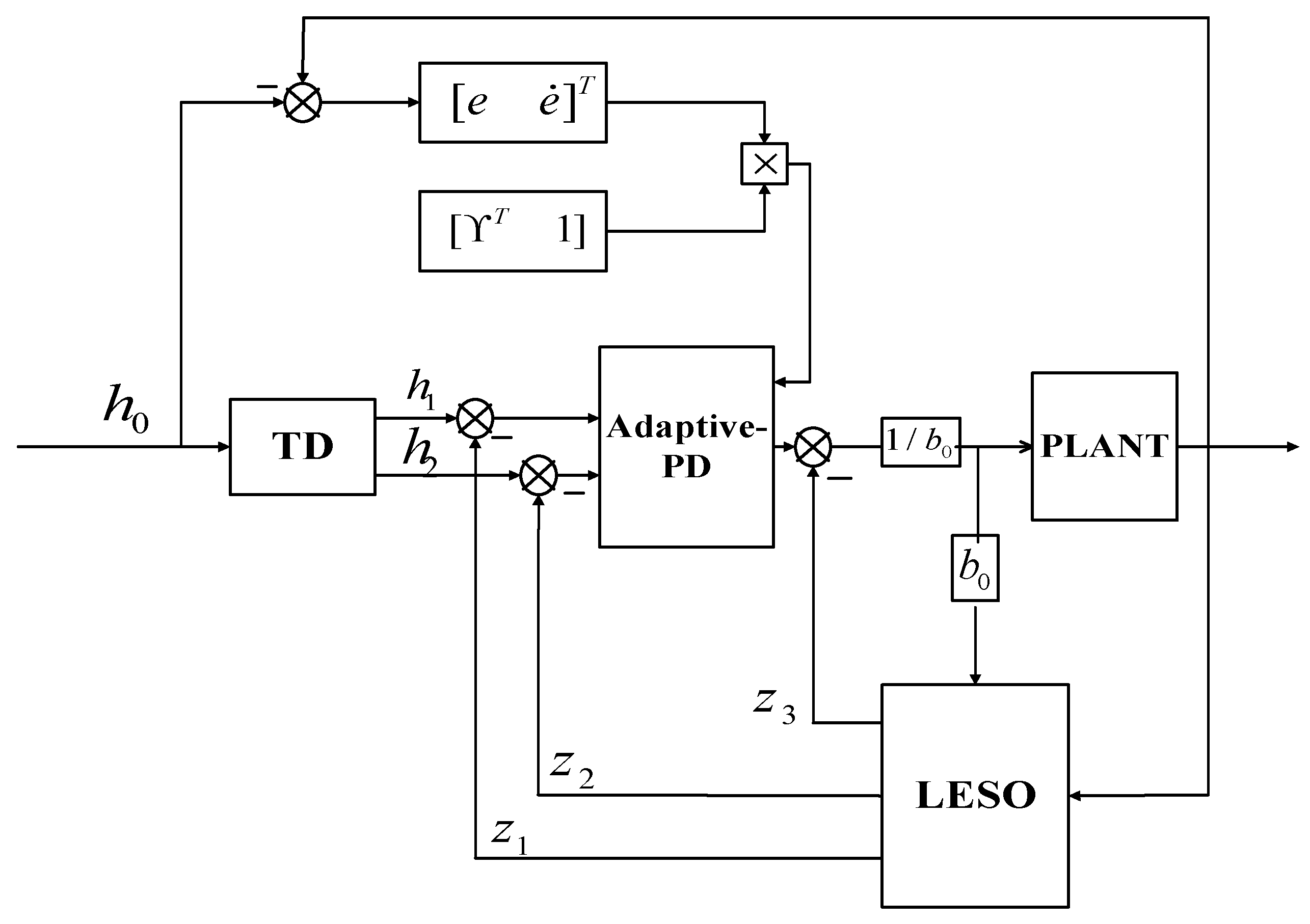
An inverter control strategy of A–LADRC is proposed. In practical engineering, the bus voltage controlled by the inverter will fluctuate under the influence of light mutation, low voltage ride through, and other faults, which will affect the power quality. On the basis of double closed-loop control, this control strategy uses LADRC to enhance the anti-interference ability and designs a good adaptive control scheme and applies it to the PD controller of LADRC. By changing the k p and k d in real time, the controller has better control performance in the initial transient process and fault occurrence.
(3)
It is proved that the system is uniformly stable by Lyapunov theory, and it is further proved that the system is uniformly asymptotically stable by the Barbalat theorem. Compared with LADRC and PI, this scheme has stronger anti-interference ability and less response time in the case of light mutation and low voltage ride through fault.
Other contents of this article are as follows: Section 2 establishes the mathematical model of the inverter; Section 3 designs the control scheme according to the mathematical model; Section 4 analyzes the stability; Section 5 and Section 6 analyze the experimental results; and Section 7 summarizes the full text.

2. Mathematical Model of Grid-Connected PV Inverter

The topology of the inverter is shown in Figure 1. Where, L represents the AC measured filter inductance, R represents the equivalent series resistance of the filter inductance, C l represents the AC measured filter capacitance, and C represents the DC side capacitance.
In the figure, only one switching device in each phase is in the on state, and the expression of the switching function S k is shown in Formula (1).
S k = { 1 , Any   upper   bridge   arm   operation   0 , Any   lower   bridge   arm   operation
In combination with Figure 1, KVL law, and KCl law, the following assumptions are made:
1.
The power supply is equivalent to three-phase symmetrical sinusoidal voltage source.
2.
The switch is considered to be an ideal switch without switching delay and loss.
Therefore, the mathematical model of PV inverter is as follows:
{ L d i g a d t = e g a R i g a u g a L d i g b d t = e g b R i g b u g b L d i g c d t = e g c R i g c u g c C d U d c d t = k = a , b , c S k i g k i s
where, i g k ( k = a , b , c ) represents the current component at the network side, e g k ( k = a , b , c ) represents the grid voltage, u g k ( k = a , b , c ) represents the inverter terminal voltage component, U d c represents the DC bus voltage, and i s represents the output current of the previous converter.
From Formula (2), it can be seen that the mathematical quantities of each phase of the model are AC variables and change according to the trend, which increases the complexity of the inverter system design [25,26]. Therefore, the mathematical model in the two-phase static coordinate system can be obtained through the Clark transformation of Formula (2).
T c l a r k e = 2 3 [ 1 1 2 1 2 0 3 2 3 2 ]
{ d i g α d t = 1 L ( e g α R i g α u g α ) d i g β d t = 1 L ( e g β R i g β u g β ) d U d c d t = 1 C ( k = α , β S k i g k i s )
where, i g k ( k = α , β ) , e g k ( k = α , β ) , and u g k ( k = α , β ) represent the current component at the network side, grid voltage component, and inverter terminal voltage component on the α and β axes, respectively. Formula (4) represents the mathematical model of the inverter in a two-phase static coordinate system obtained by Clark transformation. This method realizes the independent control of the mathematical quantities on the α-axis and β-axis. However, there is still an AC component in the model, so Park transform is used to further convert the inverter model.
T P a r k = [ sin ω t cos ω t cos ω t sin ω t ]
{ d i g d d t = R L i d + ω i q + 1 L e g d 1 L u g d d i g q d t = R L i q + ω i d + 1 L e g q 1 L u g d d U d c d t = 1 C 3 2 x = d , q S x i g x i s
where, i g k ( k = d , q ) , e g k ( k = d , q ) , and u g k ( k = d , q ) represent the current component at the network side, grid voltage component, and inverter terminal voltage component on the d and q axes, respectively. ω is the angular frequency.
Assuming that the reactive current of the q-axis is zero, Formula (6) can be further derived as Formula (7).
d 2 U d c d t 2 = 3 2 k = d , q S k ( e g k L C u g k L C ) 3 S d R i g d 2 L C 3 ω S q i g d 2 C 1 C d i s d t
Through the transformation between the above coordinate systems, the mathematical model in the two-phase rotating coordinate system is obtained, and the AC component in the model is converted into a DC component. The mathematical model of the inverter is more conducive to the design of the controller and the research and analysis of the system to guarantee the operation of the PV system.

3. Inverter Control Strategy

In the practical application of a PV system, the whole PV system is often affected by various external disturbances, resulting in the fluctuation of bus voltage. However, traditional control strategies cannot effectively solve this problem [27]. Therefore, based on the traditional control strategy, LADRC is applied to the outer loop to reduce the impact of various disturbances on the bus voltage. To resolve the poser that it is laborious to effectively determine the parameters of PD controller in LADRC, adaptive control is introduced to solve this problem, and the observation error of LESO is also improved. A control strategy of A–LADRC for the inverter is proposed. The structure diagram of the inverter control scheme is shown in Figure 2.
The main function of A–LADRC is to obtain the current reference value on axis d by adjusting the error signal between the measured DC bus voltage and the reference signal. PI control is adopted in the inner loop control strategy, and the output of LADRC is taken as the reference to compare with the measured current component. Inputs the modulation signal are then obtained through coordinate inverse transformation into space vector pulse width modulation in order to obtain the driving signal to control the turn-on and turn-off time of MOSFET and complete the control of DC bus voltage [28,29].
LADRC is composed of a linear extended observer (LESO), tracking differentiator (TD), and linear error state feedback control law (LESF) [30,31]. The structure of the controller is shown in Figure 3.
The algorithm of tracking differentiator is given in the following formula [32]:
{ h 1 ( t + 1 ) = h 1 ( t ) + a h 2 ( t ) h 2 ( t + 1 ) = h 2 ( t ) + h f h a n ( h 1 h 0 , i 2 , b , a )
where, b is the fast factor, a is the sampling time, f h a n ( ) is the fastest control synthesis function, h 1 ( t ) is the initial signal tracking signal, and h 2 ( t ) is the initial signal differential tracking signal.
Formula (7) shows that the model is a second-order system. Therefore, the design of LESO is third order according to the order of the model. The mathematical model of the inverter can be extended to:
{ h ˙ 1 = h 2 h ˙ 2 = f n ( t ) + g n ( t ) u ( n ) + m ( t ) y = h 1
where, U d c = y , i g d = u ; h 1 , h 2 are the measurable state quantity of the system; f n ( t ) , g n ( t ) are the nonlinear function; and m ( t ) is the destabilization of the system.
The nondeterminacy of the internal parameters and the external disturbance are positioned as the total disturbance D ( v , u ( n ) ) [33], whose formula is as follows:
D ( h , u ) = f n ( t ) + [ g n ( t ) b 0 ] u ( n ) + m ( t )
Let z 1 = h 0 , z 2 = h ˙ 0 , z 3 = D ( h , u ) , the mathematical model of inverter in extended state space is set up to take stock of the total destabilization of inverter [34]. According to Formula (9):
{ z ˙ 1 = z 2 z ˙ 2 = z 3 + b 0 u z ˙ 3 = D ˙ ( h , u )
z 1 , z 2 , z 3 can be obtained by LESO real-time estimation in the following forms:
{ z ^ ˙ 1 = z 2 β 1 ( z ^ 1 y ) z ^ ˙ 2 = z 3 β 2 ( z ^ 1 y ) + b 0 u z ^ ˙ 3 = β 3 ( z ^ 1 y )
where, β 1 , β 2 , and β 3 are observer gains. By selecting appropriate β 1 , β 2 , and β 3 , LESO can realize real-time tracking of the control objective, differential of the control objective, and total disturbance. The observation gain can be obtained from its characteristic equation, which can parameterize the eigenvalue at the observation bandwidth.
Θ ( s ) = s 3 + β 1 s 2 + β 2 s + β 3 = ( s + ω 0 ) 3
where, β 1 = 3 ω 0 , β 2 = 3 ω 0 2 , β 3 = ω 0 3 , ω 0 is the bandwidth of LESO.
Remark 1.
LESO can be designed without an accurate mathematical model, and its design is only related to the order of the system. The inverter model is a second-order system, so this paper designs a third-order LESO. It can extend the unknown disturbance in the system and use the output feedback to observe the extended state of the extended disturbance, and then use the PD controller to compensate.
z ^ 1 , z ^ 2 , z ^ 3 are the estimated values of the bus voltage, differential of the bus voltage, and total disturbance under extended state observation, respectively. The output control signals of the PD controller are as follows:
u p d = k ^ p ( h 1 z 1 ) + k ^ d ( h 2 z 2 ) + h ¨ 0
Therefore, the expression of LESF in LADRC can be further obtained
u L = ( u p d z ^ 3 ) / b 0
Remark 2.
In the face of complex and variable external disturbances, conventional LADRC is often difficult to set the optimal k p and k d . The adoption of adaptive control reduces the tracking error caused by the controller parameters and simplifies the parameter setting. At the same time, it helps to analyze the stability of the whole system and provides a new way to make full use of the optimal control performance of LADRC.
The values of k p and k d can affect the control performance and anti-interference ability of the controller, so it is particularly important to select the appropriate values of k p and k d . In order to reduce the complexity of the parameter adjustment process, this paper introduces the adaptive control real-time adjustment k p and k d and designs the adaptive law according to the system and controller. At the same time, the introduction of adaptive law is conducive to stability analysis.
Assumption 1.
Considering the tracking error e 2 = y h 0 , the filtering tracking error is defined as:
η = [ ϒ T 1 ] e 2
where, ϒ = [ t 1 t 2 ] T is the properly selected modulus vector, so that when η 0 , e 2 0 is satisfied.
Taking the derivative of η ,
η ˙ = h ˙ 2 h ¨ 0 + [ 0 ϒ T ] e 2
where
h ˙ 2 = f n ( t ) + [ g n ( t ) b 0 ] u + m ( t ) = G ( h , u ( n ) )
In order to further derive the approximate value of the tracking signal, the above formula can be further deduced to be:
n = G ^ 1 ( h , ξ )
where, ξ = G ^ ( h , n ) , ξ is designed as follows:
ξ = w η + u p d [ 0 ϒ T ] e 2    
where, w is any positive parameter.
Add and subtract G ^ ( h , n ) on the right side of h ˙ 2 to further obtain the relationship between h ˙ 2 and G ( h , u ) :
h ˙ 2 = G ˜ ( h , u , n ) + G ^ ( h , n )
Assumption 2.
G ^ ( h , n ) is an arbitrary approximation of G ( h , u ) , G ˜ ( h , u , n ) is an infinitesimal value, let G ˜ ( h , u , n ) = 0 .
Substitute Formulas (15), (20), and (21) into Formula (17) to obtain:
η ˙ = w η + k p ( h 0 z ^ 1 ) + k d ( h ˙ 0 z ^ 2 )

4. Stability Analysis

Assumption 3.
The signal in the system is bounded, and the tracking error approaches zero.
Theorem 1.
Formula (13) shows that the mathematical model of inverter is a nonlinear system. The following adaptive law is designed, and the expression of the adaptive law is as follows:
k ^ ˙ p = [ η k p ( h 0 z ^ 1 ) μ ] / k ˜ p
k ^ ˙ d = [ η k d ( h ˙ 0 z ^ 2 ) χ ] / k ˜ d
Because k ˜ p and k ˜ d are in the denominator position, when their values take 0, the adaptive law tends to infinity, and there is a singularity problem. To avoid this issue, Formulas (23) and (24) are rewritten:
k ^ p = 0 t { [ η k p ( h 0 z ^ 1 ) μ ] / k ˜ p } d h + k p 0
k ^ d = 0 t { [ η k d ( h 0 z ^ 1 ) χ ] / k ˜ d } d h + k d 0
where, k ^ p and k ^ d are the estimated gain of PD controller; k ˜ p and k ˜ d are estimation errors; k p 0 and k d 0 are appropriately selected constants.
Proof of Theorem 1.
This paper proves that the control system is stable through Lyapunov theory, and its positive definite function is as follows:
V = 1 2 η 2 + 1 2 k ˜ p μ 1 k ˜ p + 1 2 k ˜ d χ 1 k ˜ d
The derivative of Formula (27) is as follows:
V ˙ = η η ˙ + k ˜ p μ 1 k ˜ ˙ p + k ˜ d χ 1 k ˜ ˙ d
The value of η ˙ is substituted into the positive definite function, and Formula (28) is further derived as
V ˙ = w η 2 + k p ( h 0 z ^ 1 ) η + k d ( h · 0 z ^ 2 ) η + k ˜ p μ 1 k ˜ ˙ p + k ˜ d χ 1 k ˜ ˙ d = w η 2 + k p ( h 0 z ^ 1 ) η + k d ( h · 0 z ^ 2 ) η + k ˜ p μ 1 k ˜ ˙ p + k ˜ d χ 1 k ˜ ˙ d = w η 2 + k p ( h 0 z ^ 1 ) η + k d ( h · 0 z ^ 2 ) η + k ˜ p μ 1 k ˜ ˙ p + k ˜ d χ 1 k ˜ ˙ d
where the tracking error approaches zero, the above formula can be rewritten as
V ˙ = w η 2 + k p ( h 0 z ^ 1 ) η + k d ( h · 0 z ^ 2 ) η + k ˜ p μ 1 k ˜ ˙ p + k ˜ d χ 1 k ˜ ˙ d = w η 2 + k p ( h 0 z ^ 1 ) η + k d ( h · 0 z ^ 2 ) η k ˜ p μ 1 k ^ ˙ p k ˜ d χ 1 k ^ ˙ d
Substitute Formulas (21) and (22) into Formula (29) to obtain
V ˙ = w η 2 + k p ( h 0 z ^ 1 ) η + k d ( h · 0 z ^ 2 ) η k ˜ p μ 1 [ η k p ( h 0 z ^ 1 ) μ ] / k ˜ p k ˜ d χ 1 [ η k d ( h · 0 z ^ 2 ) χ ] / k ˜ d
Simplify Formula (31) to obtain
V ˙ = w η 2
where w is a positive parameter, but η = 0 cannot be excluded, so the formula of V ˙ is as follows
V ˙ 0
From Formula (31), V ( t ) is a monotonic decreasing function
V ( t ) V ( 0 )
From V > 0 and V ˙ 0 , it shows that the system is uniformly stable, but it does not mean that it is uniformly asymptotically stable. When η = 0 , V ˙ = 0 , so it is impossible to prove lim t V ( t ) = 0 . In this paper, Barbalat is used to further deduce the stability analysis. □
Theorem 2 (Barbalat Theorem).
If j ( t ) is a continuous function and lim t 0 t | j ( t ) | d t = 0 , then
lim t j ( t ) = 0  
Inference of Barbalat Theorem:
If k ( t ) and k ˙ ( t ) are bounded and k ( t ) are square integrable, then
lim t k ( t ) = 0
Proof of Theorem 2.
Because V is a monotonically decreasing function and bounded up and down, it can obtain
0 η 2 ( t ) d t = [ V ( 0 ) V ( ) ] / w <
Therefore it can deduce that η is square integrable. According to Lyapunov theorem, η is bounded. All signals are bounded in Formula (22), so η ˙ is bounded. In summary, it can get the following formula from inference of Barbalat theorem.
lim t η ( t ) = 0
Therefore, when t , it can obtain η 0 and V ˙ < 0 , so it can further derive lim t V ( t ) = 0 . It can prove that the output of the system is uniformly asymptotically stable. □
According to Lyapunov stability theory, k ˜ p and k ˜ d are bounded, the tracking error is bounded and approaches zero. Therefore, the system proved to be stable.

5. Experiment and Simulation Analysis

This part verifies the application of the proposed control method in the inverter control strategy through an MATLAB simulation test and verifies the superiority of the control algorithm through comparative analysis. The parameters of controllers and inverters are shown in Table 1 and Table 2.
Example 1.
In order to verify that the A–LADRC controller can be well-applied in the double closed-loop inverter control strategy, it has better control accuracy and response time than the traditional LADRC controller. At this time, we kept the external conditions unchanged, the temperature of the photovoltaic array was 25 °C, the light intensity was 1000 W/m2, and the load side was constant. The double closed-loop strategy uses a PI controller for the inner loop control and an LADRC controller and A–LADRC controller for the outer loop control. We compared and analyzed the simulation images.
Figure 4 shows the waveform of bus voltage when an A–LADRC controller is selected for the voltage outer loop. It can be seen that the overshoot of the waveform is 56.05 V, reaching the reference signal at 0.08 s. After that, stable tracking is realized, which proves its good tracking performance. The variation curves of kp and kd are shown in Figure 5 and Figure 6. Their changing process are the result of adaptive adjustment. It shows that the values of kp and kd change following the running time of the system under the adjustment of adaptive control, which shows that the adaptive control method introduced into the LADRC controller is effective, and the parameters of the PD controller in LADRC can be adjusted correspondingly in line with the dynamic characteristics of the system and the interference. Figure 7 shows that the waveform quality of phase A voltage and current is good and meets the grid connection requirements. The photovoltaic grid current is in the same phase with the grid voltage, indicating that the grid current can track the grid voltage. Figure 8 shows the waveform contrast of DC bus voltage when the outer loop control controller adopts the LADRC controller and A–LADRC controller, respectively. It can be seen that when the controller adopts the LADRC controller, the overshoot of the waveform is 75.51 V, reaching the reference signal at 0.16 s, and then realizing stable tracking. In the initial regulation stage, the DC bus voltage has a large range of oscillation, and the wide range fluctuation of the DC bus voltage will cause equipment failure. It can be seen that when the controller adopts A–LADRC, the overshoot of the reference value is small and the adjustment time for entering a stable state is short because the adaptive adjustment of kp and kd is introduced.
Example 2.
Example 1 shows that the A–LADRC controller has a small overshoot and fast response time. In order to verify that the A–LADRC controller has a good ability to suppress disturbances, it should still control the bus voltage component quickly and stably under the action of various external disturbances. Therefore, based on example 1, we set the sudden change of the light intensity of the photovoltaic array so that the light intensity changed from 0.6 s to 1200 W/m2, studied the anti-interference ability of the control system in this state, added a PI controller to the voltage outer loop for comparison, and compared and analyzed the simulated images. kp = 30, ki = 12 in PI controller.
Figure 9 shows the change curve of light intensity, which changes from 1000 W/m2 to 1200 W/m2 at 0.6 s. Figure 10 shows the phase A voltage and current at the power grid side when an A–LADRC controller is used under this light intensity. It can be seen that when the light intensity changes in 0.6 s, the amplitude of phase A current changes from 17.08 V to 18.03 V, and the adjustment time is short. As can be seen from Figure 11 and Figure 12, the light intensity changes. When the control strategy is replaced by a PI controller, it will produce a large overshoot and long response time. Wherein, the overshoot is 40.2 V and the response time is 0.3 s. When LADRC is used, it fluctuates at 0.6 s, the overshoot is 13.5 V, and the system enters a stable state again at 0.63 s. When A–LADRC is used, the DC bus voltage changes at 0.6 s, the transient state time is 0.01 s, and the oscillation amplitude is small during the regulation process, which proves that A–LADRC still has good control performance in the case of sudden change of illumination intensity and can reduce the effect of the disturbance on the control target.
Remark 3.
To verify the superiority and applicability of the control strategy proposed in this paper, the simulation results of this paper are compared with the simulation results in [18]. Reference [18] uses ADRC technology to improve the inverter control and MPPT control and improves the robustness of the system under the conditions of light and temperature changes. Compared with the control algorithm in this paper, this method has more adjustable parameters of ADRC. Although the application of multiple ADRC controllers can enhance the anti-interference ability, it complicates the parameter adjustment process and is not suitable for practical projects. The A–LADRC inverter control strategy proposed in this paper uses adaptive control to adjust the parameters of a PD controller in real time, which simplifies the parameter adjustment process and enhances the robustness on the basis of LADRC. In terms of anti-interference ability, the simulation results show that when the illumination intensity is also increased by 200 W/m2, the method in this paper has strong anti-interference ability in the control of bus voltage, the overshoot of voltage fluctuation is reduced to 1.6%, and the response time is shortened to 0.01 s.
Example 3.
In order to verify that the A–LADRC controller has a good ability to suppress disturbances, it should still control the bus voltage component quickly and stably under the action of various external disturbances. Based on example 1, the low voltage ride through fault of three-phase voltage drop was set, and the anti-interference ability of the control system in this state was studied. The double closed-loop strategy uses a PI controller as the inner current loop and adds PI in the outer loop control for comparison. The simulation images were compared and analyzed.
Figure 13 shows the three-phase grid connected voltage waveform when the three-phase voltage drop fault is caused when the load on the grid side changes. Figure 14 and Figure 15 respectively show the comparison of DC bus voltage waveforms when the fault occurs and when the fault recovers. The experimental results show that when the three-phase voltage fault occurs, the grid voltage will fluctuate greatly during the fault occurrence and fault recovery, causing disturbance to the bus voltage control, and A–LADRC and LADRC can effectively suppress the influence caused by the disturbance. However, PI control has a large overshoot and long response time when fault occurs and recovers. From the above simulation and comparative analysis, it shows that even under the influence of three-phase voltage drop fault, the proposed control strategy can accurately track the reference target and lessen the effect of disturbance on the control target.

6. Discussion

The analysis of the results of Examples 2 and 3 shows that the bus voltage of the PI controller fluctuates greatly in the face of external interference and the recovery time is long. When the disturbance occurs, LADRC estimates the influence caused by the disturbance through LESO, and compensates the total disturbance through the PD controller, which enhances the stability and robustness of the system. Therefore, the dynamic process when interference occurs is optimized. From Examples 1, 2, and 3, it shows that the traditional LADRC is often difficult to set the optimal value in the face of complex external interference. This paper proposes the addition of an adaptive control method to the PD controller of the traditional LADRC, which simplifies the parameter adjustment process and makes the parameters change adaptively with the state of the system and tend to the optimal value, further enhancing the initial adjustment process and anti-interference ability of the controller. Therefore, in Figure 8, A–LADRC reduces the oscillation process in the initial adjustment process, reduces the overshoot, and accelerates the response time. In Figure 12, Figure 14 and Figure 15, the adaptive PD controller parameters enhance the robustness of A–LADRC.

7. Conclusions

Considering the problem of DC bus voltage fluctuation caused by the insufficient anti-interference ability of the traditional inverter control strategy when external faults occur, a composite control algorithm combining adaptive control and LADRC is proposed in this paper. In this control strategy, LADRC does not rely on accurate model establishment and enhances the anti-interference ability. Adaptive control adjusts the parameters of PD controller in LADRC to make the parameters of the controller change in real time according to the situation, which ensures the stable output of DC bus voltage and meets the strict requirements of grid side load on frequency, voltage, and other parameters. In addition, the control strategy is compared with LADRC and PI. The simulation results show that compared with LADRC and PI schemes, the control strategy proposed in this paper has better stability and anti-interference ability and can effectively overcome the interference caused by lighting intensity changes and three-phase voltage drop faults. The feasibility and superiority of the control scheme are verified.
Finally, the application of A–LADRC control strategy in photovoltaic inverter control strategy requires further research and improvement. Due to the limitation of experimental conditions, this paper only simulates the proposed control strategy, so it is necessary to further verify this method through experiments. At the same time, the combination of various intelligent algorithms and LADRC has attracted more and more attention, in order to continue to study whether these algorithms can be added to the controller in this paper, so as to further improve the control performance.

Author Contributions

M.Z.: contributed to the conception of the study, performed the experiment, performed the data analyses, and wrote the manuscript; K.Z., T.Z. and X.C.: contributed to the conception of the study; J.X., Z.Q., S.C. and Y.G.: helped perform the analysis with constructive discussions. All authors have read and agreed to the published version of the manuscript.

Funding

This research received no external funding.

Institutional Review Board Statement

Not applicable.

Informed Consent Statement

Not applicable.

Data Availability Statement

Not applicable.

Conflicts of Interest

The authors declare no conflict of interest.

Abbreviations

A–LADRCAdaptive-linear active disturbance rejection control
LADRCLinear active disturbance rejection control
TDTracking differentiator
LESFLinear error state feedback control law
AFCAdaptive fuzzy control
NPCNeutral point clamped
MPPTMaximum power point tracking
DISMCDual integral sliding mode controller

Nomenclature

LAC measured filter inductance
REquivalent series resistance of the filter inductance
ClAC measured filter capacitance
CDC side capacitance
SkSwitching function
igkGrid side current
egkGrid voltage
ugkInverter terminal voltage
UdcDC bus voltage
isOutput current of the previous converter
ωAngular frequency
bFast factor
aSampling time
h0(t)Initial signal
h1(t)Initial signal tracking signal
h2(t)Initial signal differential tracking signal
fn(t), gn(t)Nonlinear function
m(t)Destabilization of the system
β1, β2, β3Observer gains
ω0Bandwidth of LESO
updOutput control signals of PD controller
uLOutput control signals of LESF
kp,kdParameters of PD controller
e2Tracking error
ηFiltering tracking error

References

  1. Lunardi, A.; Lourenço, L.F.N.; Munkhchuluun, E.; Meegahapola, L.; Filho, A.J.S. Grid-Connected Power Converters: An Overview of Control Strategies for Renewable Energy. Energies 2022, 15, 4151. [Google Scholar] [CrossRef]
  2. Sharma, A.; Sharma, A.; Jately, V.; Averbukh, M.; Rajput, S.; Azzopardi, B. A Novel TSA-PSO Based Hybrid Algorithm for GMPP Tracking under Partial Shading Conditions. Energies 2022, 15, 3164. [Google Scholar] [CrossRef]
  3. Demirbas, A. Global Renewable Energy Projections. Energy Sources B Econ. Plan. Policy 2009, 4, 212–224. [Google Scholar] [CrossRef]
  4. Hassaine, L.; Olias, E.; Quintero, J.; Salas, V. Overview of power inverter topologies and control structures for grid connected photovoltaic systems. Renew. Sustain. Energy Rev. 2014, 30, 796–807. [Google Scholar] [CrossRef]
  5. Yang, Y.; Blaabjerg, F.; Wang, H.; Simões, M.G. Power control flexibilities for grid-connected multi-functional photovoltaic inverters. IET Renew. Power Gener. 2016, 10, 504–513. [Google Scholar] [CrossRef] [Green Version]
  6. Romero-Cadaval, E.; Francois, B.; Malinowski, M.; Zhong, Q.-C. Grid-Connected Photovoltaic Plants: An Alternative Energy Source, Replacing Conventional Sources. IEEE Ind. Electron. Mag. 2015, 9, 18–32. [Google Scholar] [CrossRef]
  7. Xavier, L.; Cupertino, A.F.; Pereira, H.A. Ancillary services provided by photovoltaic inverters: Single and three phase control strategies. Comput. Electr. Eng. 2018, 70, 102–121. [Google Scholar] [CrossRef]
  8. Shadoul, M.; Yousef, H.; Abri, R.; Al-Hinai, A. Adaptive Fuzzy Approximation Control of PV Grid-Connected Inverters. Energies 2021, 14, 942. [Google Scholar] [CrossRef]
  9. Callegari, J.; Cupertino, A.; Ferreira, V.; Brito, E.; Mendes, V.; Pereira, H. Adaptive dc-link voltage control strategy to increase PV inverter lifetime. Microelectron. Reliab. 2019, 100–101, 113439. [Google Scholar] [CrossRef]
  10. Zhang, Q.; Zhuang, X.; Liu, Y.; Wang, C.; Guo, H. A novel control strategy for mode seamless switching of PV converter in DC microgrid based on double integral sliding mode control. ISA Trans. 2019, 100, 469–480. [Google Scholar] [CrossRef] [PubMed]
  11. Liu, H.; Jiang, J.; Wu, H.; Wang, W. Reliability evaluation of PV converter based on modified hybrid power control method. Microelectron. Reliab. 2019, 113386, 100–101. [Google Scholar] [CrossRef]
  12. Shareef, H.; Mutlag, A.H.; Mohamed, A. A novel approach for fuzzy logic PV inverter controller optimization using lightning search algorithm. Neurocomputing 2015, 168, 435–453. [Google Scholar] [CrossRef]
  13. Malakondareddy, B.; Kumar, S.S.; Gounden, N.A.; Anand, I. An adaptive PI control scheme to balance the neutral-point voltage in a solar PV fed grid connected neutral point clamped inverter. Int. J. Electr. Power Energy Syst. 2019, 110, 318–331. [Google Scholar] [CrossRef]
  14. Silva, J.F. Sliding-mode control of boost-type unity-power-factor PWM rectifiers. IEEE Trans. Ind. Electron. 1999, 46, 594–603. [Google Scholar] [CrossRef]
  15. Liu, D.; Xu, J.; Xue, R.; Song, C.; Zhou, Z. Research on Photovoltaic Grid-Connected Control Strategy Based on Active Disturbance Rejection of Adaptive Extended State Observer. Adv. Civ. Eng. 2021, 2021, 9014317. [Google Scholar] [CrossRef]
  16. Aboudrar, I.; El Hani, S.; Mediouni, H.; Aghmad, A.; Heyine, M.S. Robust control of three phase grid connected PV system based on ADRC and fuzzy. In Proceedings of the International Renewable and Sustainable Energy Conference (IRSEC), Rabat, Morocco, 5–8 December 2018. [Google Scholar]
  17. Boukhriss, A. Active Disturbance Rejection Control Applied to a Three-Phase Grid-Connected Photovoltaic System. Adv. Electr. Comput. Eng. 2022, 22, 87–94. [Google Scholar] [CrossRef]
  18. Zhou, X.; Liu, Q.; Ma, Y. DC-Link Voltage Research of Photovoltaic Grid-Connected Inverter Using Improved Active Disturbance Rejection Control. IEEE Access 2021, 9, 9884–9894. [Google Scholar] [CrossRef]
  19. Liu, C.; Cheng, Y.; Liu, D.; Cao, G.; Lee, I. Research on a LADRC Strategy for Trajectory Tracking Control of Delta High-Speed Parallel Robots. Math. Probl. Eng. 2020, 2020, 9014317. [Google Scholar] [CrossRef]
  20. Guo, B.; Bacha, S.; Alamir, M.; Mohamed, A.; Boudinet, C. LADRC applied to variable speed micro-hydro plants: Experimental validation. Control Eng. Pract. 2019, 85, 290–298. [Google Scholar] [CrossRef]
  21. Ma, X.J.; Zeng, Q.H.; Yuan, D. Speed tracking of PMSM drive for hybrid electric vehicle based on LADRC. In Proceedings of the IEEE Conference and Expo Transportation Electrification Asia-Pacific (ITEC Asia-Pacific), Beijing, China, 31 August–3 September 2014. [Google Scholar]
  22. Ma, Y.; Sun, X.; Zhou, X. Research on D-STATCOM Double Closed-Loop Control Method Based on Improved First-Order Linear Active Disturbance Rejection Technology. Energies 2020, 13, 3958. [Google Scholar] [CrossRef]
  23. Liu, K.; He, J.; Luo, Z.; Shen, X.; Liu, X.; Lu, T. Secondary Frequency Control of Isolated Microgrid Based on LADRC. IEEE Access 2019, 7, 53454–53462. [Google Scholar] [CrossRef]
  24. Sun, C.; Liu, M.; Liu, C.; Feng, X.; Wu, H. An Industrial Quadrotor UAV Control Method Based on Fuzzy Adaptive Linear Active Disturbance Rejection Control. Electronics 2021, 10, 376. [Google Scholar] [CrossRef]
  25. Dang, C.; Tong, X.; Song, W. Sliding-mode control in dq-frame for a three-phase grid-connected inverter with LCL-filter. J. Frankl. Inst. 2020, 357, 10159–10174. [Google Scholar] [CrossRef]
  26. Roinila, T.; Messo, T.; Suntio, T.; Vilkko, M. Pseudo-Random Sequences in DQ-Domain Analysis of Feedforward Control in Grid-Connected Inverters. IFAC-Pap. 2015, 48, 1301–1306. [Google Scholar] [CrossRef]
  27. Zhang, Y.; Tian, M.; Zhang, H.; Song, J.; Zhang, W. Admittance Modeling and Stability Enhancement of Grid-connected Inverter Considering Frequency Coupling in Weak Grids. Electr. Power Syst. Res. 2022, 209. [Google Scholar] [CrossRef]
  28. Mostafa, S.; Zekry, A.; Youssef, A.; Anis, W.R. Raspberry Pi Design and Hardware Implementation of Fuzzy-PI Controller for Three-Phase Grid-Connected Inverter. Energies 2022, 15, 843. [Google Scholar] [CrossRef]
  29. Piccini, A.R.; Guimarães, G.C.; de Souza, A.C.; Denardi, A.M. Implementation of a Photovoltaic Inverter with Modified Automatic Voltage Regulator Control Designed to Mitigate Momentary Voltage Dip. Energies 2021, 14, 6244. [Google Scholar] [CrossRef]
  30. Wang, Z.; Zhao, T. Adaptive-based linear active disturbance rejection attitude control for quadrotor with external disturbances. Trans. Inst. Meas. Control 2021, 44, 286–298. [Google Scholar] [CrossRef]
  31. Cong, M.X.; Zhao, T. Active Disturbance Rejection Trajectory Tracking Control of Manipulator Based on Neural Network. In Proceedings of the 2020 Chinese Control and Decision Conference, Hefei, China, 22–24 August 2020; pp. 1732–1737. [Google Scholar]
  32. Liu, W.; Zhao, T.; Wu, Z.; Huang, W. Linear active disturbance rejection control for hysteresis compensation based on backpropagation neural networks adaptive control. Trans. Inst. Meas. Control 2020, 43, 915–924. [Google Scholar] [CrossRef]
  33. Liu, W.; Zhao, T. An active disturbance rejection control for hysteresis compensation based on Neural Networks adaptive control. ISA Trans. 2020, 109, 81–88. [Google Scholar] [CrossRef]
  34. Gao, K.; Song, J.; Yang, E. Stability analysis of the high-order nonlinear extended state observers for a class of nonlinear control systems. Trans. Inst. Meas. Control 2019, 41, 4370–4379. [Google Scholar] [CrossRef] [Green Version]
Figure 1. Topology of grid-connected inverter.
Energies 15 05556 g001
Figure 2. Structure diagram of inverter control scheme.
Energies 15 05556 g002
Figure 3. Structure diagram of A–LADRC controller.
Energies 15 05556 g003
Figure 4. DC bus voltage waveform of A–LADRC.
Energies 15 05556 g004
Figure 5. Adaptive adjustment curve of k p .
Energies 15 05556 g005
Figure 6. Adaptive adjustment curve of k d .
Energies 15 05556 g006
Figure 7. Phase A voltage and current waveform.
Energies 15 05556 g007
Figure 8. DC bus voltage waveform.
Energies 15 05556 g008
Figure 9. Light intensity.
Energies 15 05556 g009
Figure 10. Phase A voltage and current waveform.
Energies 15 05556 g010
Figure 11. DC bus voltage waveform.
Energies 15 05556 g011
Figure 12. Partial enlarged drawing of DC bus voltage.
Energies 15 05556 g012
Figure 13. Three–phase voltage waveform when load side changes.
Energies 15 05556 g013
Figure 14. DC bus voltage waveform in case of fault.
Energies 15 05556 g014
Figure 15. DC bus voltage waveform during fault recovery.
Energies 15 05556 g015
Table 1. Parameters of the controller.
a b k p k d ω 0 b 0
0.253000700250900
Table 2. Parameters of the inverter.
SymbolDescriptionNumerical Value
UdcDC Bus Voltage800 V
CDC Bus Capacitance100 μF
REquivalent resistance at grid side0.001 Ω
LFilter inductance at grid side 50 mH
ClFilter capacitor at grid side0.1 μF
FGrid Frequency50 Hz
Publisher’s Note: MDPI stays neutral with regard to jurisdictional claims in published maps and institutional affiliations.

