
Towards Balanced Aerodynamic Axle Loading of a Car with Covered Wheels—Inflatable Splitter


Abstract
:1. Introduction
2. Materials and Methods
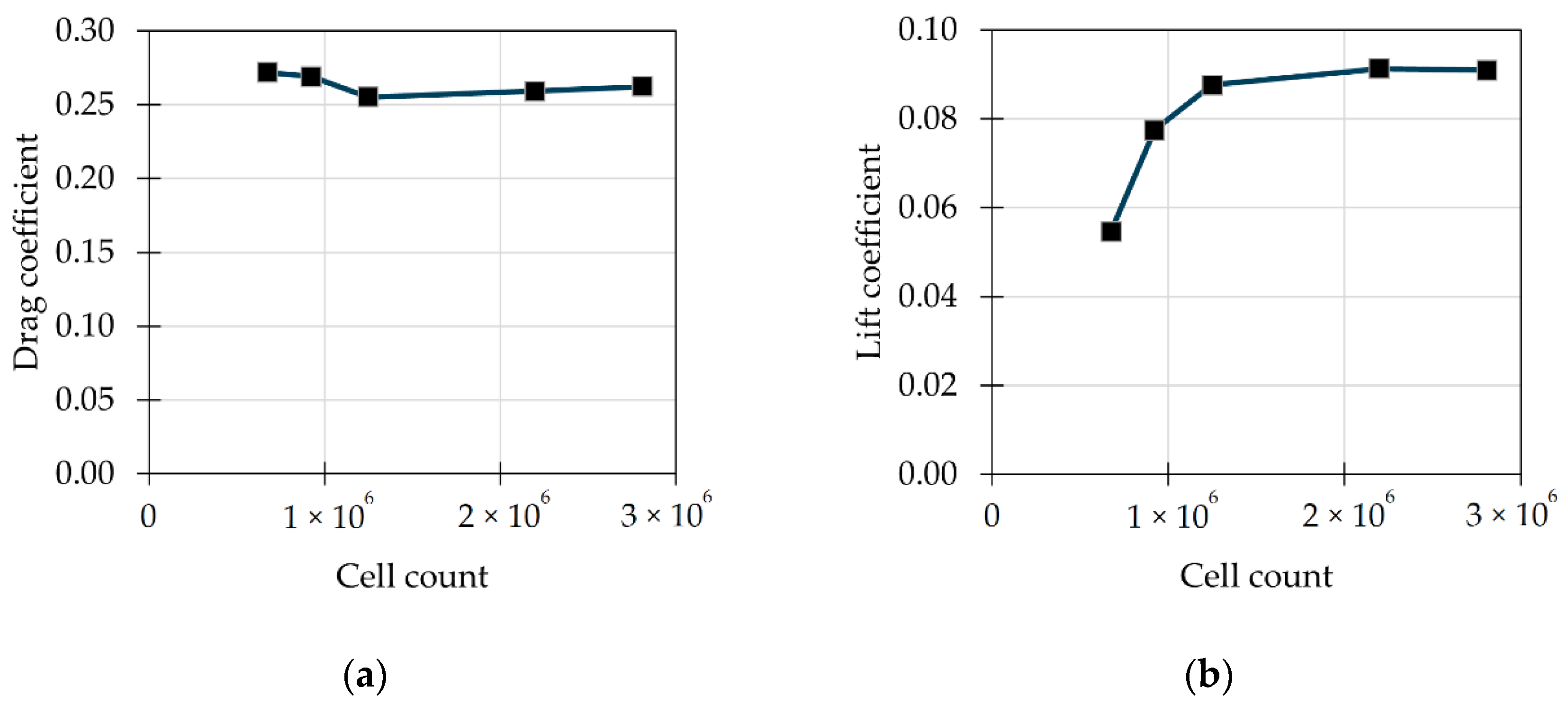
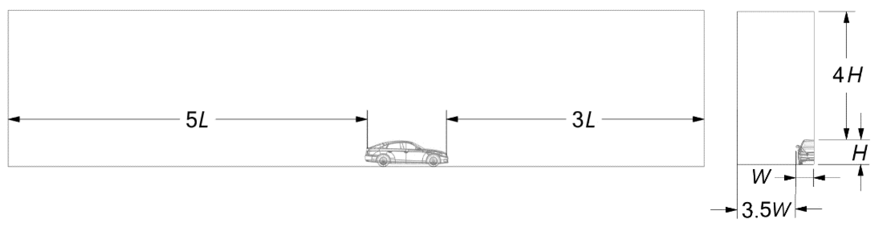
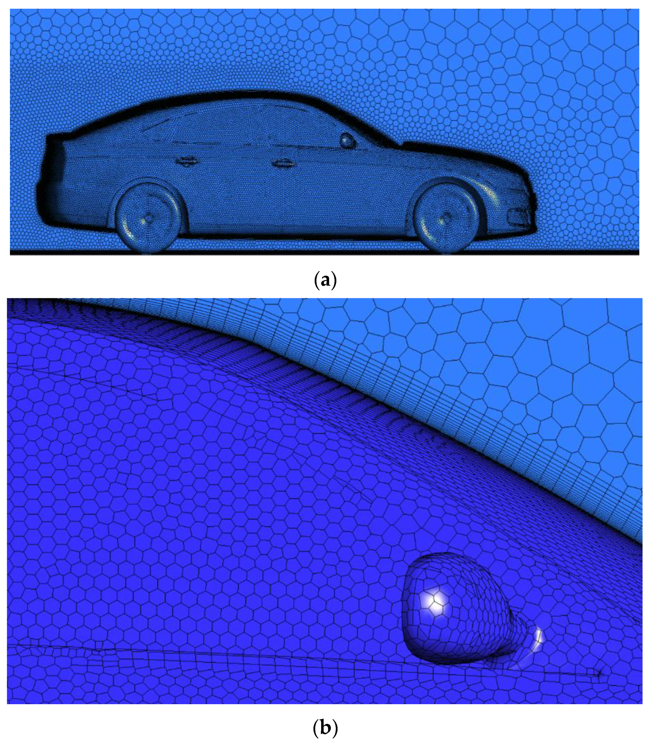
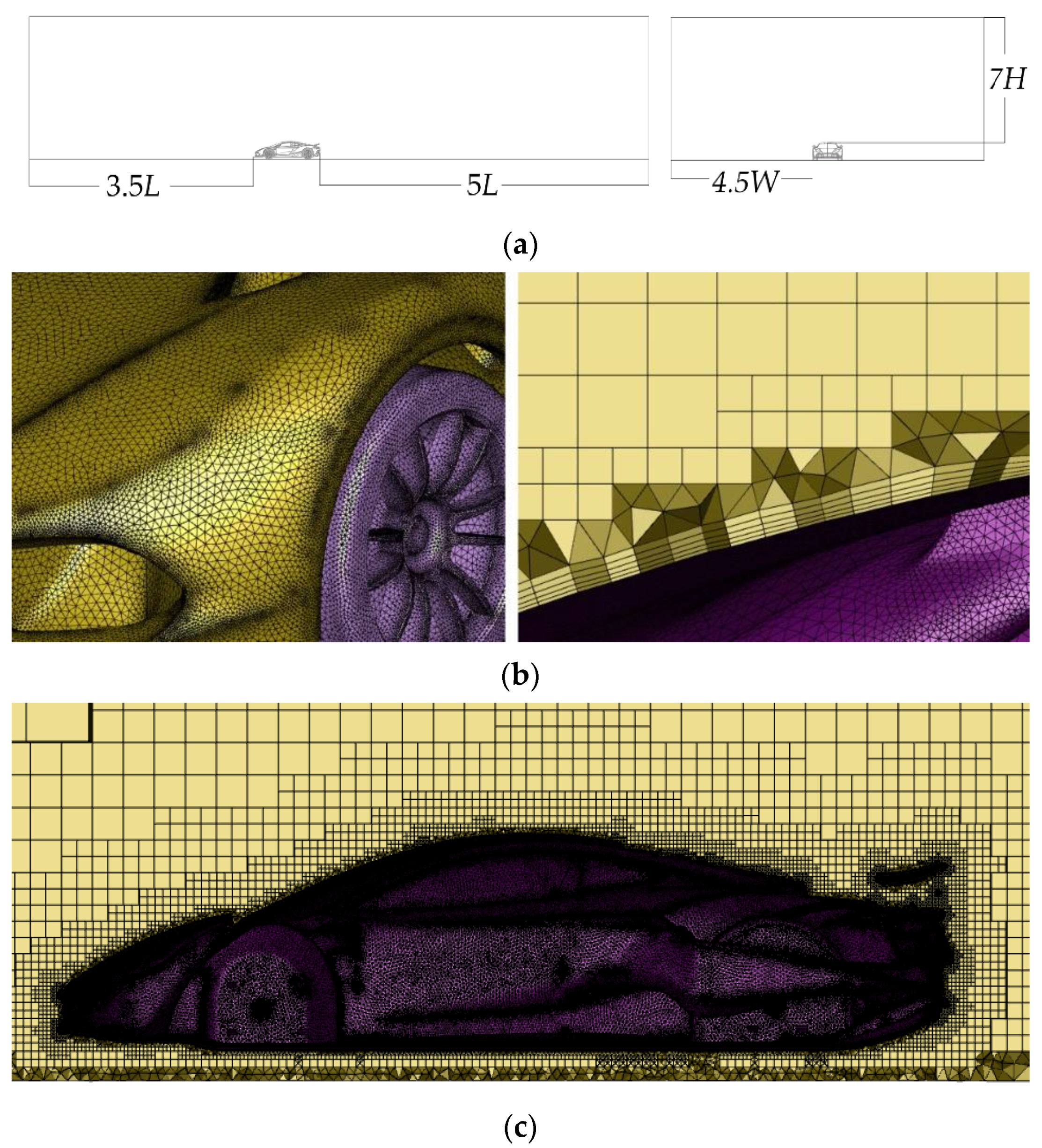
2.1. CFD Models
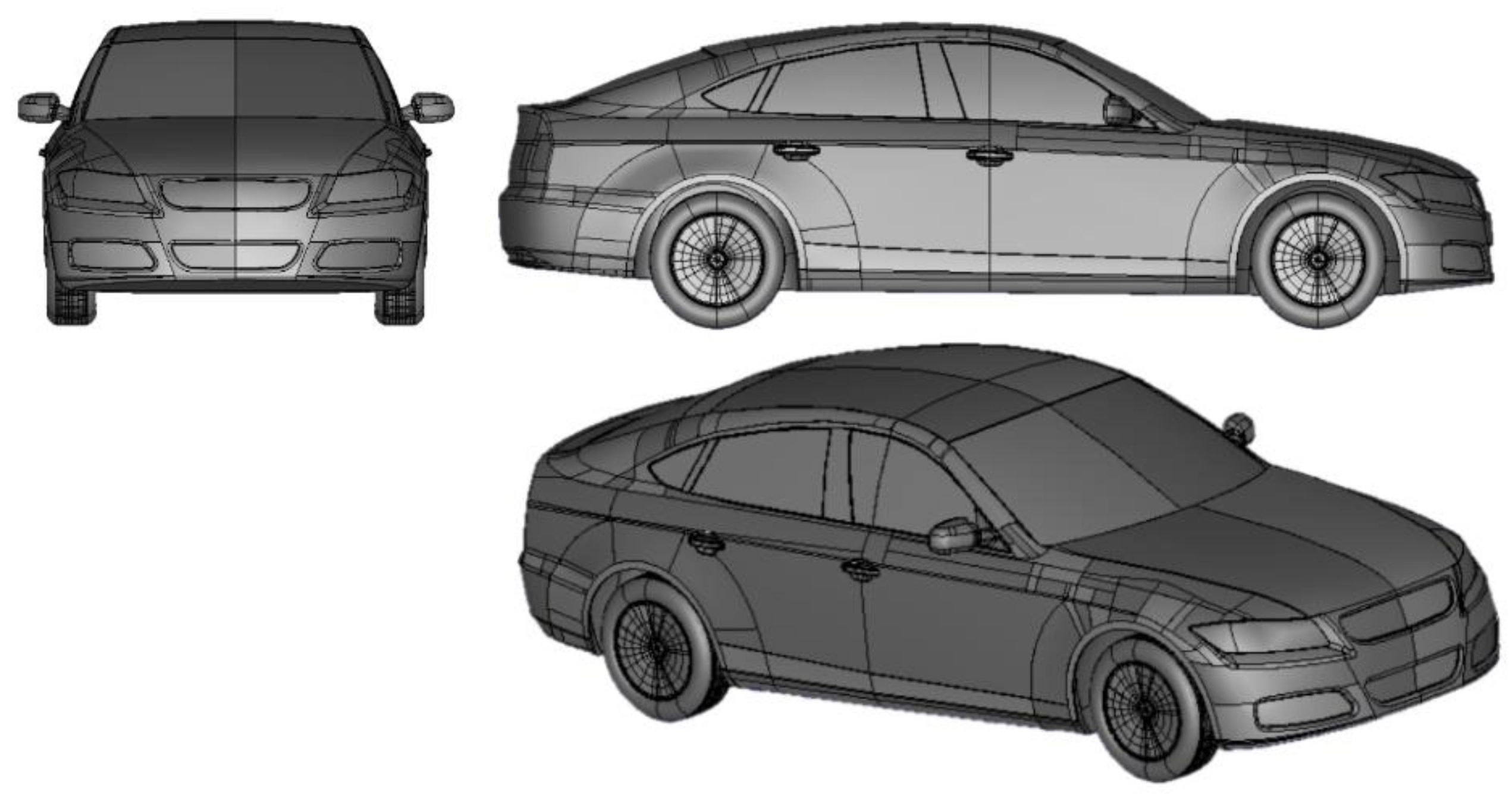
2.1.1. Passenger Car
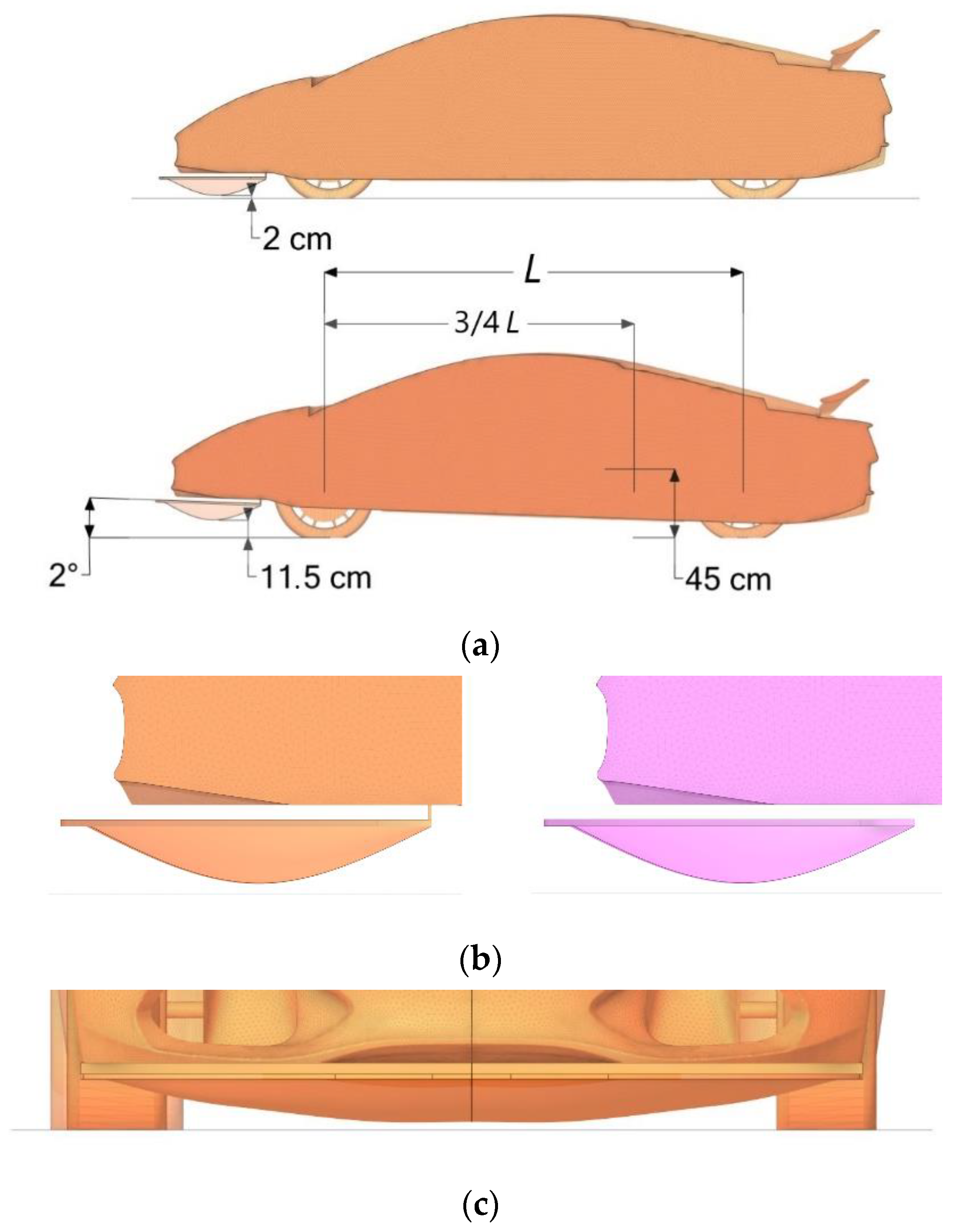
2.1.2. Sports Car
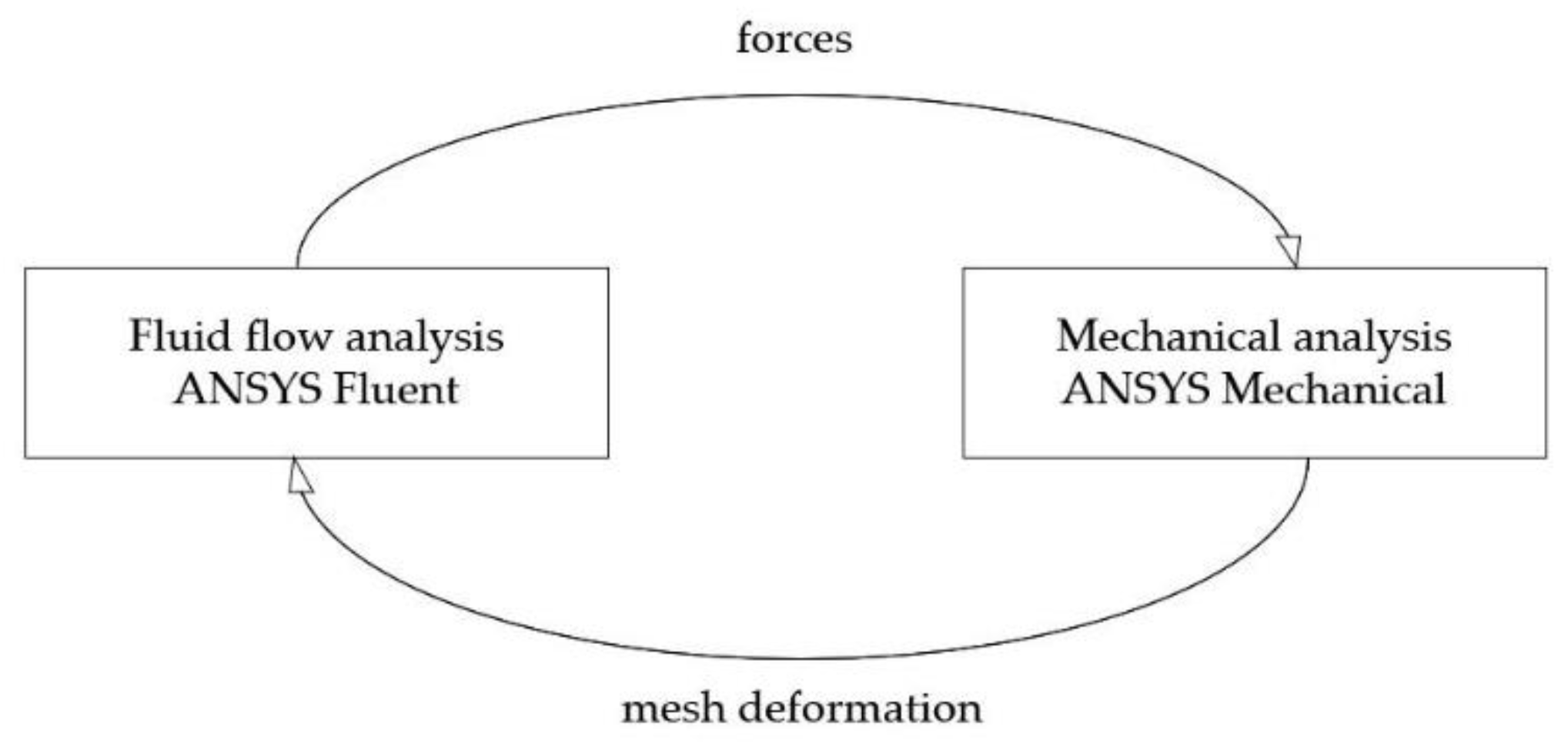
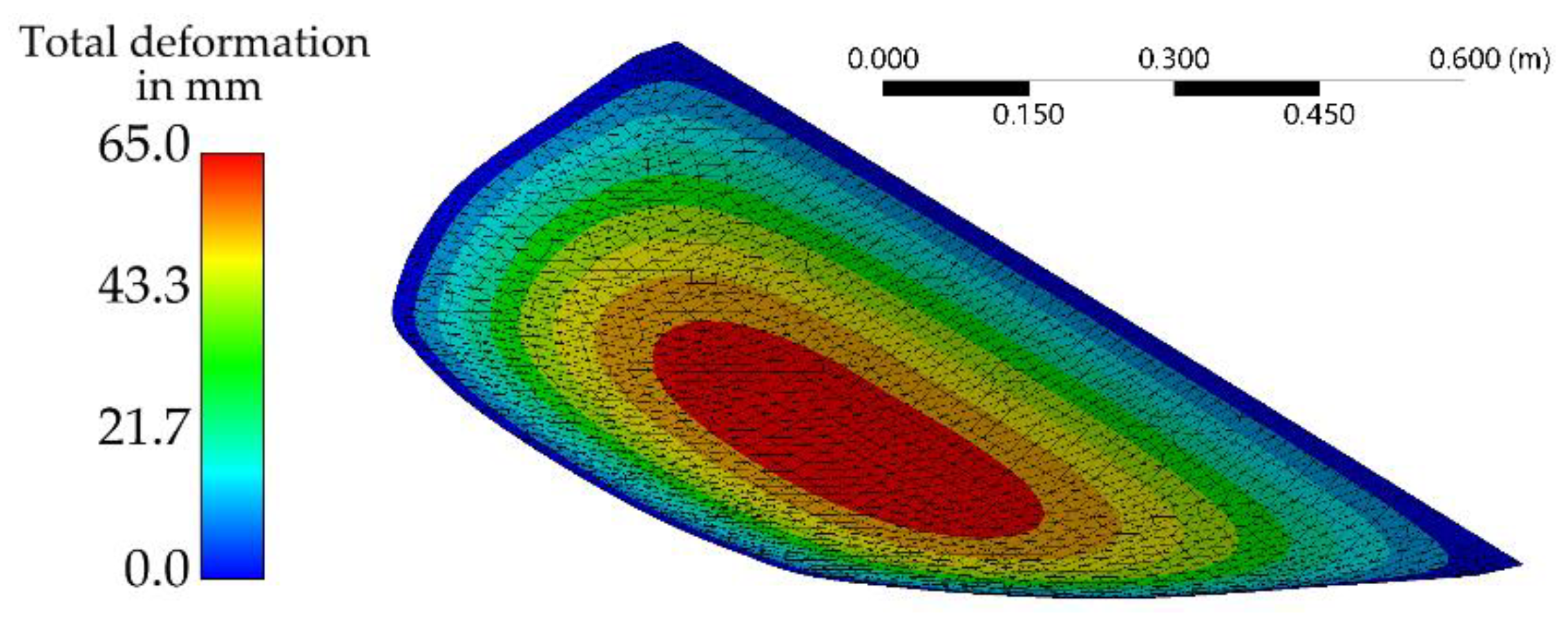
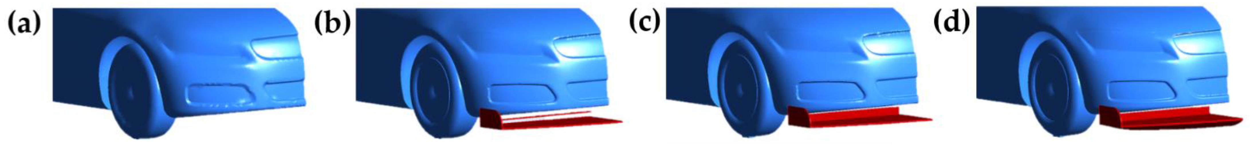
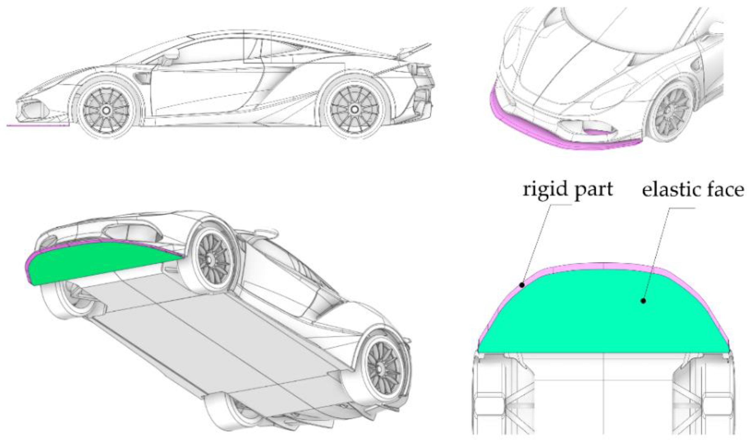
2.2. Flexible Splitter Model
3. Results
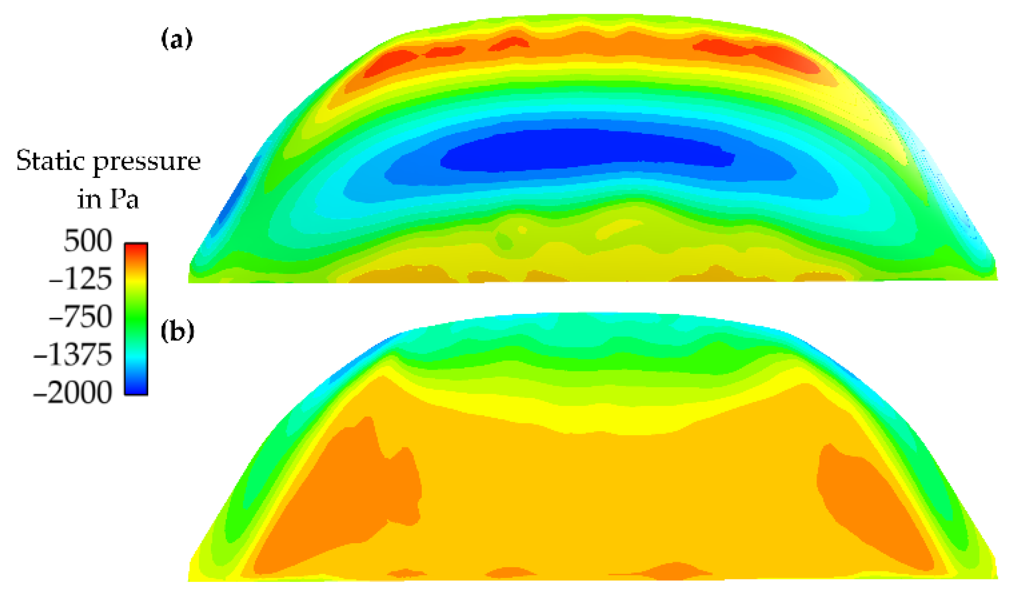
3.1. Inflatable Splitter
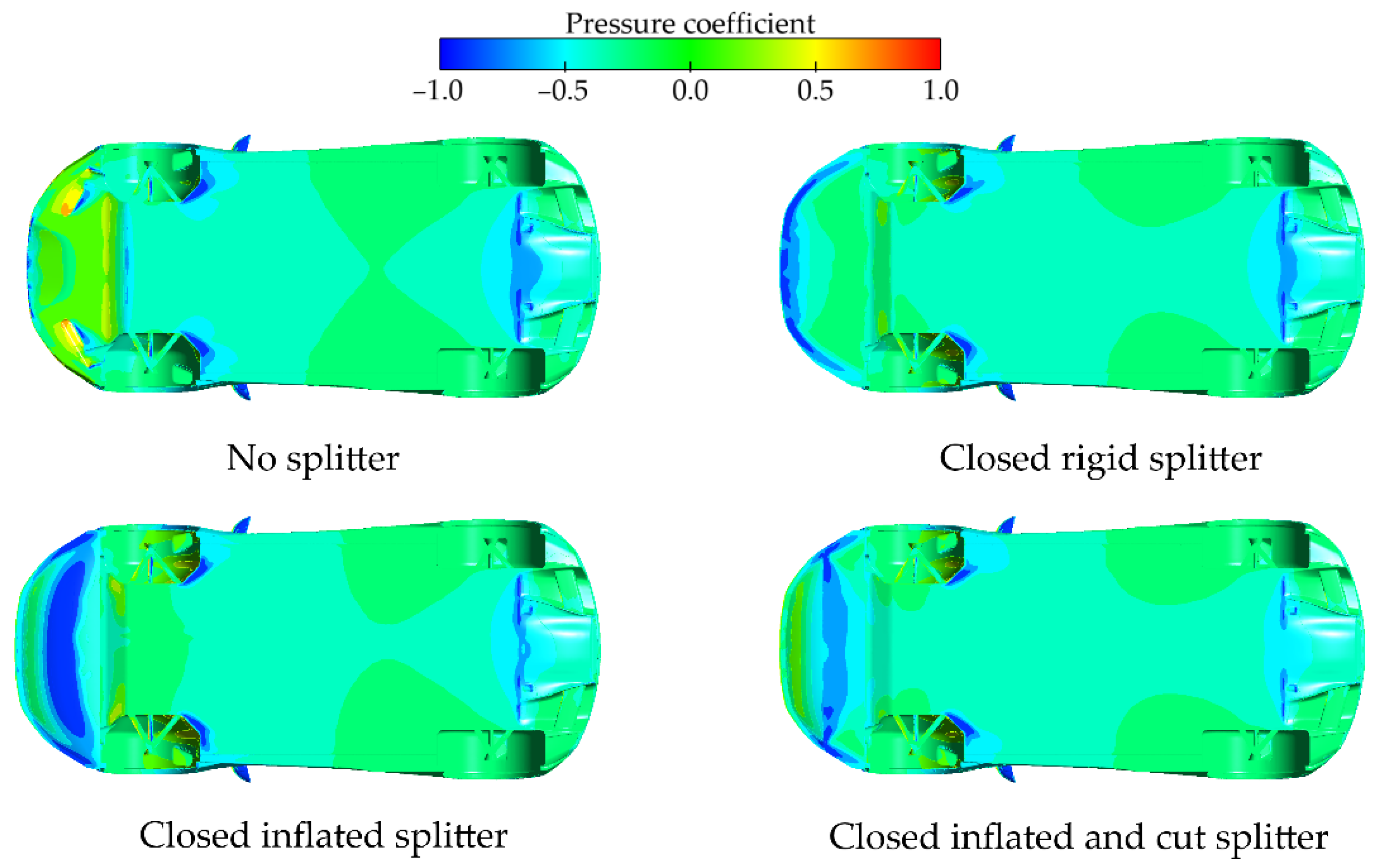
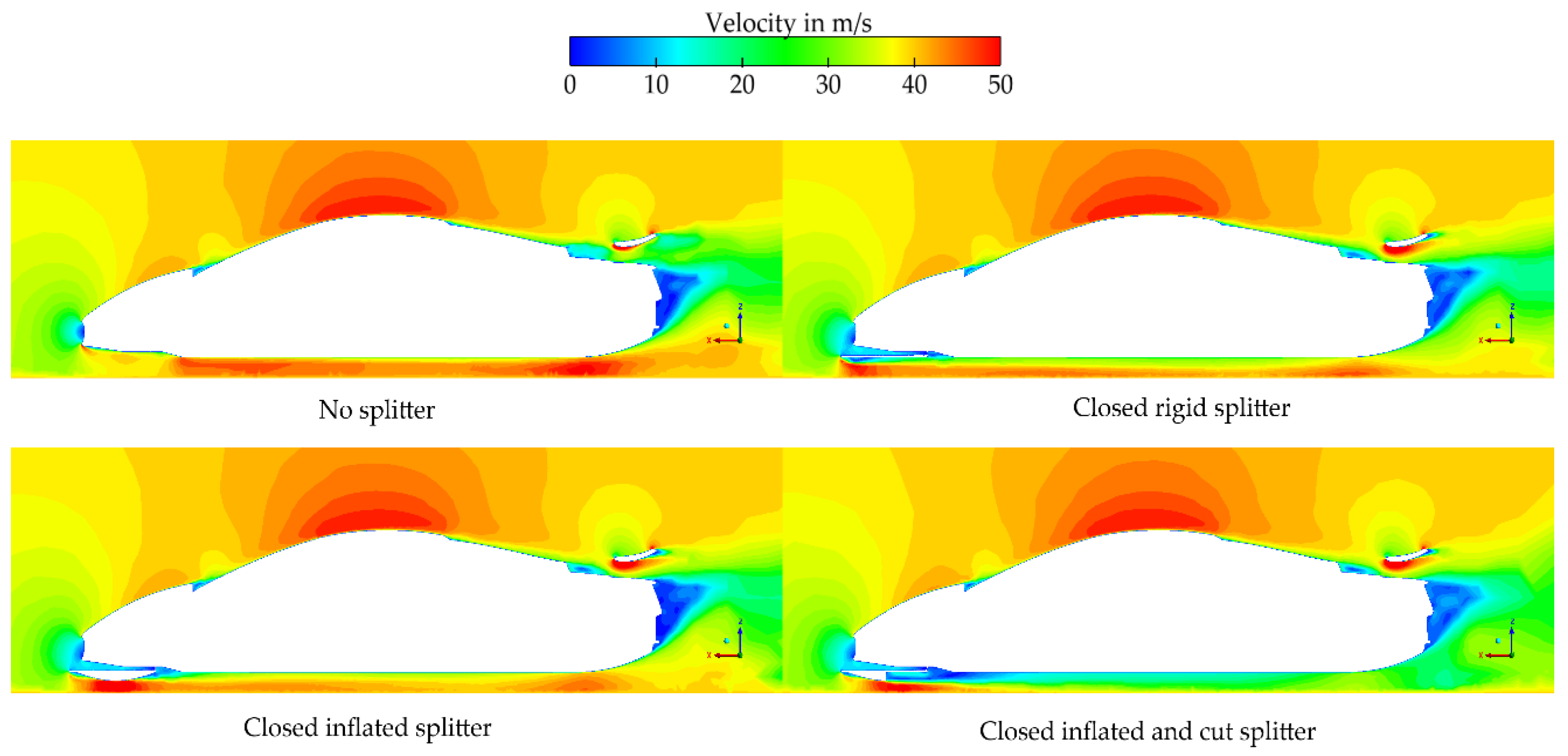
3.2. Passenger Car
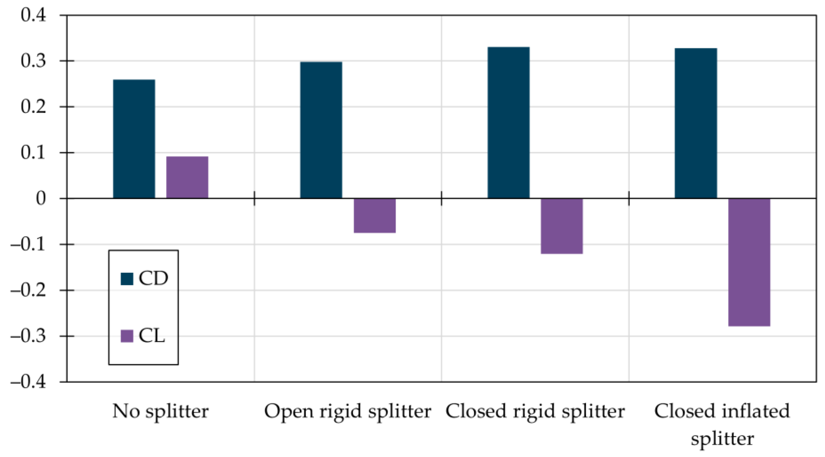
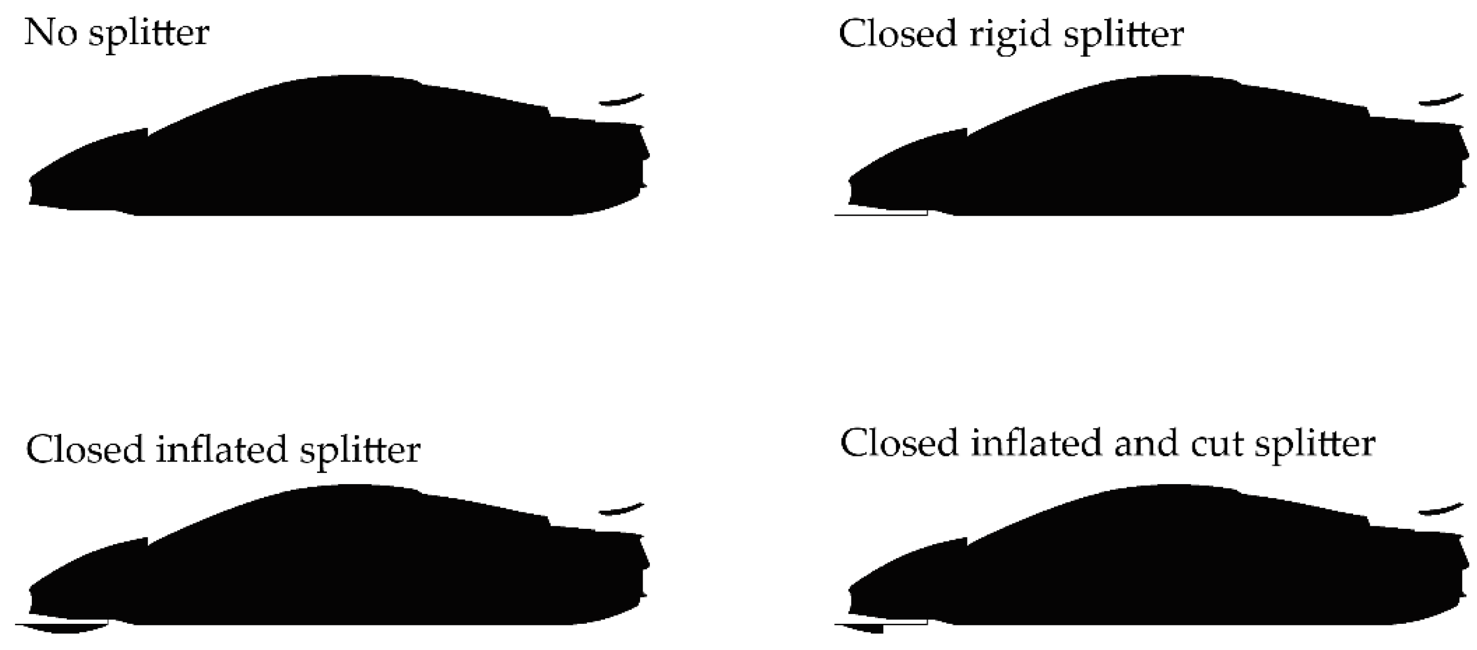
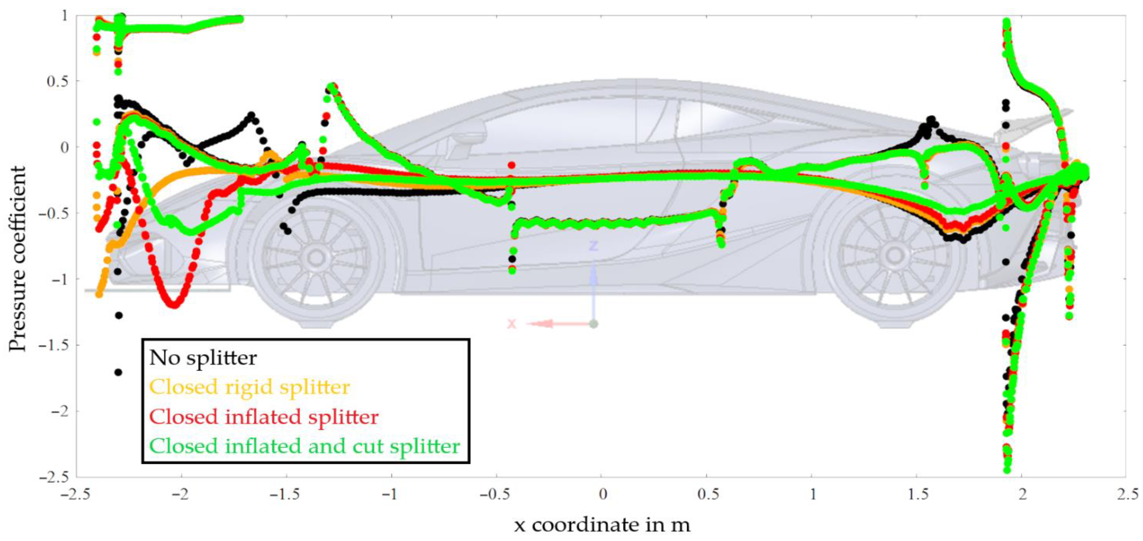
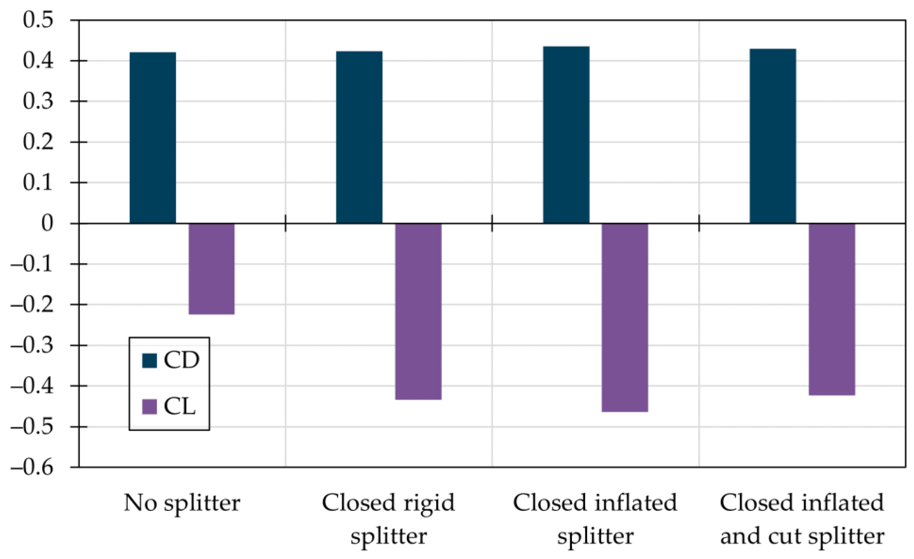
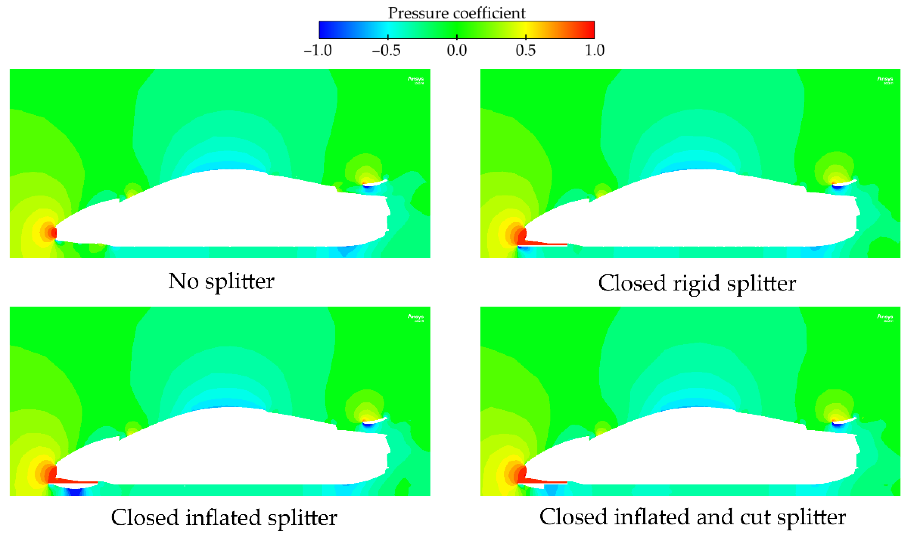
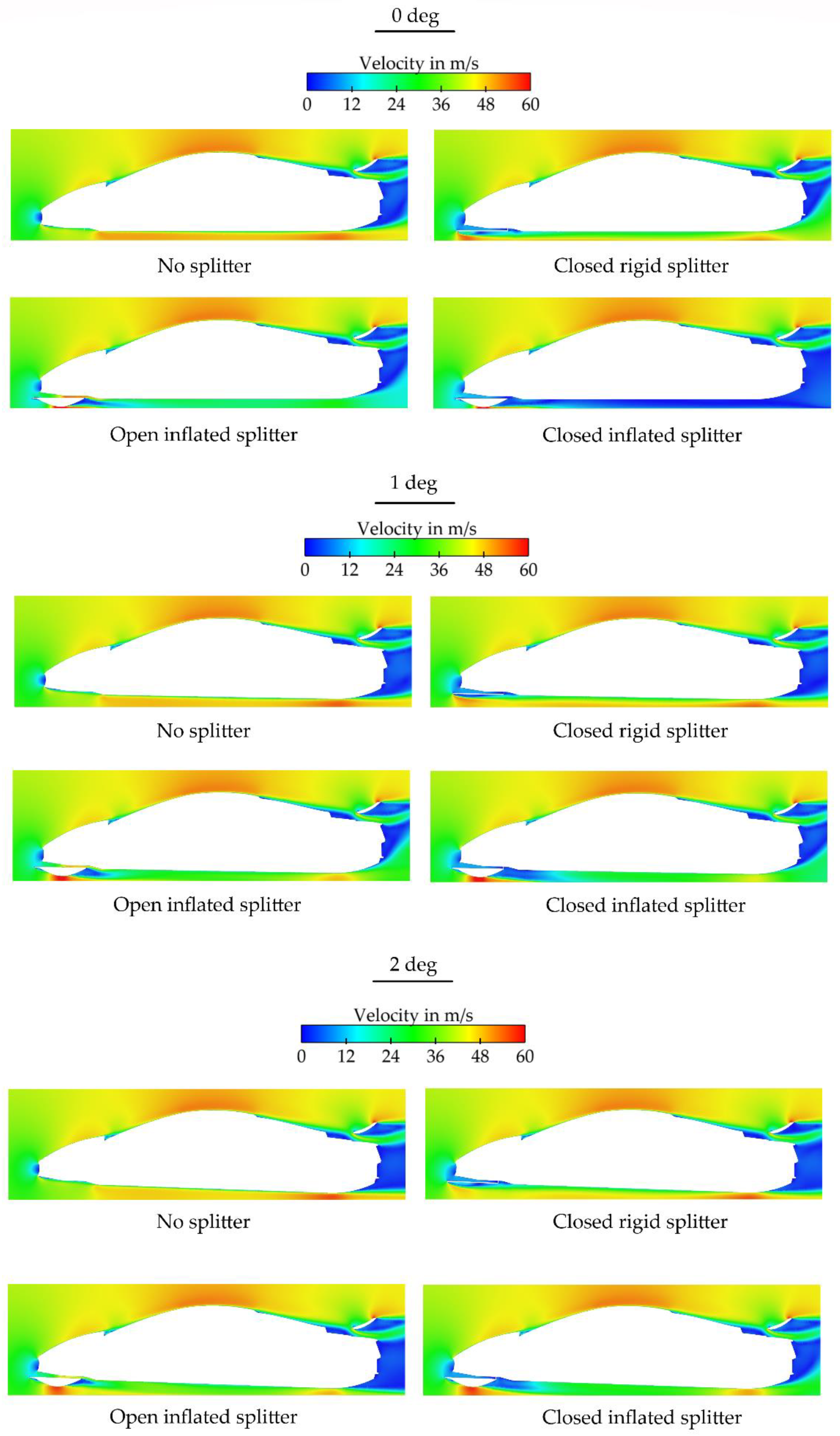
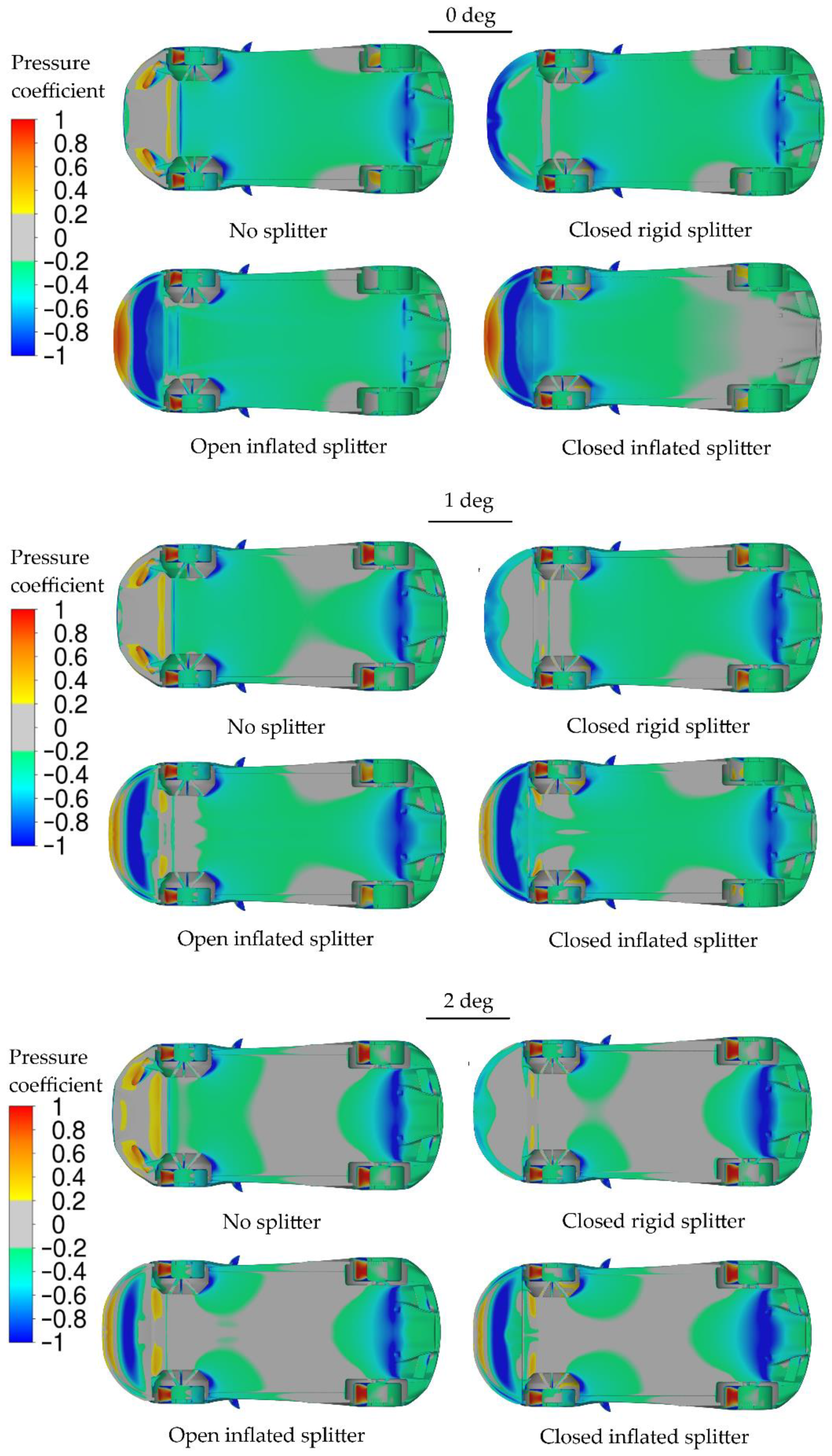
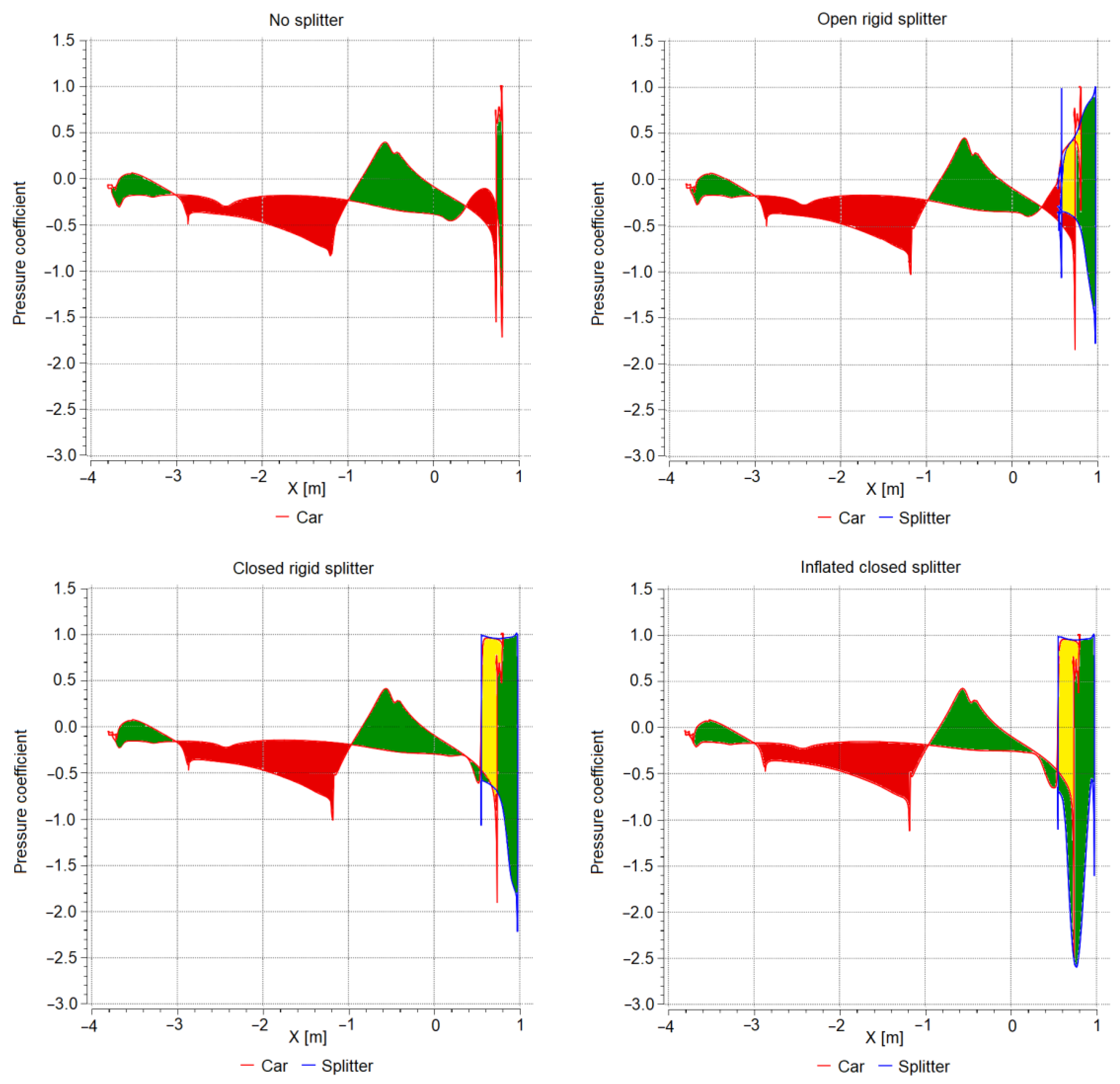
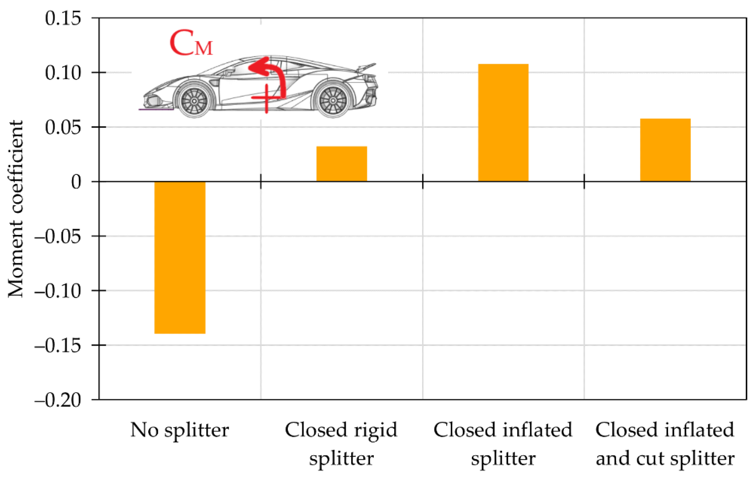
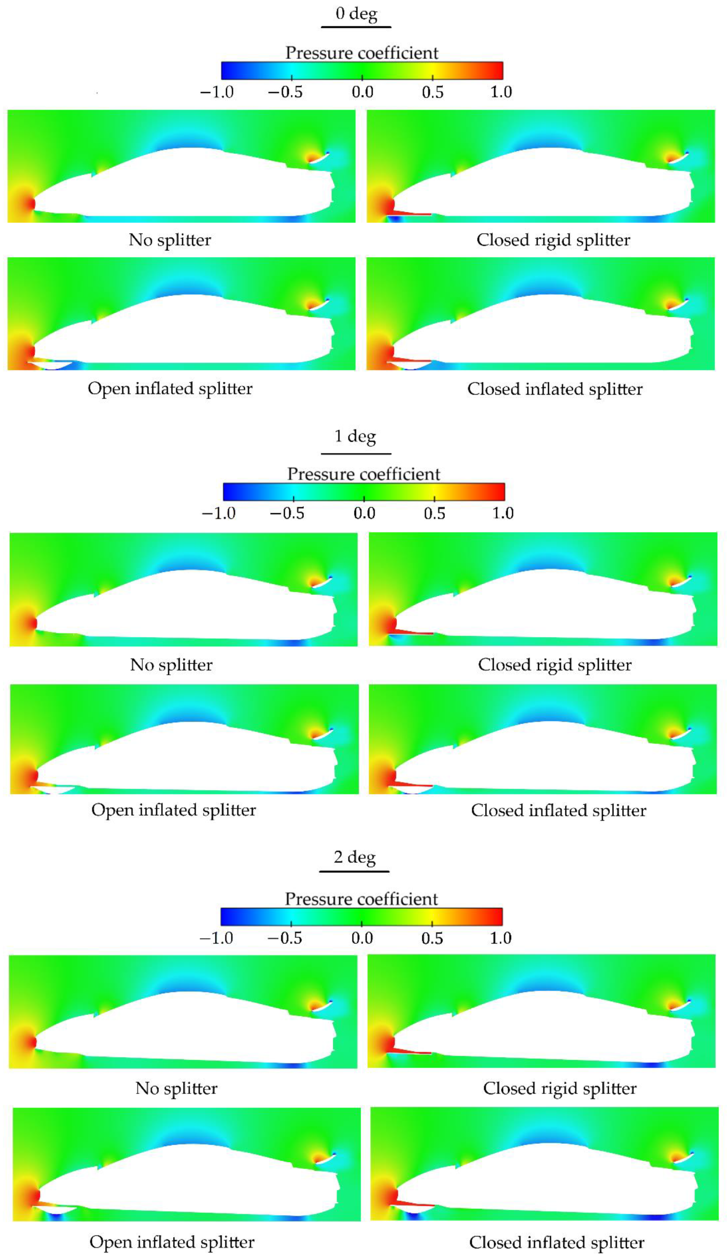
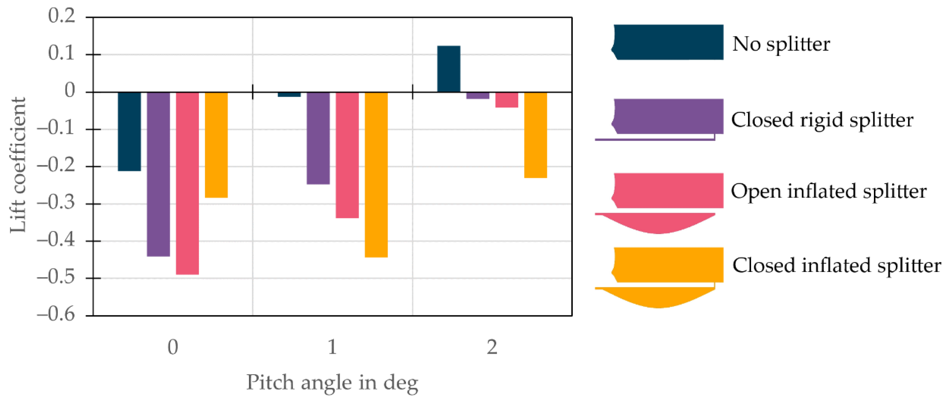
3.3. Sports Car
3.3.1. Zero Pitch Angle
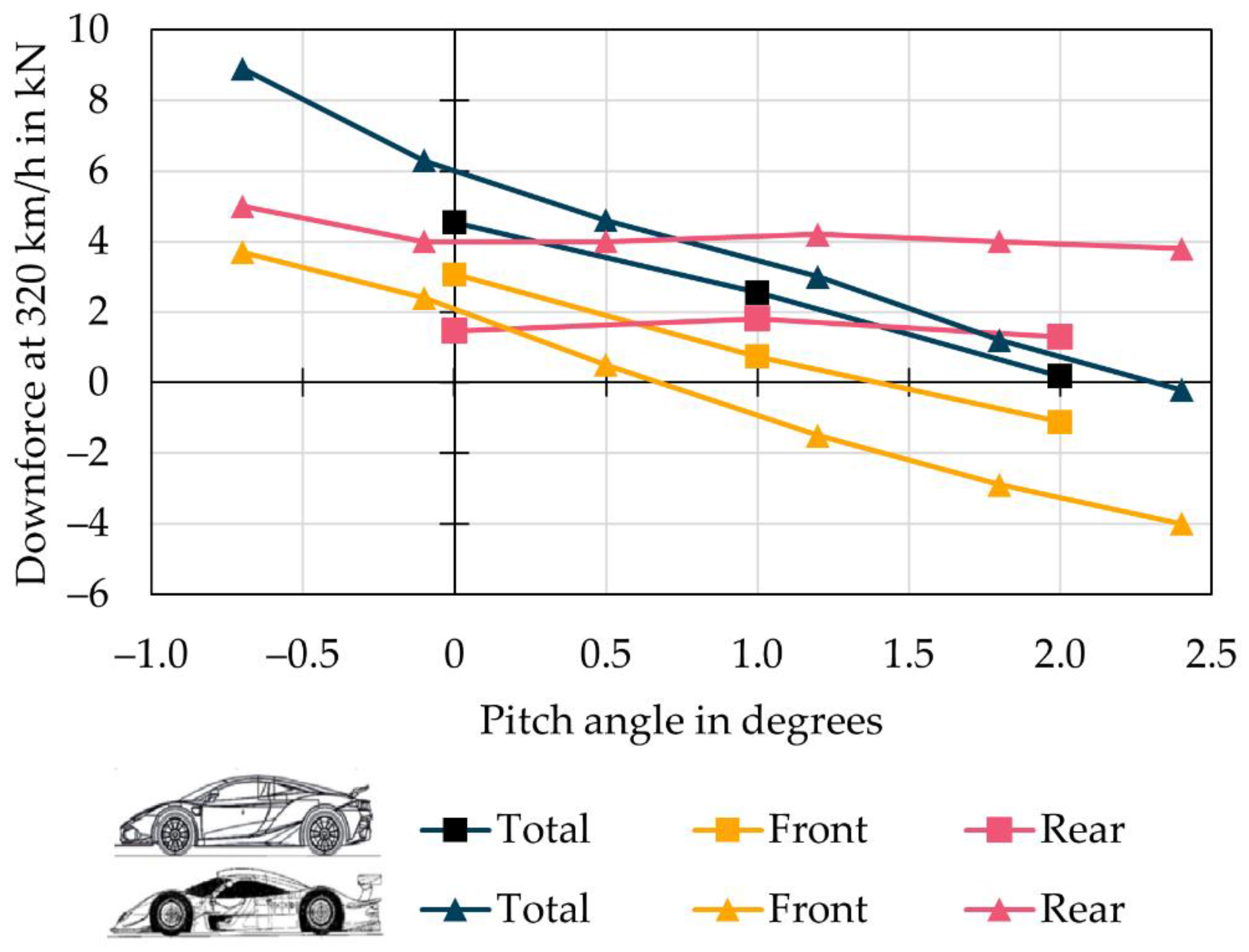
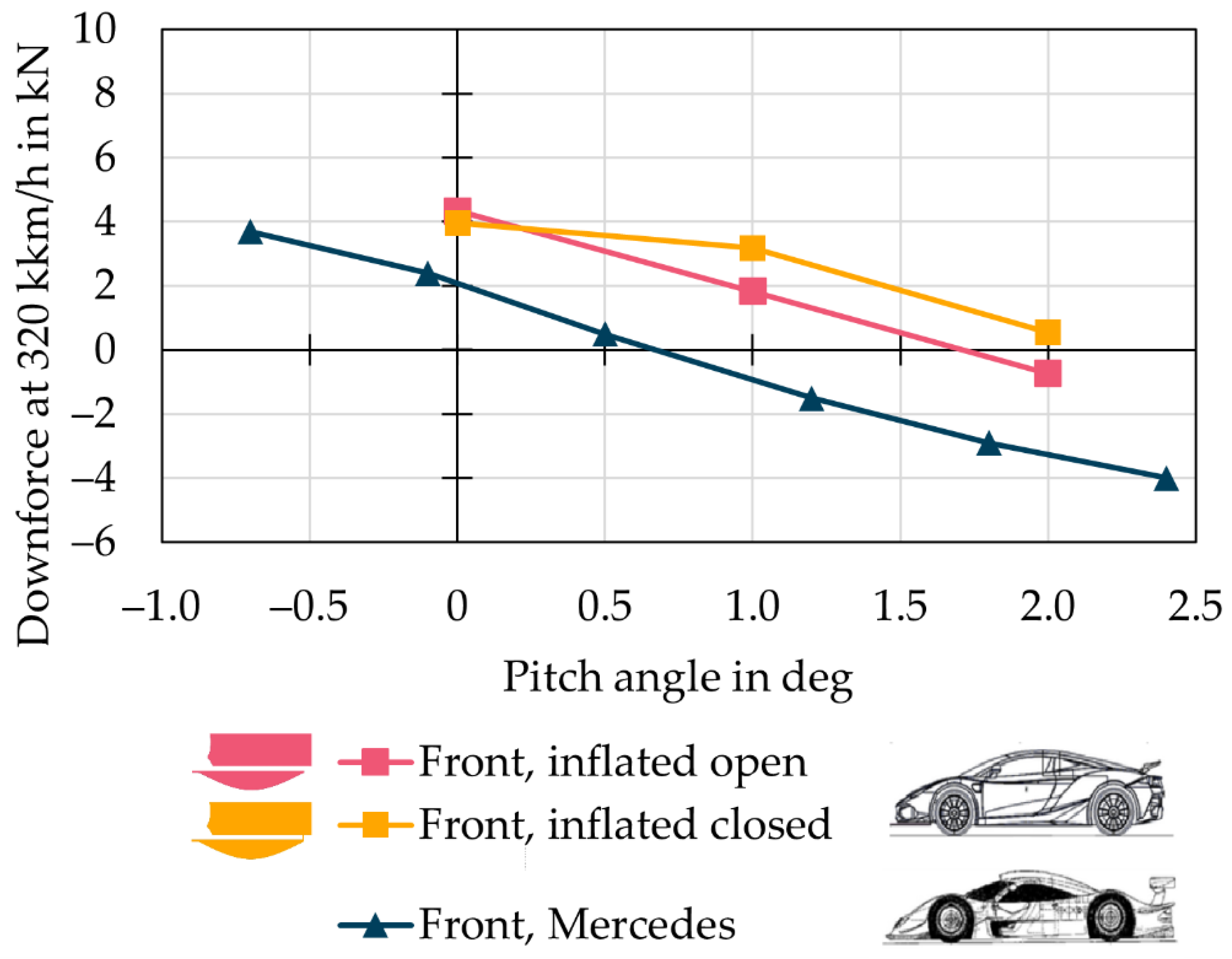
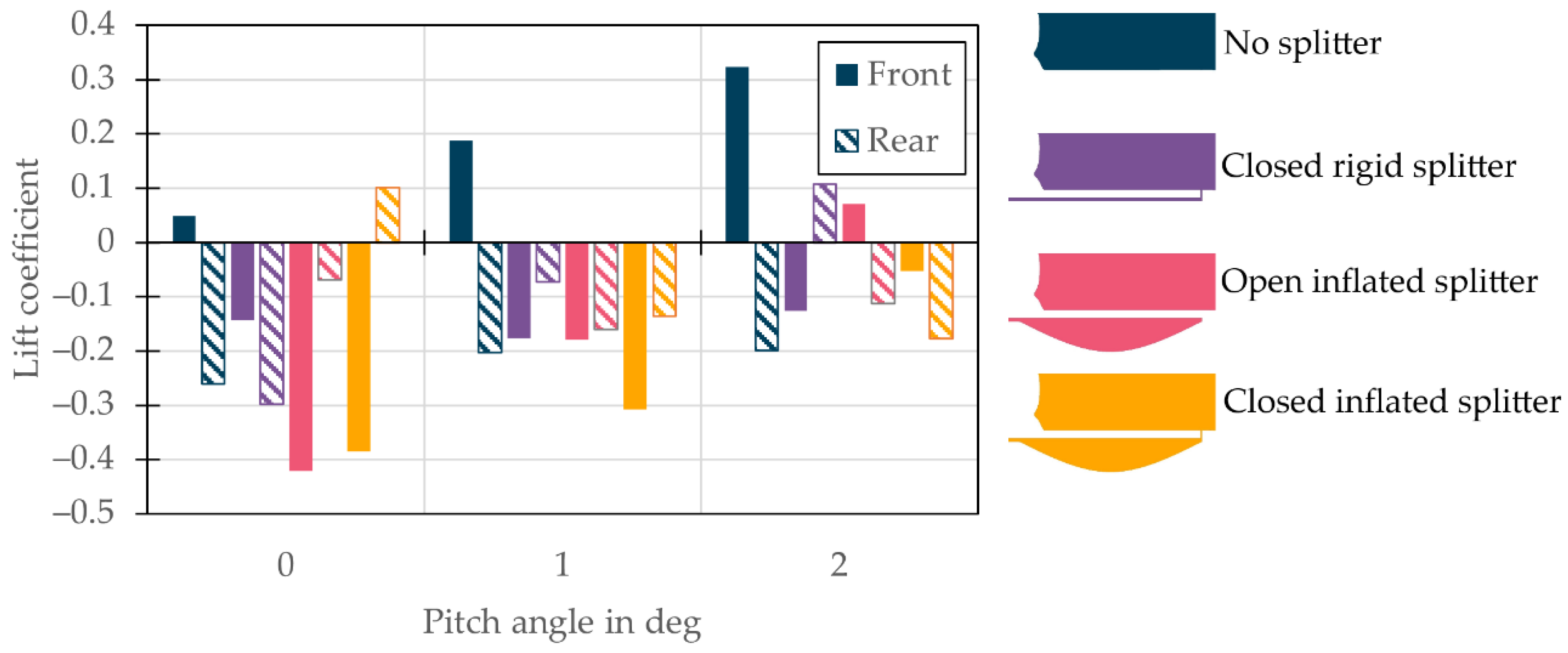
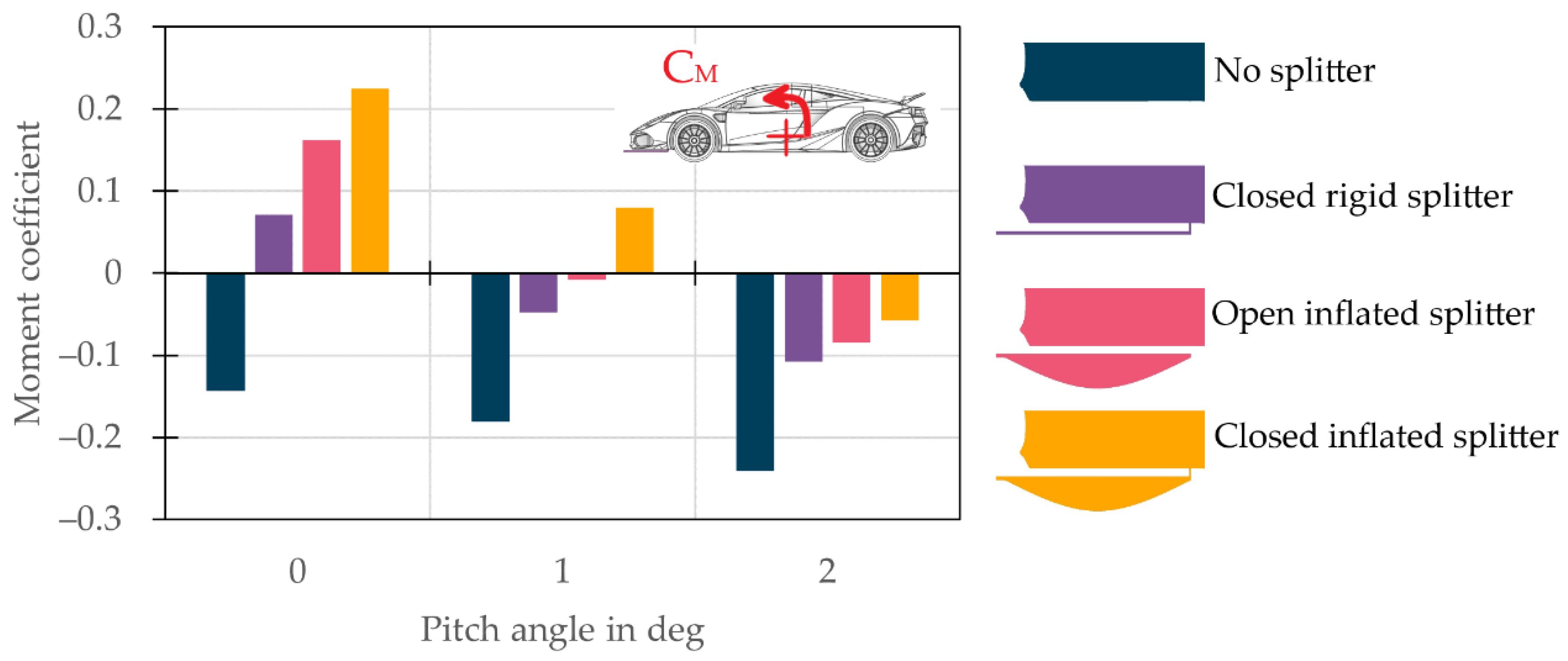
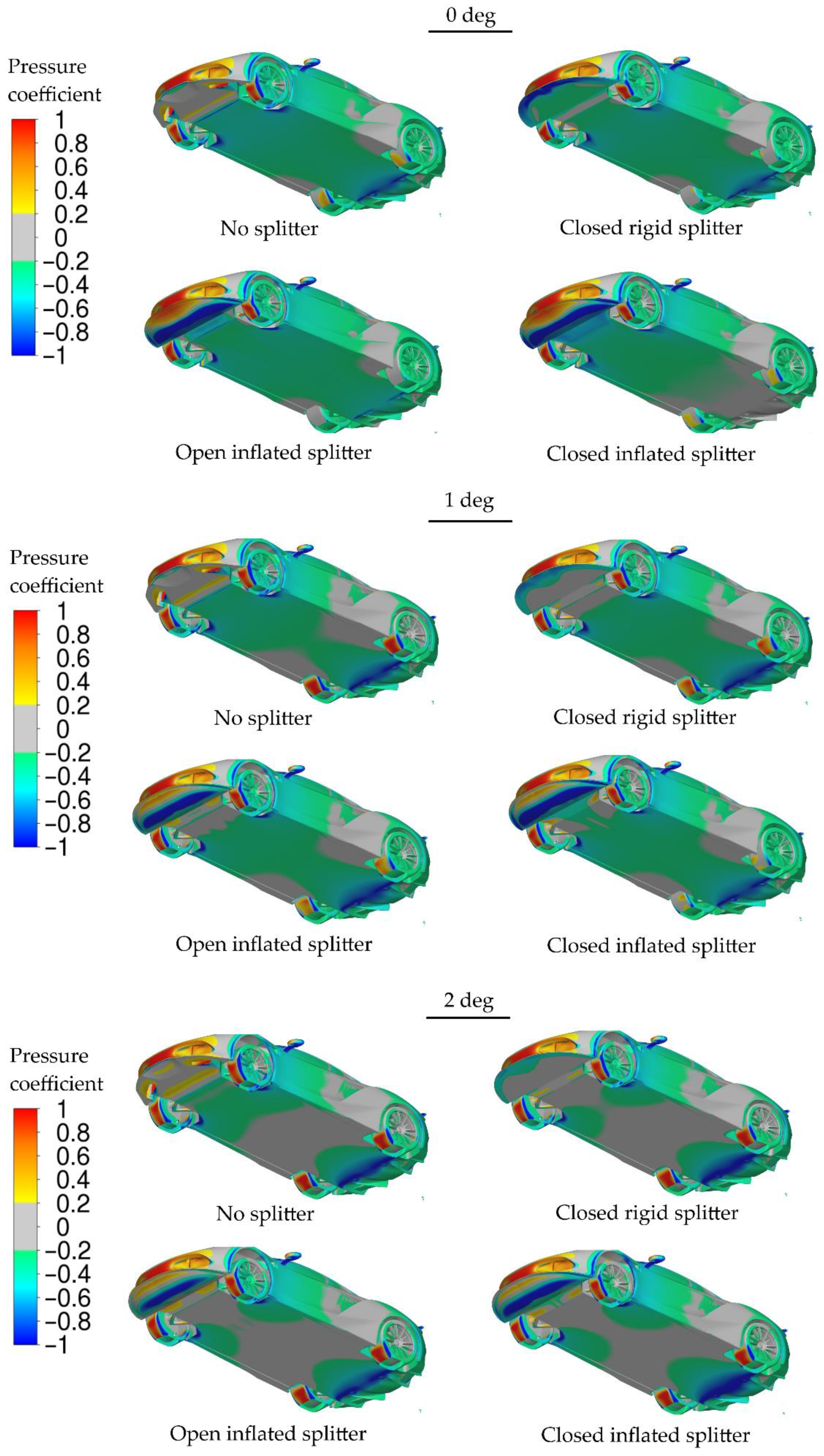
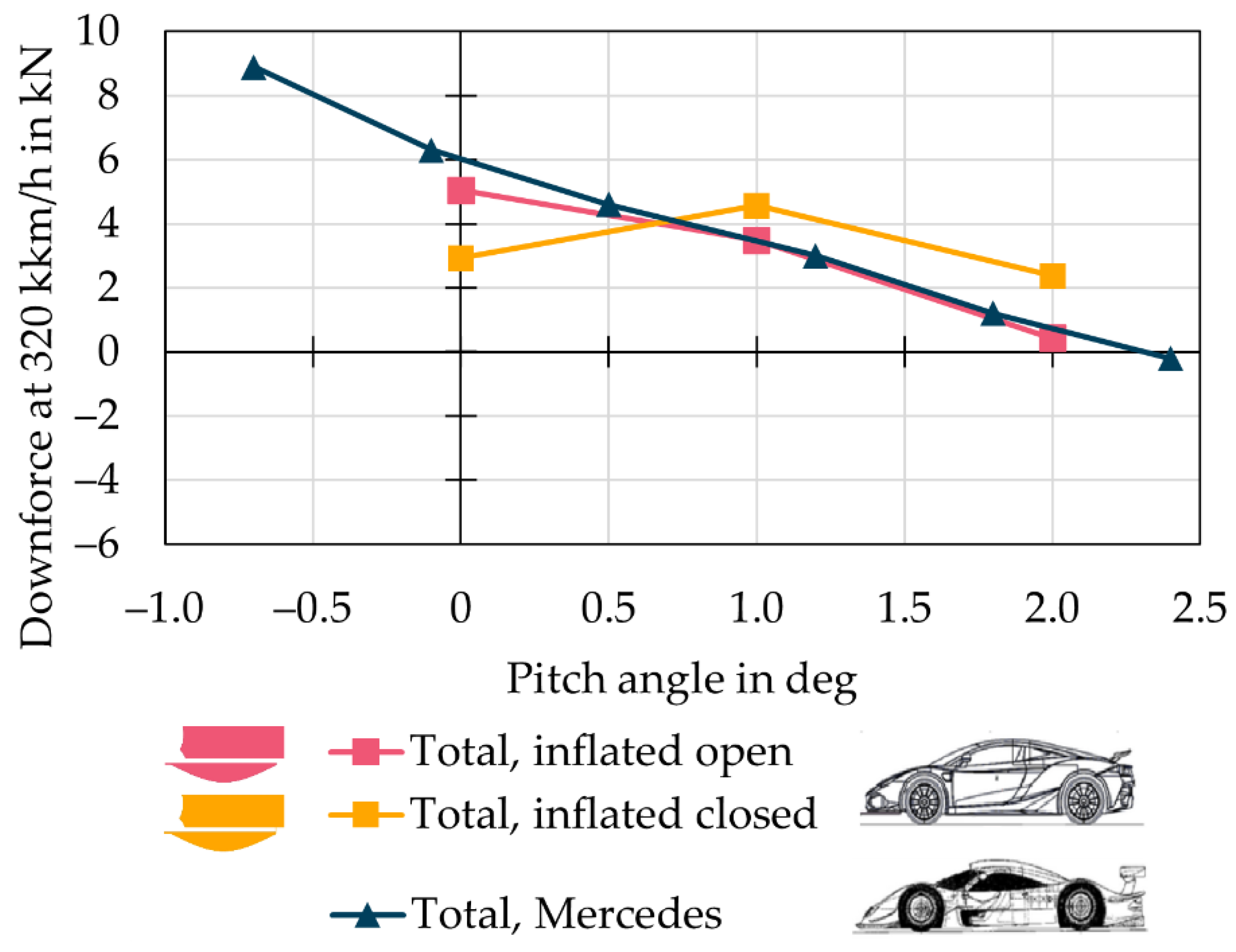
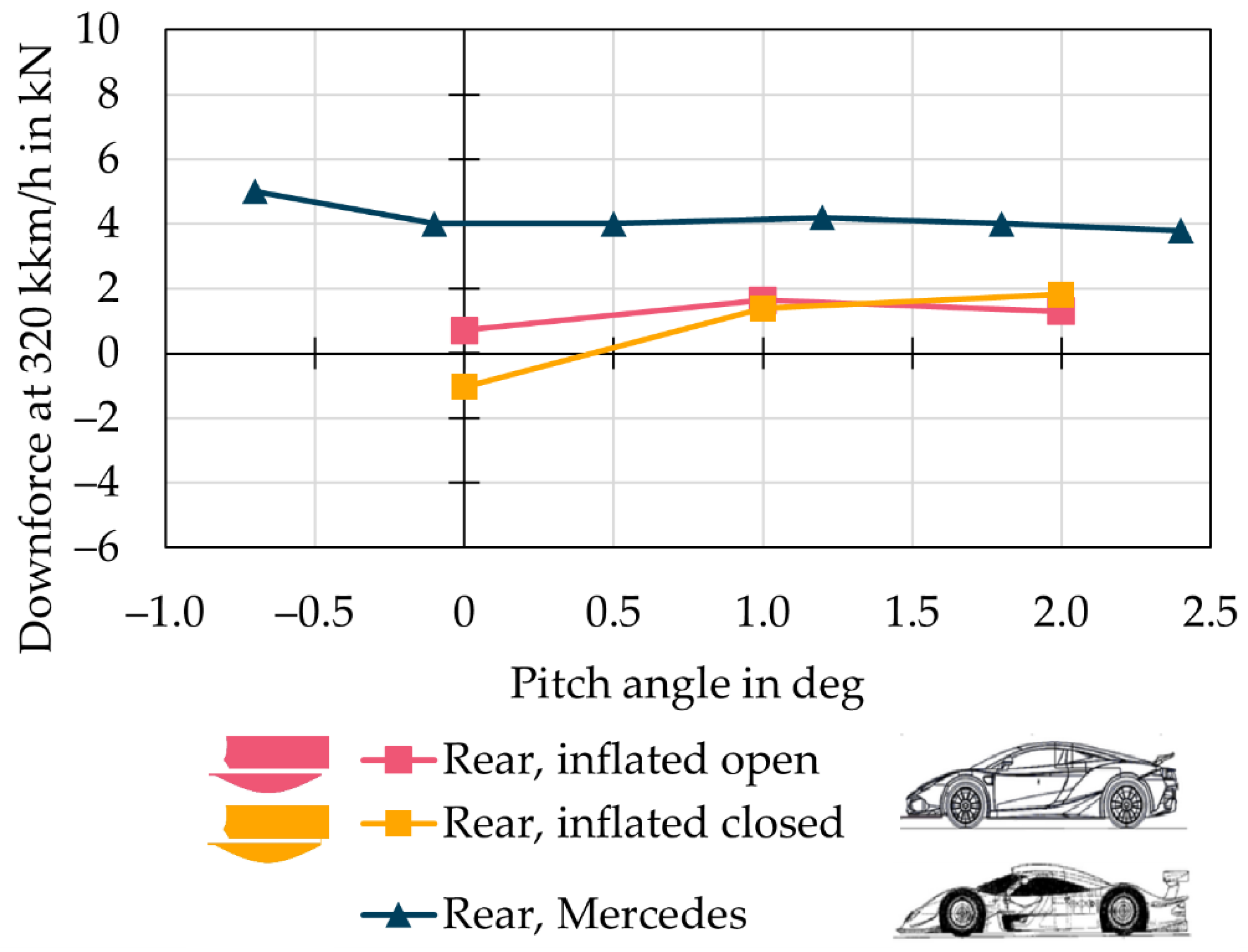
3.3.2. Nonzero Pitch Angle
4. Conclusions
Author Contributions
Funding
Data Availability Statement
Acknowledgments
Conflicts of Interest
Appendix A


References
- Milliken, W.F.; Milliken, D.L. Race Car Vehicle Dynamics; SAE International: Warrendale, PA, USA, 1995. [Google Scholar]
- Katz, J. Race Car Aerodynamics: Designing for Speed, 2nd ed.; Bentley (Robert) Inc.: Cambridge, MA, USA, 1996. [Google Scholar]
- Katz, J. Aerodynamics in motorsports. Proc. Inst. Mech. Eng. Part P J. Sports Eng. Technol. 2019, 235, 1–15. [Google Scholar] [CrossRef]
- Dominy, R.G. Aerodynamics of Grand Prix Cars. Proc. Inst. Mech. Eng. Part D J. Automob. Eng. 1992, 206, 267–274. [Google Scholar] [CrossRef]
- Porcar, L.; Toet, W.; Gamez-Montero, P.J. Study of the Effect of Vertical Airfoil Endplates on Diffusers in Vehicle Aerodynamics. Designs 2021, 5, 45. [Google Scholar] [CrossRef]
- Huminic, A.; Huminic, G. Aerodynamics of curved underbody diffusers using CFD. J. Wind Eng. Ind. Aerodyn. 2020, 205, 104300. [Google Scholar] [CrossRef]
- Guerrero, A.; Castilla, R.; Eid, G. A Numerical Aerodynamic Analysis on the Effect of Rear Underbody Diffusers on Road Cars. Appl. Sci. 2022, 12, 3763. [Google Scholar] [CrossRef]
- Ehirim, O.H.; Knowles, K.; Saddington, A.J. A review of ground-effect diffuser aerodynamics. J. Fluids Eng. 2019, 141, 1–19. [Google Scholar] [CrossRef]
- Zhang, X.; Toet, W.; Zerihan, J. Ground effect aerodynamics of race cars. Appl. Mech. Rev. 2006, 59, 33–49. [Google Scholar] [CrossRef] [Green Version]
- McBeath, S. Competition Car Aerodynamics, 3rd ed.; Veloce Publishing: Dorchester/Poundbury, UK, 2017. [Google Scholar]
- Piechna, J. A Review of Active Aerodynamic Systems for Road Vehicles. Energies 2021, 14, 7887. [Google Scholar] [CrossRef]
- Szudarek, M.; Piechna, J. CFD Analysis of the Influence of the Front Wing Setup on a Time Attack Sports Car’s Aerodynamics. Energies 2021, 14, 7907. [Google Scholar] [CrossRef]
- Wright, P. Cleared for take-off. Racecar Eng. 1999, 9, 16–18. [Google Scholar]
- Dominy, R.G.; Ryan, A.; Sims-Williams, D.B. The aerodynamic stability of a Le Mans prototype race car under off-design pitch conditions. SAE Trans. 2000, 109, 1454–1460. [Google Scholar]
- Katz, J.; Garcia, D.; Sluder, R. Aerodynamics of Race Car Liftoff; SAE Technical Paper Series; SAE International: Warrendale, PA, USA, 2004. [Google Scholar] [CrossRef]
- Porsche GT1 Yannick Dalmas Road Atlanta Crash. Available online: https://www.youtube.com/watch?v=NTSdaILo4L4 (accessed on 31 June 2022).
- Gullberg, P.; Löfdahl, L. The Role of Aerodynamics in the 1955 Le Mans Crash; SAE Technical Paper 2008-01-2996; SAE International: Warrendale, PA, USA, 2008. [Google Scholar] [CrossRef]
- Kataoka, T.; China, H.; Nakagawa, K.; Yanagimoto, K.; Yoshida, M. Numerical simulation of road vehicle aerodynamics and effect of aerodynamic devices. SAE Trans. 1991, 100, 722–734. [Google Scholar]
- Santer, R.; Gleason, M.E. The Aerodynamic Development of the Probe IV Advanced Concept Vehicle; SAE Technical Paper Series; SAE International: Warrendale, PA, USA, 1983; p. 831000. [Google Scholar] [CrossRef]
- Estrada, G. Mercedes-AMG GTR: Aerodynamics for the Record. In Proceedings of the Progress in Vehicle Aerodynamics and Thermal Management, 11th FKFS Conference, Stuttgart, Germany, 26–27 September 2017; pp. 135–144. [Google Scholar] [CrossRef]
- Meder, J.; Wiegand, T.; Pfadenhauer, M. Adaptive aerodynamics of the new Porsche 911 Turbo. ATZ Worldw. 2014, 116, 42–45. [Google Scholar] [CrossRef]
- Bhattacharjee, S.; Arora, B.; Kashyap, V. Optimization of Race Car Front Splitter Placement Using CFD; SAE Technical Paper 2019-01-5097; SAE International: Warrendale, PA, USA, 2019. [Google Scholar] [CrossRef]
- Cupis, D.D.; Carvalho Pinheiro, H.D.; Ferraris, A.; Airale, A.G.; Carello, M. Active Aerodynamics Design Methodology for Vehicle Dynamics Enhancement. In Proceedings of the International Conference of IFToMM ITALY, Naples, Italy, 9–11 September 2020; Springer: Cham, Switzerland, 2020; pp. 777–785. [Google Scholar]
- Yasui, T.; Murata, O. The Effect of a Moving Ground and Rotating Wheels on Transient Aerodynamic Properties of a Car Model in Pitching Motion. Trans. Soc. Automot. Eng. Jpn. 2021, 52, 808–813. [Google Scholar]
- Braking Bag a Braking Parachute for the Car. Available online: https://500sec.com/braking-bag/ (accessed on 20 July 2022).
- DrivAer Model. Available online: https://www.epc.ed.tum.de/en/aer/research-groups/automotive/drivaer/ (accessed on 31 June 2022).
- Ashton, N.; Revell, A. Comparison of RANS and DES Methods for the Drivaer Automotive Body; SAE Technical Paper 2015-01-1538; SAE International: Warrendale, PA, USA, 2015. [Google Scholar] [CrossRef]
- Lanfrit, M. Best Practice Guidelines for Handling Automotive External Aerodynamics with FLUENT Version 1.2. 2005. Available online: https://www.southampton.ac.uk/~nwb/lectures/GoodPracticeCFD/Articles/Ext_Aero_Best_Practice_Ver1_2.pdf (accessed on 20 July 2022).
- Piechna, J.R.; Kurec, K.; Broniszewski, J.; Remer, M.; Piechna, A.; Kamieniecki, K.; Bibik, P. Influence of the Car Movable Aerodynamic Elements on Fast Road Car Cornering. Energies 2022, 15, 689. [Google Scholar] [CrossRef]
- Tudruj, S.; Piechna, J. New model of the simulation of the airbag operation in the case of the out-of-position occupant–the comparison with existing models. Arch. Mech. Eng. 2003, 2, 201–223. [Google Scholar]
- Tudruj, S.; Piechna, J.; Dziewoński, T. Influence of the Outside Inertia Effect on Airbag Deployment; IRCOBI: Gratz, Austria, 2004; pp. 339–340. [Google Scholar]
- Tudruj, S.; Piechna, J. Numerical Analysis of the Possibility of Using an External Air Bag to Protect a Small Urban Vehicle during a Collision. Arch. Mech. Eng. 2012, 59, 257–281. [Google Scholar] [CrossRef] [Green Version]
- Harper, C. Handbook of Plastics, Elastomers, and Composites; McGraw-Hill Education: New York, NY, USA, 2002. [Google Scholar]


| Experiment | Simulation, k-Omega SST | This Work, Simulation k-Omega BSL | |
|---|---|---|---|
| Drag coefficient | 0.254 | 0.260 | 0.259 |
| Closed Rigid Splitter, High Mount | Closed Inflated Splitter, High Mount | |
|---|---|---|
| Drag coefficient | 0.30 | 0.29 |
| Lift coefficient | 0.00 | −0.01 |
| Splitter Variant | CD | CL | CM |
|---|---|---|---|
| No splitter | 0.421 | −0.224 | −0.139 |
| Closed rigid splitter | 0.424 | −0.434 | 0.032 |
| Closed inflated splitter | 0.435 | −0.464 | 0.108 |
| Closed inflated and cut splitter | 0.429 | −0.423 | 0.058 |
| Splitter | Pitch Angle in Degrees | CD | CL | CLf | CLr | CM |
|---|---|---|---|---|---|---|
| None | 0 | 0.449 | −0.212 | 0.049 | −0.261 | −0.143 |
| Rigid closed | 0 | 0.477 | −0.441 | −0.298 | −0.143 | 0.071 |
| Inflated open | 0 | 0.474 | −0.490 | −0.421 | −0.069 | 0.163 |
| Inflated closed | 0 | 0.495 | −0.284 | −0.385 | 0.101 | 0.225 |
| None | 1 | 0.507 | −0.013 | 0.189 | −0.202 | −0.180 |
| Rigid closed | 1 | 0.513 | −0.248 | −0.072 | −0.176 | −0.048 |
| Inflated open | 1 | 0.506 | −0.338 | −0.178 | −0.160 | −0.008 |
| Inflated closed | 1 | 0.515 | −0.443 | −0.308 | −0.135 | 0.080 |
| None | 2 | 0.532 | 0.124 | 0.323 | −0.199 | −0.241 |
| Rigid closed | 2 | 0.547 | −0.018 | 0.108 | −0.126 | −0.107 |
| Inflated open | 2 | 0.530 | −0.041 | 0.071 | −0.112 | −0.084 |
| Inflated closed | 2 | 0.548 | −0.230 | −0.053 | −0.177 | −0.057 |
Publisher’s Note: MDPI stays neutral with regard to jurisdictional claims in published maps and institutional affiliations. |
© 2022 by the authors. Licensee MDPI, Basel, Switzerland. This article is an open access article distributed under the terms and conditions of the Creative Commons Attribution (CC BY) license (https://creativecommons.org/licenses/by/4.0/).
Share and Cite
Szudarek, M.; Kamieniecki, K.; Tudruj, S.; Piechna, J. Towards Balanced Aerodynamic Axle Loading of a Car with Covered Wheels—Inflatable Splitter. Energies 2022, 15, 5543. https://doi.org/10.3390/en15155543
Szudarek M, Kamieniecki K, Tudruj S, Piechna J. Towards Balanced Aerodynamic Axle Loading of a Car with Covered Wheels—Inflatable Splitter. Energies. 2022; 15(15):5543. https://doi.org/10.3390/en15155543
Chicago/Turabian StyleSzudarek, Maciej, Konrad Kamieniecki, Sylwester Tudruj, and Janusz Piechna. 2022. "Towards Balanced Aerodynamic Axle Loading of a Car with Covered Wheels—Inflatable Splitter" Energies 15, no. 15: 5543. https://doi.org/10.3390/en15155543
APA StyleSzudarek, M., Kamieniecki, K., Tudruj, S., & Piechna, J. (2022). Towards Balanced Aerodynamic Axle Loading of a Car with Covered Wheels—Inflatable Splitter. Energies, 15(15), 5543. https://doi.org/10.3390/en15155543