Case Report

Interaction Mechanism of the Upper and Lower Main Roofs with Different Properties in Close Coal Seams: A Case Study

1
School of Energy and Mining Engineering, China University of Mining & Technology, Beijing 100083, China
2
Department of Civil Engineering, The University of British Columbia, Vancouver, BC V6T 1Z4, Canada
3
State Key Laboratory of Hydroscience and Engineering, Tsinghua University, Beijing 100084, China
*
Author to whom correspondence should be addressed.
Energies 2022, 15(15), 5533; https://doi.org/10.3390/en15155533
Submission received: 24 March 2022 / Revised: 16 July 2022 / Accepted: 22 July 2022 / Published: 30 July 2022
(This article belongs to the Topic Mining Safety and Sustainability)

Abstract

:
Close-distance coal seams are widely distributed in China, and the mining of overlying coal seams leads to floor damage. To grasp the properties and the fracture spans of the damaged main roof in the underlying coal seam, combining the calculation of the floor damage depth with rock damage theory and the formulas for calculating the first and periodic weighting intervals of the damaged main roof and the instability conditions of the damaged key blocks are obtained. Three interaction stability mechanics models are proposed for key blocks with different properties of the upper and lower main roof, and the instability conditions of the lower damaged key blocks are obtained when the fracture lines overlap. When combined with a specific example, the field monitoring verified the calculation results. The research results are as follows: (1) The first and periodic weighting intervals, horizontal thrust between blocks, and critical load of instability of the damaged main roof are significantly reduced. Still, there are differences in its reduction under different loads, rotation angles, and lumpiness. (2) When the fracture lines of the upper and lower main roofs overlap, the stability of the damaged key blocks is the lowest. There are three linkage stability regions in the critical load curves of the two key blocks. (3) In this case, the damage equivalent of the main roof is 0.397, which belongs to the local damage type. Its first and periodic weighting intervals are 40 m and 16 m, which is 22% and 24% less than when there is no damage. (4) A supporting load of 0.489 MPa is required to maintain the stability of the upper key block, and the lower damaged key block is prone to rotary and sliding instability during the first and periodic weighting, respectively. Thus, the supports need to bear a total of 0.988 MPa and 0.761 MPa to maintain the stability of the two key blocks simultaneously. The ground pressure data monitored on-site is in accord with the calculation results.

1. Introduction

In underground coal mining in China, the mining of close-distance coal seam groups is common [1,2], such as Datong mining area [3], Bulianta mining area [4], Zhungeer mining area [5], and so on. For the two layers of coal in close distance, the overlying coal seam is generally mined first, and then the underlying coal seam is mined after the overlying rock collapse is stable [6,7]. As a result, the breaking and periodic pressure of the overlying strata during the mining of the underlying coal seam will be affected by the mining of the overlying coal seam, especially the two layers of coal at close distance and ultra-close distance [8,9,10].
In the mining of single-layer coal, regarding the breaking regularity of key strata in overlying strata, Academician Qian Minggao established a mechanical model according to the field practice and put forward the “voussoir beam” theory [11,12], which has been widely used in the field and become the guiding theory of underground coal mining in China at present. For the mining of the underlying coal seam in the close-distance coal seam group, because the mining of the overlying coal seam has been completed, the overlying strata of the underlying coal seam are no longer complete. Still, they are mined under the goaf of the overlying coal seam [13,14,15]. And the breaking of the main roof will be directly affected by the broken main roof of the overlying coal seam [16]; that is, the two main roofs of the upper and lower coal seams interact with each other, which is different from the composite key layer [17] and the double-layer hard and thick main roof [18].
The upper coal seam was mined in advance, the main roof and its overlying strata were broken, and the goaf was compacted after mining. The goaf floor is affected by the mining of the working face, resulting in rock failure and damage zone, which shows that the rock mass of the floor is in a plastic state [19]. Zhao et al. [20,21,22] analyzed the mechanical properties of the damaged rock from the experimental point of view and developed the damage model of the fractured rock mass. Zuo et al. [23] calculated the impact load of cantilever beam fracture on the goaf floor area in the longwall face. Li et al. [24] pointed out that the floor damage depth is affected by the inclined length of the working face, roof lithology combination, mining depth, floor lithology combination, coal seam thickness, and coal seam dip angle. Hu et al. [25] proposed the backpropagation neural network (BPNN) method to calculate the floor failure depth, and the result was close to the measured value. Li et al. [26] introduced the thin plate yield theory and obtained the low-stress area where the maximum displacement area and failure area of the floor are located above the inner boundary of the rock stress shell of the stope floor. To sum up, the mining of the overlying coal seam will inevitably cause destruction and damage to its floor strata, which is precisely the roof strata of the underlying coal seam. Therefore, when the underlying coal seam is mined, its roof strata have been partially destructed and damaged [27,28]. Because it is under the goaf of the overlying coal seam, the main roof of the overlying coal seam that has been broken directly acts on the roof strata of the underlying coal seam, forming the linkage action of the upper and lower double main roof with different properties.
As the first key layer of coal mining, the mechanical research between its key blocks, the main roof, has matured [29,30,31], and its mechanical principle has successfully guided the field practice [32,33]. As for the extension of the study of the single-layer main roof, He et al. [34] studied the instability and catastrophe conditions of the single-layer damaged main roof. Chai et al. [35] studied the structure of highly thick composite key strata in the stope. Huang et al. [36] studied the double key strata structure of the working face with large mining height in the shallow coal seam. Ning et al. [18] studied the instantaneous fracture effect of the double-layer hard and thick main roof. The above research has progressed in single-layer main roof property and multi-layer key strata joint action. However, the formula of the common instability condition of double key strata has not been obtained. The respective properties of double key strata have not been considered, which is insufficient for the widely existing mining of close-distance coal seams.
Therefore, a method for calculating the damage depth of the floor and four damage states of the main roof of the coal seam under the close-distance coal seam group are put forward. Meanwhile, the formulas for calculating the first and periodic weighting intervals of the damaged main roof and the instability conditions of the damaged key blocks are obtained by using the clamped beam and cantilever beam models. Therefore, the interaction mechanism of the two key blocks and discriminant formula of rotary and sliding instability are obtained by using the damage mechanics and elastic mechanics basic methods when the coal seam is mined under the gob area. Combined with an example, the linkage effect of the key blocks of the two main roofs is analyzed, and the instability types of damaged key blocks during first and periodic fracture and the support load required to maintain linkage stability are analyzed. In order to verify the calculation results, the ground pressure observation of the working face was carried out on the spot. This study can provide a theoretical basis for the calculation of the main roof weighting step and the bearing capacity of the support when the coal seam is mined at a close distance.

2. Property Analysis of Upper and Lower Main Roofs

In the close coal seam group, the mining of the overlying coal seam causes the floor strata to be damaged, resulting in the mining of the underlying coal seam under the condition of the damaged roof.

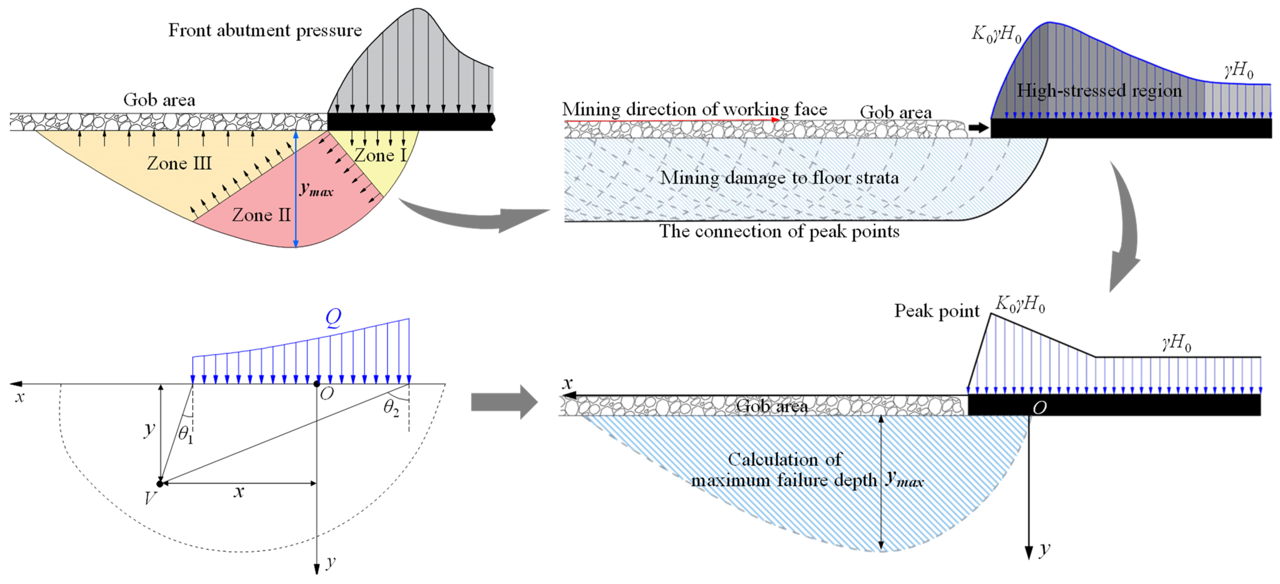
2.1. Study on Floor Damage due to Mining of Overlying Coal Seam

In the mining process of the working face, the abutment pressure in front of the coal wall will lead to the destruction of the floor. As shown in Figure 1, according to the plastic theory, the limit equilibrium zone generated by the front abutment pressure on the floor can be divided into three regions: active stress zone (zone I), transition zone (zone II), and passive stress zone (zone III) [37]. However, the mining of the working face is a continuous process. With the constant advancement of the working face, the front abutment pressure is constantly moved forward in the limit equilibrium zone. By connecting the peak point of its maximum depth ymax, the damage zone in the floor generated by working mining can be obtained.
As shown in Figure 1, the original rock stress is γH0, γ is the average unit weight, kN/m3. H0 is the buried depth of coal seam, m. The peak value of the front abutment pressure of the working face is set as K0γH0; this linear load Q is simplified into a uniform load for calculation which is sufficient to meet the accuracy requirements of the project [38], as shown in Equation (1).
Q = ( K 0 + 1 ) γ H 0 2
where K0 is the maximum stress concentration factor. According to the stress solution of a half-plane body under uniformly distributed normal load on the boundary in elasticity, the three stress components of any point V can be obtained:
{ σ x = Q 2 π [ 2 ( θ 2 θ 1 ) ( sin 2 θ 2 sin 2 θ 1 ) ] σ y = Q 2 π [ 2 ( θ 2 θ 1 ) + ( sin 2 θ 2 sin 2 θ 1 ) ] τ x y = τ y x = Q 2 π ( cos 2 θ 1 cos 2 θ 2 )
where θ1 and θ2 are the two included angles between point V and stress section, respectively. According to the elasticity, the principal stress at any point in the bottom plate is:
σ 1 σ 3 } = σ x + σ y 2 ± ( σ x σ y 2 ) 2 + τ x y 2
where σ1 and σ2 are the maximum and minimum principal stress of the rock mass of the floor, MPa. From Equations (2) and (3), the principal stress at any point of the floor caused by mining is shown below [37].
{ σ 1 = Q π [ ( θ 1 θ 2 ) + sin ( θ 1 θ 2 ) ] γ y σ 3 = Q π [ ( θ 1 θ 2 ) sin ( θ 1 θ 2 ) ] γ y
Mohr–Coulomb yield criterion in geotechnical engineering is:
1 2 ( σ 1 σ 3 ) = c 0 cos φ 0 + 1 2 ( σ 1 + σ 3 ) sin φ 0
where c0 is the average cohesion of floor rock mass, MPa, φ0 is the average internal friction angle of floor rock mass, °. The mining damage depth y of the floor can be obtained from Equations (4) and (5):
y = Q 1000 π γ ( θ sin θ sin φ 0 ) + c 0 cos φ 0 1000 γ sin φ 0
where θ = θ1 + θ2. From Equation (6), θ = arccos (sin φ0). Therefore, the maximum depth ymax is:
y max = Q 1000 π γ ( arccos ( sin φ 0 ) sin [ arccos ( sin φ 0 ) ] sin φ 0 ) + c 0 cos φ 0 1000 γ sin φ 0
From Equation (7), the relationship between the depth of floor damage caused by mining and the depth of burial, the stress concentration factor, the internal friction angle, and cohesion can be obtained as shown in Figure 2.
It can be seen from Figure 2a that the maximum damage depth of the bottom plate increases by 7.5 times when the buried depth is increased by eight times. This depth increases by 2.4 m for every 100 m increase in buried depth. As shown in Figure 2b, the maximum damage depth decreases with the rise of the cohesion and internal friction angle. The cohesion and internal friction angle increase two times, and the depth decreases by 0.62 times. It can be seen from Figure 2c that the higher the stress concentration coefficient, the greater the maximum damage depth gradually. The stress concentration factor increases two times, and the depth increases 1.53 times.
The above is a calculation method to obtain the damage depth of the bottom plate. If it can be measured in the field (such as seismic wave velocity tomography, AE, micro-seismic monitoring, etc.) [39,40,41,42], the actual measurement data can be used; if the upper coal seam has already been mined and the field data cannot be obtained, you can refer to the calculation method in this paper.

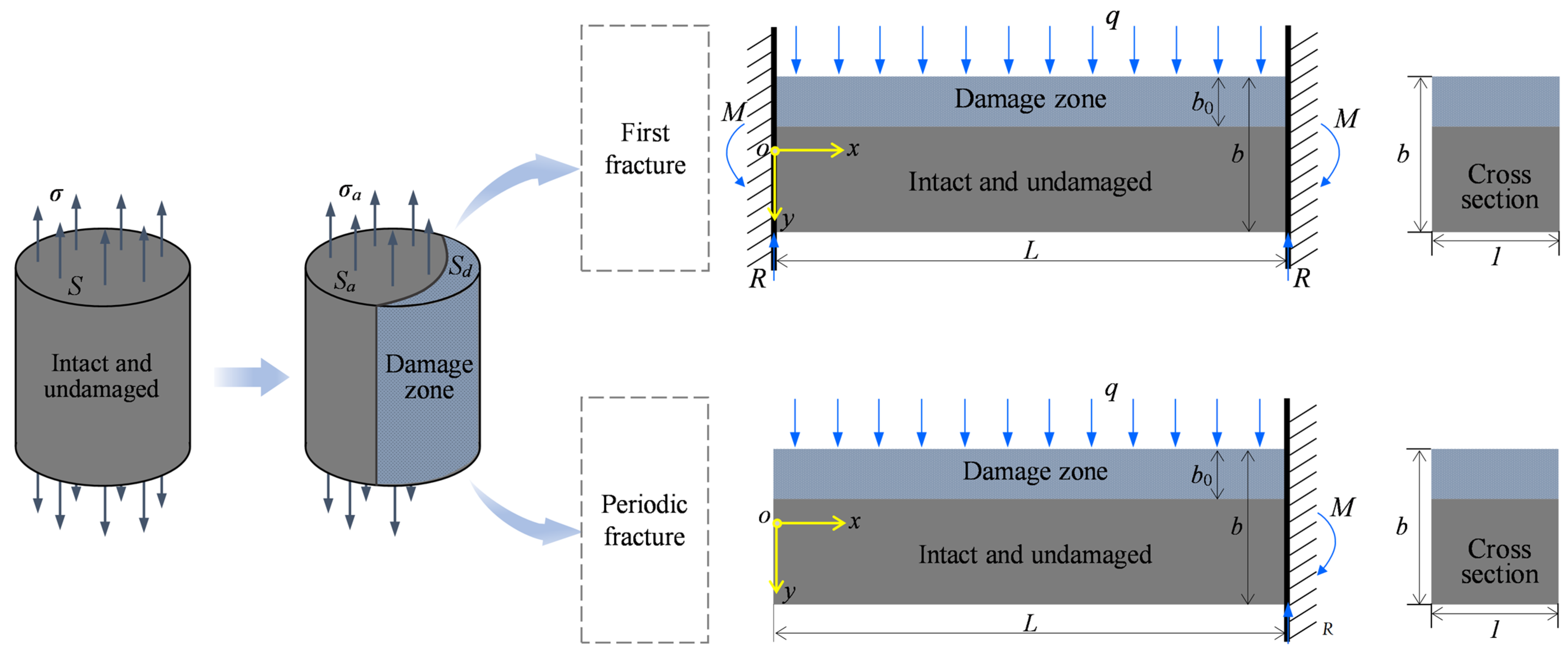
2.2. Types of the Damaged Main Roof in the Lower Coal Seam

The mining of the upper coal seam causes damage to the floor of the gob area, and the floor is the roof of the lower coal seam. As shown in Figure 3, the main roof is divided into four categories according to the degree of damage to the main roof of the lower coal seam. Figure 3a represents complete damage to the base roof. In Figure 3b, the main roof damage area accounts for more than 50% in the vertical direction and belongs to extensive damage. In Figure 3c, the percentage of main roof damage area in the vertical direction is ≤50%, which belongs to local damage. Figure 3d shows no damage to the main roof.
In this paper, the linkage between the upper broken main roof and the lower damaged main roof is mechanically analyzed and studied.

3. Stability Calculation and Analysis of Damaged Main Roof in Underlying Coal Seam

According to the basic principle of damage mechanics, the damaged main roof’s mechanical properties and instability conditions are studied.

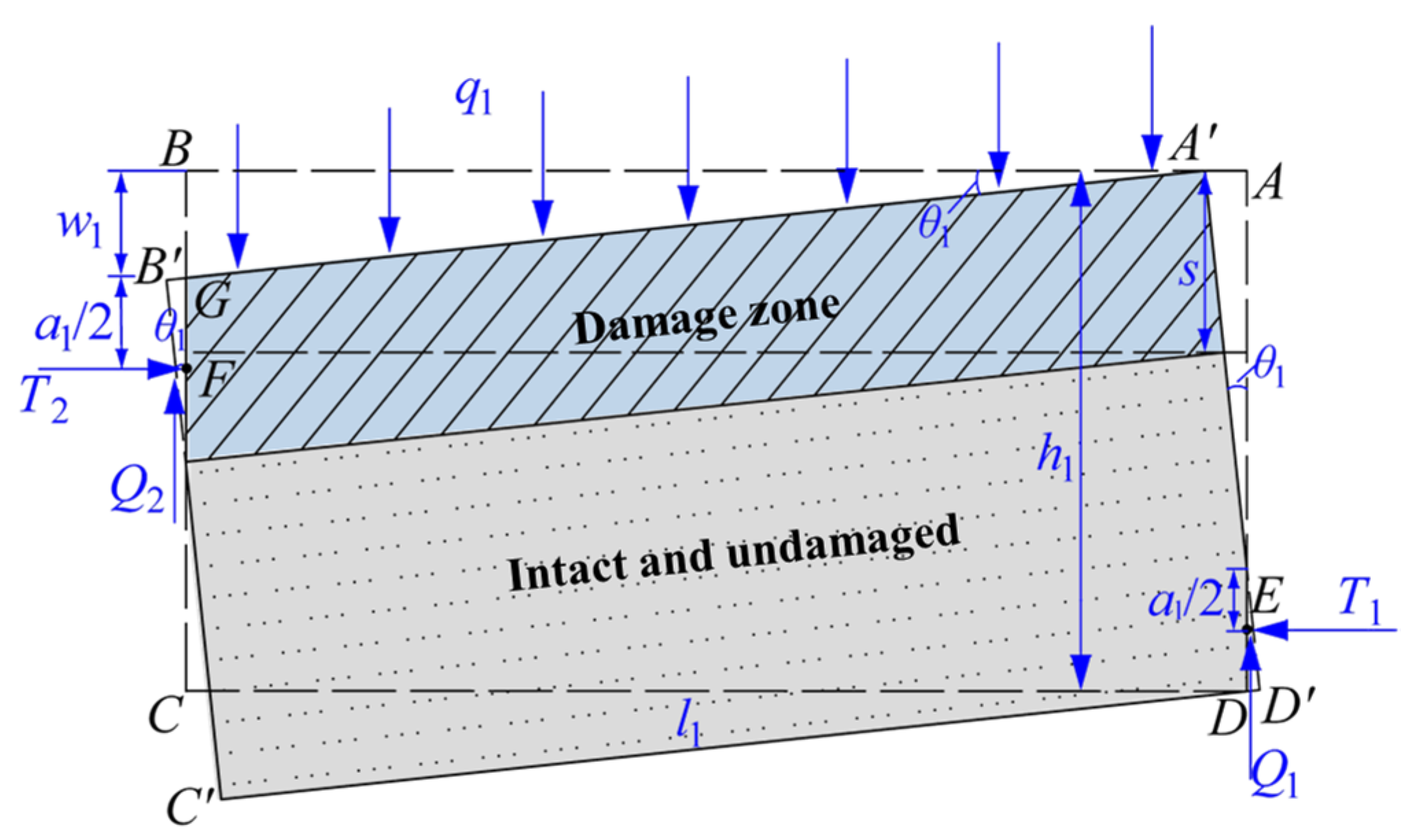
3.1. Analysis of First and Periodic Fracture of the Damaged Main Roof

As shown in Figure 4, for continuous materials, the uniaxial tensile specimen is subjected to tensile force P, the intact non-damaged micro section is subjected to uniformly distributed load, and its area is S. The actual stress area of the damaged rock block is Sa, the cross-sectional area of the lesion zone is Sd. According to the damage theory, the damage variable D is shown in Equation (8) below [34].
{ σ a = P S a , σ d = 0 S a + S d = S D = S d S
(1)
Clamped beam model for the first fracture of the damaged main roof
In general, the first fracture of the main roof is simplified as a two-dimensional clamped beam model [12]. As shown in Figure 4, the length of the beam is L, the height of the beam is b, the width is 1, the height of the damage band is b0, the upper surface of the beam is subjected to a uniformly distributed load q, the exact solution of the horizontal stress is obtained [43]:
σ x = 6 b 3 q x ( x L ) y + 1 b 3 q ( 4 y 2 L 2 ) y + 3 ( 2 v 1 ) 5 b q y 1 2 v q
where ν is Poisson’s ratio. The maximum bending moment occurs at both ends of the beam, where the maximum tensile stress first exceeds the tensile strength limit of the material [σt] [34]. For the damaged main roof beam model, its tensile strength limit is:
σ 1 D [ σ t ]
Then (0, −b/2) is substituted into Equation (9) to obtain the limit span Lf of the damaged main roof beam during the first fracture. The lumpiness if of the fractured rock block (lumpiness is also called fracture degree [12], which refers to the height-length ratio of rock block, that is, i = b/L):
{ L f = b 2 [ σ t ] ( 1 D ) q + 2 + 11 ν 5 i f = 1 2 [ σ t ] ( 1 D ) q + 2 + 11 ν 5
(2)
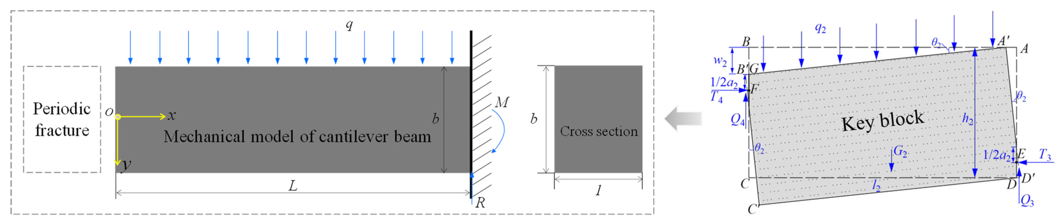
Cantilever beam model for periodic fracture of the damaged main roof
The periodic weighting interval of the damaged main roof is usually determined according to the cantilever beam [12]. As shown in Figure 4, the exact solution for the horizontal stress of the damaged cantilever beam is obtained with the same mechanical parameters [43]:
σ x = 6 b 3 q x 2 y + 4 b 3 q y 3 3 5 b q y
Substituting (L, −b/2) into Equation (12), and the limit span Lp of periodic fracture of the damaged main roof beam and the lumpiness ip are as follows:
{ L p = 3 b 3 [ σ t ] ( 1 D ) q + 1 5 i p = 3 [ σ t ] ( 1 D ) q + 1 5
(3)
The first and periodic weighting intervals of the damaged main roof
As shown in Figure 5, with the increase in damage equivalent D, the main roof’s first and periodic fracture intervals decrease, and the decreasing rate increases gradually. At the same time, when the load q of the damaged main roof is small, the damage degree of the ultimate span with a fracture is more obvious. When q is small, with the increase in damage degree, the first fracture interval of the main roof can be reduced by 61.3%, while the periodic fracture interval can be reduced by 78.7%.

3.2. Stress Analysis of Key Block of the Damaged Main Roof

As shown in Figure 6, the damage degree will affect the contact length and rotation angle of the key block, and the stress analysis of the damaged main key block is carried out.
For the damaged key blocks, the contact length between the two ends is a1 [12]:
a 1 = 1 2 ( h 1 l 1 sin θ 1 )
where l1 and h1 are the length and height of key blocks. According to the stress analysis, the equilibrium relations between ∑FX = 0 and ∑FY = 0 are listed:
{ T 1 = T 2 q 1 w 1 csc θ 1 = Q 1 + Q 2
where T1 and T2 are horizontal thrust or extrusion forces between rock blocks, q1 is the overlying load of the rock block, Q1 and Q2 are shear forces at the contact of rock blocks.
According to the “voussoir beam” theory, there is only horizontal compressive force at the hinge area F [12], Q2 = 0. w1 is the vertical subsidence of point B during rotation, and its formula is:
w 1 = l 1 sin θ 1
Take the moment balance ∑ME = 0 for the action point E of horizontal extrusion pressure:
q 1 w 1 csc θ 1 [ 1 2 w 1 cot θ 1 + ( h 1 a 1 ) tan θ 1 ] = T 2 ( h 1 w 1 1 2 a 1 1 2 a 1 )
The expression of horizontal thrust T can be obtained from Equation (17):
T = q 1 l 1 [ l 1 cos θ 1 + ( h 1 + l 1 sin θ 1 ) tan θ 1 ] h 1 l 1 sin θ 1
The expression of Equation (18), which is transformed into containing i is:
T = q 1 L [ cos θ 1 + ( i + sin θ 1 ) tan θ 1 ] i sin θ 1
Substituting Lf, Lp, if, and ip can show that the horizontal thrust at the first and periodic fracture of the damaged main roof is affected by the damage equivalent D, as shown in Figure 7.
As shown in Figure 7, the horizontal thrust between key blocks decreases with the increase in damage equivalent when the damaged main roof is broken for the first and periodic fracture. The difference is that when the rotation angle is large, the decreasing trend of the horizontal thrust of the first fracture is fast at first and then slow, and the larger the rotation angle, the greater the decreasing degree (84%→91%), while the horizontal thrust of the periodic fracture has no apparent decreasing trend. The decreasing degree is mainly unchanged (94%) with the larger rotation angle.

3.3. Conditional Formula of Main Roof Instability

The sliding and rotary instability conditions of the damaged main roof during the first and periodic fracture are derived [44].
(1)
Sliding instability of the damaged key block
The maximum shear stress of the damaged key block occurs at point E. To prevent the structure from slipping instability at point E [12], it should meet the following requirements:
T tan φ Q 1
where tan φ is the friction coefficient between rocks, Q1 is the shear force at point E, which can be obtained from Equation (15):
Q 1 = q 1 w 1 csc θ 1
The critical lumpiness ism of sliding instability is obtained respectively when the damaged key block is broken:
i s m = sin θ 1 + ( sin θ 1 tan θ 1 + cos θ 1 ) tan φ 1 tan θ 1 tan φ
As shown in Figure 8, the critical lumpiness ism of sliding instability increases with the increase in the rotary angle of the key block, and the larger the tan φ, the larger the growth rate and the faster the growth rate, and the smaller the tan φ, the constant growth rate of the critical lumpiness ism. Therefore, the smaller the friction coefficient is, the lower the critical lumpiness of the main roof sliding instability is, and the smaller the influence of the rotary angle is.
ism is substituted into Equations (11) and (13), respectively, and the relations between critical loads qfsm, qpsm and D (damage variable) in two states are obtained:
{ q f s m = 10 i s m 2 [ σ t ] ( 1 D ) 5 i s m 2 ( 2 + 11 ν ) q p s m = 5 i s m 2 [ σ t ] ( 1 D ) 15 i s m 2
As shown in Figure 9, the critical load of key block sliding instability when the main roof is broken for the first time is more significant than that of periodic fracture. Under the same rotation angle, the critical load of the first fracture is about 8.3 times that of the periodic fracture. In addition, the critical loads of both of them decrease with the increase in damage degree, and the reduction degree exceeds 80%.
(2)
Rotation instability of the damaged key block
Excessive horizontal compressive force T between rock blocks leads to the crushing of rock blocks at the corner and the instability of the whole key block [12], and the conditional expression for the instability of rotation is:
T a 1 η [ σ c ] D
where η is the coefficient; [σc]D is the compressive strength of damaged rock mass, and its value should be:
[ σ c ] D = [ σ c ] ( 1 D )
where [σc] is the compressive strength of intact rock mass. Therefore, the critical load qrm of the damaged key block for rotary instability is:
q r m = η [ σ c ] ( 1 D ) ( i sin θ 1 ) 2 2 [ cos θ 1 + ( i + sin θ 1 ) tan θ 1 ]
As shown in Figure 10, the critical load of the damaged key block for rotary instability decreases with the increase in damage equivalent, and the larger the rotary angle of the key block, the smaller the critical load of rotary instability; while the larger the lumpiness of the key block, the larger the critical load of rotary instability. Therefore, no matter what kind of instability forms, the damage degree dramatically reduces the stability of key blocks.

4. Calculation and Analysis of the Interaction Mechanism of the Upper and Lower Main Roofs

In the close coal seam group, when the underlying coal seam is mined under the gob area of the overlying coal seam, it is necessary to consider the interaction between the overlying broken main roof and the damaged main roof of the underlying coal seam.

4.1. Main Roof Mechanics Analysis of the Upper Coal Seam

The periodic fracture only needs to be considered to analyze the main roof of the overlying coal seam because the first limit span is minimal compared with the whole propulsion distance.
(1)
Periodic fracture interval of the main roof of the overlying coal seam
As shown in Figure 11, cantilever beam model with periodic fracture of the main roof, the limit span of periodic fracture of main roof beam in overlying coal seam Lup and the lumpiness of fractured rock blocks iup are as follows:
{ L u p = 3 b 3 [ σ t ] q + 1 5 i u p = 3 [ σ t ] q + 1 5
(2)
Sliding instability of the key block of the overlying coal seam
For sliding instability, similarly, the horizontal thrust Tup between key blocks can be obtained when the main roof of the overlying coal seam is broken.
T u p = q 2 l 2 [ l 2 cos θ 2 + ( h 2 + l 2 sin θ 2 ) tan θ 2 ] h 2 l 2 sin θ 2
where q2 is load borne by the key block of the overlying coal seam, l2 and h2 are respectively length and height of the key block, θ2 is the rotary angle of the key block. Thus, the critical lumpiness iupm of rock mass sliding instability when the key block in the main roof is broken can be obtained. The critical load qusm of sliding instability can be obtained by substituting iupm into Equation (28). The expressions of the two are:
{ i u p m = cos θ 2 tan φ + sin θ 2 ( 1 + tan θ 2 tan φ ) 1 tan θ 2 tan φ q u s m = 5 i u p m 2 [ σ t ] 15 i u p m 2
(3)
Rotary instability of the key block of the overlying coal seam
For rotary instability, similarly, the critical load qurm of rotary instability when the key block of overlying coal seam is broken periodically can be calculated:
q u r m = η [ σ c ] ( i u p sin θ 2 ) 2 2 [ cos θ 2 + ( i u p + sin θ 2 ) tan θ 2 ]

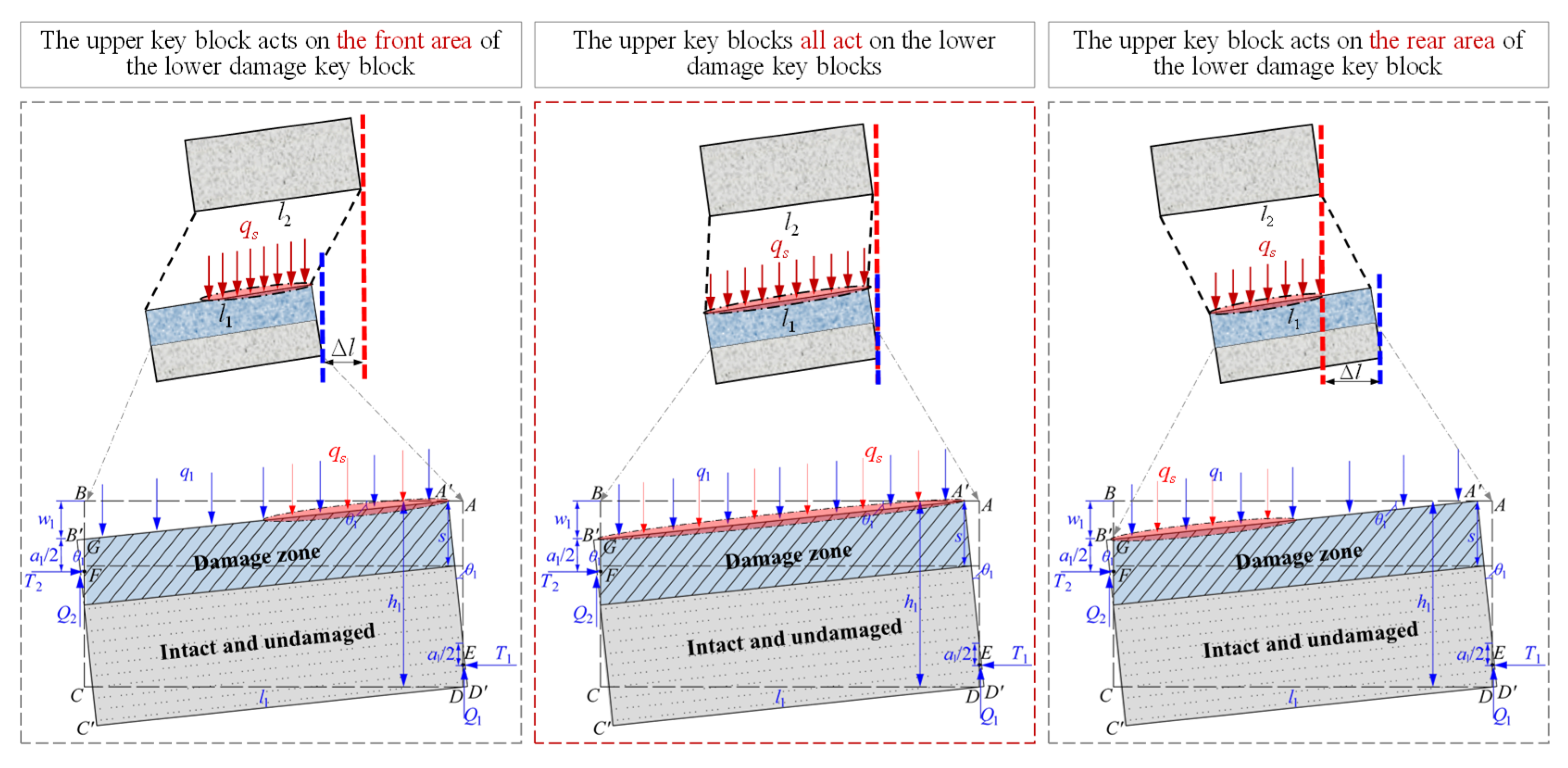
4.2. Interaction between Key Blocks in the Main Roof of Overlying and Underlying Coal Seams

As shown in Figure 12, as the overlying coal seam has been mined, its main roof has been broken, and the gob area has been compacted. When the underlying coal seam is mined below its gob area, the key block of its broken main roof moves for the second time with the movement of the overburden of the lower coal seam. According to the movement relationship between them, five interaction forms are summarized (what is studied here is the key blocks that are moving, not the blocks that have collapsed and stabilized):
(1)
The fracture line of the main roof in the overlying coal seam is significantly advanced. The rotation of the key block only acts on the local area in front of the damaged key block of the lower layer, while most of the key block acts on the main roof that has not moved, and the two key blocks that have moved only act locally.
(2)
The fracture line of the main roof in the overlying coal seam is slightly ahead. The rotation of its key block acts on most of the damaged key block of the lower coal seam, while the other small parts act on the damaged main roof without movement, and the interaction area of the two moving key blocks is large.
(3)
The fracture lines of the main roof in the overlying and underlying coal seams overlap. The rotation of the key block of the upper coal seam all acts on the damaged key block of the lower coal seam, and the interaction degree of the two moving key blocks is the strongest.
(4)
The fracture line of the main roof in the overlying coal seam lags slightly, and the key block rotates in most areas of the key block moving in the lower layer, while the other small parts act on the key block broken in the lower layer. The interaction area of the two moving key blocks is also large.
(5)
The fracture line of the main roof of the upper coal seam lags by a large margin. The rotation of its key block only acts on the local area behind the key block that has moved in the lower layer, while most of it acts on the damaged key block in the lower layer, and the two key blocks that have also moved only act locally.

4.3. Interaction Mechanical Model of the Upper and Lower Key Blocks with Different Properties

As shown in Figure 13, summarizing the above five interaction relationships, three overlying and underlying key blocks interaction models are obtained: (1) The rotation of the overlying key block acts on the front area of the underlying damaged key block; (2) The rotation of the overlying key block acts on the underlying damaged key block; (3) The rotation of the overlying key block acts on the rear area of the underlying damaged key block.
The key block of the upper coal seam moves because it is unable to bear the load of its load layer, then its structure becomes unstable and turns around; the load value qs transmitted downward by the key block is a specific value, the most fundamental is whether this load acts on the key block in the underlying main roof or other areas. From this analysis, it can be seen that when the fracture lines of the overlying and underlying main roof overlap, the load transmitted by the upper key block acts on the key block in the underlying main roof, which is the worst case of instability.
Therefore, this paper mainly studies the stability of the two key blocks in the case of deterioration; that is, the lower damaged key block bears the effect of q + qs, first fracture interval Lsf, periodic fracture interval Lsp, and lumpiness isf, isp:
{ L s f = b 2 [ σ t ] ( 1 D ) q + q s + 2 + 11 ν 5 , i s f = 1 2 [ σ t ] ( 1 D ) q + q s + 2 + 11 ν 5 L s p = 3 b 3 [ σ t ] ( 1 D ) q + q s + 1 5 , i s p = 3 [ σ t ] ( 1 D ) q + q s + 1 5
For the sliding instability, similarly, the horizontal thrust Tst of the damaged key block under the additional load of the key block in the overlying coal seam is obtained:
T s t = ( q 1 + q s ) l 1 [ l 1 cos θ 1 + ( h 1 + l 1 sin θ 1 ) tan θ 1 ] h 1 l 1 sin θ 1
From Equation (22), when the key block in the main roof is broken, the critical lumpiness is independent of the load value; thus, istm = ism. And substitute istm into Equation (22) to obtain the relationship between critical load qsfs, qsps and damage variable D of key block sliding instability when the underlying damaged main roof is broken for the first time and periodically:
{ q s f s = 10 i s t m 2 [ σ t ] ( 1 D ) 5 i s t m 2 ( 2 + 11 ν ) q s p s = 5 i s t m 2 [ σ t ] ( 1 D ) 15 i s t m 2
For rotary instability, the critical load qsrm of rotation instability of the damaged key block under the additional load of key block in the upper coal seam can be calculated:
q s r m = η [ σ c ] ( 1 D ) ( i sin θ 1 ) 2 2 [ cos θ 1 + ( i + sin θ 1 ) tan θ 1 ] q s
Thus, the catastrophe condition formula for the instability of the damaged key block when the overlying broken main roof and the underlying damaged main roof overlap the fracture line is derived, the stability and the additional load transmitted of the key block in the overlying main roof are considered, the following examples will describe the application of this conditioning formula.

5. Analysis of Field Application Results

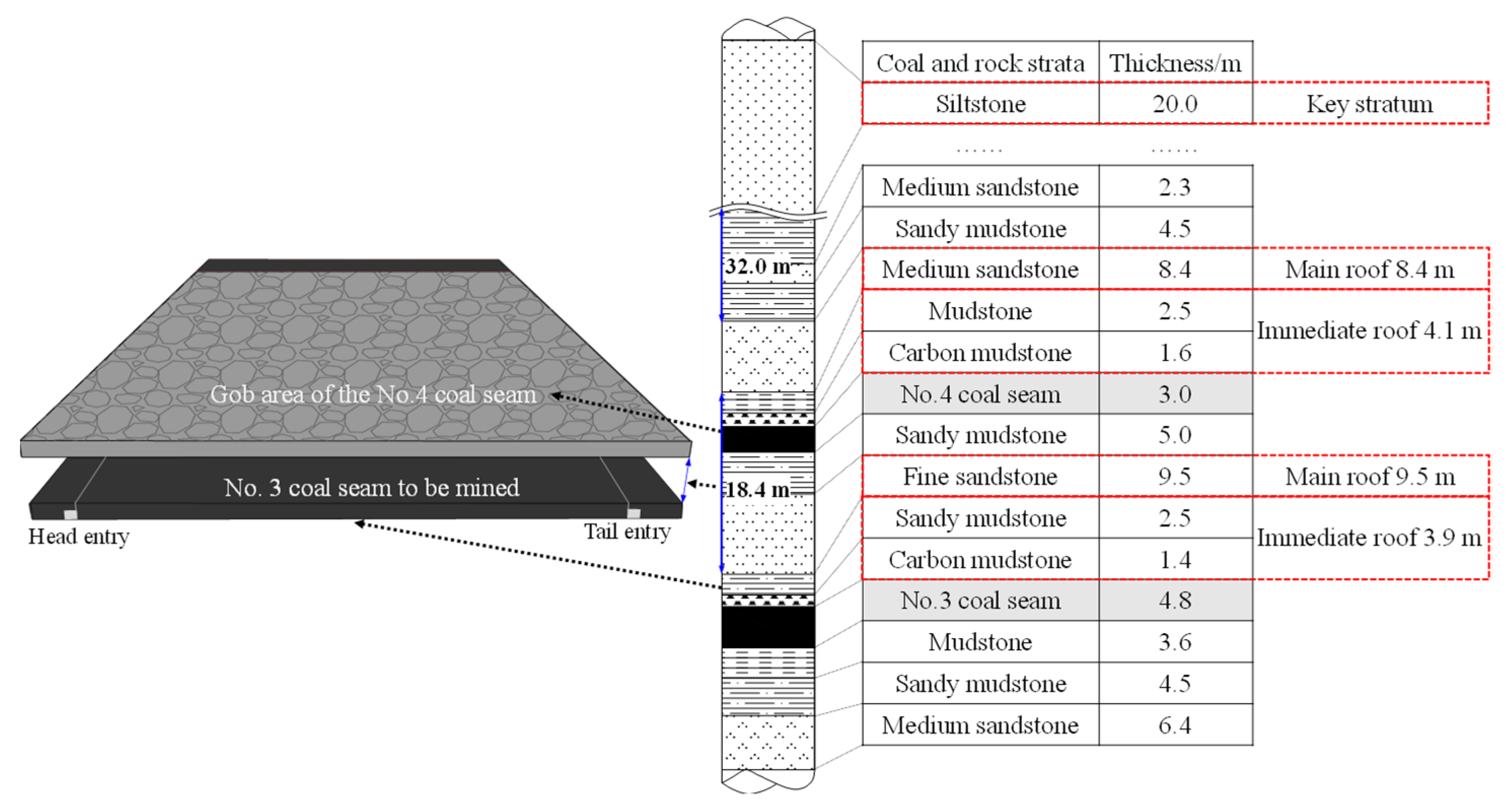
5.1. Geological Survey of Engineering Application Examples

As shown in Figure 14, the No. 4 coal seam of Swallow Mountain mine is firstly mined, and its main roof has collapsed and compacted the gob area, while the underlying No. 3 coal seam is the coal seam being mined, and the vertical distance between the two coal seams is 18.4 m, which belongs to the close-distance coal seams. The formulas in this paper are all applied to study the interaction between two main roofs in close-distance coal seams, so the theory is used to analyze the fracture step and block stability of the main roofs in the case of coal seam mining.
The buried depth of the underlying coal seam is about 400 m, the main roof thickness is 9.5 m, and its distance from the overlying coal seam is 5.0 m. According to Equation (7), it can be seen that the damage depth of the floor caused by the mining of the overlying coal seam is 8.77 m, so the damage depth of the main roof of the underlying coal seam is 3.77 m, and the intact undamaged depth is 5.73 m. Therefore, the damage equivalent D of the main roof is 0.397, which belongs to the local damage type.
The calculation shows that the main roof of the overlying coal seam bears the load of 0.864 MPa, the limit span of periodic weighting Lup is 14 m, the broken expansion coefficient is 1.4 [12], and the maximum rotary angle is 5.7°. The damaged main roof of the underlying coal seam bears a load of 0.502 MPa. The ultimate span of the first weighting Lf is 40 m, which is 22% lower than that of 51 m without damage, and the maximum rotary angle is 4.6°; The ultimate span Lp of periodic weighting is 16 m, which is 24% lower than that of 21 m without damage, and the maximum rotary angle is 11.6°.

5.2. Stability Calculation of the Upper and Lower Main Roofs with Different Properties

(1)
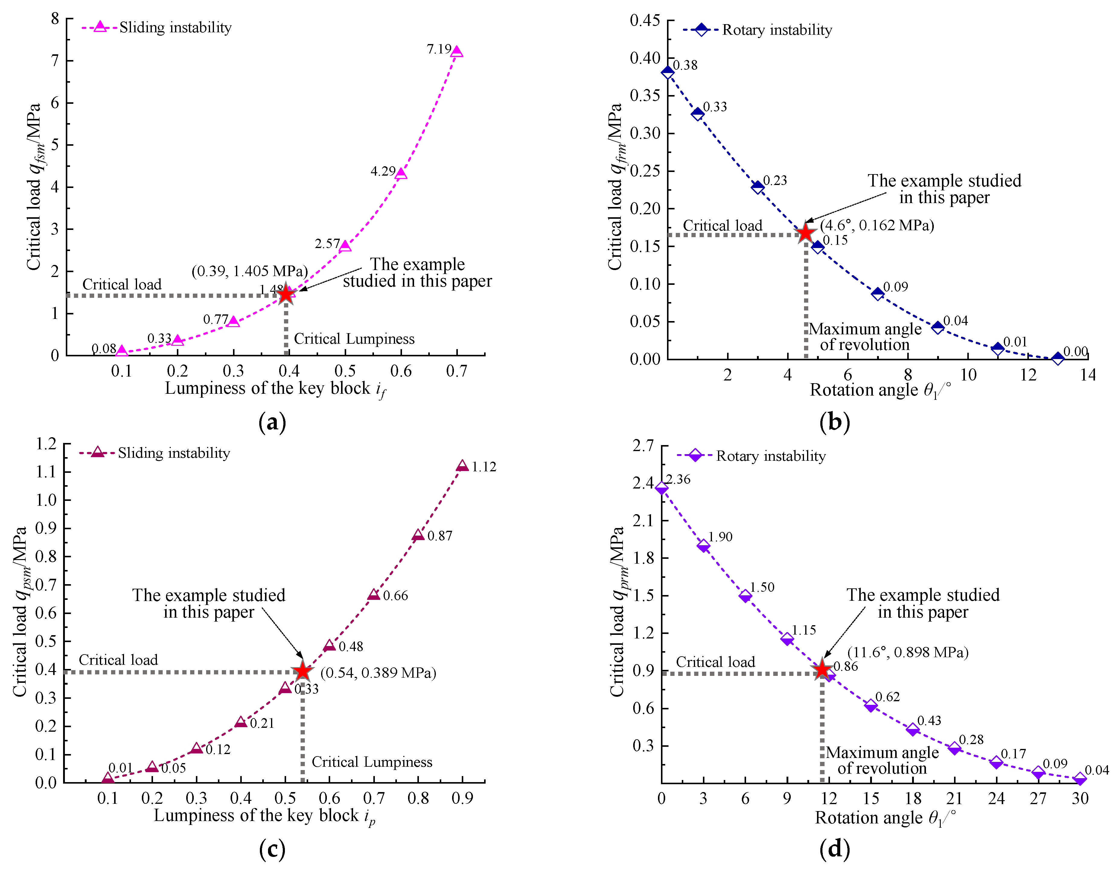
Instability analysis of the main roof of the overlying coal seam
When mining the working face of the underlying coal seam, it is necessary to analyze the linkage effect of the key blocks in the main roof of the two coal seams. To maintain stability, the key block in the overlying coal seam will transfer the load to the damaged key block in the underlying coal seam. For the damaged key block, this load is an additional load. Therefore, firstly, the stability of the key block in the main roof of the underlying coal seam is analyzed.
As shown in Figure 15a, for the sliding instability, the critical lumpiness of the key block can be calculated as 0.41. Its bearing capacity is 0.375 MPa, which is insufficient to bear the overburdened load. The sliding instability will occur, and the load value of 0.489 MPa will be transmitted downward. As shown in Figure 15b, for rotation instability, it has a bearing capacity of 2.889 MPa at the maximum angle of 5.7°, so rotation instability will not occur.
(2)
Instability analysis of the damaged main roof of the underlying coal seam
① The first fracture of the damaged main roof
As shown in Figure 16a, when the damaged main roof is first fracture, for sliding instability, its critical lumpiness is 0.39, corresponding to the bearing capacity of 1.405 MPa, so the damaged key block will not occur sliding instability. As shown in Figure 16b, for rotary instability, when the maximum rotary angle is 4.6°, it has only a bearing capacity of 0.162 MPa, so the damaged key block will have rotary instability.
② The periodic fracture of the damaged main roof
When the damaged main roof is fractured periodically, similarly, as shown in Figure 16c, for the sliding instability, its critical lumpiness is 0.54, and its bearing capacity is 0.389 MPa, so the sliding instability of the damaged key block will occur. As shown in Figure 16d, for rotary instability, when the maximum angle is 11.6°, it corresponds to the bearing capacity of 0.898 MPa, so rotary instability will not occur.
(3)
Combined stability analysis of the upper and lower main roofs with different properties
According to the stability of the overlying and underlying main roofs, the critical load curve is divided into three regions. Region I: joint instability region, and the upper and lower key blocks are all unstable; Region II: stability judgment region, the lower damaged key block remains stable under its own load (the load of the rock layer between the two main roofs), but it bears the additional load, and its stability needs to be judged; Region III: combined stability region, the upper and lower key blocks interact with each other and remain stable.
① The first fracture of the damaged main roof under the additional load
The upper main roof cannot keep itself stable and will transmit additional load downward, so the damaged key block that is the first fracture will bear the additional load. As shown in Figure 17a, there are three regions in the critical load curve of sliding instability. When combined with this calculation example, the stability state of region II is judged. From the above, the value of the additional load is 0.489 MPa, and the bearing capacity of the damaged key block that is the first fracture is 0.903 MPa. Therefore, the sliding instability of the damaged key block will not occur under the action of the additional load. However, as shown in Figure 17b, the critical load curve of rotary instability only exists in region I. That is, the two key blocks cannot maintain their own balance, and the support needs to provide 0.829 MPa to ensure the balance.
The support bears a load of top coal mass and immediate roof (0.159 MPa) and inhibits the rotary instability of the damaged main roof, with a total load of 0.988 MPa. ZF12000/23/35 top coal caving support is adopted on-site, with the roof-control distance of 5.18 m and the bearing capacity of the support reaching 1.3 MPa. Therefore, during the initial pressure, the support function of the support can keep the overlying and underlying main roofs with different properties.
② The periodic fracture of the damaged main roof under the additional load
Similarly, for the damaged key block that bears additional load and breaks periodically, as shown in Figure 17, there are three regions in the critical load curve of sliding and rotary instability. For the discrimination of region II, as shown in Figure 17c, it is known that the instability of the overlying key block transmits a critical load of 0.489 MPa, and the damaged key block cannot maintain its own stability and instability. Therefore, the support of the working face needs to bear a total load of 0.761 MPa to maintain the stability of the two key blocks; As shown in Figure 17d, it is known that the load is 0.898 MPa of the damaged main roof to inhibit the rotary instability during periodic fracture, and there is 0.396 MPa after bearing its own load layer. Therefore, the rotary instability will occur under the action of additional load, but the support of the support is sufficient to maintain its stability.
In this calculation example, the two main roof key blocks move jointly; the lower damaged key block is prone to rotation instability with the first fracture of the main roof and sliding instability when the main roof is broken periodically. Still, it can remain stable under the support of the working face support, which also verifies the rationality of the support selection.

5.3. Observation of Working Face Support Resistance

Observe the time-weighted mean resistance of the support in the 3215 working face when mining the lower coal seam, as shown in Figure 18.
As shown in Figure 18a, the first pressure interval of the support near the end of the 3215 working face is 41.5 m, and the average periodic weighting interval of the first nine times is 16.5 m. As shown in Figure 18b, the first pressure interval of the support in the middle of the working face is 38.3 m, and the average periodic weighting interval of the first nine times is 15.8 m. The results are close to the theoretical calculation. At the same time, the variation range of ground pressure strength and pressure in the middle of the working face is more significant than that in the end area, and the supports are in good working condition. When the working face is weighted for the first time, the support bears the maximum pressure and is close to the ultimate bearing capacity; When the working face is weighted periodically, the support pressure is significant, but they are all within the controllable range, which shows that the support selection is reasonable and verifies the above calculation results.

6. Conclusions

(1)
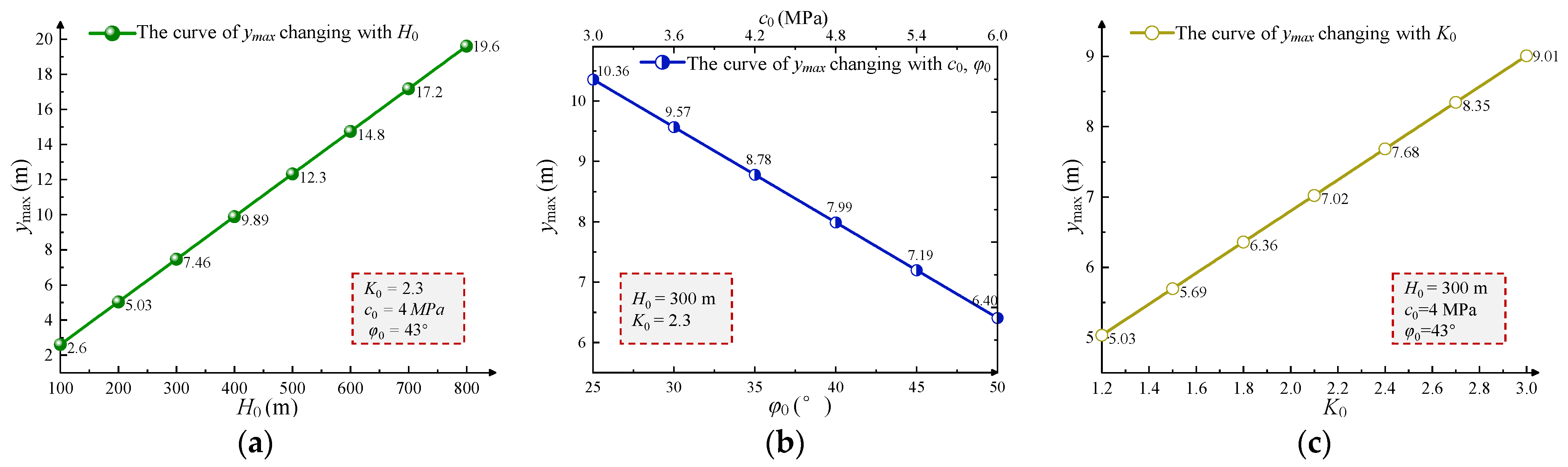
The mining of the upper coal seam in the group of close-distance coal seams will trigger damage to the floor. The formula for calculating the damage depth of the floor is proposed, and the damage depth increases by 2.4 m for every 100 m increase in burial depth; the cohesion and internal friction angle increase to double, and the damage depth decreases to 0.62 times; the stress concentration coefficient increases to double and the damage depth increases to 1.53 times.
(2)
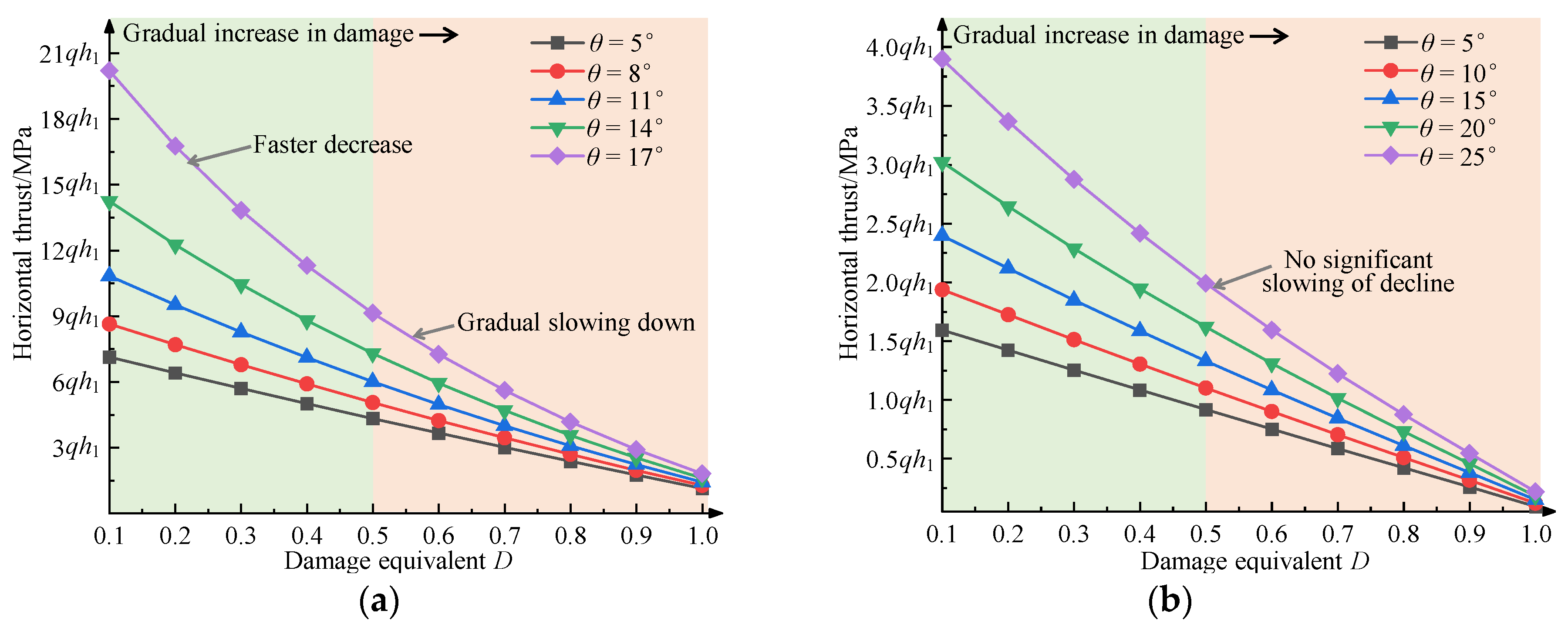
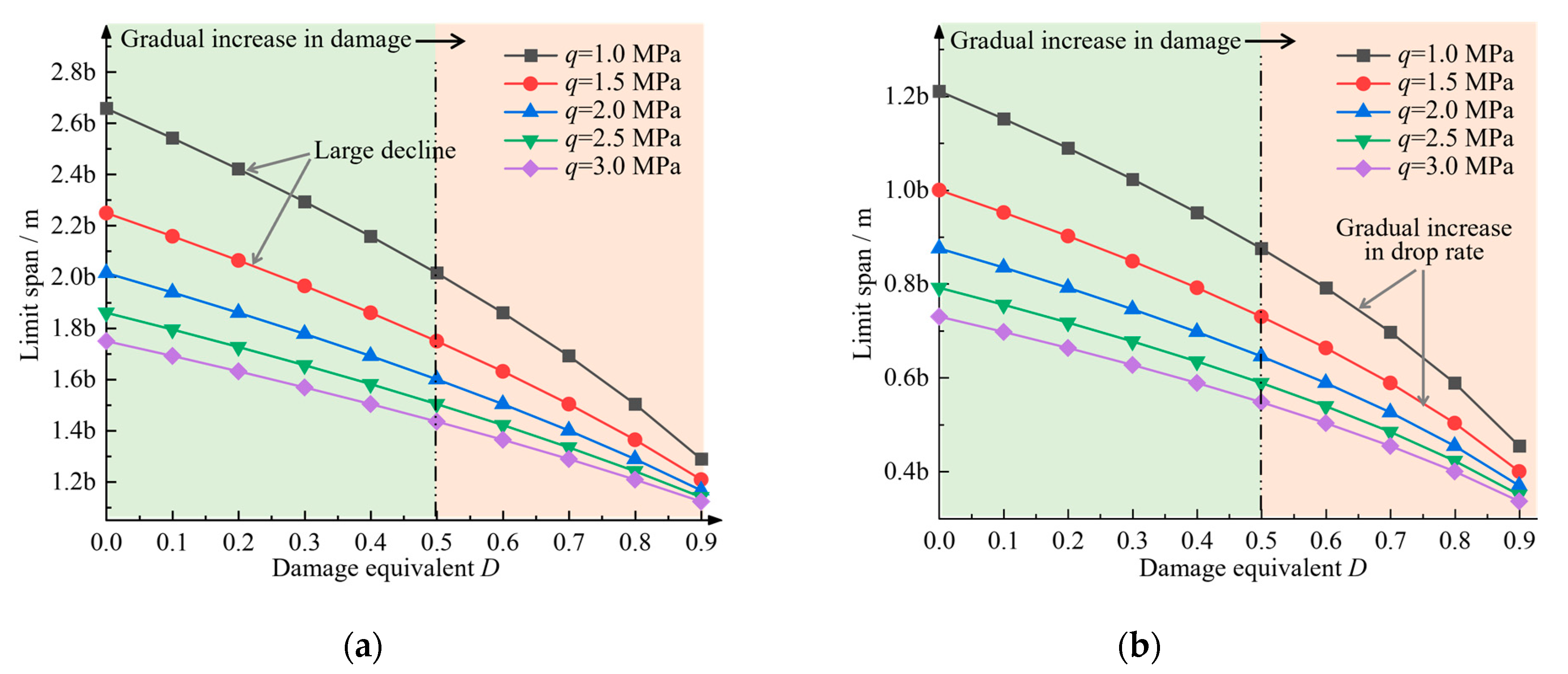
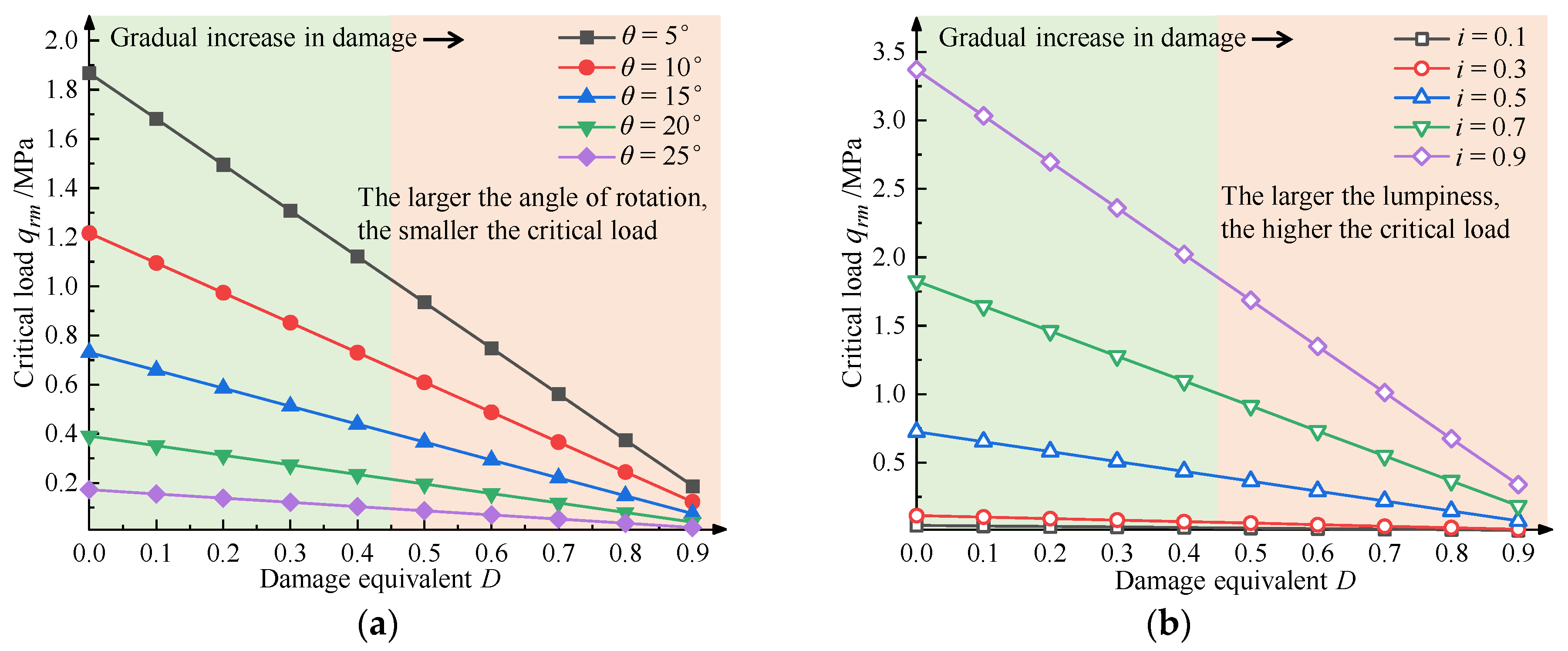
Four types of the damaged main roof of the lower coal seam are proposed, and the mechanical models of the first and periodic fractures of the damaged main roof are established. The limited span of the main roof during the first and periodic fractures, the horizontal thrust of the key block, and the critical load of instability are significantly reduced by the damage; however, there are differences in reducing regularity under different loads rotary angles, and lumpiness.
(3)
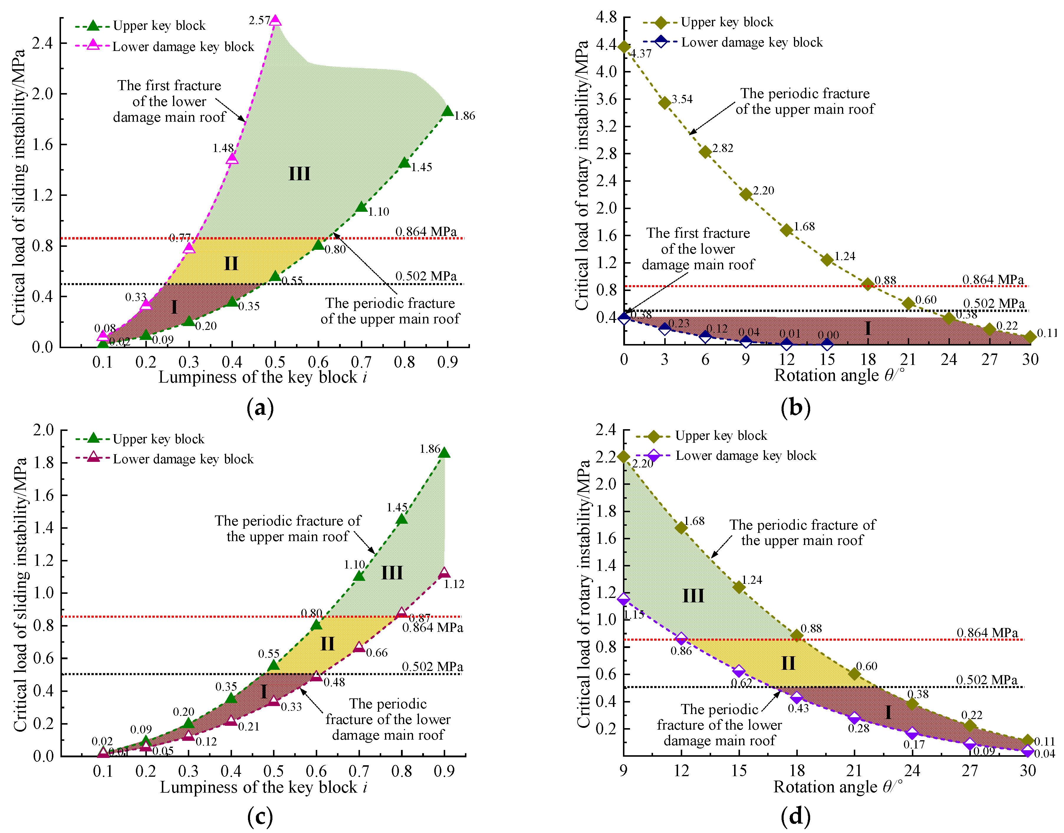
The mechanical model of the interaction mechanism and stability of the upper and lower main roofs with different properties is established. When the fracture lines of the upper and lower main roofs overlap, the stability of the damaged key blocks is the lowest. There are three linkage stability regions in the critical load curves of the two key blocks: joint stability region, stability judgment region, and combined stability region.
(4)
In the example of this paper, the damage equivalent D is 0.397 of the damaged main roof, belonging to the local damage type. The first and periodic pressure interval is 40 m and 16 m, decreasing by 22% and 24%, respectively, compared with the no damage.
(5)
A supporting load of 0.489 MPa is required to maintain the stability of the upper key block, and the lower damaged key block is prone to rotary and sliding instability during the first and periodic weighting, respectively. Thus, the supports need to bear a total of 0.988 MPa and 0.761 MPa to maintain the stability of the two key blocks simultaneously. The ground pressure data monitored on-site accord with the calculation results.

Author Contributions

Conceptualization, S.X., D.C. and Y.W.; methodology, D.C., Y.W. and F.G.; software, Y.W., X.Z., H.Z., R.L., X.M. and S.L.; formal analysis, Y.W.; investigation, F.G., E.W., H.Z., R.L., X.M. and S.L.; data curation, E.W. and X.Z.; writing—original draft preparation, Y.W.; writing—review and editing, S.X. and Y.W.; supervision, S.X.; project administration, D.C.; funding acquisition, D.C. All authors have read and agreed to the published version of the manuscript.

Funding

This work was financially supported by the National Natural Science Foundation of China (Grant No. 52074296), the Fundamental Research Funds for the Central Universities (Grant No. 2022YJSNY18), the National Natural Science Foundation of China (Grant No. 52004286), the Fundamental Research Funds for the Central Universities (Grant No. 2022XJNY02), the China Postdoctoral Science Foundation (Grant No. 2020T130701, 2019M650895), all of which were gratefully acknowledged.

Informed Consent Statement

Informed consent was obtained from all subjects involved in the study.

Conflicts of Interest

The authors declare no conflict of interest.

References

  1. Xie, S.R.; Sun, Y.J.; He, S.S.; Li, E.P.; Gong, S.; Li, S.J. Distinguishing and controlling the key block structure of close-spaced coal seams in China. J. S. Afr. Inst. Min. Metall. 2016, 116, 1119–1126. [Google Scholar] [CrossRef] [Green Version]
  2. Wang, J.; Yang, S.; Wei, W.; Zhang, J.; Song, Z. Drawing mechanisms for top coal in longwall top coal caving (LTCC): A review of two decades of literature. Int. J. Coal Sci. Technol. 2021, 8, 1171–1196. [Google Scholar] [CrossRef]
  3. Xia, H.C.; Gao, G.S.; Yu, B. Research on the overlying strata in full-mechanized coal mining of datong jurassic coal multi-layer goaf. Adv. Mat. Res. 2013, 616–618, 402–405. [Google Scholar] [CrossRef]
  4. Yang, X.; Wen, G.; Dai, L.; Sun, H.; Li, X. Ground Subsidence and Surface Cracks Evolution from Shallow-Buried Close-Distance Multi-seam Mining: A Case Study in Bulianta Coal Mine. Rock Mech. Rock Eng. 2019, 52, 2835–2852. [Google Scholar] [CrossRef]
  5. Ma, L.; Cao, X.; Liu, Q.; Zhou, T. Simulation Study on Water-Preserved Mining in Multiexcavation Disturbed Zone in Close-Distance Seams. Environ. Eng. Manag. J. 2013, 12, 1849–1853. [Google Scholar] [CrossRef]
  6. Wei, X.; Bai, H.; Rong, H.; Jiao, Y.; Zhang, B. Research on Mining Fracture of Overburden in Close Distance Multi-seam. Procedia Earth Planet. Sci. 2011, 2, 20–27. [Google Scholar] [CrossRef] [Green Version]
  7. Cui, F.; Jia, C.; Lai, X.; Yang, Y.; Dong, S. Study on the law of fracture evolution under repeated mining of close-distance coal seams. Energies 2020, 13, 6064. [Google Scholar] [CrossRef]
  8. Gao, X.; Zhang, S.; Zi, Y.; Pathan, S.K. Study on Optimum Layout of Roadway in Close Coal Seam. Arab. J. Geosci. 2020, 13, 746. [Google Scholar] [CrossRef]
  9. Liu, X.; Li, X.; Pan, W. Analysis on the floor stress distribution and roadway position in the close distance coal seams. Arab. J. Geosci. 2016, 9, 83. [Google Scholar]
  10. Xiong, Y.; Kong, D.; Wen, Z.; Wu, G.; Liu, Q. Analysis of coal face stability of lower coal seam under repeated mining in close coal seams group. Sci. Rep. 2022, 12, 509. [Google Scholar] [CrossRef]
  11. Qian, M. Review of the Theory and Practice of Strata Control Around Longwall Face in Recent 20 Years. J. China Univ. Min. Technol. 2000, 1, 1–4. [Google Scholar]
  12. Qian, M.; Miao, X.; He, F. Analysis of Block in the Structrue of Voussoir Beam in Longwall Mining. J. China Coal Soc. 1994, 19, 557–563. [Google Scholar]
  13. Pan, W.; Zhang, S.; Liu, Y. Safe and Effcient Coal Mining Below the Goaf: A Case Study. Energies 2020, 13, 864. [Google Scholar] [CrossRef] [Green Version]
  14. Guo, G.; Yang, Y. The Study of Key Stratum Location and Characteristics on the Mining of Extremely Thick Coal Seam under Goaf. Adv. Civ. Eng. 2021, 2021, 8833822. [Google Scholar] [CrossRef]
  15. Liu, Q.; Huang, J.; Guo, Y.; Zhong, T. Research on the temporal-spatial evolution of ground pressure at short-distance coal seams. Arab. J. Geosci. 2020, 13, 1014. [Google Scholar] [CrossRef]
  16. Cai, G.S.; An, L.Q.; Zhu, X.X.; An, J.L.; Mao, L.T. Study on Close Coal Seam Pressure Behavior Law of Zhong Xing Mine by Physical Model. Appl. Mech. Mater. 2012, 204–208, 1439–1444. [Google Scholar] [CrossRef]
  17. Miao, X.; Mao, X.; Sun, Z. Formation Conditions of Compound Key Strata in Mining Overlayer Strata and Its Discriminance. J. China Univ. Min. Technol. 2005, 34, 547–550. [Google Scholar]
  18. Ning, J.; Wang, J.; Jiang, L.; Jiang, N.; Liu, X.; Jiang, J. Fracture analysis of double-layer hard and thick roof and the controlling effect on strata behavior: A case study. Eng. Fail Anal. 2017, 81, 117–134. [Google Scholar] [CrossRef]
  19. Xinggao, L.; Yanfa, G. Damage Analysis of Floor Strata. Chin. J. Rock Mech. Eng. 2003, 22, 35–39. [Google Scholar]
  20. Zhao, Y.; Wang, Y.; Wang, W.; Tang, L.; Liu, Q.; Cheng, G. Modeling of rheological fracture behavior of rock cracks subjected to hydraulic pressure and far field stresses. Theor. Appl. Fract. Mech. 2019, 101, 59–66. [Google Scholar] [CrossRef]
  21. Zhao, Y.; Zhang, C.; Wang, Y.; Lin, H. Shear-related roughness classification and strength model of natural rock joint based on fuzzy comprehensive evaluation. Int. J. Rock Mech. Min. Sci. 2020, 137, 104550. [Google Scholar] [CrossRef]
  22. Zhao, Y.; Liu, Q.; Zhang, C.; Liao, J.; Lin, H.; Wang, Y. Coupled seepage-damage effect in fractured rock masses: Model development and a case study. Int. J. Rock Mech. Min. Sci. 2021, 144, 104822. [Google Scholar] [CrossRef]
  23. Li, C.; Zuo, J.; Shi, Y.; Wei, C.; Duan, Y.; Zhang, Y.; Yu, H. Deformation and Fracture at Floor Area and the Correlation with Main Roof Breakage in Deep Longwall Mining. Nat. Hazards 2021, 107, 1731–1755. [Google Scholar] [CrossRef]
  24. Li, J.; Zhang, M.; Wang, X.; Xue, Y.; Wang, L. Prediction of destroyed coal floor depth based on improved vulnerability index method. Arab. J. Geosci. 2022, 15, 192. [Google Scholar] [CrossRef]
  25. Hu, Y.; Li, W.; Wang, Q.; Liu, S.; Wang, Z. Study on Failure Depth of Coal Seam Floor in Deep Mining. Environ. Earth Sci. 2019, 78, 697. [Google Scholar] [CrossRef]
  26. Li, J.; Guo, R.; Yuan, A.; Zhu, C.; Zhang, T.; Chen, D. Failure Characteristics Induced by Unloading Disturbance and Corresponding Mechanical Mechanism of the Coal-Seam Floor in Deep Mining. Arab. J. Geosci. 2021, 14, 1170. [Google Scholar] [CrossRef]
  27. Hou, Y.; He, S.; Xie, S. Damage and rupture laws of main roof between coal seams with a close distance. Rock Soil Mech. 2017, 38, 2989–2999+3008. [Google Scholar]
  28. Chen, B. Stress-induced trend: The clustering feature of coal mine disasters and earthquakes in China. Int. J. Coal Sci. Technol. 2020, 7, 676–692. [Google Scholar] [CrossRef]
  29. Chen, D.; Wu, X.; Xie, S.; Sun, Y.; Zhang, Q.; Wang, E.; Sun, Y.; Wang, L.; Li, H.; Jiang, Z.; et al. Study on the Thin Plate Model with Elastic Foundation Boundary of Overlying Strata for Backfill Mining. Math. Prob. Eng. 2020, 2020, 8906091. [Google Scholar] [CrossRef] [Green Version]
  30. Chi, X.; Yang, K.; Wei, Z. Breaking and mining-induced stress evolution of overlying strata in the working face of a steeply dipping coal seam. Int. J. Coal Sci. Technol. 2021, 8, 614–625. [Google Scholar] [CrossRef]
  31. Qian, M.; Miao, X.; Xu, J. Theoretical Study of Key Sratum in Ground Conrol. J. China Coal Soc. 1996, 21, 2–7. [Google Scholar]
  32. Wang, H.; Shuang, H.-Q.; Li, L.; Xiao, S.-S. The Stability Factors’ Sensitivity Analysis of Key Rock B and Its Engineering Application of Gob-Side Entry Driving in Fully-Mechanized Caving Faces. Adv. Civ. Eng. 2021, 2021, 9963450. [Google Scholar] [CrossRef]
  33. Xu, X.; He, F.; Li, X.; He, W. Research on Mechanism and Control of Asymmetric Deformation of Gob Side Coal Roadway with Fully Mechanized Caving Mining. Eng. Fail Anal. 2021, 120, 105097. [Google Scholar] [CrossRef]
  34. He, S.; Xie, S.; Song, B.; Zhou, D.; Sun, Y.; Han, S. Breaking laws and stability analysis of damage main roof in close distance hypogynous seams. J. China Coal Soc. 2016, 41, 2596–2605. [Google Scholar]
  35. Jing, C.; Wulin, L.; Wengang, D.; Dingding, Z.; Zhe, M.; Qiang, Y. Deformation of huge thick compound key layer in stope based on distributed optical fiber sensing monitoring. J. China Coal Soc. 2020, 45, 44–53. [Google Scholar]
  36. Qingxiang, H.; Jinlong, Z.; Longtao, M.; Pengfei, T. Double key strata structure analysis of large mining height longwall face in nearly shallow coal seam. J. China Coal Soc. 2017, 42, 2504–2510. [Google Scholar]
  37. Weitao, L.; Dianrui, M.; Li, Y.; Liuyang, L.; Chenhao, S. Calculation method and main factor sensitivity analysis of inclined coal floor damage depth. J. China Coal Soc. 2017, 42, 849–859. [Google Scholar]
  38. Lu, H. Stress Distribution and Failure Depths of Layered Rock Mass of Mining Floor. Chin. J. Rock Mech. Eng. 2014, 33, 2030–2039. [Google Scholar]
  39. Dong, L.; Tong, X.; Ma, J. Quantitative Investigation of Tomographic Effects in Abnormal Regions of Complex Structures. Engineering 2020, 7, 1011–1022. [Google Scholar] [CrossRef]
  40. Zhang, Y.; Yao, X.; Liang, P.; Wang, K.; Sun, L.; Tian, B.; Liu, X.; Wang, S. Fracture evolution and localization effect of damage in rock based on wave velocity imaging technology. J. Cent. South. Univ. 2021, 28, 2752–2769. [Google Scholar] [CrossRef]
  41. Dong, L.; Sun, D.; Li, X.; Ma, J.; Zhang, L.; Tong, X. Interval non-probabilistic reliability of surrounding jointed rockmass considering microseismic loads in mining tunnels. Tunn. Undergr. Space Technol. 2018, 81, 326–335. [Google Scholar] [CrossRef]
  42. Dong, L.; Zou, W.; Li, X.; Shu, W.; Wang, Z. Collaborative localization method using analytical and iterative solutions for microseismic/acoustic emission sources in the rockmass structure for underground mining. Eng. Fract. Mech. 2019, 210, 95–112. [Google Scholar] [CrossRef]
  43. Chunxiao, Z. Theoretical Analysis of Beams with Fixed Ends; Hefei University of Technology: Hefei, China, 2017. [Google Scholar]
  44. Li, Z.; Xu, J.; Ju, J.; Zhu, W.; Xu, J. The effects of the rotational speed of voussoir beam structures formed by key strata on the ground pressure of stopes. Int. J. Rock Mech. Min. Sci. 2018, 108, 67–79. [Google Scholar] [CrossRef]
Figure 1. Mechanical model of floor damage caused by mining.
Energies 15 05533 g001
Figure 2. Influence of various parameters on the maximum damage depth of the floor. (a) The effect of H0 on ymax (b) The effect of c0 and φ0 on ymax (c) The effect of K0 on ymax.
Energies 15 05533 g002
Figure 3. Four types of damaged main roof in the lower coal seam. (a) Complete damage to the lower main roof (b) Wide area damage of the lower main roof (≥50%) (c) Local damage to the lower main roof (<50%) (d) No damage to the lower main roof.
Energies 15 05533 g003
Figure 4. Mechanics model of first and periodic fracture of the damaged main roof.
Energies 15 05533 g004
Figure 5. Relationship between damage degree and first and periodic fracture intervals of the main roof. (a) First fracture of the damaged main roof (b) Periodic fracture of the damaged main roof.
Energies 15 05533 g005
Figure 6. Stress of key block of the damaged main roof.
Energies 15 05533 g006
Figure 7. Influence of damage degree on horizontal thrust between key blocks. (a) First fracture of the damaged main roof (b) Periodic fracture of the damaged main roof.
Energies 15 05533 g007
Figure 8. The critical lumpiness of sliding instability of the damaged key block.
Energies 15 05533 g008
Figure 9. Critical load of sliding instability of the damaged key block. (a) First fracture of the damaged main roof (b) Periodic fracture of the damaged main roof.
Energies 15 05533 g009
Figure 10. Rotary instability of the damaged key block. (a) Influence of the inclination factor (b) Influence of the lumpiness factor.
Energies 15 05533 g010
Figure 11. Critical load of rotary instability of the damaged key block.
Energies 15 05533 g011
Figure 12. Interaction of the upper and lower main roofs with different properties.
Energies 15 05533 g012
Figure 13. Interaction mechanical model of the upper and lower key blocks with different properties.
Energies 15 05533 g013
Figure 14. Generalized stratigraphic column of coal seam and strata.
Energies 15 05533 g014
Figure 15. Stability analysis of the main roof of the upper coal seam. (a) Sliding instability of the upper main roof (b) Rotary instability of the upper main roof.
Energies 15 05533 g015
Figure 16. Stability analysis of the first and periodic fracture of the damaged main roof. (a) Sliding instability during the first fracture (b) Rotary instability during the first fracture (c) Sliding instability during the periodic fracture (d) Rotary instability during the periodic fracture.
Energies 15 05533 g016
Figure 17. Stability analysis of the first fracture of the damaged main roof when the two main roofs interact. (a) Sliding instability during the first fracture (b) Rotary instability during the first fracture (c) Sliding instability during the periodic fracture (d) Rotary instability during the periodic fracture.
Energies 15 05533 g017
Figure 18. Observation of the time-weighted mean resistance of the support in 3215 working face. (a) Supports near the ends of the working face (b) Supports in the middle of the working face.
Energies 15 05533 g018
Publisher’s Note: MDPI stays neutral with regard to jurisdictional claims in published maps and institutional affiliations.

