1. Introduction
In recent times, full vehicle electrification and autonomous driving have become top trends in the automotive industry as a way of facing the tightening requirements of low transport emissions and the growing demand for automation, autonomous driving and high performance. This transformation is enabled by the employment of X-by-wire (XBW) technologies. XBW technologies replace mechanical systems with electric actuators to perform the various vehicular functions such as traction, braking, steering and suspension, bringing performance improvements and allowing for automation and implementation of new technologies and active safety systems. For instance, as demonstrated in [
1], retrofitting an internal combustion engine vehicle with an In-Wheel Motor traction system reduces the volume, weight and complexity of the drivetrain, improves its efficiency and dynamic performance, and allows for implementation of advanced vehicle dynamics control technologies without any additional components. These systems are crucial for proper operation and for the safety and comfort of the driving experience. Hence, it is important that they have fault tolerance and high reliability and to ensure their safety allowing for their commercialization and mass deployment. Consequently, a conservative yet costly approach of mechanical backup or parallel redundancy of the whole system is often employed. For electric vehicles (EVs), where safety, cost and available space are relevant issues, it is desirable to develop fault tolerant, cost-effective, and compact solutions.
Each of these automotive XBW systems comprises multiple actuators (1 per axle or 1 per corner), which are typically electric motors powered via power electronic converters with the permanent magnet synchronous motor (PMSM) being the most common actuator choice due to its high power density and superior performance. The different components of a motor drive system (power converter, motor, feedback sensors and controller) are all prone to failure, therefore, realizing a fault tolerant XBW system requires deployment of fault tolerant strategies for all these components. Particularly, the faults in the power converter account for more than 40% of system failure causes [
2], thus development of fault tolerant power converters is especially important. Furthermore, multi-motor systems pose challenges concerning energy management, coordinated control, cost, reliability and available space. Multiport inverter topologies are characterized with efficient energy processing, improved coordinated control, reduced cost, increased reliability, reduced size and potentially improved fail-operational characteristics [
3]. These characteristics could be exploited to realize fault tolerant motor drives that meet the requirements of automotive XBW applications.
Many multiport inverter topologies have been proposed for multi-motor systems as well as fault tolerance strategies for inverters in general. Some of the multiport topologies have inherent fault tolerance while others require the application of fault tolerance strategies, and many configurations are possible. Therefore, in order to find optimal configurations for specific applications, a classification, comprehensive review and comparison of these possibilities is needed. In this paper, a state-of-the-art review on the application of inverter fault tolerance strategies to multiport inverter topologies is carried out. The paper combines the research on multi-motor drives and fault tolerance strategies typically applied to single motor systems, assesses and compares the resulting topologies, and suggests suitable ones for the different vehicular systems, thus providing an overview of possible solutions and helping in the selection of appropriate ones for specific applications.
The paper is divided into four main sections and begins by exploring examples from commercial systems and from the literature on multi-motor systems in automotive applications to portray the prevalence of multi-motor systems in modern vehicular systems. In the third and fourth sections of the paper, a comprehensive review of reliable and fault tolerant inverter topologies for multiport inverter topologies is completed. Finally, in the fifth section the topologies are classified, assessed and compared in terms of performance, cost and reliability while appropriate topologies are also suggested for automotive XBW systems.
2. Multi-Motor Vehicular Systems
The four primary functions in a vehicle are traction, braking, steering and suspension. With vehicle electrification the mechanical actuators performing these functions are replaced by electric drives, thus, the vehicle becomes a system with multiple motors, and a multi-motor drive architecture may be beneficial. From another and more important aspect, due to the typical layout of a vehicle (two axles comprising two wheels each), each of these systems can be divided into sub-systems with a separate electric drive for each sub-system. This extends the operation domain of the system and allows for advanced technologies to be implemented. There are also cases where a modular approach is adopted where each motor is divided into multiple segments, either to enhance the performance or achieve fault tolerance. In both cases, each system (or sub-system) in the vehicle becomes a multi-motor system, and in each system the electric drives can have the same characteristics and perform the same functions, which further supports a multi-motor drive architecture design approach. In the following, examples from commercial vehicles and research portraying the prevalence of multi-motor systems in vehicular systems are presented. The examples are classified based on the vehicular function and other examples are presented separately.
2.1. Traction
Whether in a hybrid, battery or fuel-cell electric vehicle (EV), the traction function is carried out partially or fully by electric motors. The use of electric motors in EVs allows for the use of renewable energy sources, higher efficiency and reliability, wider operation range, improved dynamic performance and lower tailpipe emissions. Within the plethora of configurations proposed for these vehicles, two main categories can be identified: the “single-motor” and “distributed” configurations [
4].
Figure 1a–f show the single motor and distributed 2-wheel-drive electric vehicle traction system configurations, respectively [
5]. In the distributed approach, the traction system is a two-motor system. For all wheel drive vehicles, the same configuration can be duplicated for both vehicle axles or different configurations can be combined resulting in two-, three- or four-motor systems. Using multiple motors improves the vehicle performance and adds functionalities. Tesla models S 60D, S85D and P85D as well as Nissan’s e-4ORCE powertrain have an all-wheel-drive two-motor traction system with the same configuration as in
Figure 1c but duplicated for front and rear axles. An all-wheel-drive three-motor configuration is proposed in [
6], where configurations in
Figure 1c,f are combined for front and rear axles as shown in
Figure 1g. The Audi e-tron S models have a similar three-motor configuration [
7]. In [
8], an all-wheel-drive four-motor configuration is implemented where a duplicate
Figure 1d configuration is used. Hence, the distributed system for EVs with multiple motors is well researched and commercially employed.
2.2. Braking
While regenerative and plug braking are used in EVs to slow down the vehicle, friction braking is still needed to satisfy the high vehicle braking demands in more extreme braking conditions. Moreover, beyond slowing and stopping the vehicle, modern braking systems play an important role in the various vehicle stability control (VSC) systems such as anti-lock braking and traction control systems. Brake-by-wire (BBW) systems are characterized with accurate, rapid and dynamic control of the braking force and ease of design and maintenance compared to conventional braking systems. They allow for improvement of VSC systems and employment of new and more advanced control strategies [
9]. They can also be implemented in both internal combustion engines and electric vehicles. BBW systems can be either electro-hydraulic (EHB), electro-mechanical (EMB) or a hybrid of both. In EMB and hybrid solutions an electric actuator/motor is used to generate the braking force. An example of the EMB is the Electronic Wedge Brake developed by siemens VDO shown in
Figure 2a [
10]. It houses two motors, one to generate the braking force and one for fail-safe and wear adjustment purposes.
The general structure of a BBW system is shown in
Figure 2b where two electric actuators are used for each axle (one per corner). Combinations of an EMB based axle with conventional hydraulic brakes or EHB based axle are also possible. Therefore, an EMB BBW system is a four-motor system or a two-motor system if each axle is considered separately. The EHB system has been in commercial use since 1997 and one notable example is the Sensotronic Brake Control system developed and commercialized by Daimler and Bosch. However, aside from the electronic parking brake, the EMB technology is still under development, and it is not commercially employed yet, although many efforts are being made in that direction [
11,
12]. The EHB system comprises many hydraulic components, pipes and hydraulic fluid and is less performant than the EMB one. Therefore, it is thought that the EHB technology will be replaced by the EMB technology in future vehicles [
13].
Figure 2.
(
a) A prototype of the electronic wedge brake by Siemens VDO [
10], (
b) General structure of a BBW system [
13].
Figure 2.
(
a) A prototype of the electronic wedge brake by Siemens VDO [
10], (
b) General structure of a BBW system [
13].
2.3. Steering
The steering system in the vehicle has transitioned from a purely mechanical system through a hydraulic and electrohydraulic power-assisted system, to an electromechanical power-assisted system (EPS). The main reason behind this transition is that it reduces the driver’s steering effort and improves the efficiency, stability and safety of the system. With EPS the design is simplified and has more flexibility. Additionally, the environmental concerns due to hydraulic fluids are eliminated [
14]. Of the various EPS configurations, the superimposed EPS system comprises two motors; one on the steering column and one on the steering rack and enjoys more steering functionalities than single motor EPS systems. An example is the Audi A8 Dynamic all-wheel steering system, shown in
Figure 3a, where an additional motor is used for rear wheel steering [
15]. With steer-by-wire the mechanical connection between the steering wheel and the steering gear is eliminated. This improves the steering system response (handling) and vehicle and steering system design flexibility, reduces the space, cost and weight of the system and also improves the passive and active safety [
14].
The simplest form of an SBW involves two motors: one motor on the steering rack providing the steering force and a motor on the steering hand wheel providing steering feedback to the driver as shown in
Figure 3b. Often two motors are employed on the steering rack whether for design purposes or to provide fault tolerance [
16]. The direct adaptive steering (DAS), shown in
Figure 3c, system is the first commercially employed SBW system provided by Infinity on their Q50 and Q60 vehicles. It employs two motors on the steering rack mainly for design/cost purposes, and fault tolerance is realized with a backup mechanical steering column normally disconnected via a clutch [
17]. The DAS system is a good testimony for the feasibility and high performance of SBW systems, however, the full potential of SBW is yet to be unlocked. Wheel individual SBW (WI-SBW) promises optimal performance in terms of package and assembly, cost and additional functionalities [
18]. In WI-SBW each wheel is steered individually and separately from other wheels as shown in
Figure 3d, thus two motors are needed per axle. WI-SBW is still under development; the SpeedE project at RWTH Aachen University [
18] and Schaeffler Group wheel module concept [
19] are examples of research and industry efforts into realization of WI-SBW systems.
Figure 3.
Various configurations of SBW systems. (
a) Audi A8 Dynamic all-wheel steering [
15], (
b) General structure of a SBW system [
14], (
c) Infinity’s DAS system [
17], (
d) Schaeffler Group wheel module concept [
19].
Figure 3.
Various configurations of SBW systems. (
a) Audi A8 Dynamic all-wheel steering [
15], (
b) General structure of a SBW system [
14], (
c) Infinity’s DAS system [
17], (
d) Schaeffler Group wheel module concept [
19].
2.4. Suspension
In passive suspension the movement of the vehicle chassis relative to the wheels and the road is dictated by the road. Active suspension utilizes actuators to control the motion of the vehicle chassis, allowing vehicles to achieve a greater degree of comfort and handling, thus improving ride quality and safety. Most active suspension systems in commercial vehicles currently are based on hydraulic or pneumatic operation [
20] such as the hydro-pneumatic Active Body Control (ABC) system of Mercedes-Benz, although later in the E-ABC system a separate motor-pump unit is used at each corner [
21]. However, hydraulic and pneumatic suspensions are complex, costly and take a lot of space and weight while not achieving the best performance. On the other hand, electromagnetic active suspensions (EAS) are more simple, less costly and can achieve better performance. Additionally, they have the inherent capability of regenerating energy from vehicle motion. However, the technology has not achieved commercial maturity yet [
20].
EAS uses electric actuators and various configurations are possible. The 4th generation of Audi A8 cars incorporates an active suspension comprised of an adaptive air suspension and an EAS, as shown in
Figure 4a [
22]. The Active Wheel concept of Michelin houses an in-wheel suspension motor, as can be seen in
Figure 4c [
23]. Both of these are indirect drive active EAS. Direct drive EAS are also possible where a linear motor is used, as in the experimental EAS developed by Bose [
24] or the EAS developed at the Eindhoven University of Technology [
25], which are shown in
Figure 4b,d, respectively. Other suspension motions can also be actuated like camber and toe as proposed in [
26] for high performance sports cars and shown in
Figure 4e. In all these configurations, one motor is needed for each corner/action. Thus, EAS forms a two-motor (per axle) or a four-motor system if active suspension is considered for all vehicle corners.
2.5. Other Examples
Other ways in which multiple motors and motor drives may be used in vehicular systems is the use of multiphase machines (more than three) and modular motors. These designs may be used to improve the performance of the system and grant it fault tolerance capabilities. For instance, increasing the number of phases in a motor reduces its torque ripple. Additionally, the power rating per phase is reduced allowing for an increase in power density which makes multiphase motors attractive for automotive applications [
27]. With the modular design, a cascade motor design is used to lower the energy consumption of an EV drivetrain by increasing the high efficiency region of the operation range [
28]. Different motor types can also be used to additionally combine advantages of different types and reduce the amount of rare earth permanent magnets used [
29]. Multiple motors connected through gears is another approach employed to optimize the efficiency and dynamic performance of multiple speed-transmission heavy duty EVs [
30] and extend the use of permeant magnet motors for high power applications (above 100 kW) [
31].
These designs require a higher number of components in the system which increases the probability of a fault occurring, however, they allow fault tolerance and eliminate single point failures as they feature redundancy. This is important and required for safety critical applications as in the case of Protean IWM where the motor is divided into four sub-motors, each powered and controlled separately [
32]. These designs are not only applicable for traction in vehicles as shown in the examples but can be used for the other vehicular systems depending on the requirements of those systems.
3. Multiport Inverter Topologies
Conventionally, in a multi-motor drive system each motor is fed via its own standard three-phase voltage source inverter (VSI) connected to a common DC bus. For applications with tight requirements such as EVs, issues in multi-motor systems concerning cost, reliability, available space, control and energy management arise. Multiport inverter topologies, with their reduced switch-count and centralized control, can potentially solve these problems. Additionally, fault tolerance capabilities are enhanced as redundant components can be shared between drives. In this section, these topologies are reviewed with the focus on their fault tolerance characteristics. Four main topologies are identified in the literature [
3]: the parallel connected motors (PCM) and the series connected motors (SCM) topologies where one VSI feeds multiple motors and the shared leg (SL) and shared arm (SA) topologies, where an inverter leg or arm is shared between motors, respectively.
3.1. Parallel and Series Connected Motors
In the PCM topology all motors are connected in parallel to a three-phase two-level VSI as shown in
Figure 5, thus only six switches are used which greatly improves the reliability and reduces the cost of the inverter compared to the conventional mono-inverter mono-motor (MIMM) topology. However, all switches must be sized to support the rated current of all motors combined. The obvious drawback of this topology is that all motors will operate at the same voltage and thus the same steady state speed. However, the control of the motors is challenging and presents stability and efficiency problems as the operation of the motors is highly dependent on each other [
33]. Similarly, a series connected motors (SCM) topology can be used in which the motors are connected in series to a single three-phase two-level VSI. In this case the motors will have the same current thus having the same torque, but the voltage will be divided between the motors. As demonstrated in [
34], the SCM topology has the same limitations as the PCM.
Although the PCM and SCM topologies have many disadvantages, they still can be preferred in specific applications where the motors and their load torque and speed profiles are the same, such as for sliding doors and rail transportation or shared load applications such as cranes and conveyors. As for automotive applications, independent and stable motor control and high motor efficiency are typically required, thus PCM and SCM topologies would be undesirable. Nonetheless, some efforts have been made to make it suitable but issues with parameter variation, dynamic performance and real-time efficiency optimization remain to be solved [
36,
37]. However, in cases where motors are sharing the same shaft (i.e., speed physically synchronized), such as segmented motors, the issues of the PCM topology are greatly reduced [
38]. The benefit of using the PCM topology in these cases is the realization of a cost-effective, highly reliable and simple solution for fault tolerance against motor open-phase faults [
35]. To deal with switch faults, any of the two-level three-phase VSI fault tolerance strategies described in [
39] can be applied.
3.2. Multiphase Series Connected Motors
Another SCM topology is the single m-phase inverter multi m-phase series connected motors (MP-SCM) proposed in [
40], where m is bigger than three, as it allows independent control of the motors. Multiphase motors are characterized with a lower power rating per phase, lower torque ripple and higher reliability (due to their fault tolerance capabilities) compared to three-phase motors [
27]. In MP-SCM topology an m-phase VSI is employed to independently control m motors while using less inverter legs than a MIMM topology [
41]. The same concept is proposed in [
42] but it was deemed not viable for real-world applications due to the large and uncontrollable parasitic current components flowing in the motors. The main drawback of this topology is the increase in stator winding and iron losses since torque producing currents of each motor must pass through all other motors, reducing the efficiency of the MP-SCM topology. Additionally, the DC bus voltage is divided between the motors and therefore, higher phase currents are needed (when lower voltage motors are used) which negate the lower power rating per phase of multiphase motors. Moreover, the topology has no fault tolerance capabilities.
A fault tolerant SCM topology for multi-phase motors is the redundant inverter multiple machine (RIMM) topology studied in [
43], where it is proposed for a dual multiphase motor drive for fault tolerant aerospace applications. The topology as shown in
Figure 6 uses two six-phase VSI and two isolated DC sources to control two six-phase motors, granting fault tolerance to the system without any additional switches or reconfiguration of the circuit after a fault. However, to allow full power operation after a fault the system must be oversized by 3.5 or 1.5 times depending on whether both open-circuit and short-circuit switch faults must be covered or only open-circuit switch faults.
3.3. Shared Leg Topology
The shared leg topology was first introduced in [
44], in which a five-leg inverter is proposed for independent control of two three-phase induction motors. Two phases of each motor are connected to separate inverter legs while the two remaining phases are connected together to a single inverter leg. The SL topology can be extended to power any number of motors as demonstrated in [
45] where all motors have one phase sharing a single inverter leg. Hence, this topology reduces the number of needed inverter legs by n − 1 for an n motor system compared to a MIMM topology, thus increasing reliability. However, in this topology, while each motor can utilize the full DC bus voltage the sum of the voltages of any two motors at any moment must not surpass the DC bus voltage. Typically, the voltage limitations are reflected in speed limitations, but it was demonstrated in [
46] with model predictive control and field weakening and for a two-motor system that simultaneous high speed can still be achieved although at the cost of an equivalent reduction in torque. Thus, in general the combined power of the motors is half of their combined rated power. To achieve the full power simultaneously in this topology, the motors voltage rating must be half that of the DC bus voltage, thus their current rating will be doubled. Additionally, the shared leg must support the sum of all motor currents and must be oversized. Therefore, the reduction in number of inverter legs is unlikely to lead to a reduction in cost.
The five-leg inverter topology can be used as a reconfiguration of a six-leg inverter for fault tolerant dual motor applications [
46] as shown in
Figure 7a, where in normal mode operation the motors operate separately as two MIMM systems and in post-fault mode the system operates with degraded power in a five-leg inverter topology unless the system was oversized to allow full power. This solution has been proposed for a traction module for subway application in [
47]. The same idea is investigated for six phase machines in [
48,
49,
50] for a dual three-phase induction motor, a dual three-phase PMSM and a dual-stator doubly salient motor, respectively. It was shown than in the case of multiphase motors the reconfiguration to a five-leg topology after a fault allows for higher DC bus utilization compared to a typical five-leg inverter. Moreover, faults in motor phases or multiple inverter legs can be dealt with.
3.4. Shared Arm Topology
The SA topology was first introduced as a nine-switch inverter for a dual three-phase spiral motor [
51]. It consists of three inverter legs each comprising three switches and it can be seen as two inverters sharing one arm as shown in
Figure 7b. This structure can be extended to power n three-phase motors [
52], where each inverter leg has n + one switches, thus, a reduction of 3n—3 is achieved compared to a MIMM topology. However, since each leg supplies all motors, the available voltage is divided between the motors. Additionally, since the inner inverter arms are shared between motors their switching frequency doubles. The higher switching frequency increases the losses and negatively impacts the reliability of the topology [
53], thus switches with higher switching frequency rating and a faster controller must be used. Moreover, since only one switch may be closed in an inverter leg at a time, the sum of multiple motor currents must pass through it reaching up to n times the rated current of a motor for the outermost switches [
3].
Despite these disadvantages, the nine-switch inverter was proposed for a dual-motor two-wheel drive EV in [
54] although the issue of voltage limitations was not addressed. In [
55], the nine switched inverter with either a DC/DC converter or Z-source network is proposed for a dual motor/generator system for HEVs. The topology with Z-source network alleviates the voltage limitations, however it was found that the switch rating significantly increases, and the efficiency decreases. The nine-switch inverter was also proposed for six-phase motors where it was shown in [
56] that the voltage utilization can be improved. However, the inherent post-fault performance of the six-phase motor is hindered as a loss of one switch disables two phases of the motor [
57].
4. Fault Tolerance Strategies Applied to Multiport Inverters
Various fault-tolerant strategies for PMSM drives have been proposed in the literature as well as different variations of them [
58]. Six main strategies can be identified: two-phase motor operation (TPMO), four-leg inverter (FLI), Star point connected motors (SPCM), DC-Link midpoint connected (DMC), leg-redundant inverter (LRI), H-bridge inverter (HBI) and cascade inverter (CI). The first three strategies require access to the motor star point and accommodate both switch and motor phase faults while the DMC and LRI strategies do not require access to the motor star point but only accommodate switch faults. Some of these strategies utilize two redundant switches to achieve fault tolerance while others do not. The HBI and CI strategies require access to motor winding ends, use twice as many switches as a conventional topology and can accommodate both motor and switch faults. When considering multi-motor systems, the number of switches required in the HBI and CI strategies is high, thus cost, volume and reliability become problematic. Additionally, for these two topologies the number of motors is irrelevant as the same structure is duplicated for each motor. Therefore, the HBI and CI topologies do not present any particular benefits for multi-motor systems and will not be considered. In the following, we will introduce the strategies and briefly describe their operation principle and present their characteristics, advantages and disadvantages as well as examples of their application to multi-motor systems in the literature.
4.1. Two-Phase Motor Operation
The TPMO fault tolerance strategy was introduced in [
59], where a two-phase control strategy for AC motors was proposed as a solution for motor open-phase faults. The strategy requires connecting the motor star point to the DC link midpoint to form a return path for the two healthy phases currents. This reduces the torque of the motor to 57.7% of its pre-fault values for the same maximum current amplitude. Additionally, currents up to 1.73 times the phase current can circulate between the star point and the DC link midpoint. This current also causes the DC link midpoint voltage to fluctuate and must be regulated by the controller which complicates the control [
58]. The topology can be modified to accommodate for switch faults by reconfiguring it to a B4 inverter [
60]. In this case the phase voltage is reduced to 57.7% of its pre-fault value. This strategy has been suggested for a dual three phase winding permanent magnet motor shown in
Figure 8a where only a fault in one of the winding sets or their associated inverter legs is considered [
61]. This strategy could be applicable to a multi-motor system with independent motors.
4.2. Four-Leg Inverter
A solution to avoid DC link midpoint connection and associated voltage fluctuations is to connect the motor’s star point to an additional inverter leg, as proposed in [
63]. The FLI topology deals with motor open-phase faults by exploiting the two-phase motor control described in the TPMO strategy and thus shares its post-fault performance characteristics including the oversizing of the fourth leg by a factor of 1.73. Additionally, and with isolation and reconfiguration components, the fourth leg can be used to replace a faulty leg of the inverter in case of switch fault while maintaining full performance [
64]. Another control strategy applicable to the FLI that further extends the fault tolerance capabilities is the unipolar motor control technique described in [
65], where the motor can be controlled with only three switches either in the upper or lower arm of the inverter.
The FLI strategy is one of the most researched fault tolerance strategies and has been proposed for multi-motor systems. In [
66,
67] the FLI strategy is applied to dual three-phase permanent magnet motors where two additional inverter legs are used to connect to each three-phase widening set separately. Only the case of single motor open-phase fault is investigated in [
67], where the load torque is shared between the two motors to reduce the stress on the faulty motor and associated inverter legs. These solutions are equally applicable for independent motors. The same concept is applied in [
68] but for an arbitrary number of three-phase winding sets and targeting modular motors. Additionally, and assuming proper reconfiguration schemes are used, healthy phases of a faulty module can be reallocated to other modules with single faults extending the fault tolerance capabilities of the system. In [
62] only one additional leg is used to remedy faults in either of the three-phase sets as shown in
Figure 8b, thus sharing the redundancy and reducing the cost while increasing reliability. For simultaneous faults in one phase of both three-phase sets, the additional leg can be used to remedy both faults, however, it must be further oversized. To avoid this the additional leg is not used but the two star points of the three-phase sets are connected together realizing a four-phase motor. More faults can be handled in this way but at the cost of reduction in motor power and performance with each additional phase loss. This solution is also applicable for independent motors but can only deal with single faults in one of the motors and associated inverter legs unless the additional leg is appropriately sized.
4.3. Star Point Connected Motors Strategy
Another strategy to avoid the DC link midpoint connection is to connect the motor star point together, as shown in
Figure 9, in the event of a fault in a phase of one or more motors developed in [
69,
70]. Additionally, this strategy does not require any additional inverter legs. The faulty motor is controlled in the same way as in the TPMO strategy and its return current is shared between the phases of the healthy motors. This current is treated as a zero-sequence current for the healthy motors and thus will reduce their maximum torque at rated current conditions. The reduction in maximum torque is worst for dual motor systems and is improved as the number of motors increases and can be considered negligeable for five or more motor systems. Additionally, these currents will increase the stator losses. While this strategy allows operation at full torque, the operation time in post-fault conditions is limited by the overloading capabilities of the motors and inverter legs.
4.4. DC-Link Midpoint Connected Strategies
For motors with an inaccessible star point, which is the more common type of motor, the two-phase motor operation is not possible. Thus, fault tolerance against motor winding open-phase faults cannot be achieved in the same way as the previous three strategies. As mentioned in the section on the TPMO strategy, switch faults can be dealt with by connecting the phase corresponding to the faulty inverter leg to the DC-link Midpoint and exploiting the B4 inverter control strategy. In the B4 control strategy the phase voltage vectors are shifted by 60 degrees which reduces the available voltage to 57.7% of that of the standard six switch inverter [
71,
72]. Additionally, due to currents circulating in the DC link capacitors, an offset and fluctuations in the DC-link midpoint voltage are present which hinder the controllability of the motor and negatively impact the capacitor losses and lifetime but these can be minimized with proper control strategies [
72,
73].
The DMC strategy has been applied to a dual motor system in [
74] where a fault in one leg of each inverter can be remedied, as illustrated in
Figure 10a. In the case of both inverters having a single fault one phase of each motor is connected to the DC-link midpoint. Although the DC-link midpoint voltage offset and fluctuation issue is worsened, it can still be minimized especially in the case where both motors operate at the same speed [
75]. However, by applying the same analysis carried out in [
45] it can be seen that the sum of both motor line voltages must be less than the DC bus voltage. This further brings down the voltage limitations of the DMC to 28.9% for each motor generally (when both motors are operating at high speed). This strategy can be applied to a shared leg inverter resulting in the same topology shown in
Figure 10a in post-fault conditions. The same concept can also be applied to the shared arm topology whether as a fault tolerant solution or a reduced switch count inverter for dual motor systems [
76] as shown in
Figure 10b. Similarly, the voltage limitation of the DMC strategy is further added to those of the shared arm topology.
4.5. Leg-Redundant Inverter
In the LRI strategy, a redundant leg is used to replace a faulty leg without any degradation in performance of the motor drive [
77]. Compared to previous strategies where no redundancy is used the LRI strategy has higher cost and does not account for motor open-phase faults. Considering multi-motor systems, sharing the redundant leg between the motor drives makes the whole system fault tolerant without greatly increasing the cost. This idea of shared redundancy has been applied to a motor/generator inverter/rectifier system in a hybrid electric vehicle in [
78]. The redundant leg does not only accommodate a fault in the inverter or rectifier but also the DC/DC buck/boost converter between them as shown in
Figure 11. Sharing a redundant leg is equally applicable to multi-motor systems as investigated in [
79], where it is suggested for a six-leg and a five-leg (SL) inverter for a dual motor system. Applying the LRI strategy to the SA topology is also possible as proposed in [
80]. However, the redundant leg will have as many switches as the other legs which have higher current and switching frequency ratings, making this solution not cost-effective.
5. Assessment and Comparison
The multi-motor inverter topologies reviewed in the previous section can be divided in different ways, as in this paper suitability to automotive applications is considered, it is best to categorize the topologies based on potential applications. Therefore, two main categories are proposed: topologies that are suitable for general multi-motor systems where the motors are independently controlled, and topologies that are suitable for multi-motor systems where the motors’ operation is dependent on each other. The second category contains modular motors, segmented motors, multi-phase motors and independent motors that share the same shaft; the common feature of these systems is that the motors (modules, segments, winding-sets) all share the same shaft, therefore, this category is titled single-shaft multi-motor systems. To simplify the analysis, a certain number of motors is considered for each category. Regarding independent multi-motor systems, most of the literature is concerned with dual-motor systems since many applications comprise two motors, which is especially relevant for automotive applications as the vehicle is typically composed of axles each comprising two wheels. Therefore, a dual-motor system is considered. Regarding single-shaft motor systems, three or more motors are typically used, hence a three-motor system is considered.
5.1. Performance Assessment
A preliminary assessment of the reviewed inverter topologies can be done to determine which of them can be selected for each category and the following points are made:
PCM topology is a highly reliable and cost-effective solution but imposes an equal voltage over all motors therefore it is only suitable for single-shaft multi-motor systems.
MP-SCM topologies suffer from many disadvantages, most notably the reduced motor efficiency. Moreover, they are only applicable for multiphase motors with open end windings, and therefore, these topologies will not be considered.
SL topology possesses good reliability and fault tolerance capabilities and allows for independent motor control but presents limitations on the power output of the inverter which may be acceptable in some applications, thus it belongs to the independent multi-motors category.
SA topology on the other hand suffers from additional drawbacks without having good fault tolerance capabilities and has not been considered in the literature as a fault tolerance solution, thus it will not be considered.
TPMO, FLI and SPCM topologies applied to dual motor systems require access to the motor star point but they provide fault tolerance against motor faults while allowing for independent motor control, thus they will be considered for the independent multi-motor category.
DCM strategy does achieve fault tolerance without additional switches while maintaining independent motor control, thus, it can be applied to the independent multi-motor systems.
In LRI strategy the inverter performance is practically the same as that of a conventional inverter in pre- and post-fault conditions, therefore it is suitable for the independent multi-motor category.
All these strategies and topologies are applicable to the singe-shaft multi-motor category and the same conclusions can be drawn regardless of the category, therefore, only the SPCM topology will be considered as it has characteristics relevant to the single-shaft multi-motor category.
Finally, to give the PCM topology tolerance to switch faults the PCM topology with LRI strategy applied to it will be considered.
Figure 12 summarizes the preliminary assessment and shows the selected topologies; topologies with a dotted outline are those in the independent motor control category, while the ones with dashed lines are for the single-shaft multi-motor category and the ones with solid lines are those deemed unsuitable. A conventional topology (CONV) is taken as a reference. A dual-motor conventional topology is shown in
Figure 13 and can be extended to any number of motors, it is characterized by a common DC bus and each motor is fed with three inverter legs. The conventional topology does not have fault tolerance capabilities when considering an independent multi-motor system. However, for single-shaft multi-motor systems, open-circuit faults either in one switch or a motor phase can be remedied by opening the remaining switches of the faulty inverter/motor. Under these conditions an n-motor system will lose 1/n of its power.
The topologies as presented in the literature typically consider one type of fault. The reconfiguration and required component depend on the type of fault considered and application. In this paper, to provide a fair comparison the different proposed schemes of each topology are combined into one topology. The modified topologies for dual motor systems are presented in
Figure 14. The C-SL topology is not shown but it is similar to the SL-LRI topology (
Figure 14f) but with one additional SPDT relay or three SPST relays as illustrated in [
79]. For fault isolation and topology reconfiguration, relays, TRIACs, switches and fast acting fuses can be used [
81,
82]. In this paper, relays are considered since they present the simplest solution, and their applicability is experimentally verified for automotive XBW systems in [
83].
Table 1 compiles the performance factors and assessment results of all topologies in which the following performance factors are considered: requirements, component count, power, cost and reliability.
5.1.1. Topology Requirements
Some of the topologies are only applicable to systems with certain features, for instance the TPMO, LRI and SPCM require access to the motor’s neutral point while TPMO and DCM topologies require access to the DC link midpoint. The topology requirements are indicated as Yes (Y) and No (N) in
Table 1. Although motor star point access is necessary to achieve fault tolerance against motor phase faults in three-phase motors, these requirements are considered as drawbacks since they make the topologies only applicable to cases where these features are present. Moreover, currents circulating through the DC link have negative impacts on the system performance in terms of efficiency, reliability and harmonic distortions [
84].
5.1.2. Component Count
The main components in an inverter are the semiconductor switches. A lower switch-count entails a lower number of freewheeling diodes, gate drivers, circuitry and components associated with power semiconductor switches. This suggests a potential reduction in cost, volume and losses, and an increase in the reliability of the system. Additionally, most fault tolerant topologies contain auxiliary components to isolate faulty components and reconfigure the inverter. Topologies with a lower number of primary and auxiliary components are more advantageous.
Table 1 shows the component count and rating of those components in parentheses; the ratings are given relative to the ratings of a switch in the CONV topology.
5.1.3. Post-Fault Power Factor
As most of the fault tolerant multi-motor topologies suffer from performance reduction in post-fault operation, a post-fault performance factor (PFPF) is defined as the ratio between the power output of the considered topology in post-fault operation to the power output of the conventional inverter. The PFPF is defined for each motor separately in the independent multi-motor systems category as in some topologies only one motor may be affected after a fault occurs, while in the Single-Shaft multi-motor systems category it is defined for the total power of the system as all motors are driving a single load. Additionally, the PFPF is assessed separately for switch faults and motor phase faults. The PFPF value in
Table 1 is written in bold font for the cases where the power reduction is due to current limitations while the value written in light font are for the cases where power reduction is due to voltage limitations. The reason for this differentiation is because current limitation limits the torque of the motor while voltage limitation limits the speed of the motor. However, in the case of voltage limitations, field weakening can be used to allow operation above the speed limit but at the cost of reduction in torque. Therefore, the topologies characterized with voltage limitations are more flexible. Finally, for some of the topologies with torque limitations it is possible to compensate for that by increasing the current. This leads to an increase in losses and would require oversizing not only the inverter but also the motors and the cooling system, which would significantly increase the cost and volume of the system.
5.1.4. Cost Factor
Regarding cost, the power components are considered, specifically the switches and relays as the other components (capacitors, fuses …) are the same for all topologies. The typical methodology for approximating the cost of the inverter in comparative studies is to assume a price for each component relative to the semiconductor switch in the inverter as done in [
60,
82,
83]. In these studies, the price of a semiconductor device is assumed to vary proportionally to its rating with a one-to-one ratio while the price of a relay is assumed constant even though it is normally not the case.
Figure 15a,b show the unit price of power semiconductor switches and SPDT relays versus rating acquired from the online electronics distributor “Mouser Electronics”. For a fixed voltage rating, SiC and Si MOSFETs price increases with current rating while for Si IGBTs it is relatively constant. For relays of 250 to 277 V voltage rating range the price is relatively constant. In this paper we consider SiC MOSFET switches as they present many advantages over Si MOSFETs and IGBTs [
85]. Therefore, the equation of SiC MOSFETs will be used for cost calculation and the cost of relays will be considered constant and equal to half the cost of the lowest rated switch. The results of the cost assessment are presented in
Table 1 relative to the cost of the CONV topology.
5.1.5. Reliability
For reliability, all topologies have the same DC bus and reliability of relays can be disregarded as relays here work as simple conductors and are only switched once a fault occurs [
79]. Thus, the number of semiconductor switches and the type of faults that a topology can accommodate for are the primary factors. For simplicity, the following qualitative scale is considered (1: Poor, 2: Fair, 3: Good, 4: Better, 5: Best), additionally + and − signs are used to indicate small differences in reliability. Concerning independent multi-motor systems, the CONV topology has the highest number of primary switches and does not accommodate any faults, thus, it is rated 1. TPMO, SPCM and FLI topologies accommodate both motor and switch faults, and thus have the highest reliability, SPCM and FLI are rated 5 while the TPMO is rated 5 due to the AC currents circulating in the DC link in post-fault operation which diminish reliability [
84]. DMC, LRI, SL-LRI and C-SL topologies only accommodate switch faults and thus are less reliable than previous topologies, the LRI and DMC topologies have the same structure, but the DMC has the drawback of AC currents in the DC link, thus they are rated 3+ and 3 respectively. The SL-LRI and C-SL topologies get the rating four since they have two primary switches less compared to all other topologies, although, SL-LRI strategy is slightly more reliable as it has cold standby redundancy as opposed to hot standby redundancy of the C-SL topology [
79]. For single-shaft three-motor systems, the conventional topology presents fault tolerance against open-circuit faults and thus gets the rating two. The PCM strategy has a much lower number of switches but only accommodates motor faults, while the PCM-LRI accommodates both switch and motor faults, thus they get the ratings four and five respectively. Finally, the SPCM topology accommodates both motor and switch faults but still has a high number of switches and gets the rating three.
5.2. Suitability for Automotive Applications
To determine the suitability of the topologies to automotive applications, the main factor to consider is the post-fault performance. Few topologies have no performance reduction while most have either current or voltage limitations.
Figure 16a shows the effect of 50% current and voltage limitations on the performance of a PMSM drive. Current limitation of the considered topologies is manifested in such a way that the same current produces less torque, thus, the torque is divided by two for each operating point. On the other hand, the voltage limitation makes it so that field-weakening operations start at half the base speed. It can be seen that voltage limitations have less severe effects on the system performance as they allow for a wider operation range and higher torque, thus, topologies with only voltage limitations would be preferred. However, all topologies that can handle motor phase faults suffer from current limitations and full torque cannot be achieved unless the whole system is oversized.
5.2.1. Dual 3-Phase Motor Systems
For traction a dual-motor system with both motors on the same vehicle axle is considered (i.e., either front- or rear-wheel driving). As the motors must operate at different speeds and torques during cornering and wheel slippage events or to implement torque vectoring, independent control of the motors is required, although for most of the time the motors operate at the same speed. High torque is required during acceleration and deceleration (regenerative braking) or during uphill and downhill driving and at any speeds. Although for some topologies only one motor performance is affected, in this motor configuration the performance of the healthy motor must also be reduced to match that of the faulty motor, thus, the performance of the whole system would be like that of
Figure 16a. From this it can be seen that with voltage limitations the performance of a traction system is acceptable for temporary operation and is only severely impacted at high speed. Although the effects of current limitations are severe throughout the speed region, this is unavoidable for motor phase faults. In cases where the motors are placed each on an axle, the effect of current limitations would be less severe for topologies where only one motor is affected in post-fault conditions since the motors operate somewhat in series (mechanically). The effects of limiting the current or voltage of one of the motors to 50% is a reduction in total system torque by only 25% while the reduction in speed remains at 50% since both motors must operate at the same speed. These effects are illustrated in
Figure 16b. As can be seen, the operation region in the current limitation is enhanced and better post-fault performance is achieved compared to the effect in
Figure 16a. Thus, this motor configuration is more suitable for a fault tolerant traction system.
If motors with accessible neutral points are used, the FLI is the most performant topology as the only performance reduction it has is in the current limitations by 42% in the case of motor phase faults, however, the cost of the topology is the highest. The SPCM topology is the least performant with 50% reduction in power in both switch and motor faults and for both motors, thus it is unsuitable. The TPMO topology suffers from performance reduction both in switch and motor faults. Moreover, both motors’ power must be limited to minimize the AC current in the DC link [
84] and thus, the effect of current reduction will be severe even in the case of the two motors placed each on one axle of the vehicle. Therefore, the most suitable topology for a traction system with accessible neutral points is the FLI topology. If motors without neutral point access are used, the LRI strategy has the best performance but also the highest cost. The SL topologies both suffer from a 50% reduction in voltage, however, that reduction does not severely affect the system and they are characterized with a lower cost and higher reliability. Although the SL-LRI topology has a slightly lower cost and higher reliability, the voltage limitations are both in pre- and post-fault conditions, thus the C-SL topology is preferred. The DCM topology on the other hand has slightly better voltage limitations but suffers from lower reliability and requires access to the DC-link midpoint. Therefore, for cases where the motor star point is inaccessible, the LRI and C-SL topologies are most suitable and the choice between them depends on the desired specifications (power, cost, size, reliability).
For braking, steering and suspension we consider a dual-motor system with two motors placed on either the front- or rear-axle of a vehicle. In braking, the motor operates at a certain speed and with no torque in the gaping region until the brake pad reaches the brake disk, after which the braking force (motor torque) starts rising while the motor speed drops until the desired braking force is reached at which the motor will stop moving. Thus, for braking applications the speed and torque of the motor are complementary [
86]. During steering, the steering force increases as the steering angle increases and becomes constant when the desired steering angle is reached at which point the speed of the steering motors would be zero. Thus, high torque is only demanded from the steering motor at low speeds [
87]. For suspension, experimental tests done in [
23] show that average suspension speed is 50 times lower than peak suspension speed and that high force demands only occur at low speeds [
88]. Therefore, voltage limitations would not significantly affect the performance of these systems. On the other hand, current limitations would severely impact the system performance and pose a safety issue for braking and steering systems as they are safety critical systems.
For these applications, the voltage limitations are insignificant, but the current limitations have severe effects, thus, topologies with the least current limitations are preferred. For cases where the motor star point is accessible the FLI topology is most suitable as it has the best pre-fault performance. For cases where the motor star point is inaccessible, all topologies do not have motor fault tolerance and voltage reduction from switch faults are not significant, thus cost and reliability are the main factors. The SL and DCM topologies have similar cost which is lower than that of the LRI. However, the DCM topology has the lowest reliability while SL topologies have the highest. Between the SL-LRI and C-SL topologies, the C-SL is preferred since the voltage limitations are only present in post-fault conditions. For braking and steering, as they are critical applications, mechanical backup systems are often employed, and topologies with the least power limitations can reduce the size and requirements of the backup systems. For suspension, the motor can be designed to have enough passive damping to maintain safe operation [
89].
5.2.2. Single-Shaft 3-Motor Systems
For any of the automotive applications mentioned, the motor can be divided into multiple sub-motors (modular, segmented, multi-phase …) that share the same shaft (load), this is done to improve the system performance and efficiency but also to add fault tolerance to the system. For this category the CONV and SPCM topologies have the same post-fault performance for both motor and switch faults, the SPCM topology has a slightly higher cost but also a higher reliability. The PCM topology has the lowest cost of almost one third the cost of the CONV topology and has a higher reliability but only accommodates motor faults. By applying the LRI strategy to the PCM topology, both switch and motor faults are covered and reliability is improved while the cost remains well below the CONV topology. Therefore, the PCM-LRI topology is the best choice for this category and for any of the automotive applications.
6. Conclusions
With vehicle electrification and autonomous driving XBW systems are increasingly employed in automotive applications, and multiple motor drives are used in each of the vehicular systems. Meeting the strict demands and safety requirements of these systems promotes the development of fault tolerant, compact and cost-effective solutions. Multiport inverter topologies present a potential solution. This paper reviews multiport inverter topologies and the fault tolerance strategies applied to them in the literature. The considered topologies are adapted to fit into a comparative framework where various performance factors are assessed, compared and analyzed considering their suitability for automotive applications. The assessment confirms that multiport topologies allow the realization of cost-effective fault tolerant multi-motor drives that are applicable for automotive systems. Additionally, although not covered in this paper, weight and volume reduction may be achieved. The topology choice for each application depends on the motor configuration and performance requirements but the following general conclusions can be made. For independently controlled motors, the FLI and LRI topologies have the best performance but both SL topologies can bring cost and reliability improvements if the application is compatible with their performance limitations. For motors sharing the same shaft, the PCM-LRI topology has the best performance and is suitable for all applications while costing less than a conventional topology.
Author Contributions
Conceptualization, M.A.S. (Mustapha Al Sakka), M.D., M.A.S. (Monzer Al Sakka) and O.H.; methodology, M.A.S. (Mustapha Al Sakka), T.G. and M.E.B.; formal analysis, M.A.S. (Mustapha Al Sakka); investigation, M.A.S. (Mustapha Al Sakka); resources, M.E.B.; writing—original draft preparation, M.A.S. (Mustapha Al Sakka); writing—review and editing, T.G., M.E.B., M.D., M.A.S. (Monzer Al Sakka) and O.H.; visualization, M.A.S. (Mustapha Al Sakka); supervision, M.D., M.A.S. (Monzer Al Sakka) and O.H.; project administration, T.G., M.D., M.A.S. (Monzer Al Sakka) and O.H; funding acquisition, M.D., M.A.S. (Monzer Al Sakka) and O.H. All authors have read and agreed to the published version of the manuscript.
Funding
ETEC Department & MOBI-EPOWERS research group, Vrije Universiteit Brussel (VUB).
Institutional Review Board Statement
Not applicable.
Informed Consent Statement
Not applicable.
Data Availability Statement
Not applicable.
Acknowledgments
We thank “Tenneco Automotive Europe” for supporting this research. We also acknowledge “Flanders Make” for the support to our research group.
Conflicts of Interest
The authors declare no conflict of interest.
References
- Watts, A.; Vallance, A.; Whitehead, A.; Hilton, C.; Fraser, A. The Technology and Economics of In-Wheel Motors. SAE Int. J. Passeng. Cars Electron. Electr. Syst. 2010, 3, 37–57. [Google Scholar] [CrossRef] [Green Version]
- Errabelli, R.R.; Mutschler, P. Fault-Tolerant Voltage Source Inverter for Permanent Magnet Drives. IEEE Trans. Power Electron. 2011, 27, 500–508. [Google Scholar] [CrossRef]
- Al Sakka, M.; Geury, T.; Dhaens, M.; Al Sakka, M.; Chakraborty, S.; El Baghdadi, M.; Hegazy, O. Comparative Analysis of Single-Input Multi-Output Inverter Topologies for Multi-motor Drive Systems. In Proceedings of the Fifteenth International Conference on Ecological Vehicles and Renewable Energies (EVER), Monte-Carlo, Monaco, 10–12 September 2020. [Google Scholar]
- Cai, W.; Wu, X.; Zhou, M.; Liang, Y.; Wang, Y. Review and Development of Electric Motor Systems and Electric Powertrains for New Energy Vehicles. Automot. Innov. 2021, 4, 3–22. [Google Scholar] [CrossRef]
- Chan, C. The state of the art of electric and hybrid vehicles. Proc. IEEE 2002, 90, 247–275. [Google Scholar] [CrossRef] [Green Version]
- Kang, J.; Kyongsu, Y.; Heo, H. Control Allocation based Optimal Torque Vectoring for 4WD Electric Vehicle. In Proceedings of the SAE 2012 World Congress & Exhibition, Detroit, MI, USA, 24–26 April 2012. [Google Scholar]
- Audi Drive Concept for E-Tron S-Models: Three Motors, New Quattro Generation with Electric Torque Vectoring—Green Car Congress. 6 March 2020. Available online: https://www.greencarcongress.com/2020/03/20200306-audi.html (accessed on 25 July 2022).
- Gruber, P.; Sorniotti, A.; Lenzo, B.; Filippis, G.D.; Fallah, S. Energy efficient torque vectoring control. In Proceedings of the 13th International Symposium on Advanced Vehicle Control, Munich, Germany, 13–16 September 2016. [Google Scholar]
- Jalali, K. Stability Control of Electric Vehicles with In-Wheel Motors. Ph.D. Thesis, University of Waterloo, Waterloo, ON, Canada, 2010. [Google Scholar]
- Fox, J.; Roberts, R.; Baier-Welt, C.; Ho, L.M.; Lacraru, L.; Gombert, B. Modeling and Control of a Single Motor Electronic Wedge Brake. In Proceedings of the SAE World Congress & Exhibition, Detroit, MI, USA, 16–19 April 2007. [Google Scholar]
- CLEPA. UN R.13 and Electro Mechanical Brakes; United Nations Economic Commission for Europe (UNECE): Geneva, Switzerland, 2020; Available online: https://unece.org (accessed on 25 July 2022).
- Seglö, F. A System with a Future: Electro Mechanical Brake (EMB) from Haldex. Haldex Magazine, 8 April 2018. [Google Scholar]
- Gong, X.; Ge, W.; Yan, J.; Zhang, Y.; Gongye, X. Review on the Development, Control Method and Application Prospect of Brake-by-Wire Actuator. Actuators 2020, 9, 15. [Google Scholar] [CrossRef] [Green Version]
- SMortazavizadeh, S.A.; Ghaderi, A.; Ebrahimi, M.; Hajian, M. Recent Developments in the Vehicle Steer-by-Wire System. IEEE Trans. Transp. Electrif. 2020, 6, 1226–1235. [Google Scholar] [CrossRef]
- Audi A8 Features New Dynamic All-Wheel Steering, AI Active Suspension—Green Car Congress. 17 July 2017. Available online: https://www.greencarcongress.com/2017/07/20170717-a8.html (accessed on 25 July 2022).
- He, L.; Chen, G.Y.; Zheng, H.Y. Fault tolerant control method of dual steering actuator motors for steer-by-wire system. Int. J. Automot. Technol. 2015, 16, 977–987. [Google Scholar] [CrossRef]
- Chunduri, P. Have you ever wondered what is ‘Drive-by-wire’ or ‘x-by-wire’? WordPress.com. 10 February 2017. Available online: https://mymotorwheels.wordpress.com/2017/02/10/have-you-ever-wondered-what-is-drive-by-wire-or-x-by-wire/ (accessed on 25 July 2022).
- Eckstein, L. Future Trends for Automotive Steering Systems. JTEKT Eng. J. 2016, 1013E. [Google Scholar]
- Harkort, C.; Kesselgruber, D.; Kraus, M.; Moseberg, J.; Wuebbolt-Gorbatenko, B. Mobile in the City of Tomorrow the Fusion of Drive and Chassis. In Proceedings of the Schaeffler Symposium, Baden-Baden, Germany, 11–13 April 2018. [Google Scholar]
- Xue, X.D.; Cheng, K.W.E.; Zhang, Z.; Lin, J.K.; Wang, D.H.; Bao, Y.J.; Wong, M.K.; Cheung, N. Study of art of automotive active suspensions. In Proceedings of the 4th International Conference on Power Electronics Systems and Applications, Hong Kong, China, 8–10 June 2011. [Google Scholar]
- Cytrynski, S.; Neerpasch, U.; Bellmann, R.; Danner, B. The Active Suspension of the New Mercedes-Benz GLE. ATZ Worldw. 2018, 120, 42–45. [Google Scholar] [CrossRef]
- Grillneder, S. Multifaceted Personality: Predictive Active Suspension in the A8 Flagship Model—Audi MediaCenter. 2019. Available online: https://www.audi-mediacenter.com/en/press-releases/multifaceted-personality-predictive-active-suspension-in-the-a8-flagship-model-11905 (accessed on 25 July 2022).
- Michelin Active Wheel. 2008. Available online: http://www.climatebabes.com/documents/DP_Mondial08_MichelinActiveWheel-EN[1].pdf (accessed on 25 July 2022).
- Cars Explained. Requests: Bose Suspension System. Wordpress.com. 2018. Available online: https://carsexplained.wordpress.com/2018/06/23/requests-bose-suspension-system/ (accessed on 25 July 2022).
- Gysen, B.L.J. Generalized Harmonic Modeling Technique for 2D Electromagnetic Problems. Ph.D. Thesis, Technische Universiteit Eindhoven, Eindhoven, The Netherlands, 2011. [Google Scholar]
- Ruiz, R. High Performance Electromechanical Actuator for Active Rear Axle Kinematics of a Sports Car. SAE Int. J. Passeng. Cars Electron. Electr. Syst. 2012, 5, 528–540. [Google Scholar] [CrossRef]
- Salem, A.; Narimani, M. A Review on Multiphase Drives for Automotive Traction Applications. IEEE Trans. Transp. Electrif. 2019, 5, 1329–1348. [Google Scholar] [CrossRef]
- Li, K.; Bouscayrol, A.; Han, S.; Cui, S. Comparisons of Electric Vehicles Using Modular Cascade Machines System and Classical Single Drive Electric Machine. IEEE Trans. Veh. Technol. 2017, 67, 354–361. [Google Scholar] [CrossRef]
- Li, K.; Bouscayrol, A.; Cui, S.; Cheng, Y. A Hybrid Modular Cascade Machines System for Electric Vehicles Using Induction Machine and Permanent Magnet Synchronous Machine. IEEE Trans. Veh. Technol. 2020, 70, 273–281. [Google Scholar] [CrossRef]
- Xu, X.; Liang, J.; Hao, Q.; Dong, P.; Wang, S.; Guo, W.; Liu, Y.; Lu, Z.; Geng, J.; Yan, B. A Novel Electric Dual Motor Transmission for Heavy Commercial Vehicles. Automot. Innov. 2021, 4, 34–43. [Google Scholar] [CrossRef]
- Yang, H.; Jian, Z.; Xuhui, W. High Power Dual Motor Drive System Used in Fuel Cell Vehicles. In Proceedings of the IEEE Vehicle Power and Propulsion Conference (VPPC), Harbin, China, 3–5 September 2008. [Google Scholar]
- Kostic Perovic, D. Making the Impossible, Possible—Overcoming the Design Challenges of in Wheel Motors. World Electr. Veh. J. 2012, 5, 514–519. [Google Scholar] [CrossRef] [Green Version]
- Liu, T. Control Strategy for a Mono-Inverter Multi-PMSM System—Stability and Efficiency. Ph.D. Thesis, Institut National Polytechnique de Toulouse, University of Toulouse, Toulouse, France, 2017. [Google Scholar]
- Chiasson, J.; Seto, D.; Sun, F.; Stankovic, A.; Bortoff, S. Independent control of two PM motors using a single inverter: Application to elevator doors. In Proceedings of the 2002 American Control Conference, Anchorage, AK, USA, 8–10 May 2002. [Google Scholar]
- Liu, G.; Zhao, M.; Chen, Q.; Zhao, W.; Zhu, X. Performance Comparison of Fault-Tolerant Control for Triple Redundant 3 × 3-Phase Motors Driven by Mono-Inverter. IEEE Trans. Transp. Electrif. 2021, 8, 1839–1852. [Google Scholar] [CrossRef]
- Liu, T.; Fadel, M.; Li, J.; Ma, X. A MTPA Control Strategy for Mono-Inverter Multi-PMSM System. IEEE Trans. Power Electron. 2020, 36, 7165–7177. [Google Scholar] [CrossRef]
- Liu, T.; Fadel, M. An Efficiency-Optimal Control Method for Mono-Inverter Dual-PMSM Systems. IEEE Trans. Ind. Appl. 2017, 54, 1737–1745. [Google Scholar] [CrossRef]
- Kwon, S.; Ha, J.-I. Fault-Tolerant Operation Under Single-Phase Open in Mono Inverter Dual Parallel SMPMSM With Single Shaft. IEEE Trans. Power Electron. 2019, 34, 12064–12079. [Google Scholar] [CrossRef]
- Zhang, X.; Gauthier, J.-Y.; Lin-Shi, X. Cost-Efficient Fault-Tolerant Scheme for Three-Phase SPMSMs Fed by Multi-Functional Converter System Under Open-Phase Faults. IEEE Trans. Ind. Electron. 2021, 69, 5502–5513. [Google Scholar] [CrossRef]
- Levi, E.; Jones, M.; Vukosavic, S. Even-phase multi-motor vector controlled drive with single inverter supply and series connection of stator windings. IEE Proc. Electr. Power Appl. 2003, 150, 580–590. [Google Scholar] [CrossRef] [Green Version]
- Levi, E.; Jones, M.; Vukosavic, S.; Toliyat, H. A Novel Concept of a Multiphase, Multimotor Vector Controlled Drive System Supplied From a Single Voltage Source Inverter. IEEE Trans. Power Electron. 2004, 19, 320–335. [Google Scholar] [CrossRef]
- Jones, M.; Vukosavic, S.; Levi, E. Parallel-Connected Multiphase Multidrive Systems with Single Inverter Supply. IEEE Trans. Ind. Electron. 2009, 56, 2047–2057. [Google Scholar] [CrossRef]
- Moraes, T.J.D.S.; Nguyen, N.K.; Semail, E.; Meinguet, F.; Guerin, M. Dual-Multiphase Motor Drives for Fault-Tolerant Applications: Power Electronic Structures and Control Strategies. IEEE Trans. Power Electron. 2017, 33, 572–580. [Google Scholar] [CrossRef] [Green Version]
- François, B.; Bouscayrol, A. Design and modelling of a five-phase voltage-source inverter for two induction motors. In Proceedings of the 8th European Conference on Power Electronics and Applications, Lausanne, Switzerland, 7–9 September 1999. [Google Scholar]
- Dujic, D.; Jones, M.; Vukosavic, S.N.; Levi, E. A General PWM Method for a (2n+1)-Leg Inverter Supplying n Three-Phase Machines. IEEE Trans. Ind. Electron. 2009, 56, 4107–4118. [Google Scholar] [CrossRef]
- Lim, C.-S.; Levi, E.; Jones, M.; Rahim, N.A.; Hew, W.-P. A Fault-Tolerant Two-Motor Drive With FCS-MP-Based Flux and Torque Control. IEEE Trans. Ind. Electron. 2014, 61, 6603–6614. [Google Scholar] [CrossRef] [Green Version]
- Wang, W.; Cheng, M.; Zhang, B.; Zhu, Y.; Ding, S. A Fault-Tolerant Permanent-Magnet Traction Module for Subway Applications. IEEE Trans. Power Electron. 2014, 29, 1646–1658. [Google Scholar] [CrossRef]
- Sousa Miranda, R.; de Carvalho Gomes, E. Fault tolerant voltage source inverter to six phase indution motor. In Proceedings of the IEEE International Electric Machines and Drives Conference (IEMDC), Miami, FL, USA, 21–24 May 2017. [Google Scholar]
- Jing, G.; Zhou, C. Control Strategy for a Five-Leg Inverter Supplying Dual Three-Phase PMSM. IEEE Access 2020, 8, 174480–174488. [Google Scholar] [CrossRef]
- Wei, J.; Zhang, T.; Liu, P.; Tao, W.; Zhou, B. Investigation of a Fault-Tolerant Control Method for a Multiport Dual-Stator Doubly Salient Electromagnetic Machine Drive. IEEE Trans. Ind. Electron. 2018, 66, 750–761. [Google Scholar] [CrossRef]
- Kominami, T.; Fujimoto, Y. Magnetic levitation control and spiral-linear transformation system for spiral motor. In Proceedings of the 9th IEEE International Workshop on Advanced Motion Control, Istanbul, Turkey, 27–29 March 2006. [Google Scholar]
- Kominami, T.; Fujimoto, Y. Inverter with Reduced Switching-Device Count for Independent AC Motor Control. In Proceedings of the IECON—33rd Annual Conference of the IEEE Industrial Electronics Society, Taipei, Taiwan, 5–8 November 2007. [Google Scholar]
- Xie, H.; Guo, E. How the Switching Frequency Affects the Performance of a Buck Convertor; Texas Instruments Incorporated: Dallas, TX, USA, 2019. [Google Scholar]
- Shibata, M.; Hoshi, N. Novel Inverter Topologies for Two-Wheel Drive Electric Vehicles with Two Permanent Magnet Synchronous Motors. In Proceedings of the European Conference on Power Electronics and Applications, Warsaw, Poland, 11–14 September 2007. [Google Scholar]
- Dehghan, S.M.; Mohamadian, M.; Yazdian, A. Hybrid Electric Vehicle Based on Bidirectional Z-Source Nine-Switch Inverter. IEEE Trans. Veh. Technol. 2010, 59, 2641–2653. [Google Scholar] [CrossRef]
- Dos Santos, E.C.; Jacobina, B.; da Silva, O.I. Six-phase machine drive system with nine-switch converter. In Proceedings of the IECON—37th Annual Conference of the IEEE Industrial Electronics Society, Melbourne, VIC, Australia, 7–10 November 2011. [Google Scholar]
- Salem, A.S.; Hamdy, R.A.; Abdel-Khalik, A.S.; El-Arabawy, I.F.; Hamad, M.S. Performance of nine-switch inverter-fed asymmetrical six-phase induction machine under machine and converter faults. In Proceedings of the Eighteenth International Middle East Power Systems Conference (MEPCON), Cairo, Egypt, 27–29 December 2016. [Google Scholar]
- Muenchhof, M.; Clever, S. Fault Tolerant Electric Drives—Solutions and Current Research Activities, Part I. In Proceedings of the European Control Conference, Budapest, Hungary, 23–26 August 2009. [Google Scholar]
- Liu, T.-H.; Fu, J.-R.; Lipo, T. A strategy for improving reliability of field-oriented controlled induction motor drives. IEEE Trans. Ind. Appl. 1993, 29, 910–918. [Google Scholar]
- Welchko, B.A.; Lipo, T.A.; Jahns, T.M.; Schulz, S.E. Fault Tolerant Three-Phase AC Motor Drive Topologies: A Comparison of Features, Cost, and Limitations. IEEE Trans. Power Electron. 2004, 19, 1108–1116. [Google Scholar] [CrossRef] [Green Version]
- Jiang, X.; Wu, D.; Li, L.; Li, Y. Analysis of Highly Reliable Electric Drive System Based on Dual-Winding Fault-Tolerant Permanent Magnet Motor. In Proceedings of the IEEE International Magnetic Conference (INTERMAG), Lyon, France, 26–30 April 2021. [Google Scholar]
- Jiang, X.; Li, Q.; Huang, W.; Cao, R. A Dual-Winding Fault-Tolerant Motor Drive System Based on the Redundancy Bridge Arm. IEEE Trans. Ind. Electron. 2018, 66, 654–662. [Google Scholar] [CrossRef]
- Bolognani, S.; Zordan, M.; Zigliotto, M. Experimental fault-tolerant control of a PMSM drive. IEEE Trans. Ind. Electron. 2000, 47, 1134–1141. [Google Scholar] [CrossRef]
- Zhou, X.; Sun, J.; Li, H.; Lu, M.; Zeng, F. PMSM Open-Phase Fault-Tolerant Control Strategy Based on Four-Leg Inverter. IEEE Trans. Power Electron. 2019, 35, 2799–2808. [Google Scholar] [CrossRef]
- Welchko, B.A.; Lipo, T.A. A novel variable-frequency three-phase induction motor drive system using only three controlled switches. IEEE Trans. Ind. Appl. 2001, 37, 1468–1473. [Google Scholar] [CrossRef]
- Xu, Y.; Yan, H.; Zou, J. A Fault-Tolerant Control Strategy for Six-Phase Transverse Flux Tubular PMLM Based on Synthetic Vector Method. IEEE Trans. Plasma Sci. 2015, 43, 1332–1338. [Google Scholar]
- Jiang, X.; Huang, W.; Cao, R.; Hao, Z.; Jiang, W. Fault tolerant control of dual-winding fault-tolerant permanent magnet motor drive with three-phase four-leg inverter. In Proceedings of the 19th International Conference on Electrical Machines and Systems (ICEMS), Chiba, Japan, 13–16 November 2016. [Google Scholar]
- Chai, F.; Gao, L.; Yu, Y.; Liu, Y. Fault-Tolerant Control of Modular Permanent Magnet Synchronous Motor Under Open-Circuit Faults. IEEE Access 2019, 7, 154008–154017. [Google Scholar] [CrossRef]
- Pulvirenti, M.; Scarcella, G.; Scelba, G.; Cacciato, M.; Testa, A. Fault-Tolerant AC Multidrive System. IEEE J. Emerg. Sel. Top. Power Electron. 2014, 2, 224–235. [Google Scholar] [CrossRef]
- Scelba, G.; Scarcella, G.; Pulvirenti, M.; Cacciato, M.; Testa, A.; Caro, S.D.; Scimone, T. Current-Sharing Strategies for Fault-Tolerant AC Multidrives. IEEE Trans. Ind. Appl. 2015, 51, 3943–3953. [Google Scholar] [CrossRef]
- Broeck, W.V.D.; Wyk, J.D.V. A Comparative Investigation of a Three-Phase Induction Machine Drive with a Component Minimized Voltage-Fed Inverter under Different Control Options. IEEE Trans. Ind. Appl. 1984, IA-20, 309–320. [Google Scholar] [CrossRef]
- Wang, R.; Zhao, J.; Liu, Y. A Comprehensive Investigation of Four-Switch Three-Phase Voltage Source Inverter Based on Double Fourier Integral Analysis. IEEE Trans. Power Electron. 2011, 26, 2774–2787. [Google Scholar] [CrossRef]
- Sun, D.; Su, J.; Sun, C.; Nian, H. A Simplified MPFC With Capacitor Voltage Offset Suppression for the Four-Switch Three-Phase Inverter-Fed PMSM Drive. IEEE Trans. Ind. Electron. 2018, 66, 7633–7642. [Google Scholar] [CrossRef]
- Song, Y.; Zhao, J. A Model Predictive Control Method for Two Induction Motor Drives Supplied by Four-leg Inverter. In Proceedings of the 46th Annual Conference of the IEEE Industrial Electronics Society (IECON), Singapore, 18–21 October 2020. [Google Scholar]
- Song, Y.; Sun, J.; Zhou, Y.; Liu, Y.; Luo, H.; Zhao, J. Minimization of Capacitor Voltage Difference for Four-Leg Inverter Dual-Parallel IM System. IEEE Trans. Power Electron. 2021, 37, 3969–3979. [Google Scholar] [CrossRef]
- Ikegami, S.; Hoshi, N.; Haruna, J. Experimental verification of dead-time compensation scheme for pulse width modulation scheme on six-switch two three-phase output inverter. In Proceedings of the 17th International Conference on Electrical Machines and Systems (ICEMS), Hangzhou, China, 22–25 October 2014. [Google Scholar]
- Ribeiro, R.; Jacobina, C.; da Silva, E.; Lima, A. A fault tolerant induction motor drive system by using a compensation strategy on the PWM-VSI topology. In Proceedings of the IEEE 32nd Annual Power Electronics Specialists Conference, Vancouver, BC, Canada, 17–21 June 2001. [Google Scholar]
- Song, Y.; Wang, B. Analysis and Experimental Verification of a Fault-Tolerant HEV Powertrain. IEEE Trans. Power Electron. 2013, 28, 5854–5864. [Google Scholar] [CrossRef]
- Sakka, M.A.; Geury, T.; Dhaens, M.; Sakka, M.A.; Baghdadi, M.E.; Hegazy, O. Reliability and Cost Assessment of Fault-Tolerant Inverter Topologies for Multi-Motor Drive Systems. In Proceedings of the 23rd European Conference on Power Electronics and Applications (EPE’21 ECCE Europe), Ghent, Belgium, 6–10 September 2021. [Google Scholar]
- Najmi, E.S.; Dehghan, S.; Heydari, M.; Mohamadian, M.; Yazdian, A.; Milan, G. Fault tolerant Nine Switch Inverter. In Proceedings of the 2nd Power Electronics, Drive Systems and Technologies Conference, Tehran, Iran, 16–17 February 2011. [Google Scholar]
- Cordeiro, A.; Palma, J.; Maia, J.; Resende, M. Combining mechanical commutators and semiconductors in fast changing redundant inverter topologies. In Proceedings of the IEEE EUROCON—International Conference on Computer as a Tool, Lisbon, Portugal, 27–29 April 2011. [Google Scholar]
- Errabelli, R.R. Inverter and Controller for Highly Available Permanent Magnet Synchronous Drives. Ph.D. Thesis, Technischen Universität Darmstadt, Darmstadt, Germany, 2012. [Google Scholar]
- Naidu, M.; Gopalakrishnan, S.; Nehl, T.W. Fault-Tolerant Permanent Magnet Motor Drive Topologies for Automotive X-By-Wire Systems. IEEE Trans. Ind. Appl. 2010, 46, 841–848. [Google Scholar] [CrossRef]
- Ledezma, E.; McGrath, B.; Munoz, A.; Lipo, T. Dual AC-drive system with a reduced switch count. IEEE Trans. Ind. Appl. 2001, 37, 1325–1333. [Google Scholar] [CrossRef]
- Nisch, A.; Kloeffer, C.; Weigold, J.; Wondrak, W.; Schweikert, C.; Beaurenaut, L. Effects of a SiC TMOSFET Tractions Inverters on the Electric Vehicle Drivetrain. In Proceedings of the PCIM Europe: International Exhibition and Conference for Power Electronics, Intelligent Motion, Renewable Energy and Energy Management, Nuremberg, Germany, 5–7 June 2018. [Google Scholar]
- Li, J.; Wu, T.; Fan, T.; He, Y.; Meng, L.; Han, Z. Clamping force control of electro–mechanical brakes based on driver intentions. PLoS ONE 2020, 15, e0239608. [Google Scholar] [CrossRef]
- Heinrich, F.; Kaste, J.; Kabil, S.G.; Sanne, M.; Küçükay, F.; Henze, R.; Axmann, J. Methods for modeling the steering wheel torque of a steer-by-wire vehicle. Automot. Engine Technol. 2021, 7, 53–64. [Google Scholar] [CrossRef]
- Gysen, B.L.J.; Janssen, J.L.G.; Paulides, J.J.H.; Lomonova, E.A. Design Aspects of an Active Electromagnetic Suspension System for Automotive Applications. In Proceedings of the IEEE Industry Applications Society Annual Meeting, Edmonton, AB, Canada, 5–9 October 2008. [Google Scholar]
- Gysen, B.L.J.; van der Sande, T.P.J.; Paulides, J.J.H.; Lomonova, E.A. Efficiency of a Regenerative Direct-Drive Electromagnetic Active Suspension. IEEE Trans. Veh. Technol. 2011, 60, 1384–1393. [Google Scholar] [CrossRef] [Green Version]
| Publisher’s Note: MDPI stays neutral with regard to jurisdictional claims in published maps and institutional affiliations. |
© 2022 by the authors. Licensee MDPI, Basel, Switzerland. This article is an open access article distributed under the terms and conditions of the Creative Commons Attribution (CC BY) license (https://creativecommons.org/licenses/by/4.0/).


 ,
, 


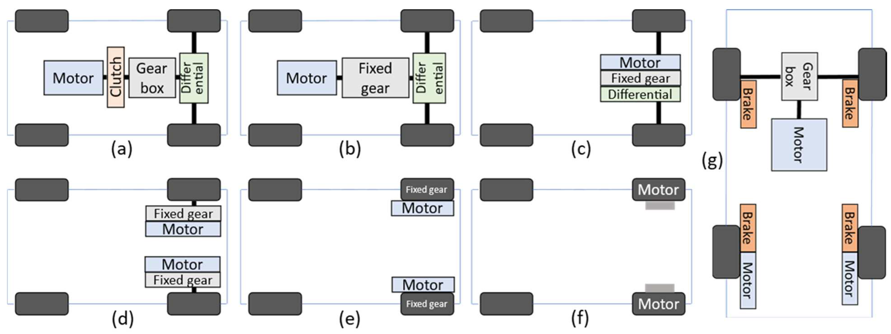

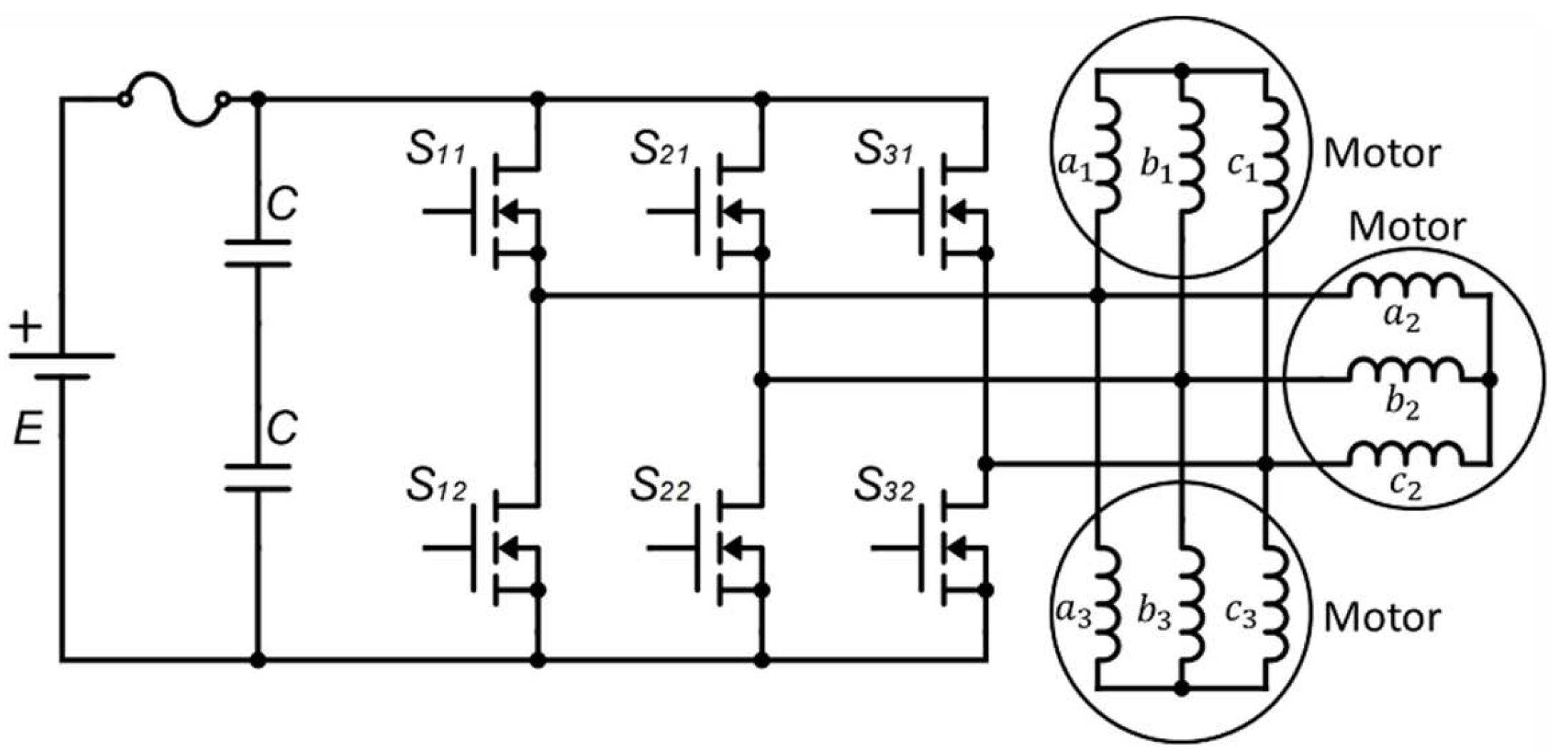


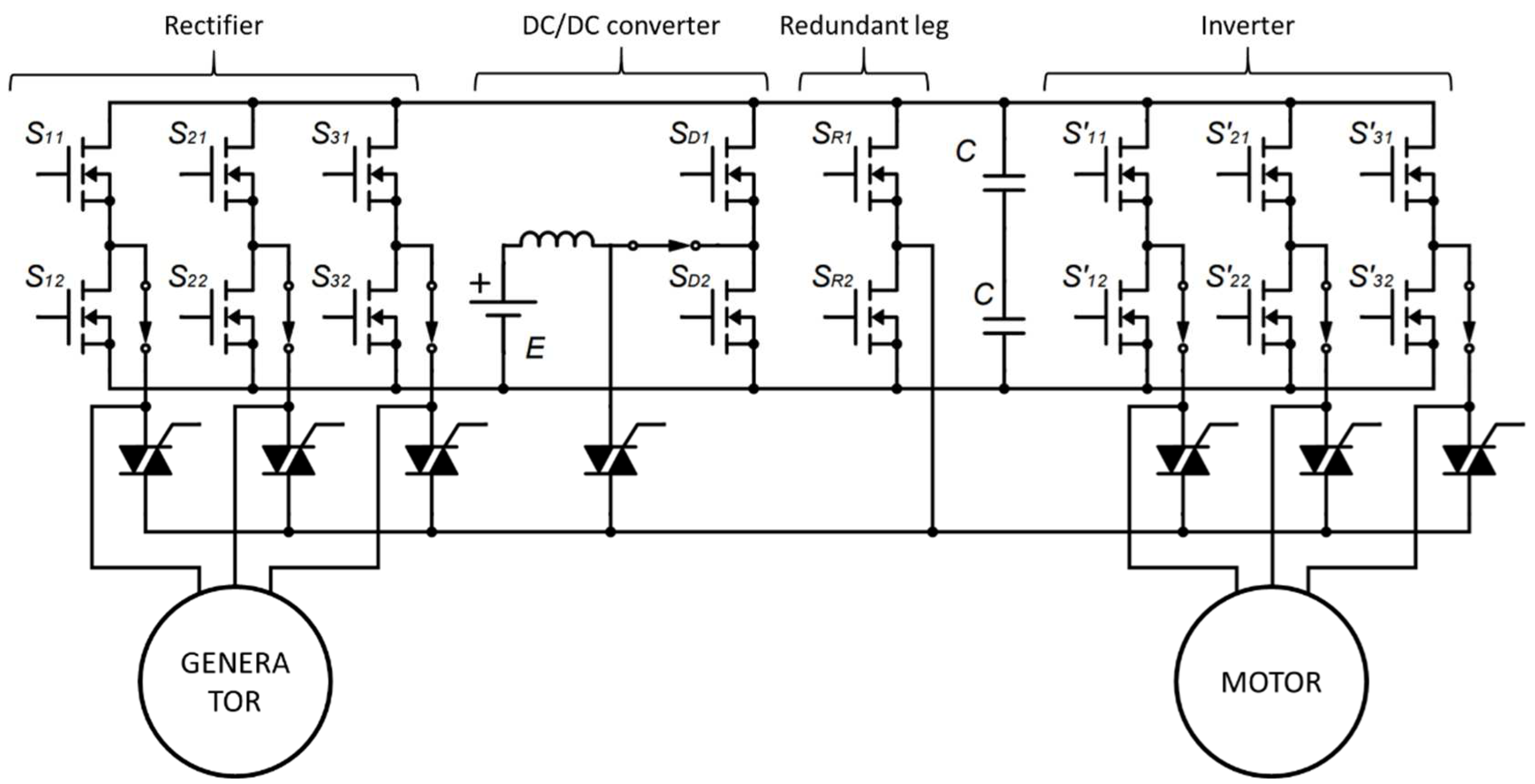


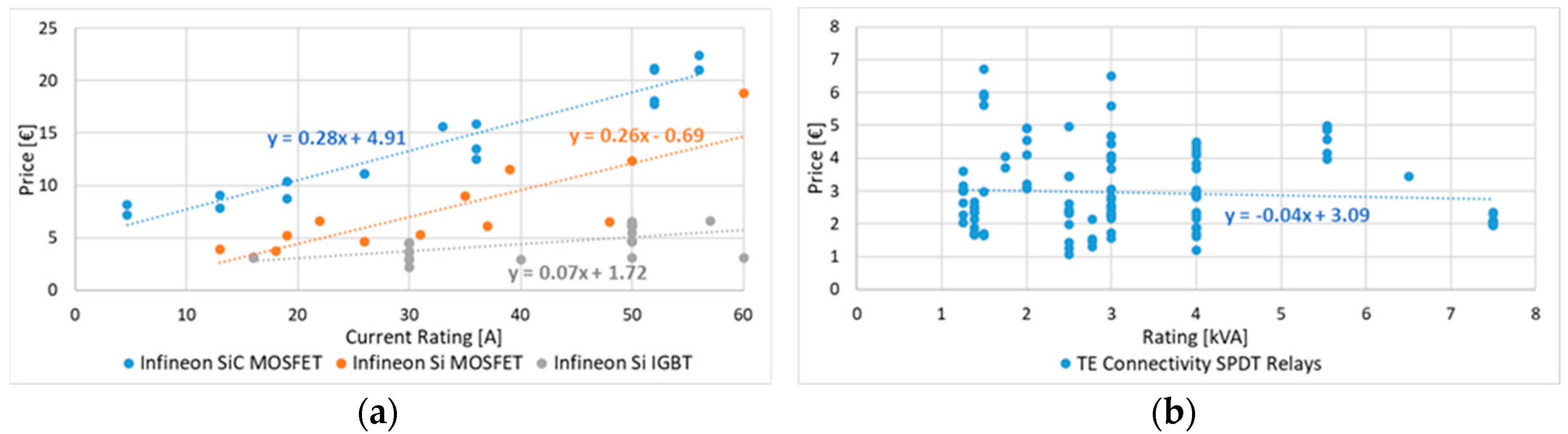


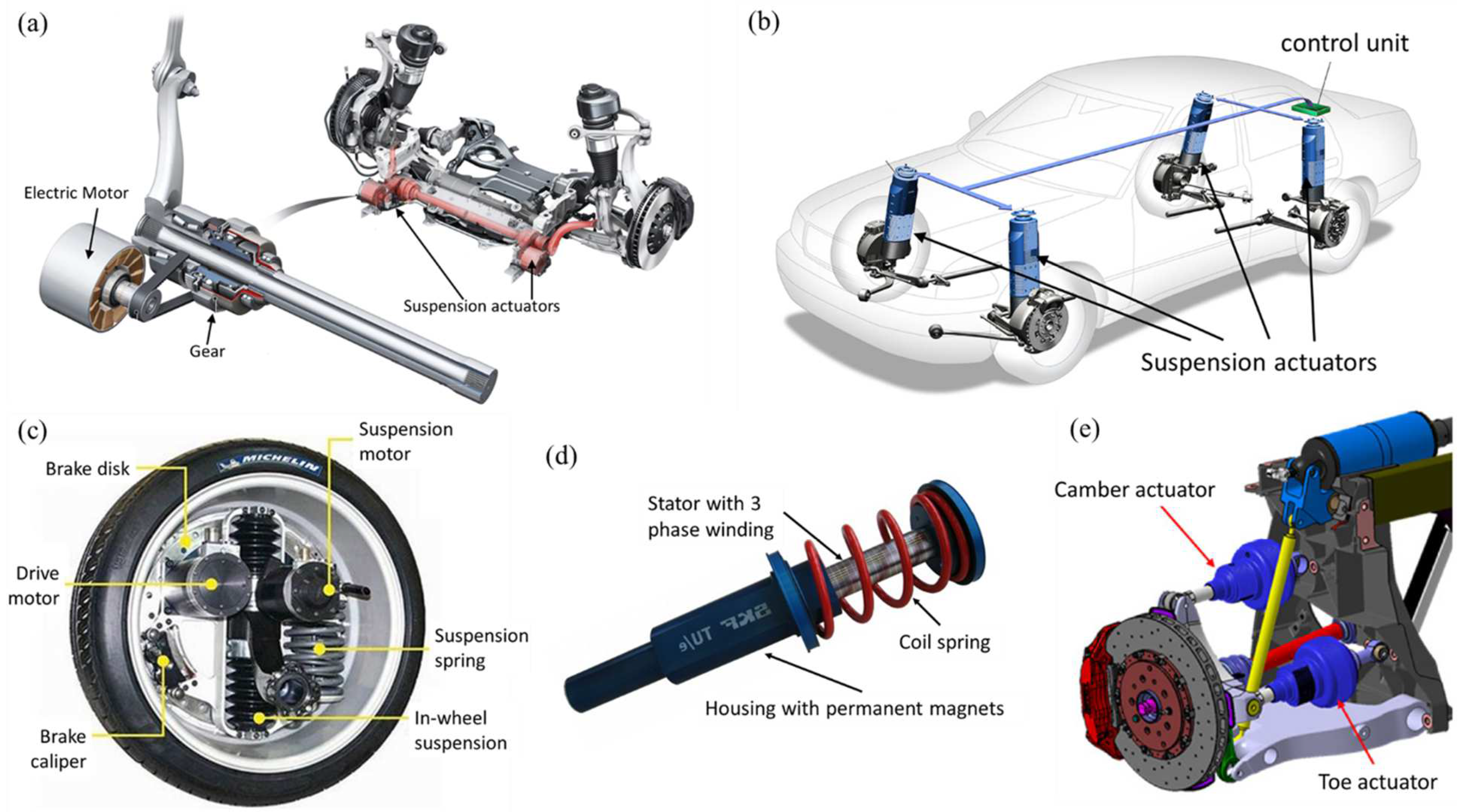