Article

Investigation of a Novel Consequent-Pole Flux-Intensifying Memory Machine

1
School of Electrical Engineering, Southeast University, Nanjing 210096, China
2
School of Mechanical Engineering and Automation, Harbin Institute of Technology (Shenzhen), Shenzhen 518055, China
3
Guangdong Welling Motor Manufacturing Co., Ltd., Foshan 528311, China
4
Midea Group Corporate Research Center, Foshan 528311, China
*
Author to whom correspondence should be addressed.
Energies 2022, 15(15), 5501; https://doi.org/10.3390/en15155501
Submission received: 8 June 2022 / Revised: 20 July 2022 / Accepted: 26 July 2022 / Published: 29 July 2022

Abstract

:
This paper mainly focuses on the investigation and analysis of a novel consequent-pole flux-intensifying memory machine (CP-FIMM). The proposed CP-FIMM exhibits the advantages of a satisfactory flux-regulation range, reduction of the required magnetizing current magnitude, as well as similar torque with much less PM utilization compared to its conventional counterpart. By designing the q-axis flux barriers, the flux-intensifying structure can be realized to enhance the demagnetization withstand capability of the CP-FIMM. The machine topology and operating principle are described. Moreover, the equivalent magnetic circuit model is developed to highlight the performance improvement of the proposed CP-FIMM. Finally, the electromagnetic performance of the proposed CP-FIMM is compared with that of a benchmark conventional FIMM by 2-D and 3-D finite element analysis.

1. Introduction

Permanent magnet synchronous machines (PMSMs) have been extensively applied and industrialized in the fields of vehicle traction, home appliances, and industrial manufacture owing to their merits of high efficiency and high reliability [1,2,3,4,5,6]. However, conventional PMSMs are usually confronted with unchangeable air-gap flux density, which causes limitations in their speed range and further brings some restrictions on the high-speed application. In order to broaden the speed range, flux weakening d-axis currents are conventionally applied to reduce the magnetic field of PMSM at high speed, which unintentionally brings additional copper loss and reduces overall efficiency.
In order to address the problem of unchangeable air-gap flux density, a variable flux memory machine (VFMM) [6,7,8,9,10,11,12,13,14] was proposed and has become a hot research focus. Memory machines utilize low coercive force (LCF) magnets such as AlNiCo, and the magnetization state (MS) can be flexibly adjusted with different transient current pulses with negligible loss. Therefore, VFMM can achieve high efficiency over a wide speed range. The existing VFMMs are divided into DC- [6,7,8] and AC- [9,10,11,12,13,14] magnetized types according to the winding category to provide current pulses. The DC-magnetized VFMMs [6,7,8] usually have LCF magnets on the stator side, and the additional magnetization coils can provide MS manipulation currents conveniently. However, DC-magnetized VFMMs generally suffer from a complicated structure. On the other hand, AC-excited VFMMs [9,10,11,12,13,14,15,16] utilize d-axis current pulses generated by the armature windings to manipulate the MS of LCF magnets, which feature a simple configuration with magnets on the rotor side.
For AC-magnetized VFMMs with a single LCF magnet, flux barriers are often set on the q-axis to realize reverse saliency (Ld > Lq), i.e., a flux-intensifying (FI) property, which can ensure that the maximum torque per ampere (MTPA) operation of the machine happens under the id > 0 situation, and thus can effectively decrease the risk of on-load demagnetization. The first AC-magnetized VFMM is proposed in [11], in which the rotor is characterized by a sandwich structure, including AlNiCo PM, iron core, and non-magnetic material. In [9], a radially magnetized FI VFMM with flux leakage paths is designed and analyzed. The designed machine shows benefits in improving efficiency and extending the range of the torque-speed map. In [13,14,15], spoke-type flux-intensifying VFMMs are proposed. The AlNiCo PMs are tangentially magnetized, which increases the air-gap flux density when fully magnetized, and brings the torque density of the VFMM to a comparable level to a conventional PMSM.
Nevertheless, AC-magnetized VFMMs generally require large amplitudes of magnetizing currents due to the high thickness of LCF magnets, which inevitably leads to an increased requirement for inverter capacity. Consequent-pole (CP) rotor design is a favorable way to reduce magnet usage and magnetization current, as well as maintain torque output at the same time [17,18,19]. Thus, this paper proposes a novel consequent-pole flux-intensifying memory machine (CP-FIMM) to address the above-mentioned problems for AC-magnetized VFMMs. The combination of FI variable-flux characteristics [20,21,22] and a consequent-pole [17,18,19] structure can reduce the amount of AlNiCo magnet, and meanwhile increase the d-axis inductance. Thus, the proposed CP design is advantageous for the reduction of the required magnetizing current magnitude, improvement of magnetic stability and PM utilization simultaneously.
This paper is organized as follows. First, in Section 2, the machine topology and operating principle including the flux regulation principle and magnetic circuit analysis are introduced. In Section 3, the electromagnetic performance of the CP-FIMM and FIMM is investigated and compared based on finite element analysis (FEA) with respect to the open-circuit and on-load performances, as well as magnetization characteristics and efficiency. In Section 4, a 3-D FE analysis is conducted to confirm the validity of the 2-D analysis. Section 5 is devoted to a comprehensive conclusion.

2. Machine Topology and Operating Principle

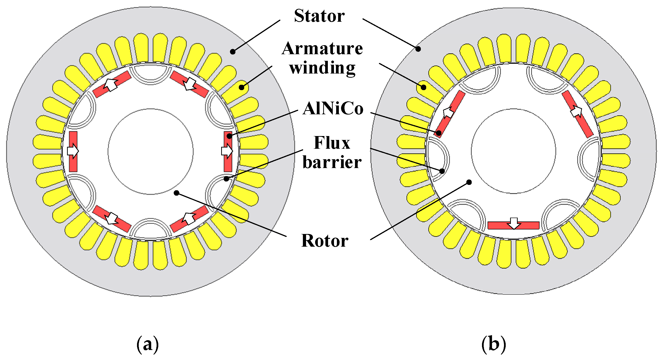
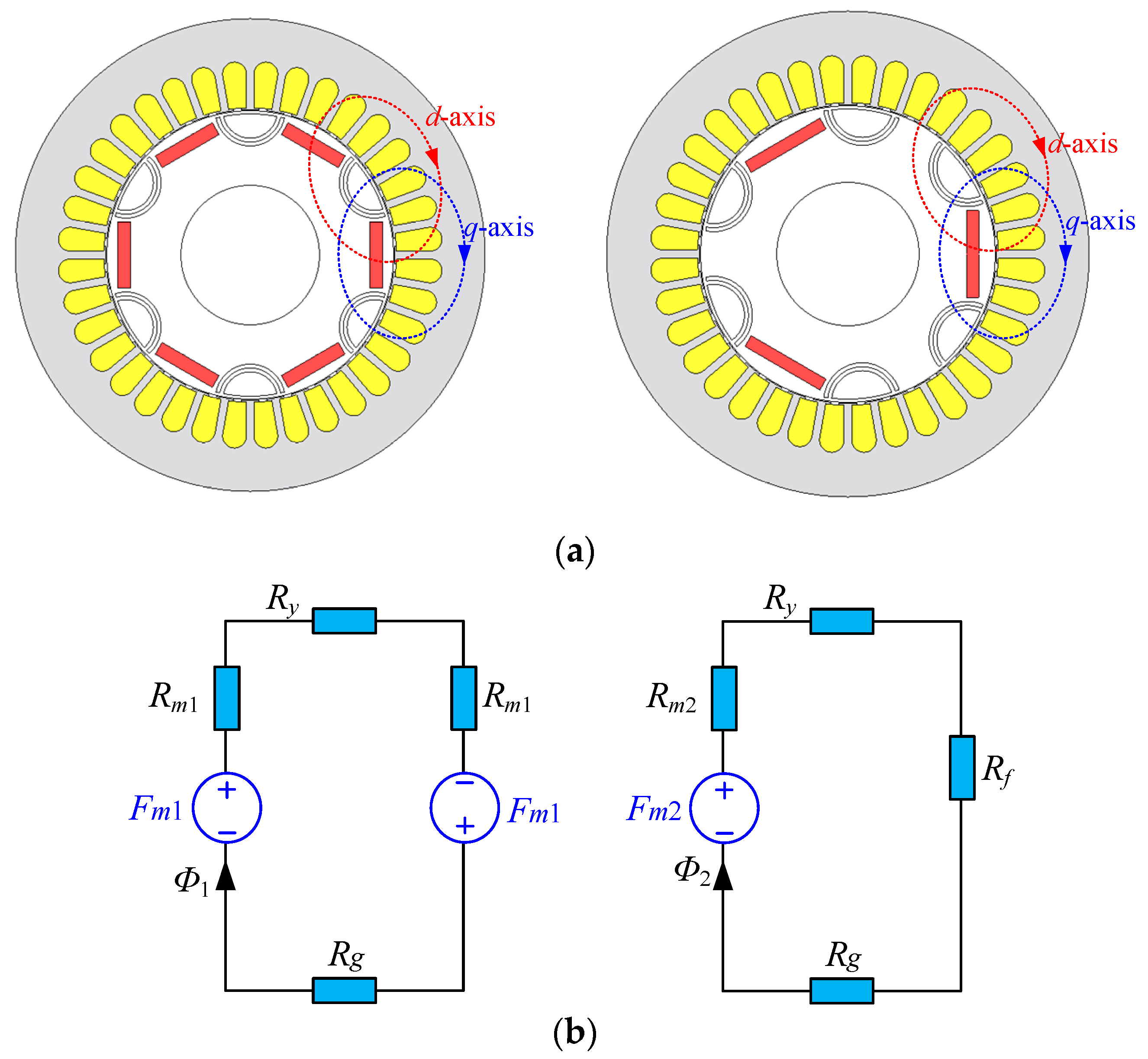
2.1. Machine Topology

Figure 1 shows the machine topologies of conventional FIMM [9] and the proposed CP-FIMM, respectively. Both machines have two layers of q-axis flux barriers in order to reduce q-axis inductance and create the reverse saliency ratio, which is beneficial for the unintentional demagnetization withstand ability. For CP-FIMM, nearly half of the magnet poles are replaced by iron cores, forming a CP structure, which can reduce the usage of AlNiCo PM by approximately 40%. It should be noted that the optimal pole-arc coefficient of the CP-FIMM is slightly larger than 1 in order to achieve higher torque. Table 1 illustrates the key design parameters of the CP-FIMM and FIMM. For a fair comparison, the major design parameters of the two topologies are kept the same except for different PM volumes.

2.2. Flux Regulation Principle

Figure 2 reveals the simplified hysteresis model of the AlNiCo PM. By applying certain transient d-axis current pulses to generate demagnetizing or remagnetizing MMF, the working point of AlNiCo PM will move along the recoil lines and finally stabilizes at the load line. Consequently, the MS of AlNiCo PM can be flexibly changed and maintained according to different operation requirements.
In order to characterize the magnetization state (MS) of the memory machine, the magnetization ratio kmr is defined as
k m r = B r k B r × 100 %
where Br is the remanence of the major hysteresis loop, Brk is the specific remanence corresponding to the specific PM working point on the kth recoil line. The above percentage kmr is then adopted to characterize the magnetization level of the FIMM and CP-FIMM.

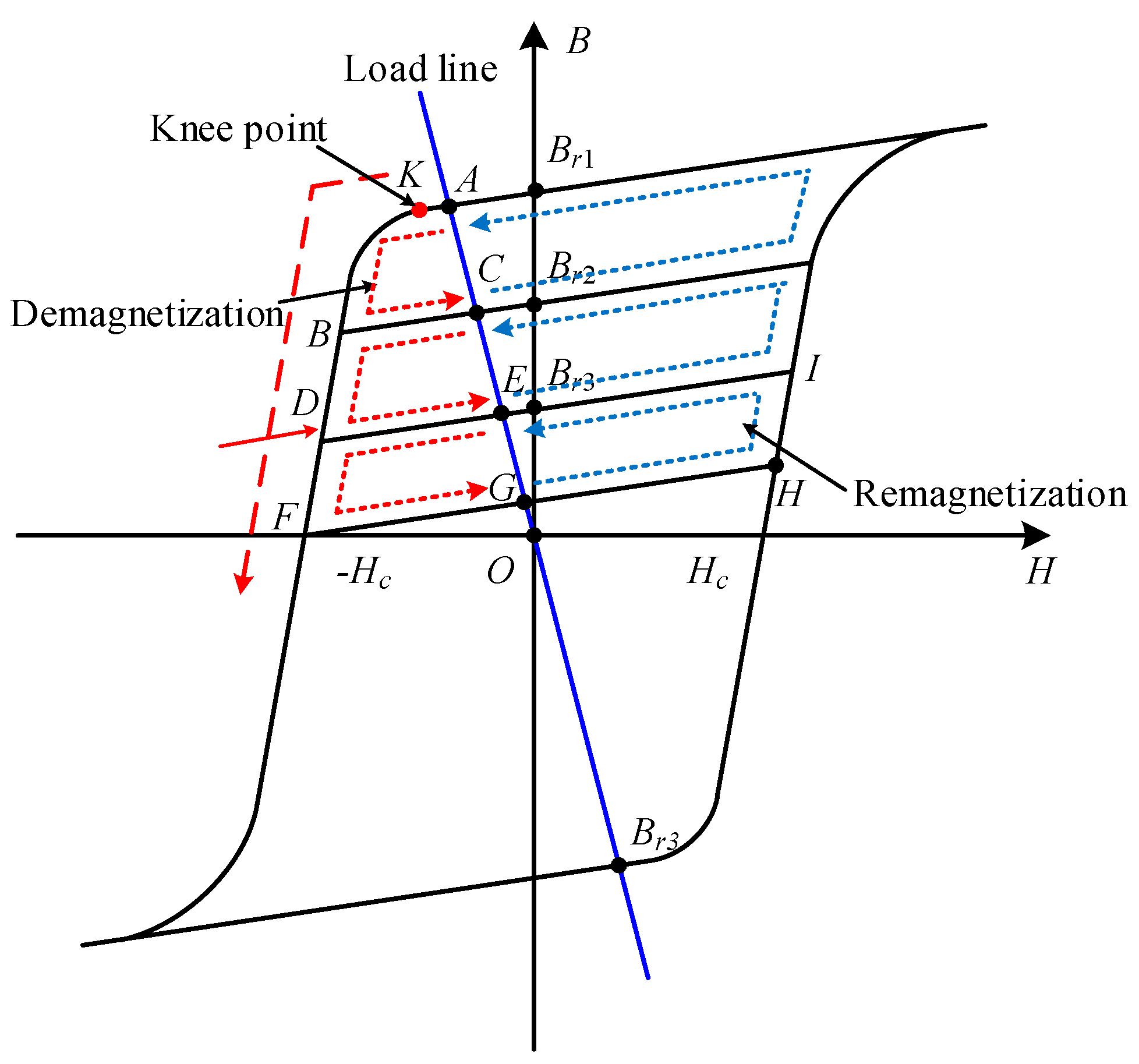
2.3. Magnetic Circuit Analysis
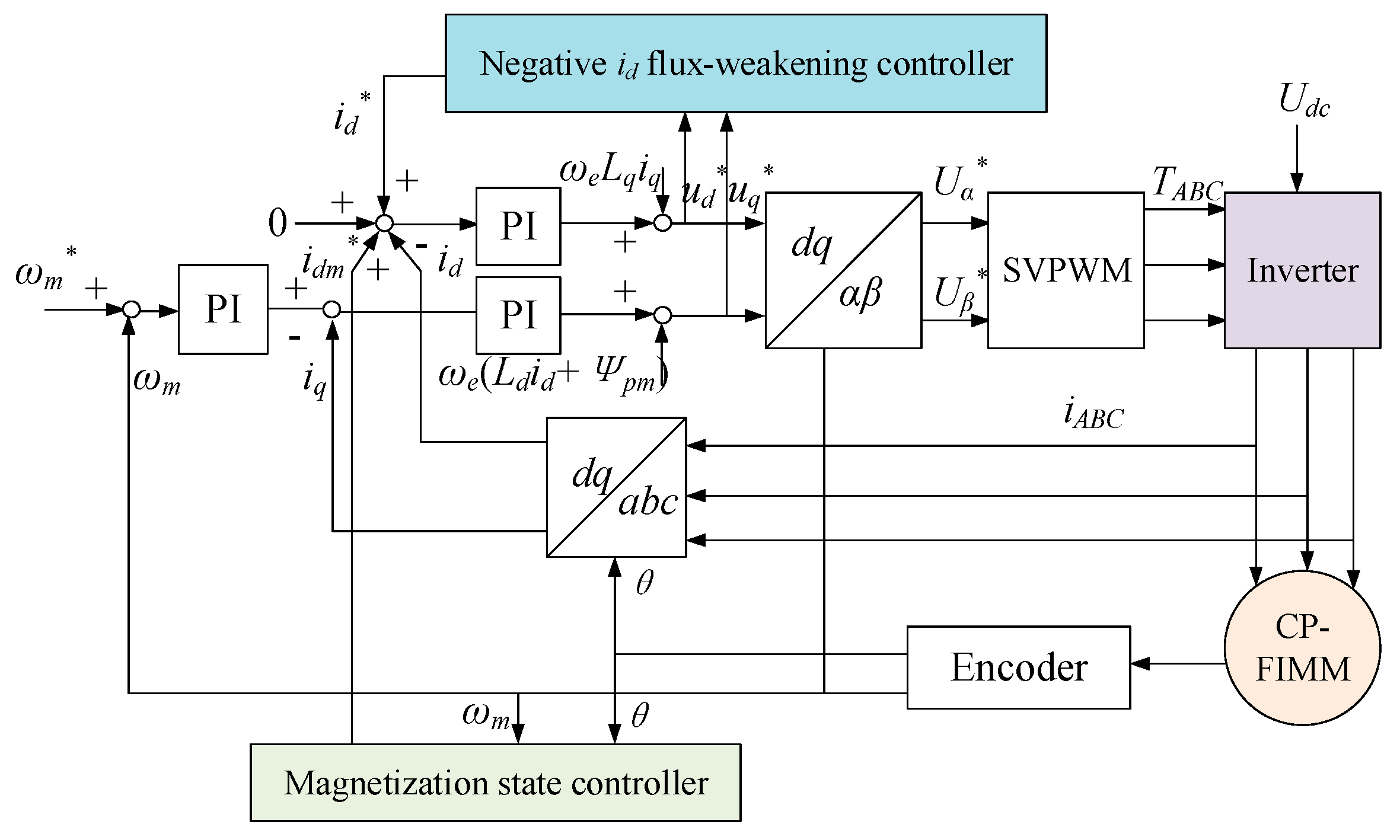
Figure 3a shows the magnetic circuit paths of the FIMM and CP-FIMM, respectively. For the two machines, since double-layer flux barriers are placed on the q-axis, Lq is significantly decreased. Moreover, because the AlNiCo PM usage of CP-FIMM on the d-axis is reduced, the Ld is increased. By realizing the relationship of Ld > Lq, “id > 0” control is adopted for rated MTPA operation to fully utilize the magnet torque and reluctance torque, which can meanwhile reduce the risk of on-load demagnetization.
Figure 3b shows the equivalent d- and q-axis magnetic circuits of the FIMM and CP-FIMM, respectively. The corresponding parameters are listed in Table 2.
The corresponding air-gap flux Φ1 and Φ2 can be illustrated as (2) and (3). Since the volume of a single AlNiCo PM of the CP-FIMM is larger than that of the FIMM, Fm2 is larger than Fm1. Additionally, Rf is smaller than Rm2. Consequently, Φ2 is close to Φ1, which indicates that the electromagnetic performance of the CP-FIMM is close to that of the conventional FIMM.
Φ 1 = 2 F m 1 R y + 2 R m 1 + R g
Φ 2 = F m 2 R y + R m 2 + R g + R f
In addition, the relationship in the flux regulation process can be shown as
Ψ d f = L d i d m
where Ψdf is the required flux linkage to realize MS manipulation, and idm refers to the required MS manipulation current amplitude. It can be deduced that with a smaller amount of AlNiCo PM, the CP-FIMM has a relatively smaller d-axis reluctance as well as a larger Ld. Therefore, lower d-axis magnetomotive force (MMF) is needed for the flux regulation process for CP-FIMM, i.e., lower magnetization currents are required, which can help reduce the capacity of the inverter.

2.4. Control Scheme

Figure 4 shows the control scheme of the proposed CP-FIMM. The MTPA control method for which id > 0 is adopted for its rated operation. Based on the machine operation properties, different MSs are flexibly adjusted by the command of the magnetization state controller. When the speed exceeds the base speed, the negative id flux-weakening method is conducted to offset the PM flux-linkage in order to widen the speed range.

3. Electromagnetic Performance Investigation of the Proposed CP-FIMM

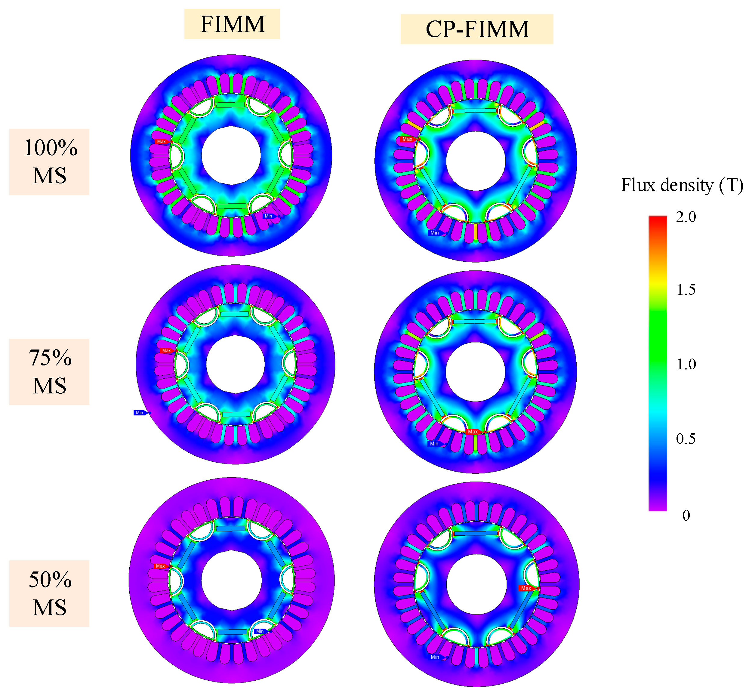
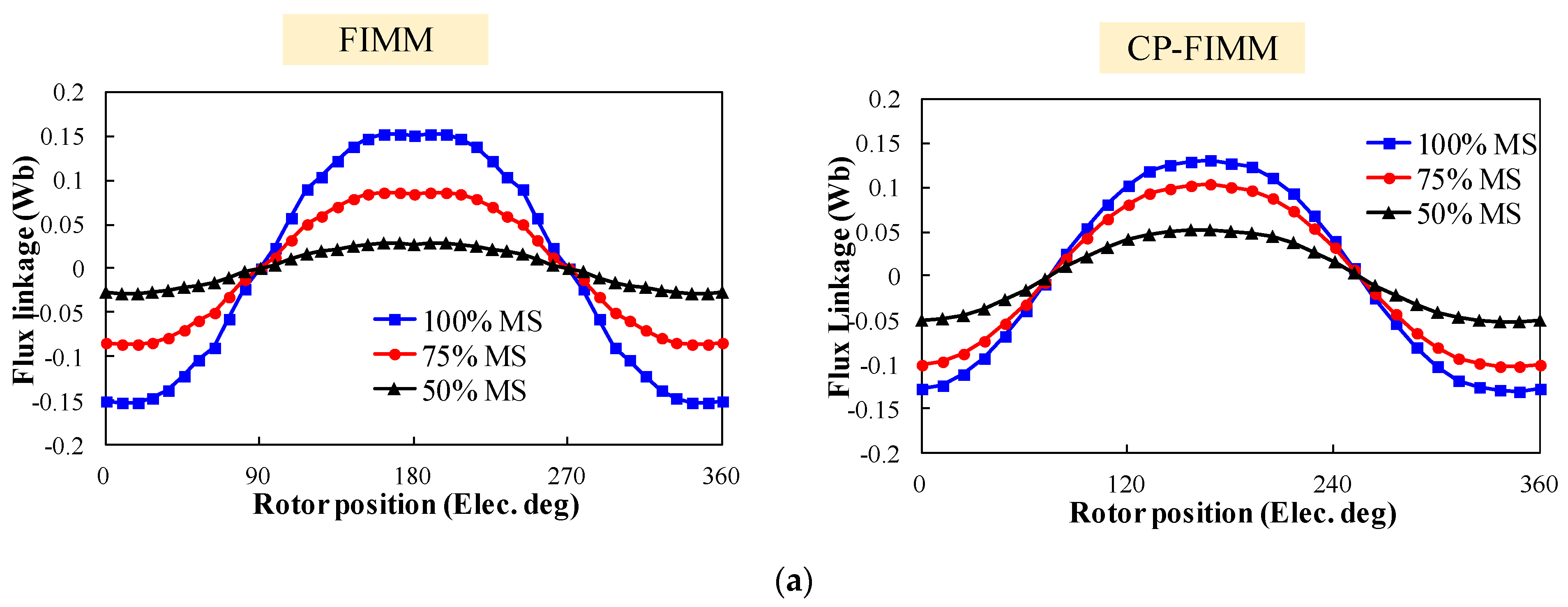
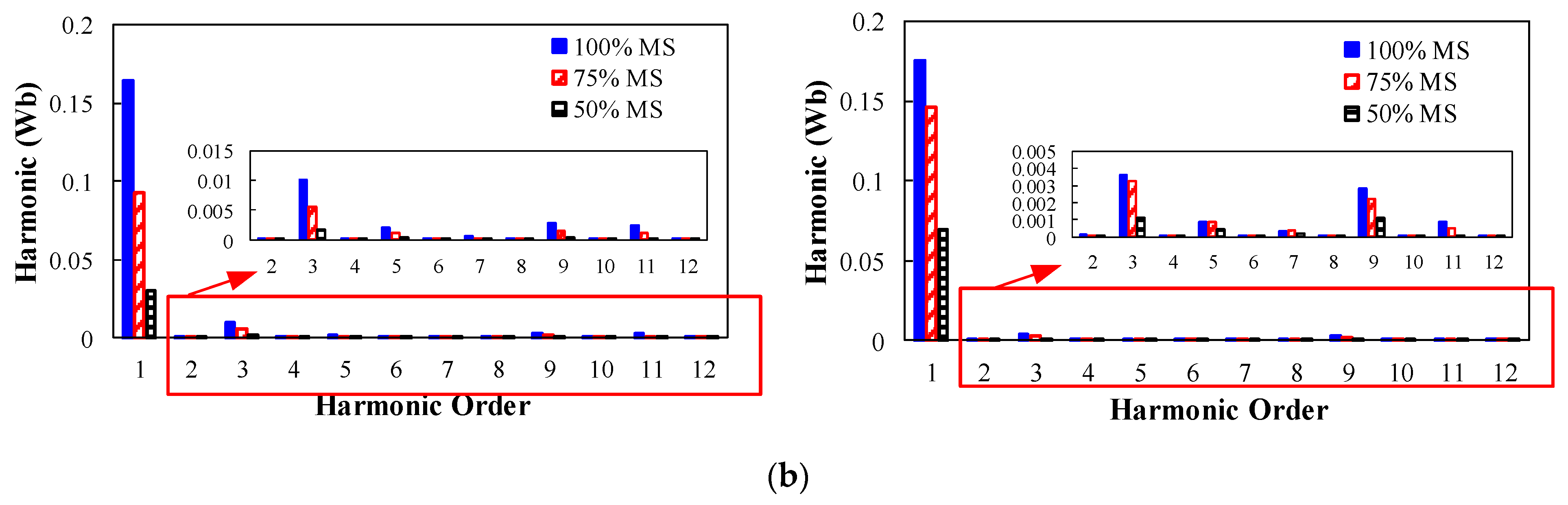
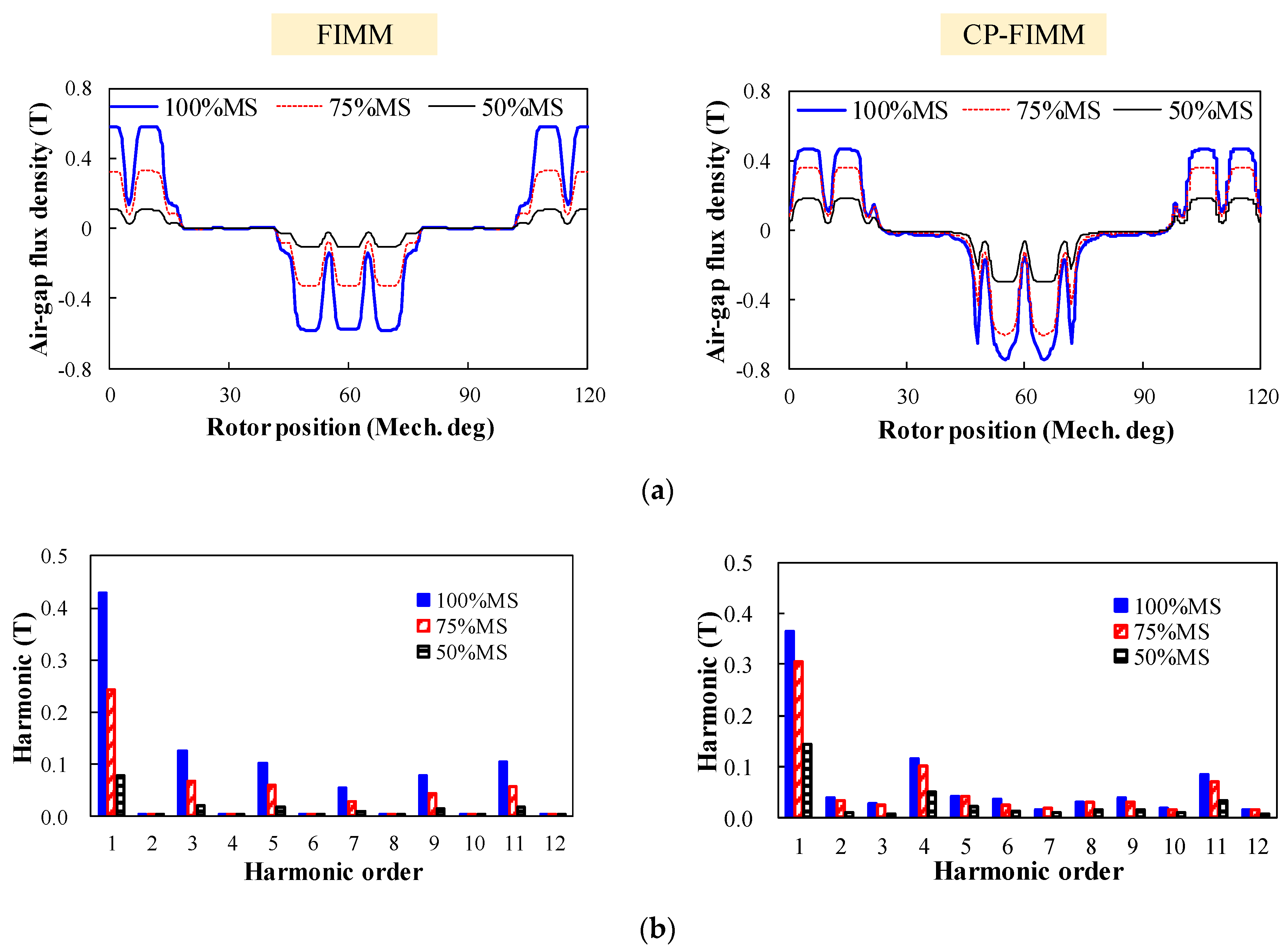
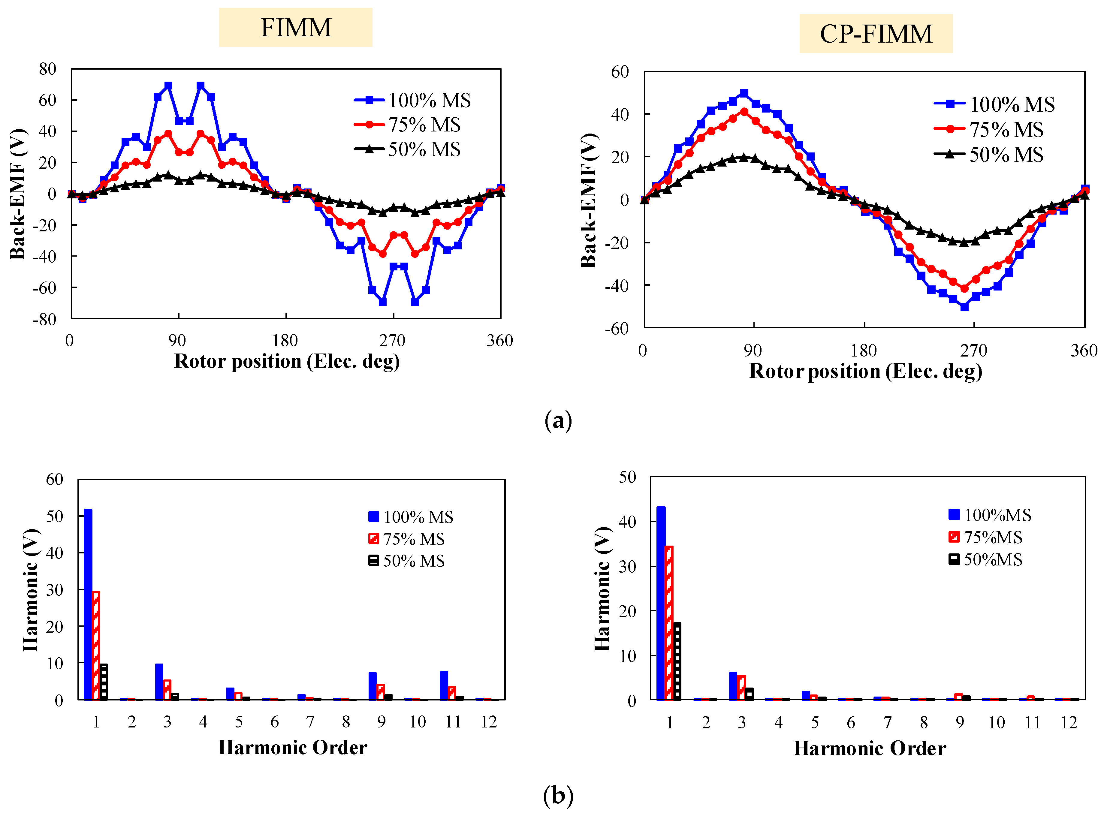
3.1. Open-Circuit Performance

The foregoing CP-FIMM and FIMM machine topologies are designed, and finite element analysis and comparison are conducted based on the JMAG 20.0 package.
Figure 5 shows the flux line distributions of the two machines under different MSs. It can be observed that although a smaller volume of the magnet is utilized in CP-FIMM, similar flux distribution patterns can be found in the two machines. It can also be seen that both topologies can realize variable MSs effectively. Figure 6 shows the flux distributions of FIMM and CP-FIMM under different MSs, respectively. It can be observed that both topologies exhibit excellent flux regulation capability. More severe magnetic saturation can be found around the flux barriers of CP-FIMM due to larger pole-end flux leakage of the AlNiCo PM, which accounts for a smaller air-gap flux density of the CP-FIMM. Moreover, the stator flux density of the CP-FIMM is larger, especially under low MSs, which accounts for more iron loss.
Figure 7 illustrates the flux linkage waveforms and harmonic analysis of FIMM and CP-FIMM under different MSs, respectively. It can be seen that both topologies have excellent MS manipulation capabilities. Besides, the fundamental flux linkage amplitudes of CP-FIMM are slightly lower than those of the conventional FIMM due to its relatively smaller PM usage. The high-order harmonics are zoomed in and shown in Figure 5b. It can be observed that the two machines share similar distribution patterns of harmonics, while the proposed CP-FIMM has a relatively smaller level of harmonics, which is beneficial for the sinusoidal back-EMF waveform and reduction of torque ripple.
Figure 8 shows the air-gap flux density waveforms of the FIMM and CP-FIMM. Due to the existence of iron poles, the air-gap flux density of CP-FIMM shows an asymmetry and has more even-order harmonics. In addition, the fundamental amplitude of air-gap flux density of CP-FIMM is slightly lower than FIMM since 40% of AlNiCo PM is replaced by iron poles. Since more AlNiCo PMs are involved in MS manipulation in the FIMM, the flux densities under 75% and 50% MSs of FIMM are lower than the CP-FIMM, respectively.
The open-circuit back-EMFs as well as harmonic analysis of the CP-FIMM and FIMM under different MSs are shown in Figure 9. It can be observed that the even-order harmonics in air-gap flux are canceled, and the back-EMF of CP-FIMM has a lower fundamental component and a lower total harmonic distortion (THD) with eliminated high-order harmonics.

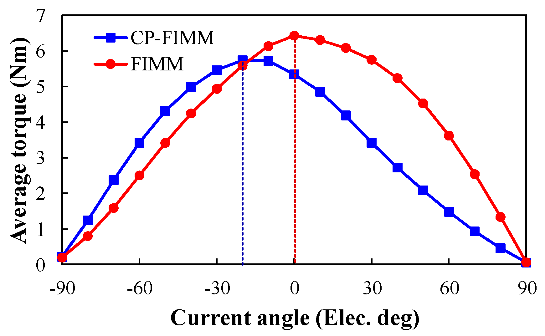
3.2. Torque Performance

Figure 10 shows the average torque of CP-FIMM and FIMM subject to different current angles. It can be seen that the maximum torque of CP-FIMM is acquired with a positive id, which confirms that the FI property, i.e., Ld > Lq, can be well obtained with the design of the CP structure. On the other hand, due to a similar magnetic reluctance of the d- and q-axis, the values of Ld and Lq of FIMM are close to each other, and the FIMM shows negligible saliency.
Figure 11 shows the cogging torque waveforms of the CF-FIMM and FIMM. Since the rotor iron poles serve as half of the magnetic poles, CP-FIMM shares identical cogging torque period with the FIMM. In addition, the two machines have comparable cogging torque amplitude.
The torque characteristics of the two machines are compared in Table 3. It can be observed that the proposed CP-FIMM can achieve 93.49% of the average torque by reducing 40% of AlNiCo PM volume, and has a larger PM utilization rate. Due to the limitation of cost and restriction on PM volume, the torque of CP-FIMM is slightly lower. However, it should be noted that with a slightly larger PM volume, the CP-FIMM is able to achieve the same torque compared with the FIMM. Moreover, the CP-FIMM has a smaller torque ripple than the FIMM owing to a more sinusoidal back-EMF.

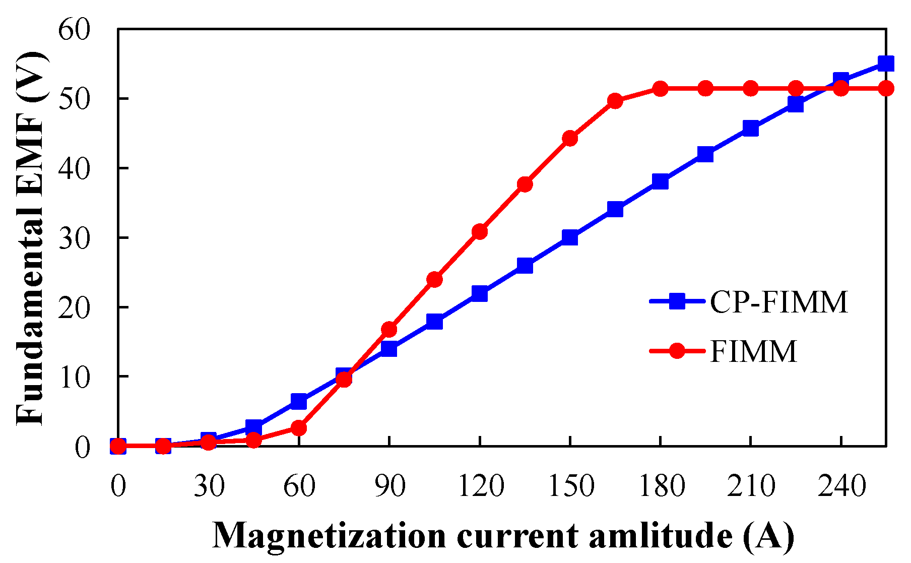
3.3. Flux Regulation Performance

The flux regulation characteristics of the CP-FIMM and FIMM are analyzed based on the required transient current amplitude to change the fundamental open-circuit back-EMF. Figure 12 and Figure 13 show the waveforms of fundamental back-EMF versus different flux regulation current amplitude of the two machines. It can be seen that compared with the conventional FIMM, it is significantly easier to magnetize or demagnetize the CP-FIMM, which is consistent with the foregoing analyses. Consequently, with a smaller demagnetizing current amplitude, the required inverter capacity can be reduced.

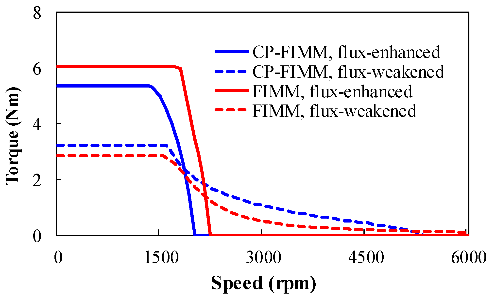
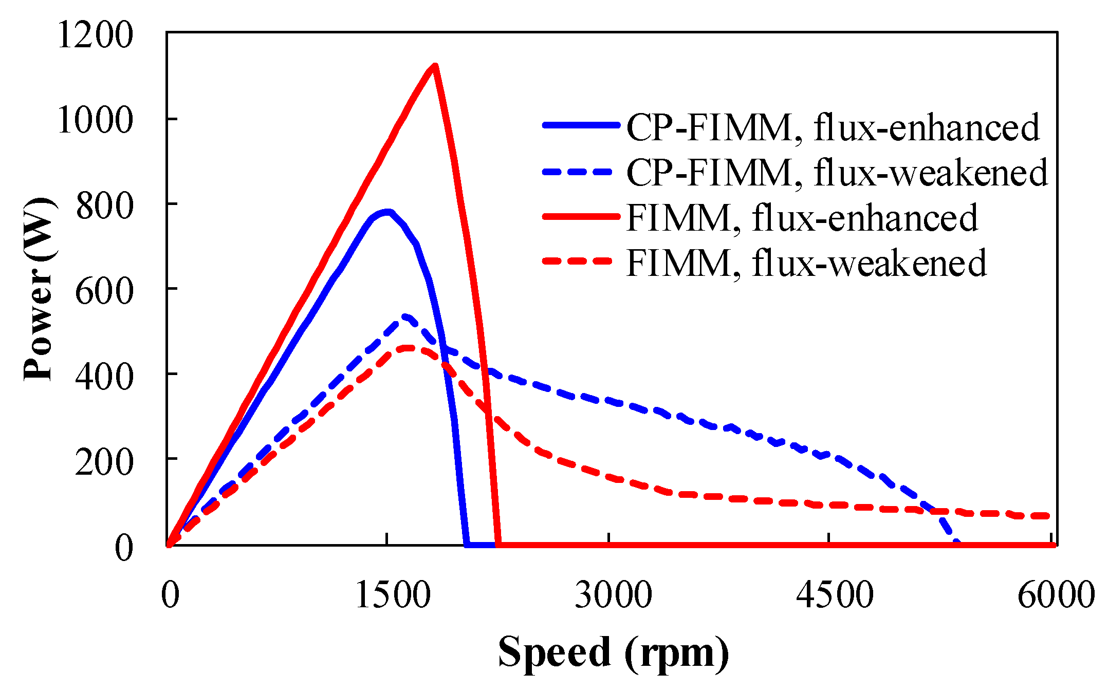
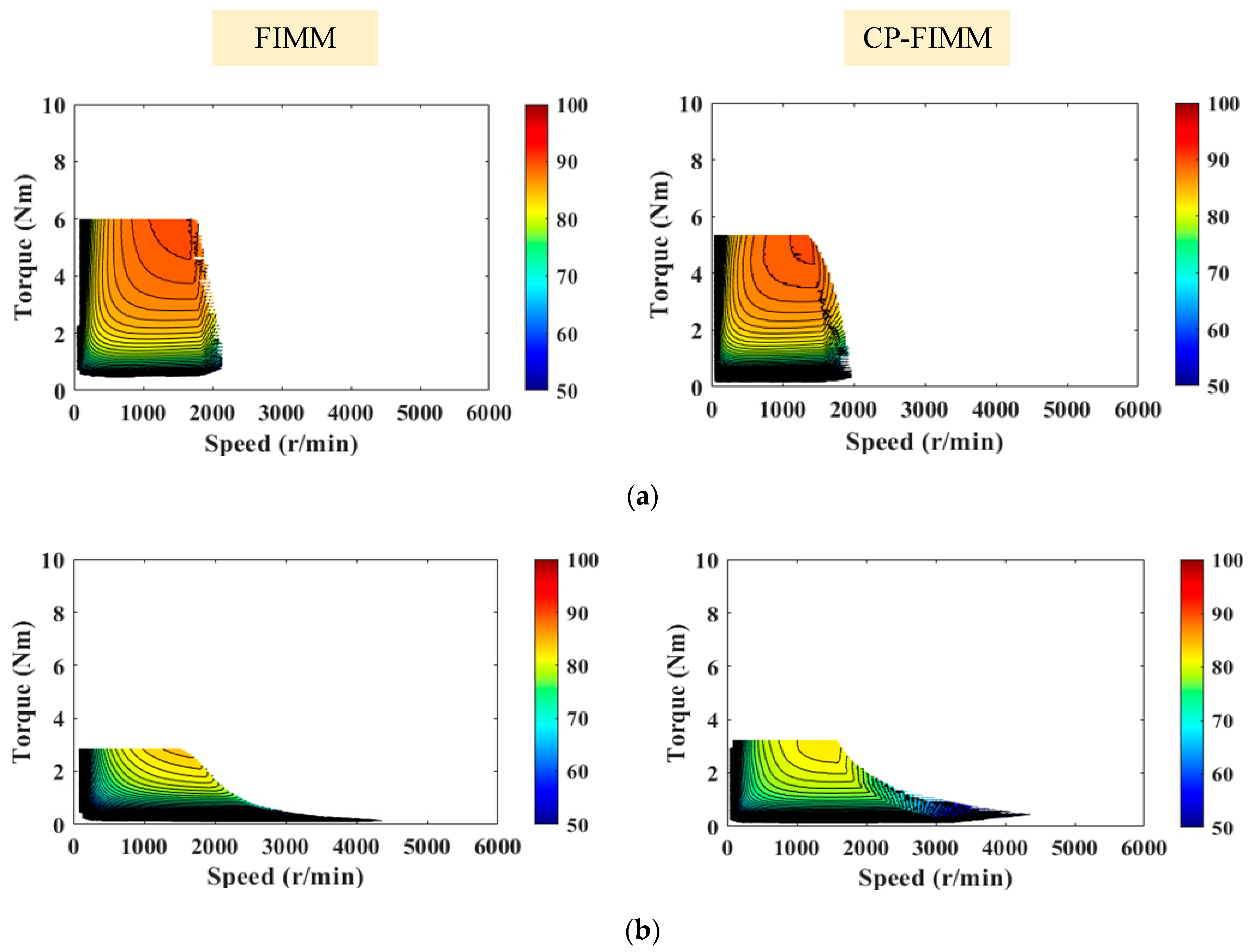
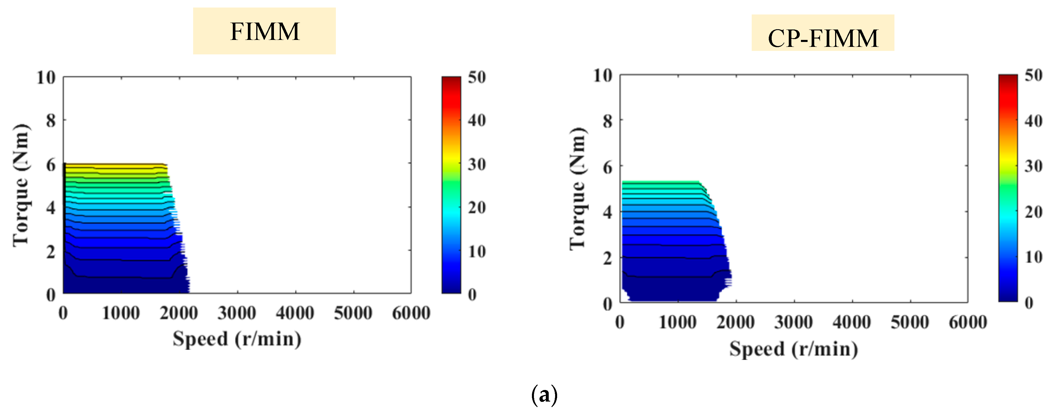
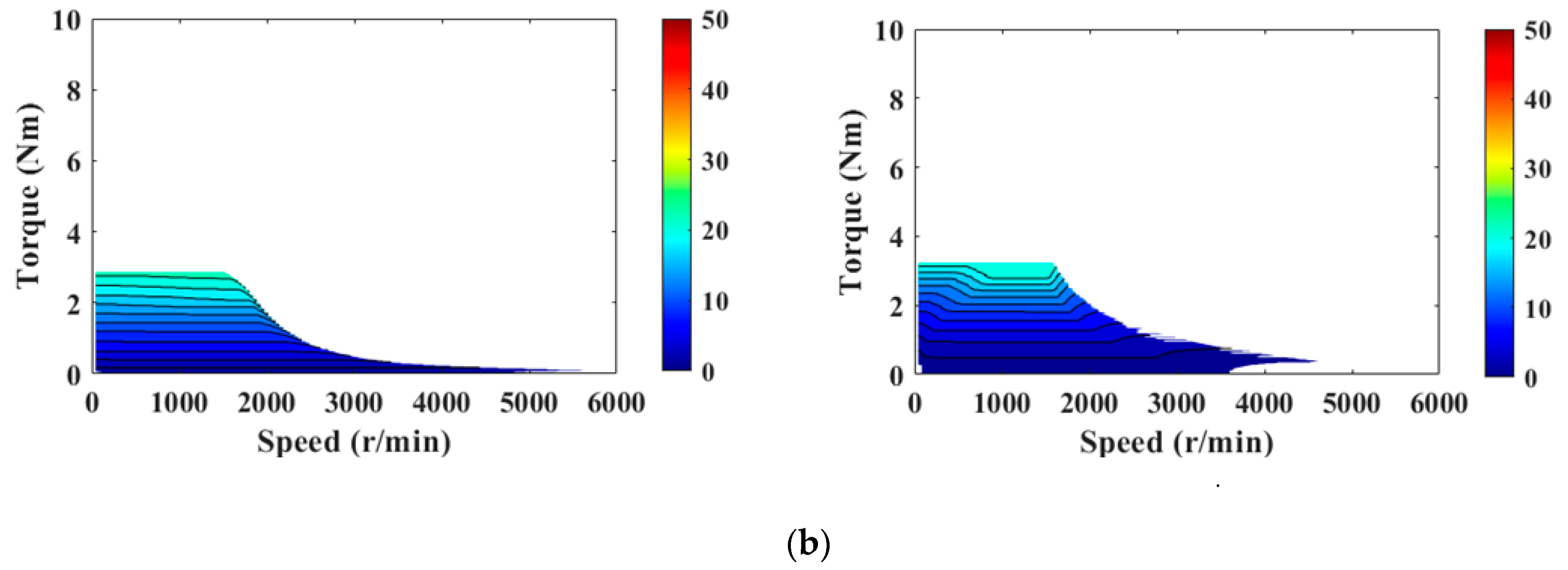
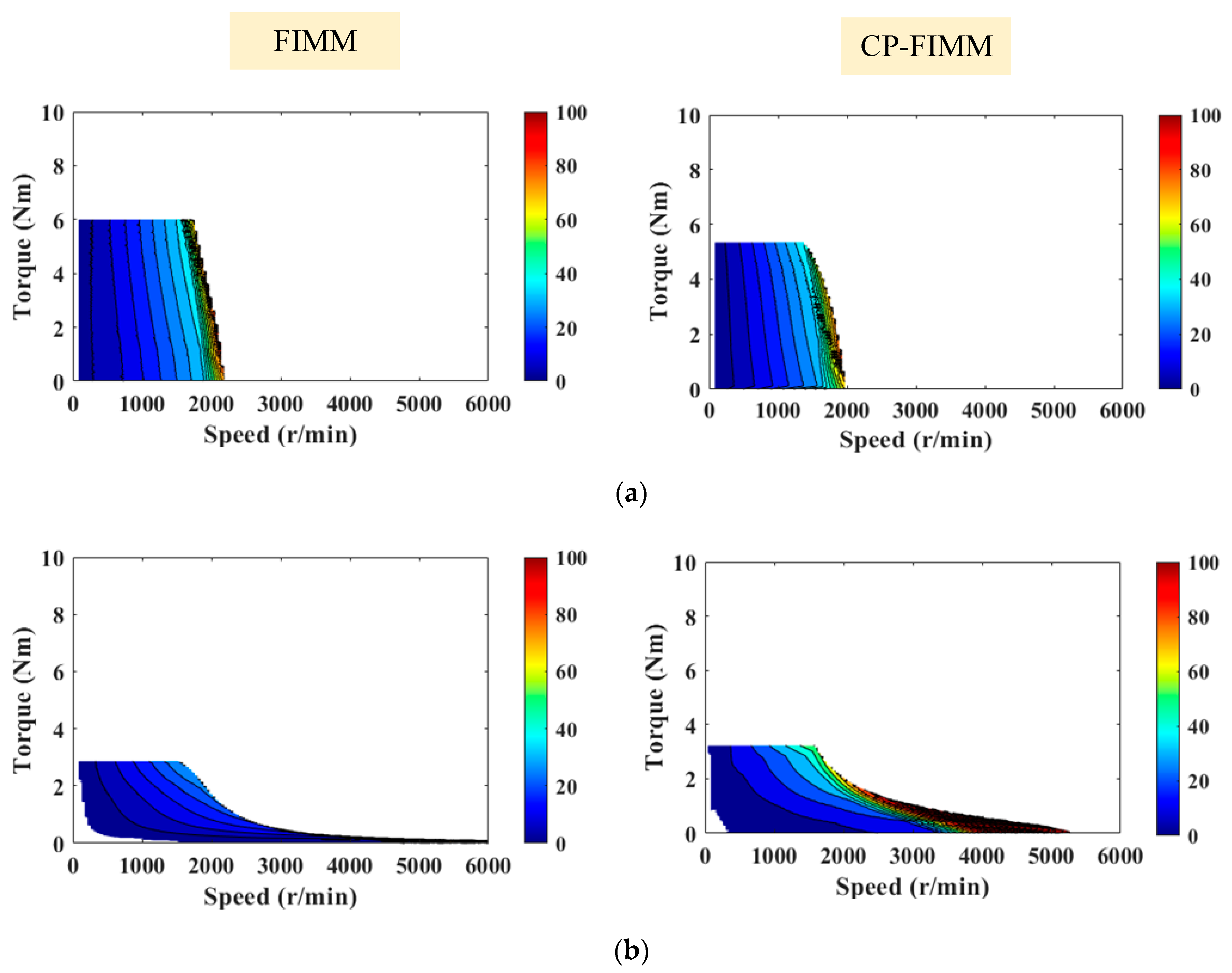
3.4. External Characteristics

The external characteristics of the two machines are acquired based on the control method in Figure 4, and the corresponding waveforms are shown in Figure 14 and Figure 15, respectively. It can be seen that the CP-FIMM has a relatively smaller torque and electromagnetic power under a flux-enhanced state, which is mainly due to the smaller usage of the magnet. On the other hand, the CP-FIMM has a larger output power and torque under the flux-weakened state, which is compromised with a lower maximum speed.

3.5. Efficiency

Figure 16 shows the efficiency maps of the proposed CP-FIMM and FIMM under different MSs, respectively. It can be found that the CP-FIMM can realize a wide speed range with high overall efficiency. Additionally, the CP-FIMM shows a relatively smaller overall efficiency than the conventional counterpart.
Figure 17 and Figure 18 show the copper and iron loss maps of the two machines under different MSs, respectively. It can be seen that the two machines share similar copper loss patterns and the CP-FIMM has a lower copper loss under high-speed operation region due to better flux-weakening performance. On the other hand, the CP-FIMM has a larger iron loss under high-speed operation, which is due to the larger flux density distribution in the stator, which can be found in Figure 6. As a result, the efficiency of CP-FIMM is slightly lower than the FIMM, especially under the flux-weakened state.

4. Three-Dimensional FE analysis

In order to further validate the above 2-D FE analysis, 3-D models are built in Figure 19 according to the stack lengths and the torque performance of the two machines are analyzed. The corresponding results are shown in Figure 20 and Table 4. It can be seen that the average torque and torque ripple results are close between the 2-D and 3-D FE analyses, which confirms the validity of the foregoing analysis.

5. Conclusions

In this paper, a novel CP-FIMM is developed and analyzed. The flux regulation and operating principle of the CP-FIMM are firstly described based on the simplified hysteresis model and equivalent magnetic circuit. It is deduced that the torque capability of CP-FIMM is close to that of the conventional FIMM, and requires a lower level of magnetization currents due to a larger d-axis inductance. Then, the electromagnetic performance of CP-FIMM and a benchmark conventional FIMM are investigated and compared based on the FE method. It is found that the CP-FIMM can realize similar torque output to the conventional FIMM with an approximate 60% reduction in PM volume. Additionally, the required magnetizing current of CP-FIMM can be significantly reduced due to a larger d-axis inductance. The efficiency distribution patterns of the two machines are similar, with a slightly lower efficiency of CP-FIMM. Finally, a 3-D FE analysis is carried out to confirm the validity of the 2-D analysis.

Author Contributions

Conceptualization, R.T. and H.Y.; Methodology, H.L. and H.Z.; Software, D.W. and M.Y.; Project administration. L.C. and W.C. All authors have read and agreed to the published version of the manuscript.

Funding

This work was jointly supported in part by the National Natural Science Foundations of China (52037002 and 52077033), the Key R&D Program of Jiangsu Province (BE2021052) and the “Thousand Talents Plan” Project of Jiangxi Province (jsxq2020102088), in part by the Fundamental Research Funds for the Central Universities (2242017K41003), in part by Supported by the “SEU Zhishan scholars” Program of Southeast University (2242019R40042), and in part supported by “the Excellence Project Funds of Southeast University”.

Institutional Review Board Statement

Not applicable.

Informed Consent Statement

Not applicable.

Data Availability Statement

Data sharing not applicable.

Conflicts of Interest

The authors declare no conflict of interest.

References

  1. Wu, L.; Tian, Z. Analysis of a Triple-Stator Axial-Flux Spoke-Type Permanent Magnet Vernier Machine. IEEE Trans. Ind. Appl. 2022. [Google Scholar] [CrossRef]
  2. Liu, C.; Xu, Y.; Zou, J.; Yu, G.; Zhuo, L. Permanent Magnet Shape Optimization Method for PMSM Air Gap Flux Density Harmonics Reduction. CES Trans. Electr. Mach. Syst. 2021, 5, 284–290. [Google Scholar] [CrossRef]
  3. Zhao, W.; Yang, Z.; Liu, Y.; Wang, X. Analysis of a Novel Surface-Mounted Permanent Magnet Motor with Hybrid Magnets for Low Cost and Low Torque Pulsation. IEEE Trans. Magn. 2021, 57, 8104804. [Google Scholar] [CrossRef]
  4. Paul, S.; Chang, J. Fast Model-Based Design of High Performance Permanent Magnet Machine for Next Generation Electric Propulsion for Urban Aerial Vehicle Application. CES Trans. Electr. Mach. Syst. 2021, 5, 143–151. [Google Scholar] [CrossRef]
  5. Oka, T.; Hasebe, S.; Ogawa, J.; Fukui, S.; Nakano, T.; Yokoyama, K.; Miryala, M.; Sakai, N.; Murakami, M. Magnetizing Technique for Permanent Magnets in IPM Motor Rotors Using HTS Bulk Magnet. IEEE Trans. Appl. Supercond. 2020, 30, 5206304. [Google Scholar] [CrossRef]
  6. Cheng, M.; Sun, L.; Buja, G.; Song, L. Advanced Electrical Machines and Machine-Based Systems for Electric and Hybrid Vehicles. Energies 2015, 8, 9541–9564. [Google Scholar] [CrossRef] [Green Version]
  7. Yang, H.; Lin, H.; Zhu, Z.Q.; Lyu, S.; Liu, Y. Design and Analysis of Novel Asymmetric-Stator-Pole Flux Reversal PM Machine. IEEE Trans. Ind. Electron. 2020, 67, 101–114. [Google Scholar] [CrossRef] [Green Version]
  8. Zhu, X.; Xiang, Z.; Quan, L.; Wu, W.; Du, Y. Multimode Optimization Design Methodology for a Flux-Controllable Stator Permanent Magnet Memory Motor Considering Driving Cycles. IEEE Trans. Ind. Electron. 2018, 65, 5353–5366. [Google Scholar] [CrossRef]
  9. Limsuwan, N.; Kato, T.; Akatsu, K.; Lorenz, R.D. Design and Evaluation of a Variable-Flux Flux-Intensifying Interior Permanent-Magnet Machine. IEEE Trans. Ind. Appl. 2014, 50, 1015–1024. [Google Scholar] [CrossRef]
  10. Xu, H.; Li, J.; Chen, J.; Lu, Y.; Ge, M. Analysis of a Hybrid Permanent Magnet Variable-Flux Machine for Electric Vehicle Tractions Considering Magnetizing and Demagnetizing Current. IEEE Trans. Ind. Appl. 2021, 57, 5983–5992. [Google Scholar] [CrossRef]
  11. Ostovic, V. Memory Motors-a New Class of Controllable Flux PM Machines for a True Wide Speed Operation. In Proceedings of the Industry Applications Conference, 36th IAS Annual Meeting, Chicago, IL, USA, 30 September 2001–4 October 2001; pp. 2577–2584. [Google Scholar]
  12. Xie, Y.; Ning, Z.; Ma, Z.; Cai, W.; Wei, J. Design and Research of Novel Variable Flux Memory Motor with Series Hybrid Magnets. In Proceedings of the 2020 23rd International Conference on Electrical Machines and Systems (ICEMS), Hamamatsu, Japan, 24–27 November 2020; pp. 2142–2147. [Google Scholar]
  13. Sun, A.; Li, J.; Qu, R.; Chen, J.; Lu, H. Rotor Design Considerations for a Variable-Flux Flux-Intensifying Interior Permanent Magnet Machine with Improved Torque Quality and Reduced Magnetization Current. In Proceedings of the 2015 IEEE Energy Conversion Congress and Exposition (ECCE), Montreal, QC, Canada, 20–24 September 2005; pp. 784–790. [Google Scholar]
  14. Lu, Y.; Li, J.; Qu, R.; Sun, A.; Fang, H. A Method to Improve Torque Density and Reduce Magnetization Current in a Variable-Flux Flux-Intensifying Interior Permanent Magnet Machine. In Proceedings of the 2016 IEEE Vehicle Power and Propulsion Conference (VPPC), Hangzhou, China, 17–20 October 2016. [Google Scholar]
  15. Ibrahim, M.; Masisi, L.; Pillay, P. Design of Variable-Flux Permanent-Magnet Machines Using Alnico Magnets. IEEE Trans. Ind. Appl. 2015, 51, 4482–4491. [Google Scholar] [CrossRef]
  16. Qiao, G.; Liu, Y.; Zheng, P.; Chen, J.; Zhang, S.; Wang, M. Analysis of Magnetic Properties of AlNiCo and Methods of Mitigating Dynamic Voltage Limits in the Combined-Magnetic-Pole Memory Motor. In Proceedings of the 21st International Conference on Electrical Machines and Systems (ICEMS), Jeju, Korea, 7–10 October 2018; pp. 1175–1180. [Google Scholar]
  17. Wei, F.; Zhu, Z.Q.; Sun, X.; Yan, L.; Qi, J. Investigation of Asymmetric Consequent-Pole Hybrid Excited Flux Reversal Machines. IEEE Trans. Ind. Appl. 2022, 58, 3434–3446. [Google Scholar] [CrossRef]
  18. Yang, H.; Lin, H.; Li, H.; Lyu, S. Analysis of Consequent-Pole Flux Reversal Permanent Magnet Machine with Biased Flux Modulation Theory. IEEE Trans. Ind. Electron. 2020, 67, 2107–2121. [Google Scholar] [CrossRef] [Green Version]
  19. Qi, J.; Zhu, Z.Q.; Li, Y.; Jewell, G.W.; Hilton, C. Effect of Pole Shaping on Torque Characteristics of Consequent Pole PM Machines. In Proceedings of the IEEE International Electric Machines & Drives Conference (IEMDC), Hartford, CT, USA, 17–20 May 2021. [Google Scholar]
  20. Zhu, X.; Yang, S.; Du, Y.; Xiang, Z.; Xu, L. Electromagnetic Performance Analysis and Verification of a New Flux-Intensifying Permanent Magnet Brushless Motor with Two-Layer Segmented Permanent Magnets. IEEE Trans. Magn. 2016, 52, 8204004. [Google Scholar] [CrossRef]
  21. Ngo, D.; Hsieh, M.; Huynh, T.A. Torque Enhancement for a Novel Flux Intensifying PMa-SynRM Using Surface-Inset Permanent Magnet. IEEE Trans. Magn. 2019, 55, 8106108. [Google Scholar] [CrossRef]
  22. Liu, F.; Quan, L.; Zhu, X.; Xiang, Z.; Wu, W. Investigation of Reverse Saliency Characteristic in Flux-Intensifying Hybrid Permanent Magnet Motor Considering Various Operation Conditions. In Proceedings of the 2018 IEEE International Conference on Applied Superconductivity and Electromagnetic Devices (ASEMD), Tianjin, China, 15–18 April 2018; pp. 1–2. [Google Scholar]
Figure 1. Machine topology. (a) FIMM, (b) CP-FIMM.
Energies 15 05501 g001
Figure 2. The simplified hysteresis model of the AlNiCo PM.
Energies 15 05501 g002
Figure 3. Magnetic circuits of FIMM and CP-FIMM, (a) d- and q-axis; (b) equivalent magnetic circuit of d-axis.
Energies 15 05501 g003
Figure 4. Control scheme of the CP-FIMM.
Energies 15 05501 g004
Figure 5. Flux line distributions under different MSs. (a) FIMM; (b) CP-FIMM.
Energies 15 05501 g005
Figure 6. Flux density distributions of the two machines under different MSs.
Energies 15 05501 g006
Figure 7. Flux linkage of the two machines. (a) Waveforms; (b) harmonic spectra.
Energies 15 05501 g007aEnergies 15 05501 g007b
Figure 8. Air-gap flux density of the two machines under different MSs. (a) Waveforms, (b) spectra.
Energies 15 05501 g008
Figure 9. Back-EMF waveforms and harmonic analysis CP-FIMM and FIMM under different MSs. (a) Waveforms; (b) spectra.
Energies 15 05501 g009
Figure 10. Average torque versus current angle plots of the CP-FIMM and FIMM.
Energies 15 05501 g010
Figure 11. Cogging torque waveforms.
Energies 15 05501 g011
Figure 12. Fundamental back-EMF versus demagnetization current.
Energies 15 05501 g012
Figure 13. Fundamental back-EMF versus magnetization current.
Energies 15 05501 g013
Figure 14. Torque-speed waveforms of the CP-FIMM and FIMM under different MSs.
Energies 15 05501 g014
Figure 15. Power-speed waveforms of the CP-FIMM and FIMM under different MSs.
Energies 15 05501 g015
Figure 16. Efficiency maps of FIMM and CP-FIMM. (a) Flux-enhanced; (b) flux-weakened.
Energies 15 05501 g016
Figure 17. Copper loss maps of FIMM and CP-FIMM. (a) Flux-enhanced; (b) flux-weakened.
Energies 15 05501 g017aEnergies 15 05501 g017b
Figure 18. Iron loss maps of FIMM and CP-FIMM. (a) Flux-enhanced; (b) flux-weakened.
Energies 15 05501 g018
Figure 19. Three-dimensional models of the two machines. (a) FIMM. (b) CP-FIMM.
Energies 15 05501 g019
Figure 20. Torque waveforms of 2-D and 3-D FE analysis.
Energies 15 05501 g020
Table 1. Key design parameters of FIMM and CP-FIMM.
ItemsFIMMCP-FIMM
Rated power (W)600
Rated speed (rpm)1000
Outer diameter of stator (mm)122
Inner diameter of stator (mm)75
Air-gap length (mm)0.5
Outer diameter of rotor (mm)74.5
Inner diameter of rotor (mm)36.5
Active stack length (mm)55
Steel grade50JN1000
AlNiCo PM gradeAlNiCo9
AlNiCo volume (cm3)66.039.6
Armature winding turns per phase360
Rated current (Arms)7.5
DC-link voltage (V)120
Table 2. Parameters in equivalent magnetic circuits.
SymbolsParameters
Rymagnetic reluctance of stator yoke
Rgmagnetic reluctance of air-gap
Rfmagnetic reluctance of iron pole
Rm1magnetic reluctance of AlNiCo in the FIMM
Rm2magnetic reluctance of AlNiCo in the CP-FIMM
Fm1magnetomotive force MMF of AlNiCo in the FIMM
Fm2magnetomotive force MMF of AlNiCo in the CP-FIMM
Table 3. Torque characteristics of the analyzed machines.
ItemsFIMMCP-FIMM
Average torque (Nm)6.545.74
Torque ripple (%)50.1823.98
Cogging torque (Nm)1.291.34
Average torque/PM volume (Nm/cm3)0.0990.145
Table 4. Torque comparison between 2-D and 3-D analysis.
ItemsFIMMCP-FIMM
2-D 3-D2-D3-D
Average torque (Nm)6.546.255.745.98
Torque ripple (%)50.1863.5023.9817.65
Publisher’s Note: MDPI stays neutral with regard to jurisdictional claims in published maps and institutional affiliations.

