Review

Medium-Voltage DC-DC Converter Topologies for Electric Bus Fast Charging Stations: State-of-the-Art Review

Department of Electrical Engineering, Qatar University, University Street, Doha 2713, Qatar
*
Author to whom correspondence should be addressed.
Energies 2022, 15(15), 5487; https://doi.org/10.3390/en15155487
Submission received: 7 February 2022 / Revised: 10 March 2022 / Accepted: 18 March 2022 / Published: 28 July 2022
(This article belongs to the Special Issue Electric Vehicle Charging Technologies and Trends)

Abstract

:
With the expansion of E-mobility technology, the demand for Medium-Voltage (MV) Electric Buses (E-buses) charging infrastructure has significantly increased. In this regard, the effective connection of E-bus chargers to a medium voltage power grid is essential to provide fast charging and carry out multiple charging processes simultaneously. One of the main building blocks for E-bus charging is the DC-DC converter stage responsible for regulating the power flow and matching the different voltage and power levels. Accordingly, this paper presents a comprehensive review of DC-DC converter topologies applicable to MV E-bus fast charging. This review discusses and compares the basic isolated DC-DC converter topologies. In addition, the DC-DC converters are classified based on their conversion stages. Moreover, isolated DC-DC converter topologies applicable for MV E-bus fast charging applications, including Dual Active Bridge (DAB) modular-based structure converter and Modular Multilevel Converter (MMC)-based DAB, are discussed where the merits and demerits of each topology are highlighted. Moreover, this review illustrates how DAB converters are employed in different power level applications through the multimodule converter or the MMC-based DAB structure. Furthermore, the challenges and required features for MV DC-DC converter topologies are discussed.

1. Introduction

The implementation of low carbon public transport is considered one of the levers towards developing E-mobility technology. Recently, the transport sector has been moving towards zero-emission transportation where electrification is highly concerned. In other words, the electric powertrain has been evolving rapidly in recent years due to the restrictions and regulations on carbon emissions and reduced battery prices. Bloomberg has reported in 2018 that the growth in oil consumption has been reduced by more than 3% since 2011 due to electric transport [1]. Three-quarters of this reduced consumption is specifically from electric buses, meaning that a considerable portion of energy transition should be towards electrified public transport. In addition, it is expected that by 2025, the number of electric buses will be increased by three times, meaning that half of the buses will be electrified [1].
There is a tremendous interest worldwide towards replacing gasoline-powered vehicles with low-carbon mobility or E-mobility technologies, including; electric buses and public electric transport such as electric buses. However, the development of electric buses is taking place at different rates worldwide depending on the country and the city. Talking about the development of E-buses in Asia, it is clearly noticed that China is considered as the leading country when E-buses are concerned. In 2018, 99% of the E-bus deployment was in China. According to the study presented in [1], more than 600,000 E-buses are deployed in Chinese cities in 2021. It is expected that the number of E-buses will further increase, reaching 1,323,490. Several Asian countries are also electrifying their public transport, such as Delhi, wherein 2019, 1000 E-buses were ordered.
On the other hand, many E-bus fleets are acquired in American cities and universities. As per California’s Innovative Clean Transit Rule (ICTR) which might be followed by other states, by 2023, 25% of the circulating buses must be zero-emission [2]. It is expected that by 2040, this percentage will further increase, reaching 100% [2]. Currently, in the South of America, specifically in Santiago, 30% of the public transport are electrified, aiming to electrify its fleet by 2040. In 2019, the first electric shuttle project was launched. In 2021, the city of Santiago has 200 E-buses circulating with a capacity of 6 million. In addition, by March 2019, a fleet of 20 E-buses has been launched in Ecuador to transport 10,500 citizens daily [1]. As per the new rules agreed by the European Union, by 2023, one-fourth of the deployed buses should be clean. This ratio will be further intensified to one-third by 2030 [1,3].
The following figure presents the evolution of electric buses. Figure 1 illustrates the stages carried out to launch the first E-bus in 2018 by Mercedes [4].
Due to the restrictions and regulations imposed by many governments, notable efforts towards electrification have been made to reduce exhaust emissions in transportation. Bloomberg has reported that by 2030, 84% of the new buses will be E-buses [5]. Figure 2 presents the E-bus charging infrastructure market worldwide, showing the fast, moderate, and slow-growing regions in the E-bus market. As shown in Figure 2, China is considered the leading country in the E-bus market. Europe and North America follow China in the E-bus charging infrastructure market [6].
To further illustrate, due to the restrictions and regulations imposed to reduce fossil fuel prices as well as gas emissions, there is a high interest in E-mobility technologies worldwide as a substitution for gasoline-powered vehicles due to their better performance in terms of reducing CO2 emissions as well as reducing the consumption of petroleum [7,8,9,10,11,12,13,14,15,16]. Although gasoline power vehicles have been realized as a well-known technology for the past 100 years, it is expected that E-mobility technology will be further adopted to overtake the domination of conventional vehicles.
As presented earlier, E-mobility technologies have been a solid rising trend in many countries, especially in recent years, to avoid the high price of fuel, minimize noise pollution, reduce CO2 emissions, and satisfy the customer need for having more efficient and environmentally friendly technology. Due to the rising demand for electric buses (E-buses) infrastructure, connecting E-bus chargers to Medium Voltage (MV) networks effectively is crucial since fast charging and multiple buses charging at one time instant is not offered by the low voltage charging infrastructure. Accordingly, connecting the E-buses to an MV power grid is essential to accommodate the widespread of E-mobility technology. One of the key enabling technologies for realizing such a concept is the advanced power electronics converters installed to provide efficient charging. A typical charger is presented in Figure 3, which mainly involves an AC-DC stage and a DC-DC stage.
The DC-DC converter stage for medium voltage E-buses charging applications is an important technology enabling the wider spread and adoption of E-mobility technologies since adjusting the voltage level and controlling the power flow are essential. DC-DC converters for such applications must be designed to achieve specific requirements such as providing bidirectional power flow, meeting different voltage and power ratings, providing galvanic isolation, and offering high-efficiency and high power density with low cost [17]. DC-DC converters are mainly required in the MV power grid for E-bus charging to match the different voltage and power levels since currently there is a lack of common standards and to regulate the power flow. One of the fast-charging station requirements is designing the DC-DC converters in a modular structure. This is because modular converters are scalable and can offer easier maintenance. Each module handles only a small fraction of the total required power. Therefore, the selected semiconductor devices are characterized by low voltage and low current ratings, allowing for higher switching frequency operation and, accordingly, reduced overall size and weight of the converter system. This review paper will mainly focus on presenting different DC-DC converter topologies applicable for MV E-bus fast charging.
The paper is structured as follows: Section 2 presents the basic isolated and non-isolated DC-DC converter topologies, where the basic isolated DC-DC converter topologies are classified as single-ended and double-ended topologies, Section 3 presents different DC-DC converter topologies for MV E-bus fast charging applications with tree-diagram classification based on the number of conversion stages, Section 4 presents the challenges and requirements for MV DC-DC converters, and Section 5 summarizes the overall review for the MV DC-DC converter topologies applicable for E-bus fast charging.

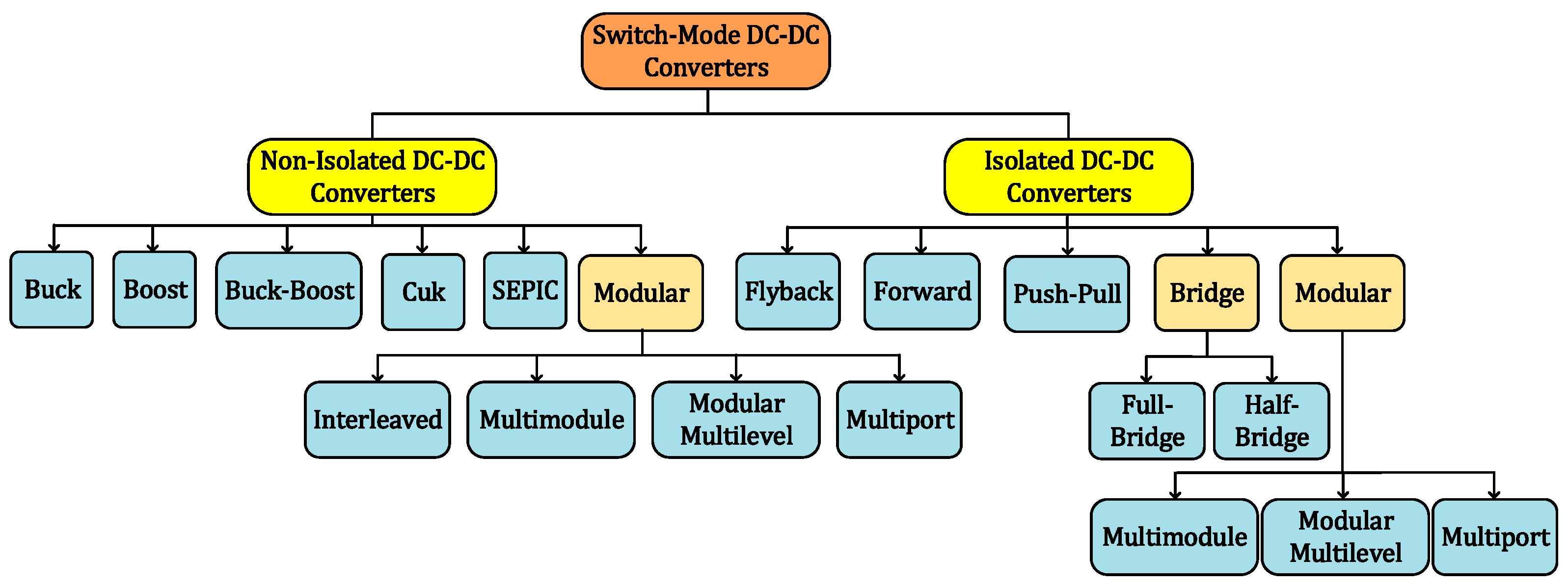
2. Basic Isolated and Non-Isolated DC-DC Converter Topologies

Converter topologies, in general, are divided into two main categories: non-isolated and isolated topologies. Figure 4 shows DC-DC converters based on isolated and non-isolated topologies. The main difference is that electrical isolation is provided between the input and the output via an intermediate transformer of medium/high frequency [18].
This survey will not focus on non-isolated DC-DC converters in Figure 4 since these converters are primarily employed in low-power applications, where galvanic isolation is not a primary requirement. Galvanic isolation in medium voltage applications is necessary to offer better switching utilization and reduce the reactive power circulation, especially when the DC link voltages input and output are not equal. The absence of an isolating transformer would result in high losses due to the excessive reactive power circulation.
As shown in Figure 4, non-isolated topologies include the DC-DC converter’s basic types: Buck, Boost, Buck-Boost, and Cuk converters. From the basic non-isolated DC-DC converters, the conventional isolated DC-DC converters in Figure 4 are derived. The isolated converters listed in Figure 4 cover wide power ranges. Modular converters will be further classified based on the number of conversion stages focusing on MV DC-DC converters.
Isolated topology can be categorized as single-ended or double-ended. An isolated converter is considered a single-ended converter if the flux during operation swings in one quadrant of the BH curve. However, it is considered as a double-ended converter if the flux during operation swings in two quadrants of the BH curve. The merits of double-ended topology over the single-ended topology are that it requires a smaller core and does not require an extra reset winding. In this section, the basic isolated DC-DC converters shown in Figure 4 are compared in terms of the output power range, cost, number of active switches, and electrical stress. The order from low-power to high-power of the basic isolated DC-DC converters is Flyback, Forward, Push-Pull, Half-Bridge (HB), and Full-Bridge (FB) [18]. All the semiconductor devices used in the figures are IGBTs. However, the power switches could also be MOSFETs. The selection of the power switches will be according to the overall system requirements. In [19], a hybrid multimodule DC-DC converter is presented where a comparison between multimodule DC-DC converter using IGBTs and MOSFETs are compared in terms of efficiency, switching frequency, power density, and volume. In [19], the hybrid concept is achieved through employing two different groups of multimodule converters. The first is designed to be in charge of a high fraction of the total required power, operating at a relatively low switching frequency. The second is designed for a small fraction of the total power, operating at a relatively high switching frequency. To support the power converter controller design, a generalized small-signal model for the hybrid converter is studied. Additionally, cross feedback output current sharing (CFOCS) control for the hybrid input-series output-parallel (ISOP) converters is examined to ensure uniform power-sharing and the desired fraction of power handled by each multimodule group. The power loss analysis of the hybrid converter is provided and compared to conventional multimodule DC-DC converters.
The flyback converter shown in Figure 5a is usually employed in low-power applications. It is a low-cost converter and easy to use since it involves only one active switch. However, the Flyback converter is a single-ended converter and requires additional capacitors because of the high ripple currents at the input and the output sides. Accordingly, this converter suffers from poor transformer utilization. Forward and Active Clamp Forward converters are usually used in medium power applications. These two converters also suffer from the poor utilization of the transformer since they are classified as single-ended topologies, in addition to the limited duty cycle in both converters.
The other three topologies are Push-Pull, HB, and FB, shown in Figure 5c–e, respectively, and are double-ended topologies that can be employed in high-power applications since full utilization of the transformer can be achieved [18]. In addition, further optimization of the transformer can be achieved because of the large duty cycle range. To clarify, a duty cycle of 50% per side can be achieved in double-ended topologies, which corresponds to an effective duty cycle close to 100% at the filter inductor of the output. Accordingly, operating at an effective duty cycle of 100% will significantly reduce the output filter size and the transformer RMS current.
Even though the push-pull converter is a double-ended topology, during the off state, the maximum voltage stress across the switching devices of the primary side reaches above two times the supply voltage. This issue is avoided in the HB topology, where the primary voltage stress does not increase beyond the supply voltage. In addition, an HB converter allows for better transformer utilization since it has one primary winding. The FB converter has double-ended merits. In addition, the switch voltage at the primary side does not exceed the supply voltage. Similarly, it has a single primary winding, which allows for good transformer utilization. However, in terms of complexity and cost, the FB converter is more complex and is of higher cost when compared to the HB converter due to the employment of four switches at the primary side [18]. Table 1 presents a comparison between the isolated DC-DC topologies in terms of the power range, transformer utilization, number of active switches and cost.
This section focused on the conventional DC-DC topologies used in modular structured DC-DC converters to meet higher voltage and power requirements. The following section will review the modular DC-DC converters classified based on the conversion stages, where any of the discussed topologies in this section can be employed.

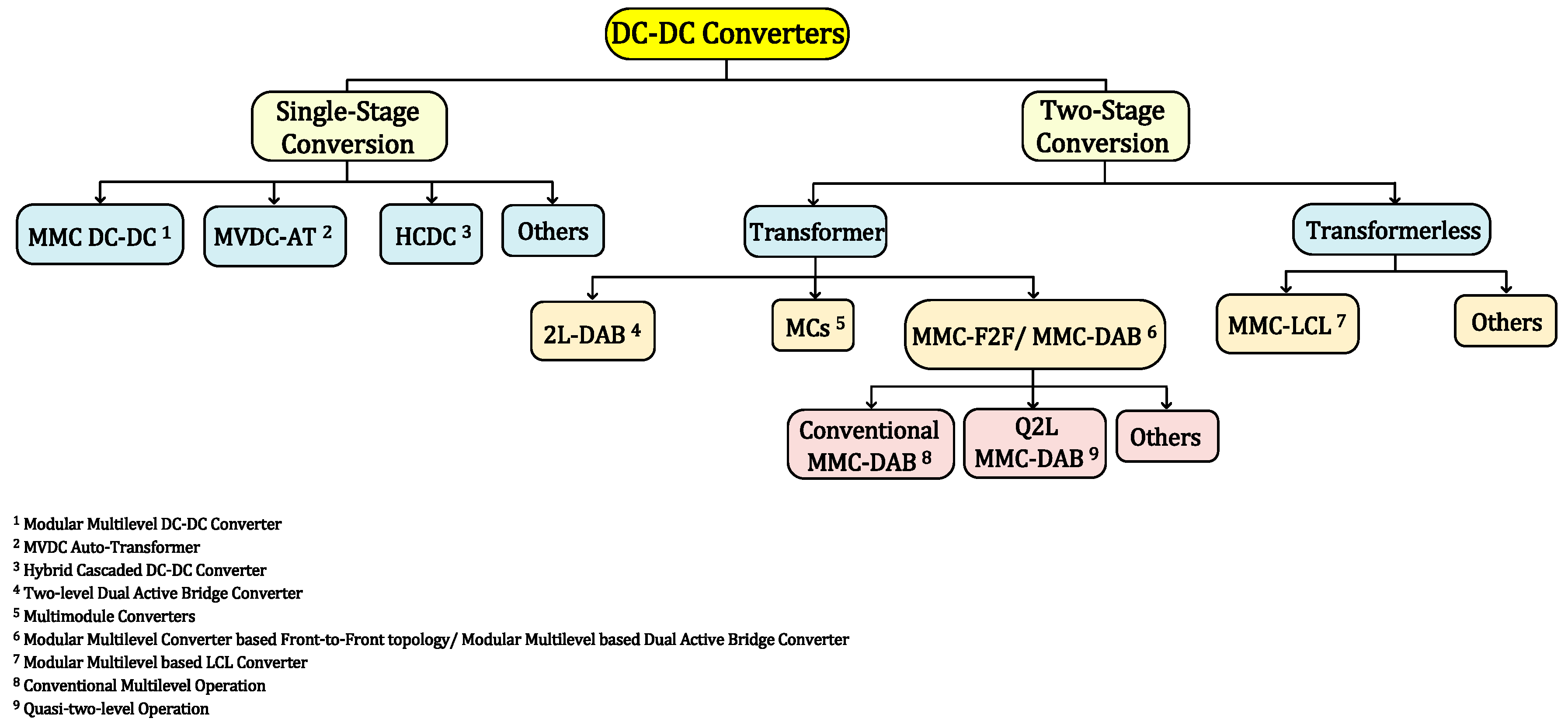
3. DC-DC Converters for Medium Voltage E-Bus Charging

Two different methods can be established to meet different voltage and power requirements. The first method is established by utilizing power switches in two-level DC-DC converters with high voltage and high current ratings to be connected in series and/or parallel. Nevertheless, unsymmetrical voltage sharing would result from the series connection of the semiconductor devices due to the parameters mismatch. This mismatch includes leakage inductance, switching delays, and collector-to-emitter capacitance. Consequently, to avoid the unsymmetrical sharing, voltage balancing techniques are essential to avoid any failure since the failure in one element will lead to the entire converter failure, resulting in low reliability [20]. However, in the second method, the modular concept is established in the power converters [21]. In other words, MV E-bus charging technologies have motivated the use of modular converter systems. Modular converters are considered a cost-effective alternative. In addition, if any failure cases occur, low-power modules can be hot-swapped, facilitating the maintenance of such converters. Moreover, to meet higher power requirements, the number of the employed modules can be scaled up. Furthermore, redundancy can be established through employing more modules [22]. To clarify, each unit is responsible for delivering a fraction of the total input power in modular structure-based DC-DC converters. Accordingly, the installed semiconductor devices are of low voltage and current ratings in which operating at high switching frequency can be achieved, improving the converter system’s efficiency, lowering the losses, and reducing the transformer size. To avoid the drawbacks associated with the series connection in the first approach, modular converters topologies such as Multimodule Converters (MCs) and Modular Multilevel Converters (MMCs) are used to provide modularity features and achieve the required voltage and power levels. These two converters will be further discussed in the following sections in MV power grids for E-bus charging.
One of the possible DC-DC converters classifications is based on the number of conversion stages. The first category is a single-stage conversion with no distinct intermediate AC link. While the second category is the two-stage conversion, where there is an intermediate AC link between two AC-DC converters [23]. In single-stage conversion, one converter is used, resulting in a lower number of switches when compared to two-stage conversion and accordingly lower weight, volume, and cost. Figure 6 shows the classification of the DC-DC converters based on the conversion stages, where the two-stage conversion can be further classified based on the AC link between the two DC-AC converters. The first configuration is with a transformer; however, the second configuration is transformerless. The AC link waveforms can have the sinusoidal, squared, or trapezoidal form [23].
The following subsections will cover some of the DC-DC converters that are proposed in literature applicable to MV E-bus fast charging applications, focusing on modular DC-DC converters. Each type will be discussed, highlighting the merits and demerits of each converter. In addition, a comparison between the DC-DC converters listed in Figure 6 will be carried out.

3.1. Single-Stage DC-DC Converters

The following subsections present some of the single-stage DC-DC converters proposed in the literature applicable for MV E-bus fast-charging applications.

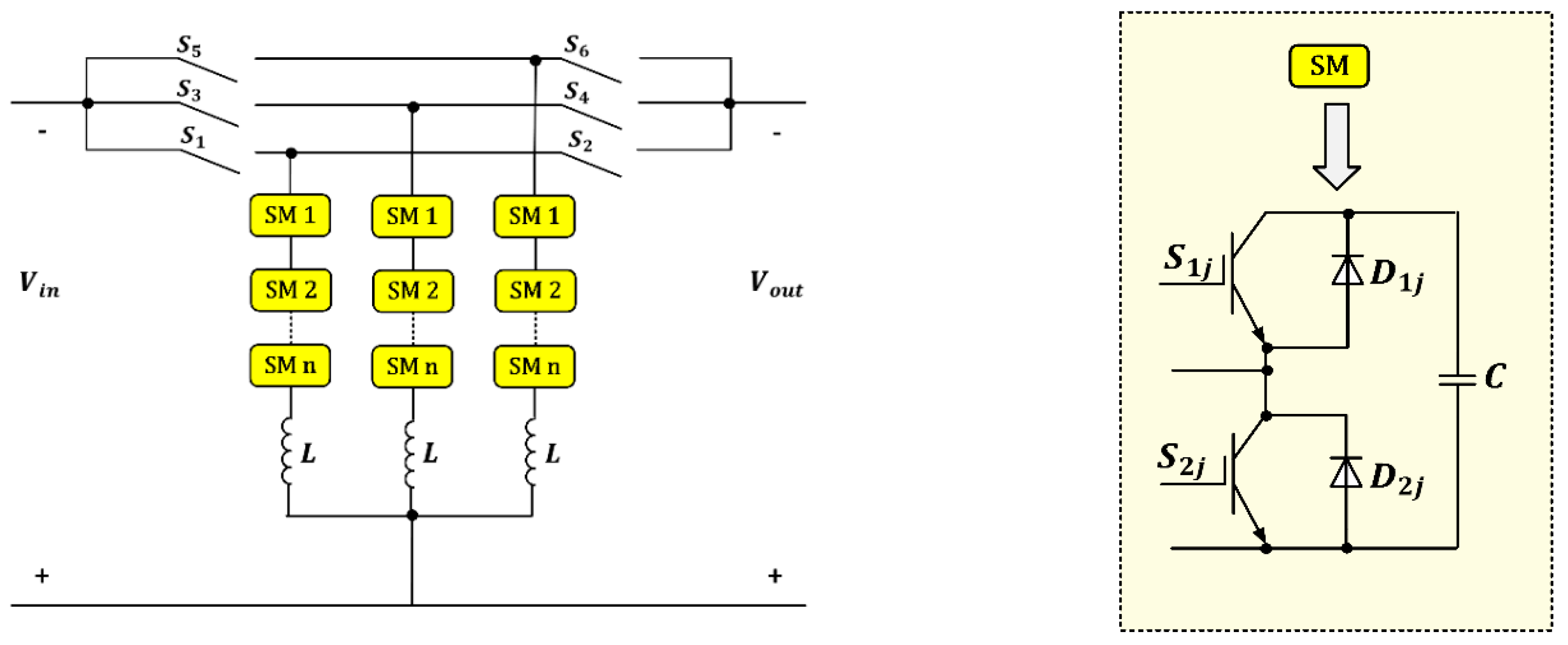
3.1.1. Modular Multilevel DC-DC Converter (MMC)

The first representation of the single-stage conversion is the MMC provided in [24] and shown in Figure 7. A secondary power loop is introduced to exchange power with the primary power loops in this topology. By using the orthogonal power flow principle at different frequencies, the power between the primary and secondary loops is exchanged. This topology requires large filter components, making it not promising for DC-DC conversion [23,24].
In [21], the MMC DC-DC converter shown in Figure 7 has been compared to the DAB DC-DC converter in four different scenarios. According to the study carried out in [21], the MMC DC-DC converter investment costs are at least three times higher than the investment costs of the converter system based on DAB. This is due to the fact that MMC DC-DC converter requires more semiconductor devices. It is concluded from [21] that the MMC DC-DC converter is not applicable to high-voltage ratios because of the poor efficiency resulting from the high circulating current in the converter. In addition, the number of semiconductor devices will be much higher. However, if the voltage ratio between the primary and secondary voltages is not high and galvanic isolation is not a requirement, then an MMC DC-DC converter will be preferable.

3.1.2. MVDC Auto-Transformer (MVDC-AT)

The MVDC Auto-Transformer (MVDC-AT) proposed in [25,26] and shown in Figure 8 is a single-stage converter that consists of two MMCs connected in series with a common AC link to allow energy transfer between the upper and the lower converters. In this topology, the installed transformer power ratings and conversion losses can be minimized since only a portion of the overall DC power has to be converted [23].
In [27], the DAB DC-DC converter is compared to the MVDC-AT shown in Figure 8. However, in [28], the MMC-based Front-to-Front (F2F) topology has been compared with the MVDC-AT, where it is found that MVDC-AT can transfer higher DC power with lower semiconductor effort. It is concluded that MVDC-AT is an effective solution when galvanic isolation is not required since the transformer used is smaller in size. However, the transformer windings are exposed to high-voltage stress. In addition, HB cells in the outer arms need to be substituted by FB cells to avoid the propagation of the DC fault [23,28].

3.1.3. Hybrid Cascaded DC-DC Converter (HCDC)

A new family of DC-DC converters classified as single-stage converters is proposed in [29]. This hybrid cascaded DC-DC converter consists of semiconductor devices and a stack of SMs [23]. To illustrate, the converter presented in [29] and shown in Figure 9 is a polyphase structure, where each phase contains a semiconductor device and an energy storage device. In this converter, more than one phase is used to avoid the interruption of power flow. The controlled switch contains IGBTs connected in series, where each arm has two switches. However, the storage device is created through cascading HB-SMs [23]. The main advantage of this converter is that it can operate under soft-switching since the SMs are highly controllable. Despite the low switching losses achieved, this converter suffers from the high conduction losses because of the high number of semiconductors used in the conduction path [23,29]. In addition, to meet higher voltage and higher power demands, hundreds of IGBTs are connected in series, making the voltage balance across the IGBTs an issue. Other DC-DC converters classified as single-stage converters can be found in [23,30,31,32].

3.2. Two-Stage DC-DC Converters

Two AC-DC converters are connected to F2F via an intermediate AC link [23]. This concept was initially introduced through the DAB in [33,34]. This category can be further classified according to the AC link. The possible configurations are using a transformer or transformerless configuration; through using L filter or LCL filter [23].
Transformerless topologies can be used with low transformation ratios; however, it is essential to use the transformer topologies in medium and higher ratios. The main advantage of using an L filter is avoiding using the bulky AC transformer. However, no isolation is provided to prevent the fault from propagating to other DC systems. A transformerless topology, namely the MMC-based LCL DC-DC converter and other DC-DC converters containing AC transformers, are presented in the following subsections.

3.2.1. MMC-Based LCL DC-DC Converter

Generally, LCL DC-DC topology provides high stepping ratios and inherent DC fault isolation without the need for an AC transformer [23,35]. Due to the absence of the AC transformer in LCL topology, the operating frequency can be increased. To provide a modular structure, lower power losses, higher power quality, and higher reliability, the MMC converter is introduced in resonant topologies, as shown in Figure 10 [23,35]. In addition, the MMC with the resonant topologies assists in having a higher efficiency for all transformation ratios [23]. Other transformerless topologies are presented in [23,36,37].

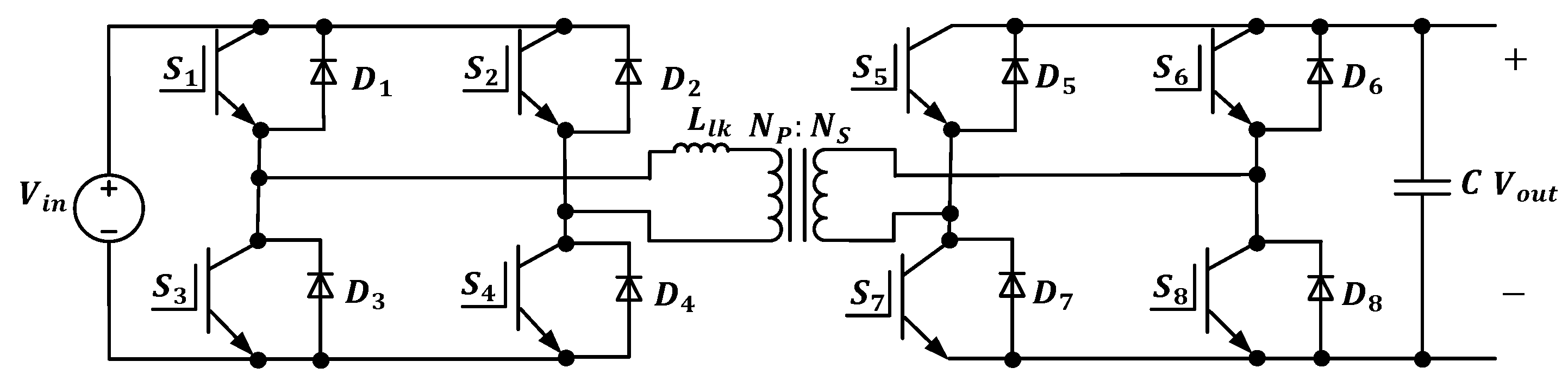
3.2.2. Two-Level Dual Active Bridge Converter (2L-DAB)

The DAB DC-DC converter is a topology used in high-power applications [38,39]. Figure 11 presents the DAB configuration, which involves two active bridges connected through an intermediate high-frequency transformer. The first FB converts the input side DC voltage to a high-frequency AC voltage; however, the second FB converts back the square wave AC voltage to a DC output voltage [40].
The DAB can be a single-phase converter or three-phase converter depending on the design criteria [17]. The maximum power transferred depends on the leakage inductance of the intermediate transformer, which acts as an energy transferring element [33]. The DAB topology provides bidirectional power flow. This is done by controlling the phase shift between the primary and secondary bridge [20]. The switches can be switched at ZVS and/or Zero Current Switching (ZCS). To further illustrate, during the switching actions, the transformer leakage inductance resonates with switching devices’ output capacitances to limit the rate of change of voltage and current across the semiconductor devices [18]. This action reduces the switching loses of the converter and increases the power efficiency.
Several control strategies are presented in order to increase the soft-switching range and reduce the transformer current. In addition, a high conversion ratio can be obtained by choosing the transformer turns ratio. However, the active bridges should be rated at the full converter power and voltage, limiting their employment in high-power applications since the semiconductor switches should be connected in series and/or parallel to meet the voltage and/or current requirements. In addition, high isolation is required at higher voltage levels for the intermediate transformer. Moreover, one of the two-level DAB converter design challenges is that at higher operating voltages, the rate of change of voltage across the intermediate transformer is high [17].
In order to avoid these problems and be able to employ a DAB converter in high-voltage high-power applications, multiple DAB converter units can be connected in series and/or parallel to increase the voltage and current ratings as proposed in [41,42,43]. This is termed a multimodule DC-DC converter, which will be further discussed in the following subsection.
Applying the modular concept to the two-level DAB would achieve easier scalability. In addition, installing additional modules makes the system more reliable. However, connecting multiple DAB units in series/parallel will require special attention to the isolation level of the low-power transformers, which results in higher costs [17]. There are four possible architectures for modular two-level DAB, which are: Input-Series Output-Series (ISOS), Input-Series Output-Parallel (ISOP), Input-Parallel Output-Parallel (IPOP), Input-Parallel Output-Series (IPOS) [44]. Figure 12 presents the four modular DAB architectures considering three DAB units.

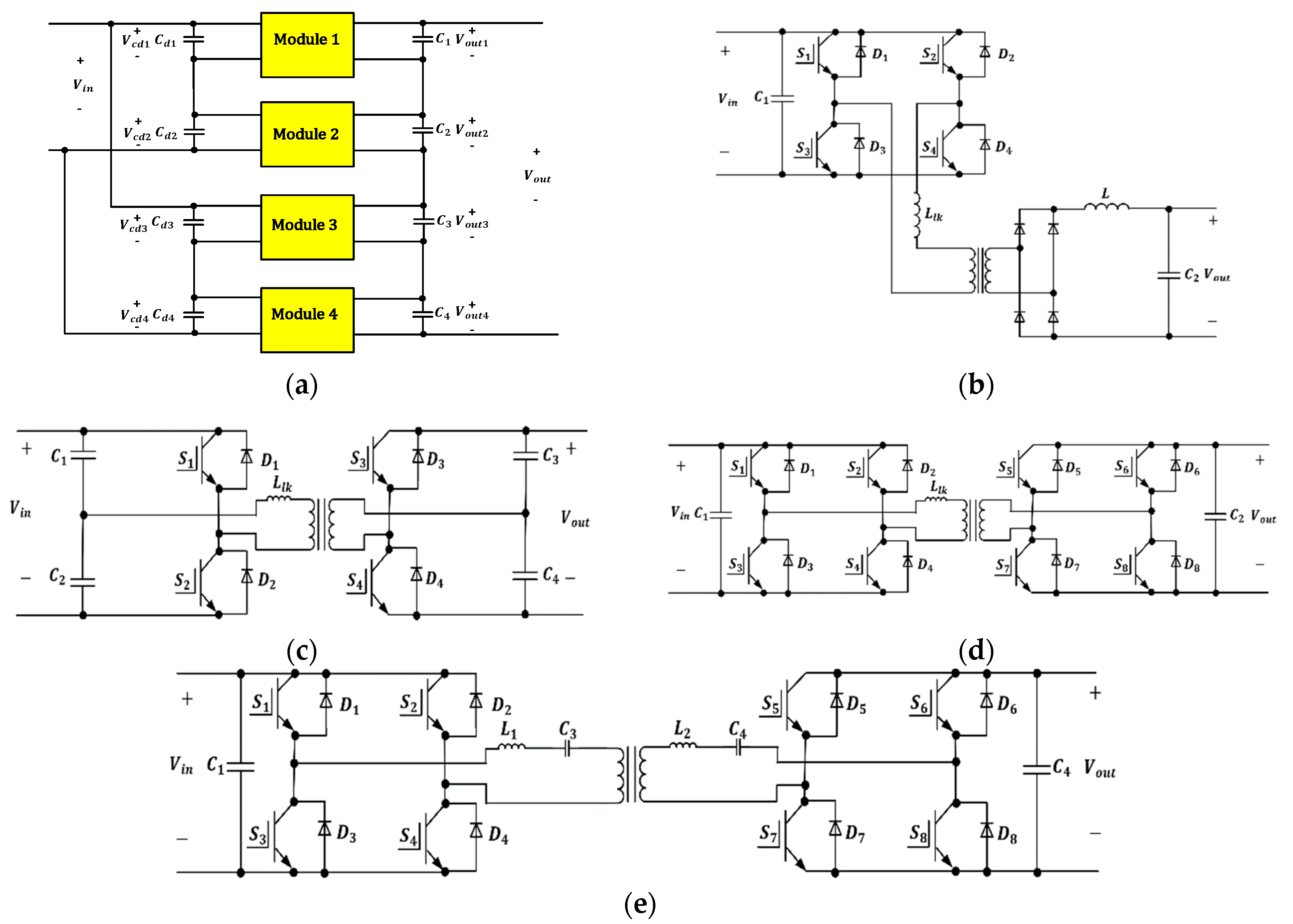
3.2.3. Multimodule DC-DC Converters (MCs)

The multimodule DC-DC converter shown in Figure 13a can be employed in medium/ high-voltage high-power applications. In this converter, each SM contributes a small portion of the total power. Therefore, high switching frequency operation can be achieved in multimodule DC-DC converters without affecting the efficiency of the converter system [45].
Multimodule DC-DC converters can offer both unidirectional and bidirectional power flow. In such a configuration, power-sharing control techniques are required to ensure equal power distribution [45]. However, the converter shown in Figure 13b based on FB topology faces some drawbacks that can be summarized as high reverse recovery currents in high-power applications. In addition, the soft-switching technique in the FB converter can only be achieved within a limited range [33,34,45]. Although, several solutions have been suggested in [33,34,46,47] to reduce the high reverse recovery current.
Figure 13a presents a generic multimodule DC-DC converter, where any of the configurations shown in Figure 13b–e can be used. In Figure 13e, the frequency of the FB converters is adjusted based on the AC link resonant frequency to provide a sinusoidal voltage waveform across the transformer’s windings, enabling the power switches to operate near the ZCS. However, in this approach, the series resonant capacitor voltage is high, which oversizes the SM’s resonant capacitor. Accordingly, the resonant version is not preferable compared to the non-resonant version in Figure 13c, which provides a smaller size and lighter weight. Generally, most resonant converters have high-voltage or high-current stresses on the switching devices. This can be accepted in low/ medium voltage applications but cannot be tolerated in high-voltage applications. Resonant versions are single-phase converters that suffer from large ripple currents on both DC links.
The main drawback accompanied with the multimodule DC-DC converters discussed in this section is that when employed in voltage levels that are beyond the medium-voltage, high isolation level will be required with the multiple transformers used [45]. However, in multimodule DC-DC converters, an AC transformer offering galvanic isolation is essential to offer series/parallel connections at the input and output sides. Several research studies have addressed the concept of multimodule DC-DC converters. In [48], a generalized modeling and control approach for modular isolated DC-DC converters for ultra-fast EV chargers is presented. In [49], an ISOP modular DC-DC converter for low-speed EVs is presented. In [19], hybrid multimodule DC-DC converters for ultrafast EV chargers are presented.
Summarizing the concept of multimodule DC-DC converters, this topology is a modular structure-based converter. It can offer a bidirectional power flow by using SMs containing DAB, DHB, and series resonant converters, where each topology has its merits and demerits [23,50]. Soft switching operation, along with higher switching frequency, can be achieved in multimodule DC-DC converters, resulting in significantly reducing the component volume without sacrificing efficiency [23]. In multimodule DC-DC converters, the modularity concept is applied to the entire stage and not only in the power electronics stage. In addition, a higher switching frequency in the AC link can be achieved, which results in weight and size reduction.

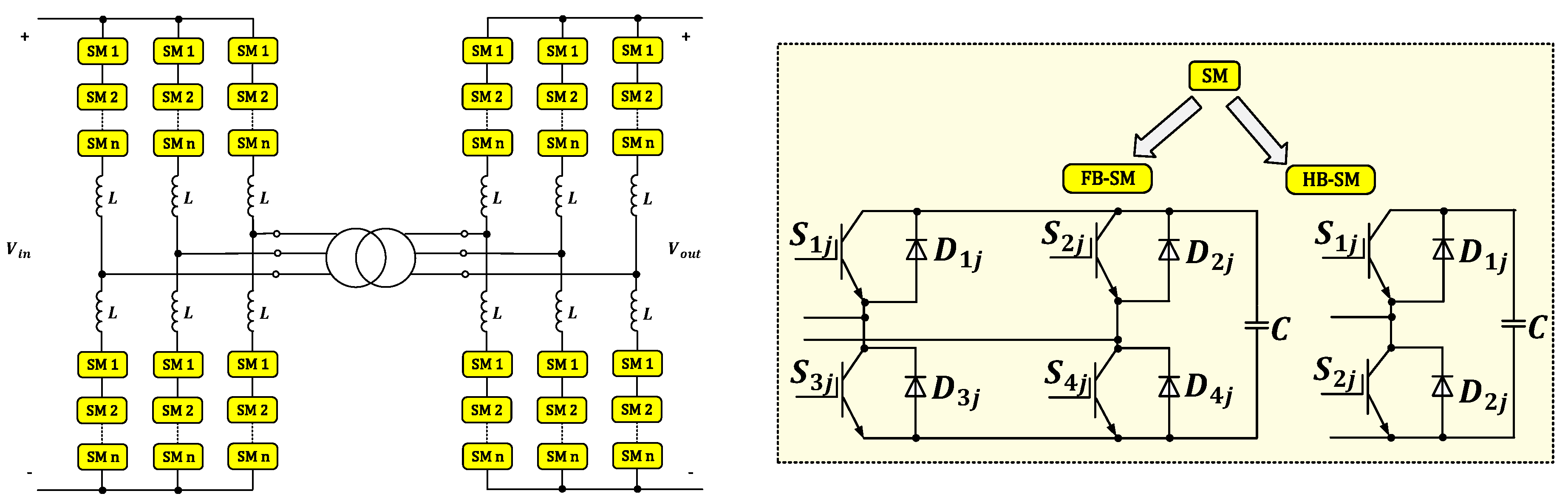
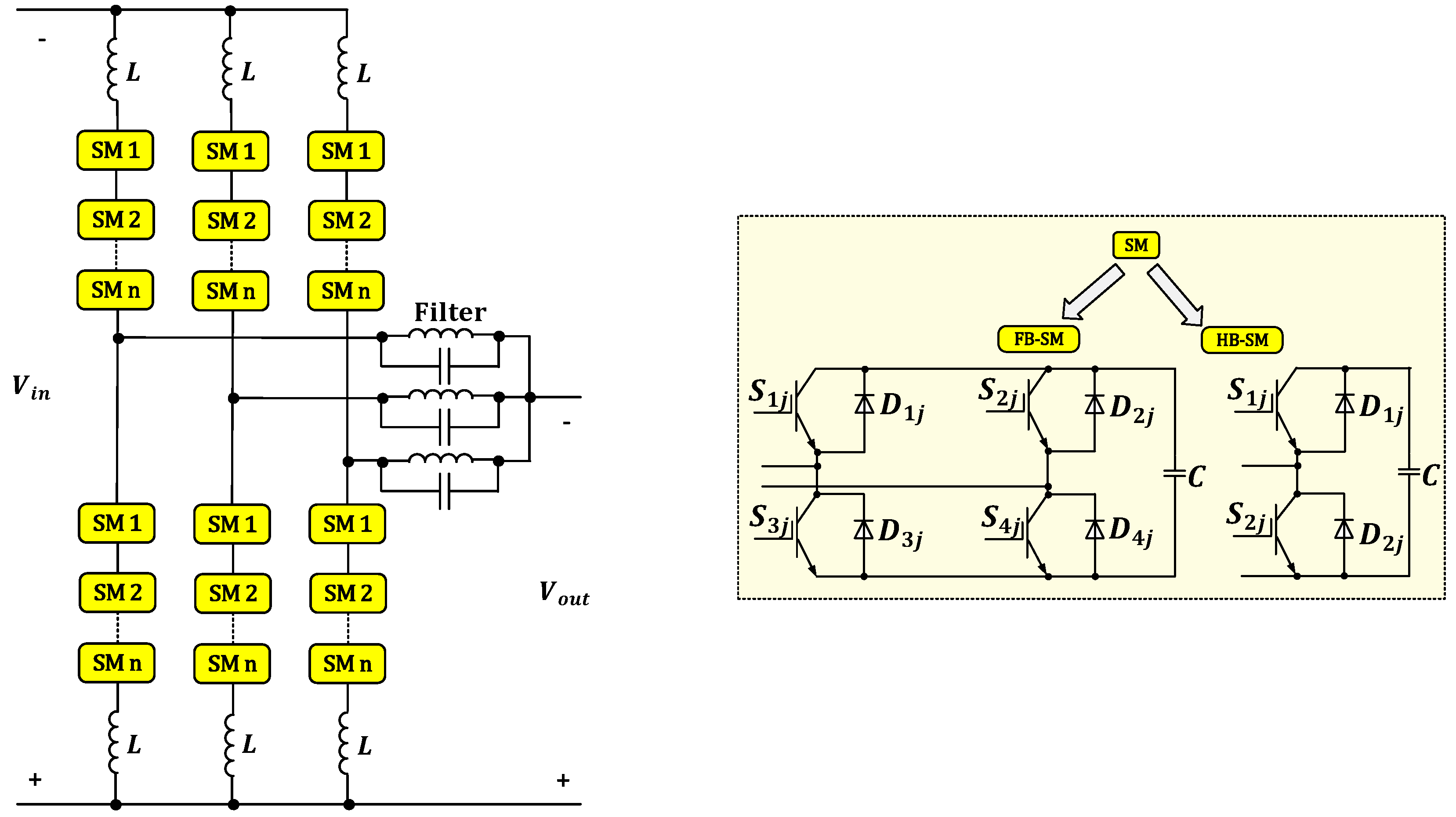
3.2.4. Modular Multilevel Converter (MMC-DAB/ MMC-F2F)

In 2003, Lesnicar and Marquardt introduced the DC-AC MMC concept, where several HB-SMs of low-voltage rating are switched to produce a multilevel AC voltage waveform [17,21,51]. The idea of replacing the conventional DAB switches with low-voltage SMs has gained popularity [52,53]. The DAB converter based on the MMC concept shown in Figure 14 is a F2F topology that does not need multiple low-power transformers as the series and/or parallel DAB converters. Instead, a multilevel or two-level voltage waveform is generated across the winding of the transformer. The MMC-based F2F topology is considered one of the promising DC-DC converters used in MV E-bus fast charging. As shown in Figure 14, the MMC-F2F converter consists of two full-scale converters connected via an intermediate transformer. The first converter converts from DC to AC, the second converts from AC to DC, and the intermediate transformer provides galvanic isolation and changes the voltage level if needed. The MMC-based DAB topology will provide easy power rating adoption and fault blocking capability. In this topology, the semiconductor switches series connection is also avoided. However, the total installed SMs ratings are poorly utilized due to the usage of two fully rated DC-AC stages, resulting in high cost, size, and power losses [17,54].
The MMC-based F2F topology is considered one of the promising DC-DC converters used in MV E-bus fast charging. As shown in Figure 14, the MMC-F2F converter consists of two full-scale converters connected via an intermediate transformer. The first converter converts from DC to AC, the second converts from AC to DC, and the intermediate transformer provides galvanic isolation and changes the voltage level if needed.
To address the technical challenges and control of the MMC-F2F topology, extensive research efforts have been made. The prominent features of MMC-F2F topology can be summarized as follows [17]:
  • The use of multiple low-voltage SMs enabled the converter to be fully modular and scalable, where connecting SMs in series can achieve different voltage and power levels.
  • In addition, the multilevel architecture allowed for low total harmonic distortion in the AC waveform output, which will significantly reduce the AC side filtering requirement.
  • Low electromagnetic interference is achieved because of the low rate of change of voltage and the enhanced reliability introduced by the redundant SMs.
The use of medium frequency in the MMC-DAB converter offers a compact transformer design and reduces the total size of the passive elements. In MMC-DAB, the AC link can be operated in two modes. The first mode uses full multilevel modulation with sinusoidal voltage [45]. However, the second mode is the Quasi-two-level (Q2L) mode with trapezoidal voltage as suggested in [55]. The operation of both modes is explained in [45].
A.
Conventional Multilevel operation of MMC-DAB
The main features of the first mode can be summarized in low voltage stresses on the MMC-DAB transformer and low switching losses compared with the 2L-DAB. This is accomplished through the small voltage step sequential switching [45]. In addition, MMC-DAB operating in the first mode has a lower power density than the 2L-DAB since the active power with the low order voltages and current harmonics is not fully utilized [21,45,56,57]. Moreover, soft switching for all the switching devices cannot be achieved as in the DAB configuration. Accordingly, the cell capacitance must be oversized to avoid high-voltage stresses across the switching devices [45].
B.
Quasi-two-level (Q2L) operation of MMC-DAB
The second mode, which is the Q2L operation of MMC, is proposed in [57]. In this mode, the MMC operates as a two-level converter, where the modular converter cell capacitors are used as a clamping network to ease the output phase voltage transitions. In other words, the converter generates a square wave with a controllable change in the rate of the voltage level through the cell voltages employment to create transient voltage levels. This would diminish the cell capacitance energy storage requirement and the MMC overall footprint, making the Q2L MMC-DAB a suitable and promising solution for MV E-bus charging applications [45,57]. Accordingly, employing Q2L MMC-DAB in such applications would result in high efficiency, low switching frequency, and system reliability.
To further illustrate, the DC transformer based on MMC proposed in [57] consists of two three-phase MMCs connected via AC transformer, where HB cells are employed in both MMCs. This mode offers a considerable reduction in the converter’s cost, weight, and footprint [23,57]. The DC voltage regulation is managed by controlling the phase shift and the voltage magnitude. In order to mitigate the voltage stress on the AC transformer stage, both converters operate in a Q2L mode, which would make the topology applicable for medium voltage and high voltage levels. Similar to the first staircase mode operating with a sinusoidal waveform, the trapezoidal voltage waveform is created through the cell’s sequential switching. The cell capacitors are used as energy tanks to produce intermediate voltage levels for a few microseconds during the transitions. This would significantly diminish the cell capacitance.
The purpose of the presented Q2L operating mode for MMC in [57] is to be utilized as a DAB DC transformer topology. In this mode, several merits are offered, which can be highlighted in the two-level operation with controlled values for the rate of change of voltage, in addition to the significant reduction in the converter footprint due to the low cell capacitance requirement. Moreover, soft switching can be achieved using the DC transformer topology. Furthermore, this mode offers flexibility in installation and manufacturing.
Up to this point, the basic DC-DC converter topologies are discussed. However, more recent concepts substitute the DC-AC converters in the F2F topology with new hybrid concepts. These DC-AC converters are based on F2F topology and combine the desired features of the MMC and the two-level converter. These presented converters include Hybrid Cascaded Two-level converter, Alternative Arm MMC (AA-MMC), Controlled Transition Bridge (CTB), and Transmission Arm Multilevel Converter (TAC) operating in Q2L that are presented in [23,45,58].
C.
MMC Topologies Assessment
In [59], the F2F converter, MVDC-AT, and MMC DC-DC converter are compared in terms of their functionality, efficiency, and topology effort.
The comparison carried out in [21] and [27] between the MMC DC-DC and DAB DC-DC converters and between DAB and MVDC-AT converters is based on different case studies. However, in [59], a generalized approach is used to compare the three MMC converter-based topologies regardless of the actual voltage or the desired power levels.
The three MMC topologies have been compared by noticing their performance characteristics: switching power utilization, conversion efficiency, and passive component efforts. Despite the absence of galvanic isolation, it has been shown in [59] that the MVDC-AT provides high efficiency and uses small passive components compared to other topologies. Accordingly, MVDC-AT is preferred economically when galvanic isolation is not a requirement. This topology is also considered the most suitable solution for low and medium transformation ratios.
A comparison between the three MMC topologies and the 2L-DAB and the MC-DAB-based DC-DC converters is presented in Table 2. The converters are compared in terms of the number of conversion stages, galvanic isolation, transformation ratio, semiconductor efforts, switching frequency, and transformer size.

4. Medium-Voltage DC-DC Converters Challenges and Requirements

The use of high-frequency is an attractive solution for obtaining magnetic components with reduced volume and weight. However, switching at high frequencies will lead to an extremely high rate of change of voltage, making the transformer’s design more challenging. In other words, the transformer design will be difficult in terms of isolation and difficulty in transmitting power with dominant low-order harmonics [45]. The safety galvanic isolation standards by IEC are provided in [59,60].
Talking about the most desirable features of DC-DC converters, Medium-voltage DC-DC converters should be scalable to achieve the required voltage and power ratings. In addition, an interfacing transformer for galvanic isolation is likely to be used [34,45].
Furthermore, voltage stresses at the interfacing transformer primary and secondary windings, as well as the voltage stresses across the switching devices of the converter and the passive components, must be controlled. Moreover, constraints should be imposed on the AC link fundamental frequency since the interfacing transformer weight and volume reduction in the high-voltage DC-DC converter are constrained by the switching losses level. However, higher AC link frequency can be achieved in multimodule DC-DC converters since each SM is rated at low voltage and power levels.
Regarding the system-level challenges, power quality issues in DC distribution and microgrids should be considered. Power quality in DC systems is mainly concerned with the employed power conversion stages, considered the main building blocks in DC systems. In DC distribution, the four fundamental power quality concerns are identified as: harmonic currents, inrush current, fault current, and grounding [61,62,63].
  • Harmonic Currents: The existence of voltage and current oscillations in such systems makes the harmonics discussion relevant in which the term harmonics refers to the oscillatory voltages and currents. Due to the non-linear effects of power converters, harmonic currents, and circulating currents result. To limit the harmonic currents, filters are required. Voltage oscillations and resonance currents can result from harmonic currents, which may reflect voltage harmonic distortion at the point of common coupling (PCC) of the AC grid. In this regard, utility customers are limited by the harmonic current requirements in international standards (e.g., IEEE 519) [64].
  • Inrush current: To control the harmonic currents and voltage ripple resulting from the load and the source converter, respectively, filters are utilized in which the filter capacitance may cause inrush currents. To solve the inrush current problem, soft-start techniques are addressed in [65].
  • Fault Current: Due to the absence of periodic voltage and zero current crossings, arcing faults cannot be detected and extinguished easily in DC systems. Additionally, fault current contribution represents an issue in DC networks. Therefore, a DC-DC converter with fault current blocking capability is required. In this regard, protection in DC systems is of high interest. A review focusing on DC protection is carried out and conducted in [66].
  • Grounding: The selection of the grounding configuration in the DC systems affects the power quality as well as the safety of the overall system, especially in fault conditions. In this regard, the European Telecommunications Standards Institute (ETSI) published a standard document that provides details about grounding techniques for data centers [67].
In [68], an overview of DC system architectures is discussed. In which safety and protection concerns in DC distribution systems are discussed in terms of personal and equipment protection as well as grounding methods.
Transportation systems are considered sources of electric and magnetic fields to which a large portion of the population is unavoidably exposed. Accordingly, investigation of such effects with the long-term exposure of the public to the low-frequency electromagnetic field (EMF) is crucial. In [69] and [70], EMF exposure level measurements are performed and analyzed under different scenarios. From the study performed in [69], distributing passengers in a uniform manner is highly recommended to reduce the effects of undesired exposure. The simulation methodology provided in [69] can be used to assess the limitations and recommendations for EMF exposure.

5. Conclusions

In this paper, the basic isolated DC-DC converters are discussed and compared in terms of their power range, transformer utilization, number of active switches, and cost. In addition, isolated DC-DC converters are categorized and presented as single-ended and double-ended topologies. Moreover, DC-DC converter topologies applicable for MV E-bus fast charging applications are classified according to the number of conversion stages: single-stage or two-stage conversions. These converters include DAB modular-based structure converter, and MMC-based DAB are discussed where the merits and demerits of each topology are highlighted. Furthermore, this review illustrates how DAB converters are employed in different power level applications through the series and/or parallel connection of multiple DABs or through the MMC-based DAB structure. Furthermore, the challenges and required features for MV DC-DC converter topologies are discussed.

Author Contributions

Conceptualization, M.E. and A.M.; methodology, M.E.; investigation, M.E. and A.M.; resources, M.E. and A.M.; data curation, M.E. and A.M.; writing—original draft preparation, M.E.; writing—review and editing, M.E. and A.M.; visualization, A.M.; supervision, A.M.; project administration, A.M.; funding acquisition, A.M. All authors have read and agreed to the published version of the manuscript.

Funding

This work was supported by NPRP grant NPRP (10-0130-170286) from the Qatar National Research Fund (a member of Qatar Foundation).

Institutional Review Board Statement

Not applicable.

Informed Consent Statement

Not applicable.

Data Availability Statement

Not applicable.

Acknowledgments

This work was supported in part by the National Priorities Research Program (NPRP) through the Qatar National Research Fund under Grant 10-0130-170286. Qatar National Library funded the publication of this article. The statements made herein are solely the responsibility of the authors.

Conflicts of Interest

The authors declare no conflict of interest.

References

  1. Electric Buses and Charging Infrastructures in the World-Ies-Synergy. IES. 5 March 2021. Available online: https://www.ies-synergy.com/en/electric-buses-where-are-we/ (accessed on 1 January 2022).
  2. Paddon, T.; Welch, D.; Silver, F. California Transit Agencies Chart a Course to Zero Emissions: A Review of Proposed Zeb Pathways under the Innovative Clean Transit Regulation; Calstart: Pasadena, CA, USA, 2021; Report; pp. 1–18. [Google Scholar]
  3. Staff, E. A Third of European Public Transport Buses to Be Zero Emission by 2030, with over 10,000 ZE Registrations Yearly beyond 2025. Sustainable Bus. 15 December 2021. Available online: https://www.sustainable-bus.com/news/electric-bus-market-ing-europe-forecast/ (accessed on 1 January 2022).
  4. Lucintel. Opportunities and Competitive Analysis of the Electric BUS Market; Lucintel: Dallas, TX, USA, 2021; Report. [Google Scholar]
  5. Mathieu, L. Electric-Buses Arrive on Time Marketplace, Economic, Technology, Environmental and Policy Perspectives for Fully Electric Buses in the EU; Transport and Environment: Brussels, Belgium, 2018. [Google Scholar]
  6. Electric Bus Market Research Report: By Vehicle (Battery Electric Bus, Plug-in Hybrid Electric Bus, Hybrid Electric Bus, Length (More than 10 m, Less than 10 m), Battery (Lithium–Iron–Phosphate, Lithium–Nickel–Manganese–Cobalt Oxide), End User (Public, Private)—Global Industry Analysis and Growth Forecast to 2026; Prescient & Strategic Intelligence: Delhi, India, 2021; Report; pp. 1–450.
  7. Jiang, M.; Zhang, Y.; Zhang, Y. Multi-Depot Electric Bus Scheduling Considering Operational Constraint and Partial Charging: A Case Study in Shenzhen, China. Sustainability 2022, 14, 255. [Google Scholar] [CrossRef]
  8. Al-Ogaili, A.S.; Al-Shetwi, A.Q.; Sudhakar Babu, T.; Hoon, Y.; Abdullah, M.A.; Alhasan, A.; Al-Sharaa, A. Electric Buses in Malaysia: Policies, Innovations, Technologies and Life Cycle Evaluations. Sustainability 2021, 13, 11577. [Google Scholar] [CrossRef]
  9. Barraza, O.; Estrada, M. Battery Electric Bus Network: Efficient Design and Cost Comparison of Different Powertrains. Sustainability 2021, 13, 4745. [Google Scholar] [CrossRef]
  10. Verbrugge, B.; Hasan, M.M.; Rasool, H.; Geury, T.; El Baghdadi, M.; Hegazy, O. Smart Integration of Electric Buses in Cities: A Technological Review. Sustainability 2021, 13, 12189. [Google Scholar] [CrossRef]
  11. Ding, X.; Zhang, W.; Wei, S.; Wang, Z. Optimization of an Energy Storage System for Electric Bus Fast-Charging Station. Energies 2021, 14, 4143. [Google Scholar] [CrossRef]
  12. Arif, S.M.; Lie, T.T.; Seet, B.C.; Ahsan, S.M.; Khan, H.A. Plug-In Electric Bus Depot Charging with PV and ESS and Their Impact on LV Feeder. Energies 2020, 13, 2139. [Google Scholar] [CrossRef]
  13. Zagrajek, K.; Paska, J.; Kłos, M.; Pawlak, K.; Marchel, P.; Bartecka, M.; Michalski, Ł.; Terlikowski, P. Impact of Electric Bus Charging on Distribution Substation and Local Grid in Warsaw. Energies 2020, 13, 1210. [Google Scholar] [CrossRef] [Green Version]
  14. Song, Z.; Liu, Y.; Gao, H.; Li, S. The Underlying Reasons behind the Development of Public Electric Buses in China: The Beijing Case. Sustainability 2020, 12, 688. [Google Scholar] [CrossRef] [Green Version]
  15. Qin, W.; Wang, L.; Liu, Y.; Xu, C. Energy Consumption Estimation of the Electric Bus Based on Grey Wolf Optimization Algorithm and Support Vector Machine Regression. Sustainability 2021, 13, 4689. [Google Scholar] [CrossRef]
  16. Li, W.; Li, Y.; Deng, H.; Bao, L. Planning of Electric Public Transport System under Battery Swap Mode. Sustainability 2018, 10, 2528. [Google Scholar] [CrossRef] [Green Version]
  17. Yang, H. Modular and Scalable DC-DC Converters for Medium-/High-Power Applications. Master’s Thesis, Georgia Institute of Technology, Atlanta, GA, USA, 2017. [Google Scholar]
  18. Wan, H. High Efficiency DC-DC Converter for EV Battery Charger Using Hybrid Resonant and PWM Technique. Master’s Thesis, Virginia Tech, Blacksburg, VA, USA, 2012. [Google Scholar]
  19. ElMenshawy, M.; Massoud, A. Hybrid multimodule DC-DC converters for Ultrafast Electric Vehicle Chargers. Energies 2020, 13, 4949. [Google Scholar] [CrossRef]
  20. Beldjajev, V. Research and Development of the New Topologies for the Isolation Stage of the Power Electronic Transformer. Master’s Thesis, Tallinn University Of Technology, Tallinn, Estonia, 2013. [Google Scholar]
  21. Engel, S.P.; Stieneker, M.; Soltau, N.; Rabiee, S.; Stagge, H.; De Doncker, R.W. Comparison of the Modular Multilevel DC Converter and the Dual-Active Bridge Converter for Power Conversion in HVDC and MVDC Grids. IEEE Trans. Power Electron. 2014, 30, 124–137. [Google Scholar] [CrossRef]
  22. Sari, H.I. DC/DC Converters for Multi-Terminal HVDC Systems Based on Modular Multilevel Converter. Master’s Thesis, Norwegian University of Science and Technology, Trondheim, Norweg, August 2016. [Google Scholar]
  23. Papadakis, C. Protection of HVDC Grids Using DC Hub. Master’s Thesis, Delft University of Technology, Delft, The Netherlands, 2017. [Google Scholar]
  24. Ferreira, J.A. The Multilevel Modular DC Converter. IEEE Trans. Power Electron. 2013, 28, 4460–4465. [Google Scholar] [CrossRef]
  25. Schön, A.; Bakran, M.M. A new HVDC-DC converter for the efficient connection of HVDC networks. In PCIM Europe Conference Proceedings; PCIM: Nürnberg, Germany, 2013. [Google Scholar]
  26. Schoen, A.; Bakran, M.M. Comparison of the most efficient DC-DC converters for power conversion in HVDC grids. In Proceedings of the PCIM Europe 2015; International Exhibition and Conference for Power Electronics, Intelligent Motion, Renewable Energy and Energy Management, Nuremberg, Germany, 19–20 May 2015; pp. 1–9. [Google Scholar]
  27. Schön, A.; Bakran, M.M. Average loss calculation and efficiency of the new HVDC auto transformer. In Proceedings of the 2014 16th European Conference on Power Electronics and Applications, Lappeenranta, Finland, 26–28 August 2014; pp. 1–10. [Google Scholar]
  28. Yang, J.; He, Z.; Pang, H.; Tang, G. The Hybrid-Cascaded DC–DC Converters Suitable for HVdc Applications. IEEE Trans. Power Electron. 2015, 30, 5358–5363. [Google Scholar] [CrossRef]
  29. Kish, G.J.; Lehn, P.W. A modular bidirectional DC power flow controller with fault blocking capability for DC networks. In Proceedings of the 2013 IEEE 14th Workshop on Control and Modeling for Power Electronics (COMPEL), Salt Lake City, UT, USA, 23–26 June 2013; pp. 1–7. [Google Scholar]
  30. Hongcheng, Y.; Cai, X. A family of un-isolated modular DC/DC converters. In Proceedings of the 2016 IEEE 8th International Power Electronics and Motion Control Conference (IPEMC-ECCE Asia), Hefei, China, 22–26 May 2016; pp. 696–702. [Google Scholar]
  31. Xing, Z.; Ruan, X.; Xie, H.; Wang, X. A modular bidirectional buck/boost dc/dc converter suitable for interconnecting HVDC grids. In Proceedings of the 2016 IEEE 8th International Power Electronics and Motion Control Conference (IPEMC-ECCE Asia), Hefei, China, 22–26 May 2016; pp. 3348–3354. [Google Scholar]
  32. De Doncker, R.W.A.A.; Divan, D.M.; Kheraluwala, M.H. A three-phase soft-switched high-power-density DC/DC converter for high-power applications. IEEE Trans. Ind. Appl. 1991, 27, 63–73. [Google Scholar] [CrossRef]
  33. Soltau, N.; Stagge, H.; De Doncker, R.W.; Apeldoorn, O. Development and demonstration of a medium-voltage high-power DC-DC converter for DC distribution systems. In Proceedings of the 2014 IEEE 5th International Symposium on Power Electronics for Distributed Generation Systems (PEDG), Galway, Ireland, 26–29 June 2014; pp. 1–8. [Google Scholar]
  34. Far, A.J.; Hajian, M.; Jovcic, D.; Audichya, Y. Optimal design of high power MMC-based LCL DC/DC converter. In Proceedings of the 2016 IEEE Power and Energy Society General Meeting (PESGM), Boston, MA, USA, 17–21 July 2016; pp. 1–5. [Google Scholar]
  35. Jovcic, D. Bidirectional, High-Power DC Transformer. IEEE Trans. Power Deliv. 2009, 24, 2276–2283. [Google Scholar] [CrossRef]
  36. Jovcic, D.; Zhang, J. High power IGBT-based DC/DC converter with DC fault tolerance. In Proceedings of the 2012 15th International Power Electronics and Motion Control Conference (EPE/PEMC), Novi Sad, Serbia, 4–6 September 2012; pp. DS3b.6-1–DS3b.6-6. [Google Scholar]
  37. Kheraluwala, M.H.; Gasgoigne, R.W.; Divan, D.M.; Bauman, E. Performance characterization of a high power dual active bridge DC/DC converter. In Proceedings of the Conference Record of the 1990 IEEE Industry Applications Society Annual Meeting, Seattle, WA, USA, 7–12 October 1990; Volume 2, pp. 1267–1273. [Google Scholar]
  38. Oggier, G.G.; GarcÍa, G.O.; Oliva, A.R. Switching Control Strategy to Minimize Dual Active Bridge Converter Losses. IEEE Trans. Power Electron. 2009, 24, 1826–1838. [Google Scholar] [CrossRef]
  39. Qin, H. Dual Active Bridge Converters in Solid State Transformers. Master’s Thesis, Missouri University of Science and Technology, Rolla, MO, USA, 2012. [Google Scholar]
  40. Chen, W. DC/DC Conversion Systems Consisting of Multiple Converter Modules: Stability, Control, and Experimental Verifications. IEEE Trans. Power Electron. 2009, 24, 1463–1474. [Google Scholar] [CrossRef]
  41. Shi, J.; Luo, J.; He, X. Common-Duty-Ratio Control of Input-Series Output-Parallel Connected Phase-shift Full-Bridge DC-DC Converter Modules. IEEE Trans. Power Electron. 2011, 26, 3318–3329. [Google Scholar] [CrossRef]
  42. Giri, R. Common-duty-ratio control of input-series connected modular DC-DC converters with active input voltage and load-current sharing. IEEE Trans. Ind. Appl. 2006, 42, 1101–1111. [Google Scholar] [CrossRef]
  43. Lian, Y.; Adam, G.P.; Holliday, D.; Finney, S.J. Medium-voltage DC/DC converter for offshore wind collection grid. IET Renew. Power Gener. 2016, 10, 651–660. [Google Scholar] [CrossRef]
  44. Adam, G.P.; Gowaid, I.A.; Finney, S.J.; Holliday, D.; Williams, B.W. Review of dc-dc converters for multi-terminal HVDC transmission networks. IET Power Electron. 2016, 9, 281–296. [Google Scholar] [CrossRef] [Green Version]
  45. Wu, H.; Lu, Y.; Mu, T.; Xing, Y. A Family of Soft-Switching DC-DC Converters Based on a Phase-Shift-Controlled Active Boost Rectifier. IEEE Trans. Power Electron. 2015, 30, 657–667. [Google Scholar] [CrossRef]
  46. Inoue, S.; Akagi, H. A bi-directional isolated DC/DC converter as a core circuit of the next-generation medium-voltage power conversion system. In Proceedings of the 2006 37th IEEE Power Electronics Specialists Conference, Jeju, Korea, 18–22 June 2006; pp. 1–7. [Google Scholar]
  47. ElMenshawy, M.; Massoud, A. Modular isolated DC-DC converters for ultra-fast EV Chargers: A generalized modeling and control approach. Energies 2020, 13, 2540. [Google Scholar] [CrossRef]
  48. ElMenshawy, M.; Massoud, A. Development of modular DC-DC converters for low-speed electric vehicles fast chargers. Alex. Eng. J. 2020, 60, 1067–1083. [Google Scholar] [CrossRef]
  49. Carrizosa, M.J.; Benchaib, A.; Alou, P.; Damm, G. DC transformer for DC/DC connection in HVDC network. In Proceedings of the 2013 15th European Conference on Power Electronics and Applications (EPE), Lille, France, 2–6 September 2013; pp. 1–10. [Google Scholar]
  50. Lesnicar, A.; Marquardt, R. An innovative modular multilevel converter topology suitable for a wide power range. In Proceedings of the 2003 IEEE Bologna Power Tech Conference Proceedings, Bologna, Italy, 23–26 June 2003; Volume 3, p. 6. [Google Scholar]
  51. Gowaid, I.A.; Adam, G.P.; Ahmed, S.; Holliday, D.; Williams, B.W. Analysis and Design of a Modular Multilevel Converter With Trapezoidal Modulation for Medium and High Voltage DC-DC Transformers. IEEE Trans. Power Electron. 2014, 30, 5439–5457. [Google Scholar] [CrossRef] [Green Version]
  52. Xing, Z.; Ruan, X.; You, H.; Yang, X.; Yao, D.; Yuan, C. Soft-Switching Operation of Isolated Modular DC/DC Converters for Application in HVDC Grids. IEEE Trans. Power Electron. 2015, 31, 2753–2766. [Google Scholar] [CrossRef]
  53. Kish, G.J.; Ranjram, M.; Lehn, P.W. A Modular Multilevel DC/DC Converter With Fault Blocking Capability for HVDC Interconnects. IEEE Trans. Power Electron. 2013, 30, 148–162. [Google Scholar] [CrossRef]
  54. Zhang, Y.; Adam, G.; Finney, S.; Williams, B. Improved pulse-width modulation and capacitor voltage-balancing strategy for a scalable hybrid cascaded multilevel converter. IET Power Electron. 2013, 6, 783–797. [Google Scholar] [CrossRef]
  55. Kenzelmann, S.; Rufer, A.; Dujic, D.; Canales, F.; de Novaes, Y.R. Isolated DC/DC Structure Based on Modular Multilevel Converter. IEEE Trans. Power Electron. 2014, 30, 89–98. [Google Scholar] [CrossRef]
  56. Gowaid, I.A.; Adam, G.P.; Massoud, A.M.; Ahmed, S.; Holliday, D.; Williams, B.W. Quasi Two-Level Operation of Modular Multilevel Converter for Use in a High-Power DC Transformer With DC Fault Isolation Capability. IEEE Trans. Power Electron. 2014, 30, 108–123. [Google Scholar] [CrossRef] [Green Version]
  57. Gowaid, I.A.; Adam, G.P.; Williams, B.W.; Massoud, A.M.; Ahmed, S. The transition arm multilevel converter—A concept for medium and high voltage DC-DC transformers. In Proceedings of the 2015 IEEE International Conference on Industrial Technology (ICIT), Seville, Spain, 17–19 March 2015; pp. 3099–3104. [Google Scholar]
  58. Schön, A.; Bakran, M.M. Comparison of modular multilevel converter based HV DC-DC-converters. In Proceedings of the 2016 18th European Conference on Power Electronics and Applications (EPE’16 ECCE Europe), Karlsruhe, Germany, 5–9 September 2016; pp. 1–10. [Google Scholar]
  59. Kusaka, K.; Orikawa, K.; Itoh, J.; Morita, K.; Hirao, K. Isolation system with wireless power transfer for multiple gate driver supplies of a medium voltage inverter. In Proceedings of the 2014 International Power Electronics Conference (IPEC-Hiroshima 2014—ECCE ASIA), Hiroshima, Japan, 18–21 May 2014; pp. 191–198. [Google Scholar]
  60. IEC 6i800-5-I; Adjustable Speed Electrical Power Drive Systems—Part 5-1: Safety Requirements—Electrical, Thermal and Energy. International Electrotechnical Commission (lEC): Genève, Switzerland, 2007.
  61. Whaite, S.; Grainger, B.; Kwasinski, A. Power Quality in DC Power Distribution Systems and Microgrids. Energies 2015, 8, 4378–4399. [Google Scholar] [CrossRef] [Green Version]
  62. Mariscotti, A. Power Quality Phenomena, Standards, and Proposed Metrics for DC Grids. Energies 2021, 14, 6453. [Google Scholar] [CrossRef]
  63. Ciornei, I.; Albu, M.; Sanduleac, M.; Hadjidemetriou, L.; Kyriakides, E. Analytical derivation of PQ indicators compatible with control strategies for DC microgrids. In Proceedings of the 2017 IEEE Manchester PowerTech, Manchester, UK, 18–22 June 2017; pp. 1–6. [Google Scholar]
  64. Blooming, T.M.; Carnovale, D.J. Application of IEEE STD 519–1992 Harmonic Limits. In Proceedings of the Conference Record of Annual on Pulp and Paper Industry Technical Conference, 2006, Appleton, WI, USA, 18–23 June 2006; pp. 1–9. [Google Scholar]
  65. Aoki, T.; Yamasaki, M.; Takeda, T.; Tanaka, T.; Harada, H.; Nakamura, K. Guidelines for power-supply systems for datacom equipment in NTT. In Proceedings of the 24th Annual International Telecommunications Energy Conference, Montréal, QC, Canada, 29 September–3 October 2002; pp. 134–139. [Google Scholar]
  66. Cuzner, R.M.; Venkataramanan, G. The Status of DC Micro-Grid Protection. In Proceedings of the 2008 IEEE Industry Applications Society Annual Meeting, Edmonton, AB, Canada, 5–9 October 2008; pp. 1–8. [Google Scholar]
  67. ETSI EN 301 605; Environmental Engineering (EE); Earthing and Bonding of 400 VDC Data and Telecom (ICT) Equipment. ETSI: Nice, France, 2011; Volume 1, pp. 1–85.
  68. Prabhala, V.A.; Baddipadiga, B.P.; Fajri, P.; Ferdowsi, M. An Overview of Direct Current Distribution System Architectures & Benefits. Energies 2018, 11, 2463. [Google Scholar]
  69. Celaya-Echarri, M. Spatial Characterization of Personal RF-EMF Exposure in Public Transportation Buses. IEEE Access 2019, 7, 33038–33054. [Google Scholar] [CrossRef]
  70. Halgamuge, N.; Abeyrathne, C.; Mendis, P. Measurement and analysis of electromagnetic fields from trams, trains and hybrid cars. Radiat. Prot. Dosim. 2010, 141, 255–268. [Google Scholar] [CrossRef] [PubMed]
Figure 1. Evolution of Electric Buses [4].
Energies 15 05487 g001
Figure 2. Global E-Bus charging infrastructure [6].
Energies 15 05487 g002
Figure 3. Block diagram for a typical charger.
Energies 15 05487 g003
Figure 4. Switch-Mode DC-DC converters classification.
Energies 15 05487 g004
Figure 5. Basic isolated DC-DC converters: (a) Flyback converter; (b) Forward converter; (c) Push-Pull converter; (d) Half-Bridge converter; (e) Full-Bridge converter.
Energies 15 05487 g005
Figure 6. DC-DC converters classification based on the number of conversion stages.
Energies 15 05487 g006
Figure 7. Modular Multilevel DC-DC converter (MMC) circuit diagram.
Energies 15 05487 g007
Figure 8. MVDC Auto-Transformer (MVDC-AT) converter circuit diagram.
Energies 15 05487 g008
Figure 9. Hybrid Cascaded DC-DC Converter (HCDC) circuit diagram.
Energies 15 05487 g009
Figure 10. MMC-LCL converter circuit diagram.
Energies 15 05487 g010
Figure 11. Dual Active Bridge (DAB) converter circuit diagram.
Energies 15 05487 g011
Figure 12. Modular DAB DC-DC converter architecture: (a) ISOS; (b) ISOP; (c) IPOP; (d) IPOS.
Energies 15 05487 g012
Figure 13. Multimodule DC-DC converter possible configurations: (a) Generic multimodule DC-DC converter; (b) FB circuit configuration; (c) HB circuit configuration; (d) DAB circuit configuration; (e) DAB DC-DC converter-based resonant topology.
Energies 15 05487 g013
Figure 14. MMC-based Front-to-Front (F2F) topology circuit diagram.
Energies 15 05487 g014
Table 1. Comparison Between the Basic Isolated DC-DC Converters.
TopologyPower RangeTransformer UtilizationNumber of Active SwitchesCost
FlybackLowest
Energies 15 05487 i001
Highest
Single-ended1Lowest
Energies 15 05487 i002
Highest
ForwardSingle-ended1
Active Clamp ForwardSingle-ended2
Push-PullDouble-ended2
Half-BridgeDouble-ended2
Full-BridgeDouble-ended4
Table 2. Comparison between MCC topologies and multimodule two-level DC-DC converters.
P.O.CMMCMVDC-ATMMC-F2F/MMC-DAB2L-DAB/MC-DAB
Conversion StagesSingleSingleTwoTwo
Galvanic Isolation××
Galvanic isolation is necessary
Transformation RatioLow and mediumLow and mediumHighHigh
Semiconductor EffortsMultilevel (Lower d v d t ), lower voltage stressesTwo-level Waveform
Switching Loses×
Lower switching losses compared to the two-level switching
Switching frequencyLower switching frequency (single transformer is used)Higher switching frequency (multiple transformers are used)
Transformer size×
Larger in size compared to 2L-DAB and MC-DAB based
Number of semiconductor devices×
Switches are higher than the MC-DAB DC-DC converter.Lower number of switches
EfficiencyPoor efficiency (especially with high voltage transformation ratio)Higher efficiency
Provide higher efficiency in low partial load conditions.
PerformanceSingle-stage is superior when galvanic isolation is not required or transformer ratio is not highBetter performance at high voltage transformation ratios.
Insulation RequirementsNot requiredMultiple transformers require high insulation
Magnetic ComponentsA higher number of capacitors (yet the effect on the total investment cost is low).A lower number of capacitors.
Investment Costs×
The cost of MMCs is higher than the MC-DAB converters.Lower investment cost.
Manufacturer×
MC-DAB is more complex in terms of manufacturing
Publisher’s Note: MDPI stays neutral with regard to jurisdictional claims in published maps and institutional affiliations.

