
Sensorless Control Strategy of Novel Axially Magnetized Vernier Permanent-Magnet Machine


Abstract
:1. Introduction
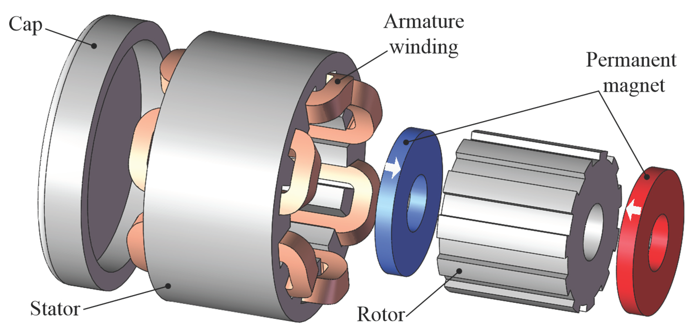
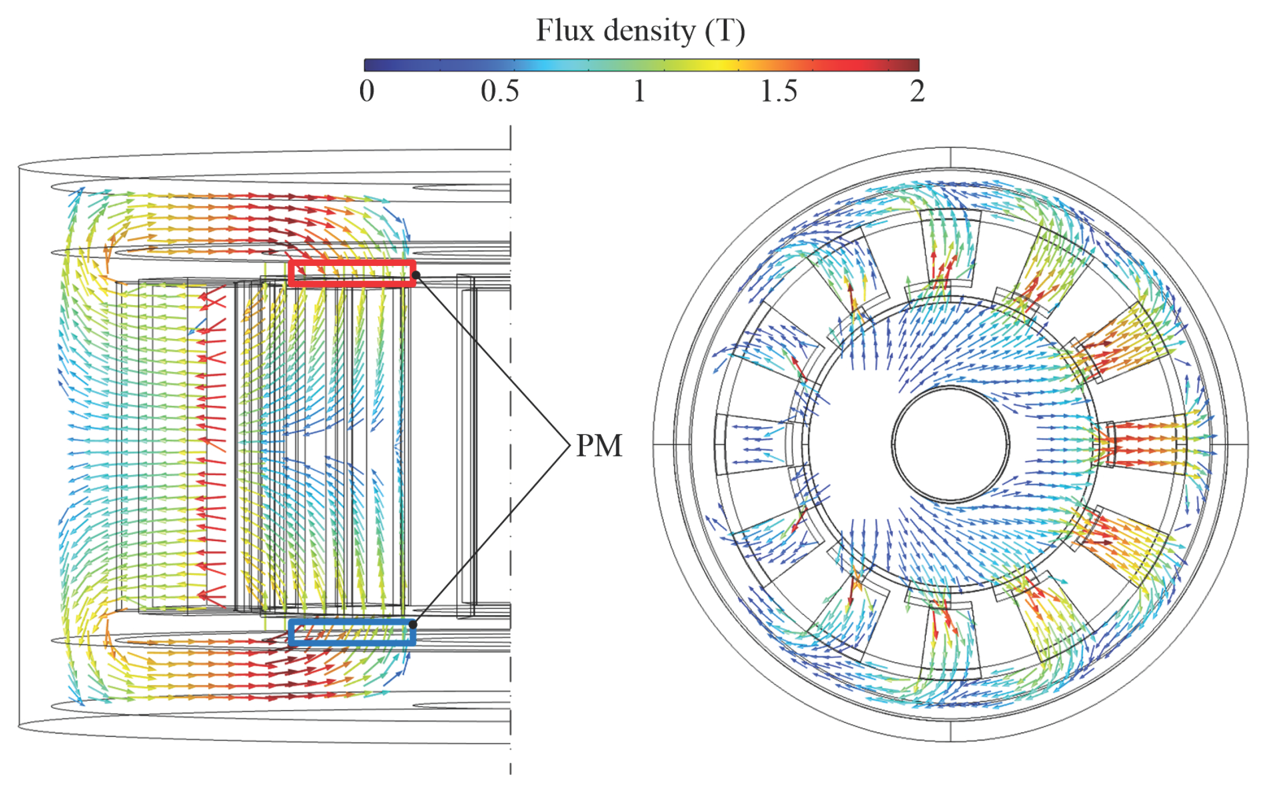
2. Machine Structure and Operation Principle
3. Inductance Matrix Modeling
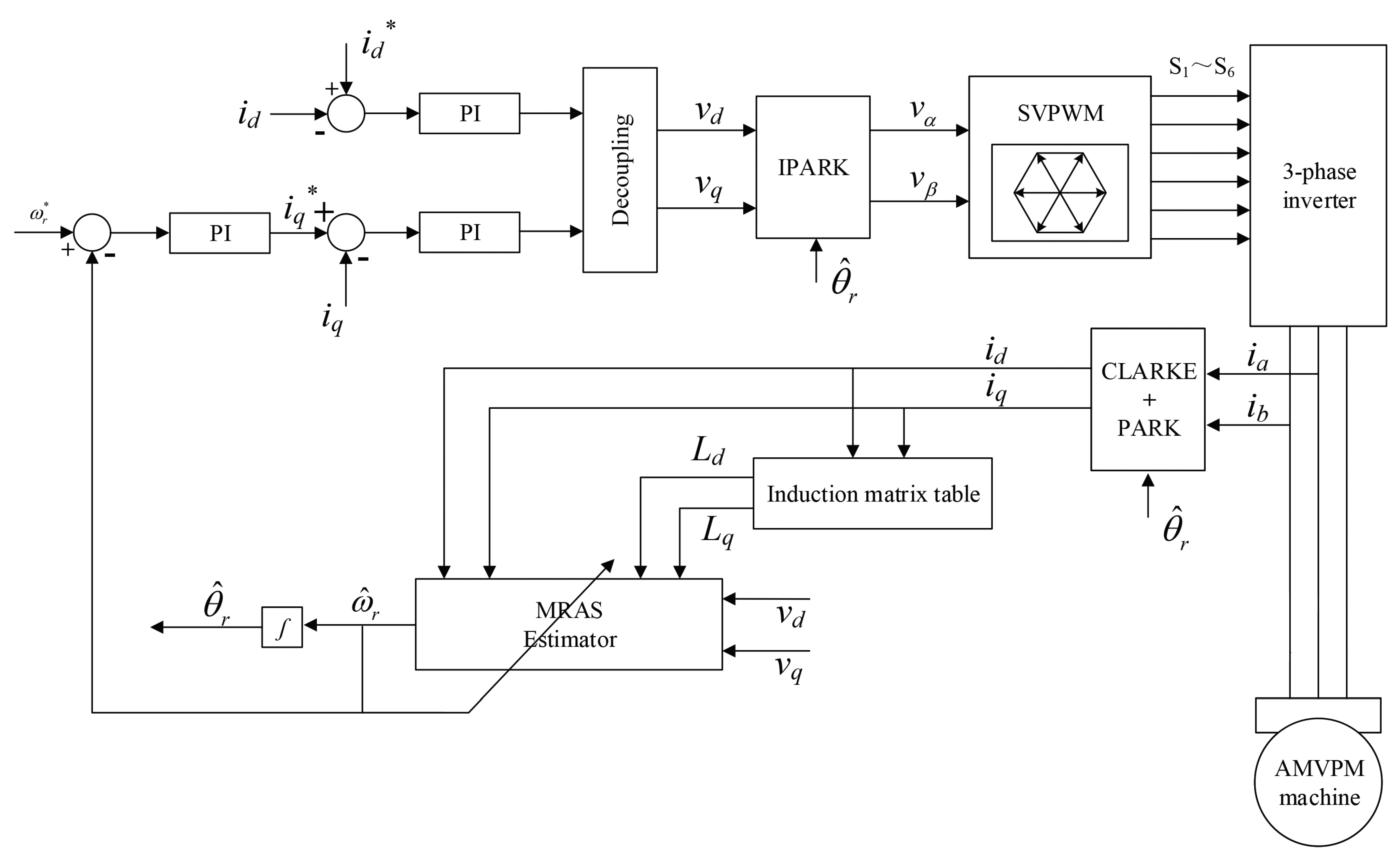
4. Structure of Field-Oriented Control System
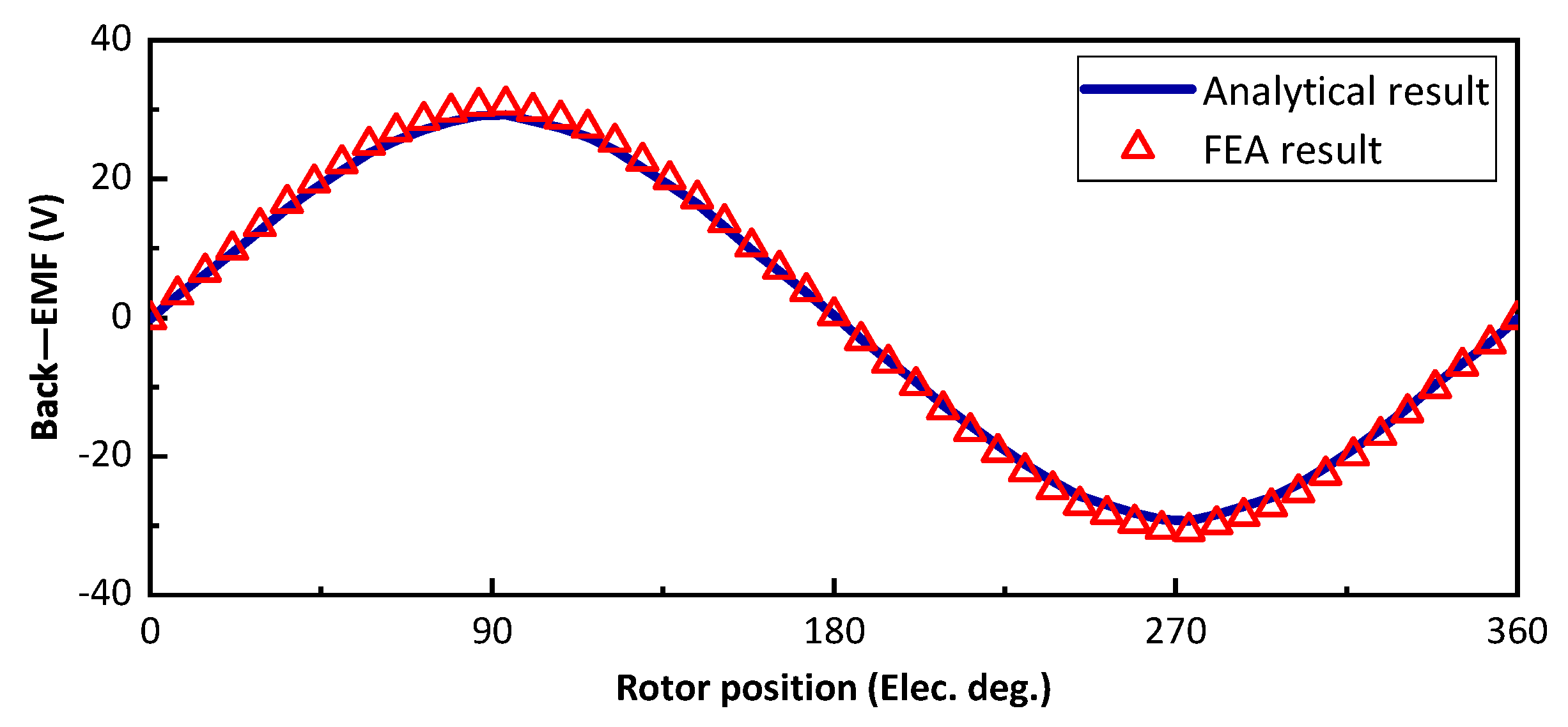
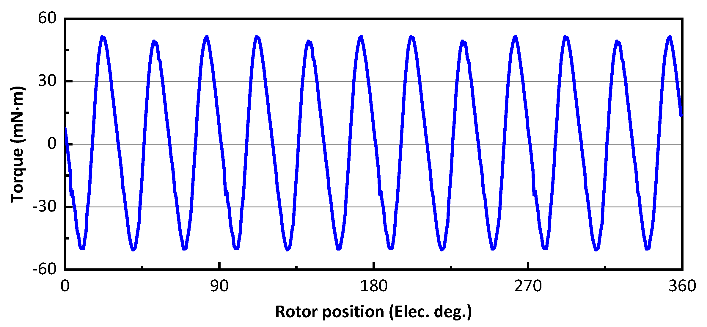
5. Simulation Results
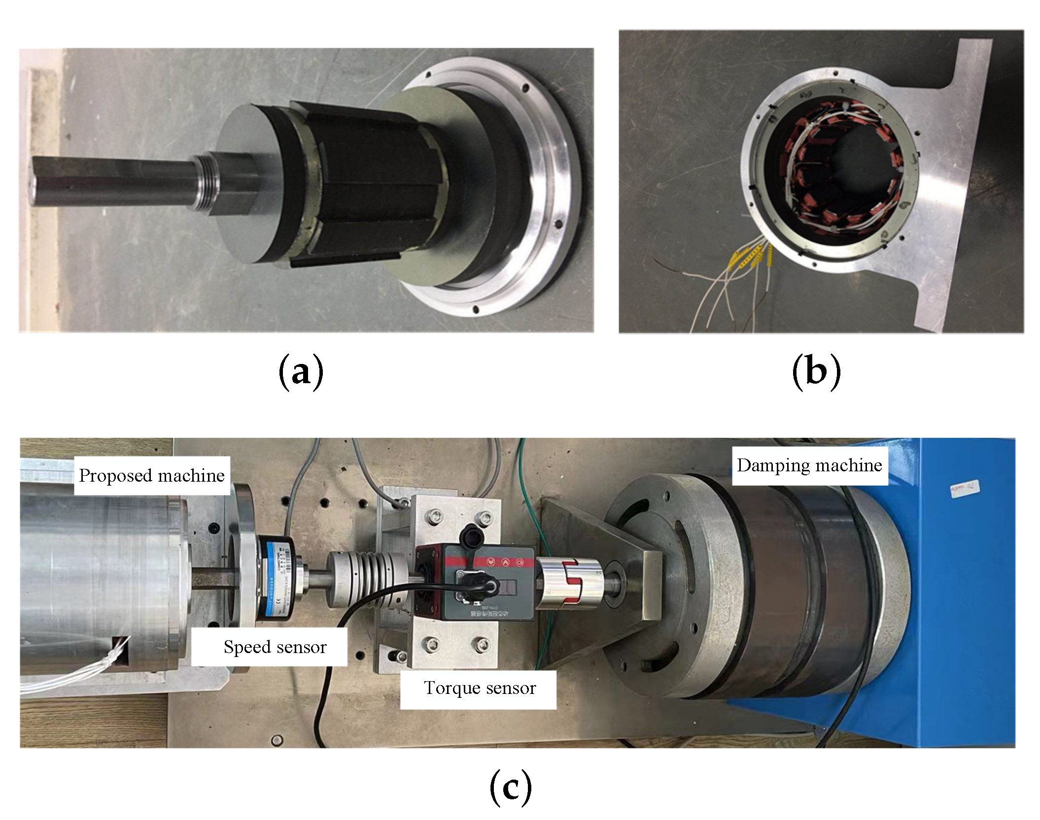
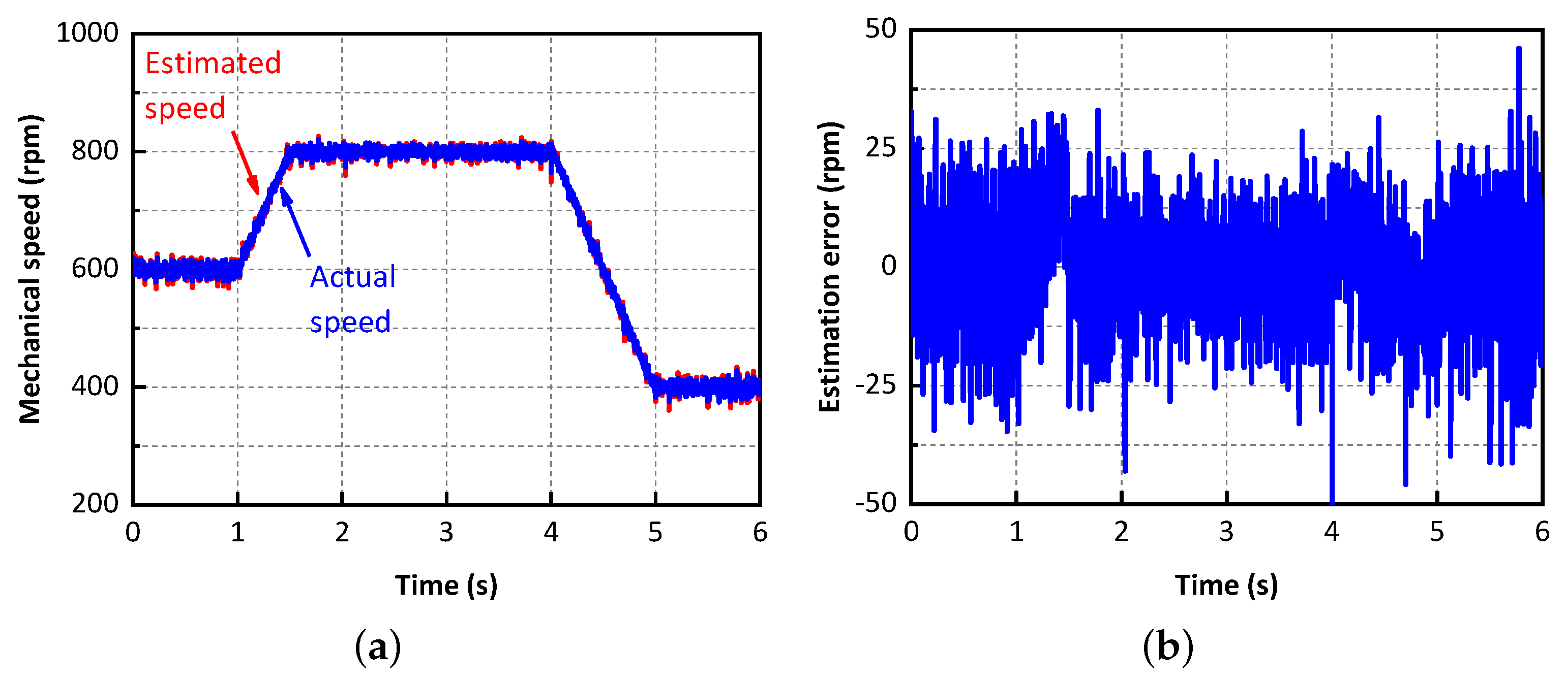
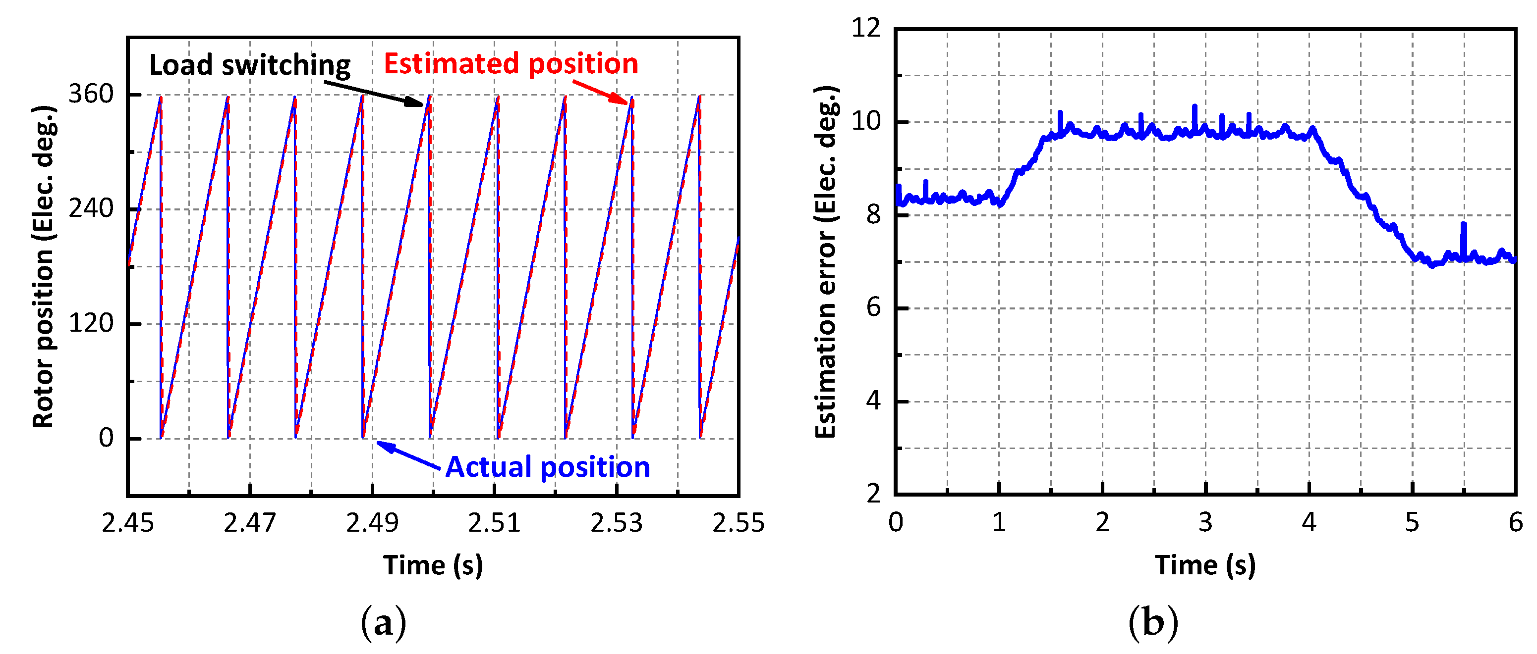
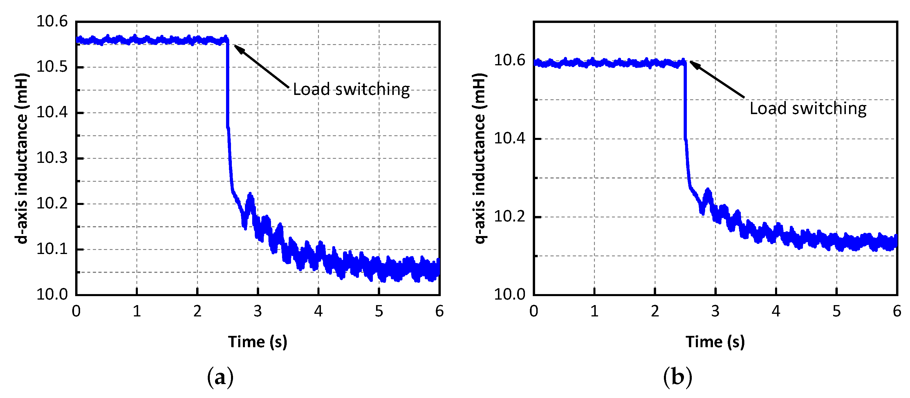
6. Experiment Validation
7. Discussion
Author Contributions
Funding
Institutional Review Board Statement
Informed Consent Statement
Data Availability Statement
Conflicts of Interest
References
- Ishizaki, A.; Tanaka, T.; Takasaki, K.; Nishikata, S. Theory and optimum design of PM Vernier motor. In Proceedings of the 7th International Conference on Electrical Machines and Drives, Durham, UK, 11–13 September 1995; pp. 208–212. [Google Scholar]
- Li, D.; Qu, R.; Lipo, T.A. High-Power-Factor Vernier Permanent-Magnet Machines. IEEE Trans. Ind. Appl. 2014, 50, 3664–3674. [Google Scholar] [CrossRef]
- Jang, D.; Chang, J. Design of a Vernier Machine With PM on Both Sides of Rotor and Stator. IEEE Trans. Magn. 2014, 50, 877–880. [Google Scholar] [CrossRef]
- Li, D.; Qu, R.; Li, J.; Xu, W. Design of consequent pole toroidal winding outer rotor Vernier permanent magnet machines. In Proceedings of the 2014 IEEE Energy Conversion Congress and Exposition, Pittsburgh, PA, USA, 14–18 September 2014; pp. 2342–2349. [Google Scholar]
- Kim, B.; Lipo, T.A. Operation and design principles of a PM Vernier motor. IEEE Trans. Ind. Appl. 2014, 50, 3656–3663. [Google Scholar] [CrossRef]
- Liao, Y.; Liang, F.; Lipo, T.A. A novel permanent magnet motor with doubly salient structure. IEEE Trans. Ind. Appl. 1995, 3, 1069–1078. [Google Scholar] [CrossRef]
- Cheng, M.; Chau, K.T.; Chau, C.C.; Zhou, E.; Huang, X. Nonlinear varying-network magnetic circuit analysis for doubly salient permanent-magnet motors. IEEE Trans. Magn. 2000, 36, 339–348. [Google Scholar] [CrossRef]
- Cheng, M.; Chau, K.T.; Chau, C.C. Design and analysis of a new doubly salient permanent magnet motor. IEEE Trans. Magn. 2001, 37, 3012–3020. [Google Scholar] [CrossRef] [Green Version]
- Hua, W.; Zhu, X.; Wu, Z. Influence of coil pitch and stator-slot/rotor-pole combination on back EMF harmonics in flux-reversal permanent magnet machines. IEEE Trans. Energy Convers. 2018, 33, 1330–1341. [Google Scholar] [CrossRef]
- Li, H.; Zhu, Z. Influence of magnet arrangement on performance of flux reversal permanent magnet machine. In Proceedings of the 2017 IEEE International Electric Machines and Drives Conference, Miami, FL, USA, 21–24 May 2017; pp. 1–8. [Google Scholar]
- Li, H.; Zhu, Z. Optimal number of magnet pieces of flux reversal permanent magnet machines. IEEE Trans. Energy Convers. 2019, 34, 889–898. [Google Scholar] [CrossRef]
- Rauch, S.E.; Johnson, L.J. Design principles of flux-switching alternators. AIEE Trans. Power Appl. Syst. 1955, 74, 1261–1268. [Google Scholar]
- Chen, J.; Zhu, Z.; Iwasaki, S.; Deodhar, R.P. A novel E-core switched-flux PM brushless ac machine. IEEE Trans. Ind. Appl. 2011, 47, 1273–1282. [Google Scholar] [CrossRef]
- Zhu, Z.; Chen, J.; Pang, Y.; Howe, D.; Iwasaki, S.; Deodhar, R. Analysis of a novel multi-tooth flux-switching PM brushless ac machine for high torque direct-drive applications. IEEE Trans. Magn. 2008, 44, 4313–4316. [Google Scholar] [CrossRef]
- Xu, B.; Wu, L.; Ma, J.; Pierre, D.P.; Huang, X.; Qiu, L.; Fang, Y. A Novel Axially Magnetized Vernier Permanent-Magnet Machine. IEEE Trans. Magn. 2021, 57, 1–5. [Google Scholar] [CrossRef]
- Xu, B.; Ma, J.; Wu, L.; Huang, X.; Fang, Y. Investigation of Novel Axially Magnetized Vernier Permanent-Magnet Machine in Cascade Structure. In Proceedings of the 23rd International Conference on Electrical Machines and Systems, Hamamatsu, Japan, 24–27 November 2020; pp. 1246–1250. [Google Scholar]
- Jang, J.; Ha, J.; Ohto, M.; Ide, K.; Sul, S. Analysis of permanent-magnet machine for sensorless control based on high-frequency signal injection. IEEE Trans. Ind. Appl. 2004, 40, 1595–1604. [Google Scholar] [CrossRef]
- Liu, J.; Zhu, Z. Novel Sensorless Control Strategy With Injection of High-Frequency Pulsating Carrier Signal Into Stationary Reference Frame. IEEE Trans. Ind. Appl. 2014, 50, 2574–2583. [Google Scholar] [CrossRef]
- Caruana, C.; Asher, G.; Sumner, M. Performance of HF signal injection techniques for zero-low-frequency vector control of induction Machines under sensorless conditions. IEEE Trans. Ind. Electron. 2006, 53, 225–238. [Google Scholar] [CrossRef]
- Schauder, C. Adaptive speed identification for vector control of induction motors without rotational transducers. IEEE Trans. Ind. Appl. 1992, 28, 1054–1061. [Google Scholar] [CrossRef]
- Rashed, M.; MacConnell, P.; Stronach, A.; Acarnley, P. Sensorless indirect-rotor-field-orientation speed control of a permanent-magnet synchronous motor with stator-resistance estimation. IEEE Trans. Ind. Electron. 2007, 54, 1664–1675. [Google Scholar] [CrossRef]
- Nahid-Mobarakeh, B.; Meibody-Tabar, F.; Sargos, F. Mechanical sensorless control of PMSM with online estimation of stator resistance. IEEE Trans. Ind. Appl. 2004, 40, 457–471. [Google Scholar] [CrossRef]
- Mese, E.; Torrey, D.A. An approach for sensorless position estimation for switched reluctance motors using artifical neural networks. IEEE Trans. Power Electron. 2002, 17, 66–75. [Google Scholar] [CrossRef]
- Shi, Y.; Sun, K.; Huang, L. Online identification of permanent magnet flux based on extended kalman filter for IPMSM drive with position sensorless control. IEEE Trans. Ind. Electron. 2012, 59, 4169–4178. [Google Scholar] [CrossRef]
- Zhao, Y.; Qiao, W.; Wu, L. Improved rotor position and speed estimators for sensorless control of interior permanent-magnet synchronous machines. IEEE Trans. Emerg. Sel. Top. Power Electron. 2014, 2, 627–639. [Google Scholar] [CrossRef]
- Solsona, J.; Valla, M.I.; Muravchik, C. A nonlinear reduced order observer for permanent magnet synchronous motors. IEEE Trans. Ind. Electron. 1996, 2, 492–497. [Google Scholar] [CrossRef]
- Bolognani, S.; Oboe, R.; Zigliotto, M. Sensorless full-digital PMSM drive with EKF estimation ofspeed and rotor position. IEEE Trans. Ind. Electron. 1999, 2, 184–191. [Google Scholar] [CrossRef]
- Morimoto, S.; Kawamoto, K.; Sanada, M.; Takeda, Y. Sensorless control strategy for salient-pole PMSM based on extended EMF in rotating reference frame. IEEE Trans. Ind. Appl. 2002, 38, 1054–1061. [Google Scholar] [CrossRef]
- Heller, B.; Hamata, V. Harmonic Field Effects in Induction Machines; Elsevier: Amsterdam, The Netherlands, 1977; pp. 54–67. [Google Scholar]
- Gaussens, O.B.; Hoang, E.; Saint-Michel, J.; Manfe, P.; Lecrivain, M.; Gabsi, M. Magnetic field solution in doubly slotted airgap of conventional and alternate field-excited switched-flux topologies. IEEE Trans. Magn. 2013, 49, 5083–5096. [Google Scholar] [CrossRef]


| Parameters | Value |
|---|---|
| Stator outer diameter | 140 mm |
| Split ratio | 0.6 |
| Stator slot number | 12 |
| Rotor slot number | 7 |
| Air-gap length | 1 mm |
| Core length | 50 mm |
| PM thickness | 9 mm |
| PM type | NMX-S38EH (60 C) |
| Silicon steel type | 35WW400 |
| Parameters | Value |
|---|---|
| Stator resistance | 0.34 |
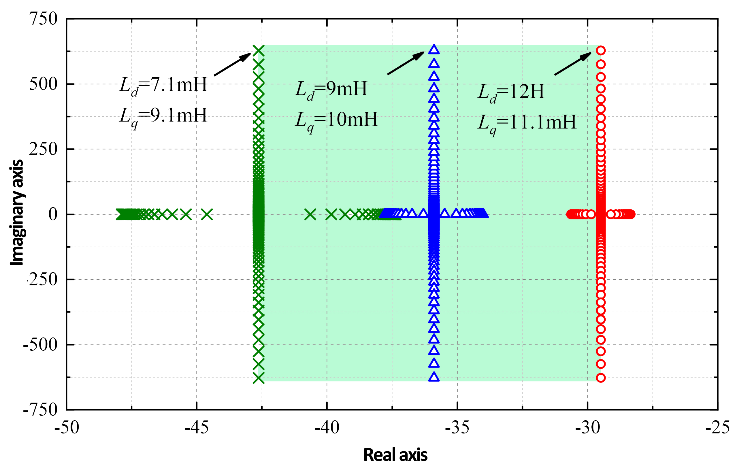
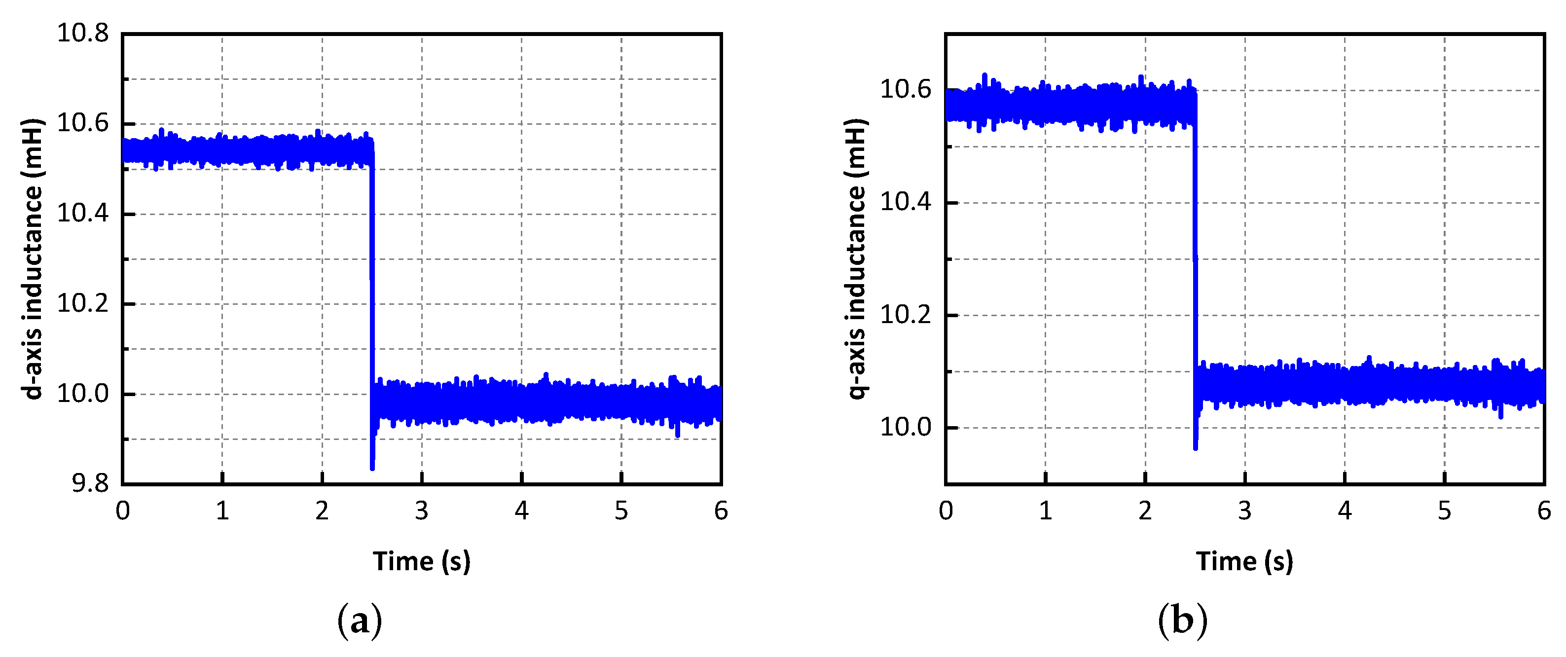
| d-axis inductance | 7.1–12 mH |
| q-axis inductance | 9.1–11.1 mH |
| Excitation flux linkage | 0.067 Wb |
| Rated speed | 600 rpm |
| Open-circuit back-EMF | 29.2 V |
| Rated current | 5.2 A |
| Rated torque | 3 Nm |
| Electrical period | 7 |
Publisher’s Note: MDPI stays neutral with regard to jurisdictional claims in published maps and institutional affiliations. |
© 2022 by the authors. Licensee MDPI, Basel, Switzerland. This article is an open access article distributed under the terms and conditions of the Creative Commons Attribution (CC BY) license (https://creativecommons.org/licenses/by/4.0/).
Share and Cite
Xu, B.; Ma, J.; Wu, Q.; Qiu, L.; Liu, X.; Luo, C.; Fang, Y. Sensorless Control Strategy of Novel Axially Magnetized Vernier Permanent-Magnet Machine. Energies 2022, 15, 5470. https://doi.org/10.3390/en15155470
Xu B, Ma J, Wu Q, Qiu L, Liu X, Luo C, Fang Y. Sensorless Control Strategy of Novel Axially Magnetized Vernier Permanent-Magnet Machine. Energies. 2022; 15(15):5470. https://doi.org/10.3390/en15155470
Chicago/Turabian StyleXu, Bowen, Jien Ma, Qiyi Wu, Lin Qiu, Xing Liu, Chao Luo, and Youtong Fang. 2022. "Sensorless Control Strategy of Novel Axially Magnetized Vernier Permanent-Magnet Machine" Energies 15, no. 15: 5470. https://doi.org/10.3390/en15155470
APA StyleXu, B., Ma, J., Wu, Q., Qiu, L., Liu, X., Luo, C., & Fang, Y. (2022). Sensorless Control Strategy of Novel Axially Magnetized Vernier Permanent-Magnet Machine. Energies, 15(15), 5470. https://doi.org/10.3390/en15155470