Article

Modeling and Simulation of Electric Motors Using Lightweight Materials

by
Nikita Gobichettipalayam Boopathi
1,
Manoj Shrivatsaan Muthuraman
1,
Ryszad Palka
2,
Marcin Wardach
2,*,
Pawel Prajzendanc
2,
Edison Gundabattini
3,*,
Raja Singh Rassiah
4 and
Darius Gnanaraj Solomon
5
1
Department of Manufacturing Engineering, School of Mechanical Engineering, Vellore Institute of Technology (VIT), Tamil Nadu, Vellore 632 014, India
2
Faculty of Electrical Engineering, West Pomeranian University of Technology in Szczecin, Sikorskiego 37, 70-313 Szczecin, Poland
3
Department of Thermal and Energy Engineering, School of Mechanical Engineering, Vellore Institute of Technology (VIT), Tamil Nadu, Vellore 632 014, India
4
Advanced Drives Laboratory, Department of Energy and Power Electronics, Vellore Institute of Technology, Vellore 632 014, India
5
Department of Design and Automation, School of Mechanical Engineering, Vellore Institute of Technology (VIT), Tamil Nadu, Vellore 632 014, India
*
Authors to whom correspondence should be addressed.
Energies 2022, 15(14), 5183; https://doi.org/10.3390/en15145183
Submission received: 15 June 2022 / Revised: 11 July 2022 / Accepted: 15 July 2022 / Published: 17 July 2022
(This article belongs to the Section F: Electrical Engineering)

Abstract

:
Electric motors are utilitarian devices of great potential as they can limit the amount of pollution by drastically reducing the release of harmful gases. The implementation of the right type of advanced materials plays a vital role in the amelioration of modern automobiles while maintaining and/or improving the performance and efficiency of the electric motor. The use of lightweight materials could result in a better-performing vehicle that can be much less heavy. The replacement of regular cast iron, steel, and aluminum with lightweight materials such as fiber-reinforced polymer, carbon fiber, and polymer composites can reduce the weight of the motor without impacting its performance and improve its energy-saving capacity. This paper explores a way to reduce motor weight by employing a PA6GF30 30% glass fiber-reinforced polymer casing to reduce the weight of the motor while making cooling system modifications. This material was applied to the motor casing, which resulted in a significant reduction in weight compared to the water-cooled electric motor of aluminum (Alloy 195 cast) casing.

1. Introduction

The rise in usage of lightweight electric motors has been snowballing lately in order to reduce pollution and carbon emissions, as well as promote green mobility [1]. Lightweight electric motors also reduce the overall weight of the vehicle and power consumption, thus improving vehicle performance [2]. Over the years, proven lightweight materials such as fiber-reinforced polymer, carbon fiber, and polymer composites have been used in various applications to enhance their efficiency [3,4,5]. They are being researched and implemented especially in the aviation field since weight is a very important factor here. In this research, only air-based cooling and water-cooled systems were discussed, but there are various other options and techniques to lower the temperature of machines such as winding cooling, heat conduction enhancement, phase changing materials, and hybrid cooling systems. Many research studies have explored different possibilities through which the motor’s weight can be reduced by applying several lightweight materials to different parts of the motor [6].
It has also been observed that most high-power applications of electric motors, such as high-performance cars (e.g., Tesla and Porsche) employ fluid-cooled electric motors for better cooling efficiency compared to fan cooling, which also takes up space and can lead to overheating. Electric motors are used for various applications ranging from industrial to domestic applications, and induction motors (rotating or linear) are the most used units [7,8,9,10,11]. Water-cooling systems might suffer from leakage issues if not properly designed and maintained. Additionally, the design of the water flow system is more complex when compared to the air-cooling system, and its initial costs are higher. The parts of water-cooled systems might add complexity, weight, and cost of the engine. This system is better for higher-power machines that produce high waste heat but can move more weight. Another main complexity in water-cooled motors is the requirement of a pump, a pipe to transport water, and a radiator, when compared to the requirement of only a fan in the air-cooled motor to expel excess heat out of the motor. Figure 1 shows an example of a typical rotating induction motor [12].
In this paper, different possibilities are explored that could be applied to reduce the weight of the electric motor (the study is specifically performed for a fluid-cooled motor) by analysis of various research papers and an in-depth study of all concepts. Through this process, a method is proposed that could potentially reduce the weight of the motor due to a change in its cooling system and the choice of a suitable lightweight material for the casing, i.e., carbon fiber0reinforced polymer (CFRP).
Generally, induction motors comprise major components such as stator coils, which are usually made of copper, and the stator frame, which is generally made of alloy steel. The stator core has high-grade stampings of silicon steel, the rotor is also usually made of similar alloy steel materials, rotor end rings are made of copper or aluminum, and the shaft is made of steel. In this paper, a change in the outer casing material of the induction motor is explored with the application of various lightweight materials such as fiber-reinforced polymers.
The design of electric motors by incorporating both lightweight and cooling systems facilitates the development of efficient electric motors. These design and optimization methods have already been used by the authors in the construction of various machines with permanent magnets, including hybrid excited machines [13,14,15]. These papers indicated the use of soft magnetic materials [16,17,18] to optimize the magnetic cores of machines in order to obtain the optimal distribution of the magnetic field, as well as to reduce the mass of the machines.

2. Motor Selection

A 0.5 HP motor was selected for the research—a typical fan-cooled induction motor with round axial fins. This motor was chosen for the study to test how the efficiency of the water-cooling system is better than that of the fan-cooling system. This motor was used as a reference to design a fan-cooled motor with Ansys Motor-CAD. Motor-CAD is a utilitarian software used to perform thermal, electromagnetic, and mechanical analyses for different types of electric motors. Motor designs and input data to perform the required analyses can be efficiently modified and customized as per the needs of the user, helping them to effectively perform analysis calculations for different motors [19].
The reference motor was disassembled, its parts were weighed, and its dimensions were measured (Table 1).
Figure 2 and Figure 3 show references of the work conducted in weighing and measuring the main parts of the motor. After the dimensions of the various parts of the motor were measured and recorded, they were used to design the motor with Motor-CAD. Some of the main motor dimensions are listed in Table 1, and Table 2 lists the specifications of the analyzed single-phase induction motor.

3. Design of Single-Phase Induction Motor

This section provides the calculation of the basic motor parameters. Dimensions of the induction motor’s stator frame were designed on the basis of the rating of the motor. Considering all the factors that affect the parameters of the machine, the design parameters and all constants were obtained from standard data [20,21].
D 0 2   L = 16.5 × C 0 × h p r p m × K f K t × 10 6 = 2249   cm 3 ,  
where hp is the rated output power of the machine, rpm is the rated speed of the machine, the output coefficient C 0 is 0.29 T, and the constants K f and K t are 0.96 and 1.42, respectively.
The proportion between D0 and L is given as
L = 0.3   D 0 ,  
where D 0 is the outer diameter of the motor (0.2 m), and L is the stator stack length of the motor.
To determine the maximum airgap flux density, the ratio between the stator interior bore diameter, D i , and the external or outer diameter, D 0 , is required. Furthermore, it depends on the number of poles, magnetic flux densities, and electric current density loadings. As the frames for single phase come into standardized sizes, D 0 is selected from the standard data. The ratio for the four-pole machine is given as follows [20]:
D i / D 0 = 0.59 .  
Thus, the stator interior bore diameter, D i , is assumed as 0.118 m. A punching parallel-sided teeth stator with a flat-bottom slot was chosen for the present case of a single-phase induction motor. The various parameters including slot opening ( b 10 ), tooth width ( b t 1 ), slot top width ( b 11 ), core depth ( d c 1 ), slot depth ( h 14 ), slot bottom width ( b 13 ), and airgap length ( l g ) are given below.
Slot   Opening   ( b 10 ) = 0.000648 + 0.000175 D i = 0.00278   m .
The slot tip depth, h 10 = 0.0007   m , was obtained from [13]. The mouth depth, h 11 , was considered as 1.3 times the slot tip depth ( h 11 = h 10 × 1.3 = 0.0009   m ). As per [9], the mouth depth was between 1 and 1.5 times the slot tip depth.
Tooth   width   ( b t 1 ) = ( 1.27 + 0.035 D i ) D i S 1 = 0.0077   m .
Considering flat-bottomed trapezoidal slots with parallel-sided teeth, the slot top width ( b 11 ) , is given by
Slot   top   width   ( b 11 ) = π ( D i + 2 ( h 10 + h 11 ) S 1 b t 1 = 0.0077   m .
Core   depth   ( d c 1 )   = B t B C × S 1 × b t 1 π × P = 0.0194   m .
Slot   depth   ( h 14 ) = 0.5 ( D 0   D i ) × ( h 10 + h 11 + d c 1 ) = 0.019   m .
Slot   bottom   width   ( b 13 ) = b 11 + h 14 tan α = 0.0127   m .
Airgap   length   ( l g )   = 0.013 + 0.0042 D i 2 = 0.000382   m .

4. Methodology

The first step was to analyze and study different ways of motor weight reduction, to collect information on different lightweight materials that can be used for the construction of the motor casing, and to decide on a solution for the problem of weight reduction of the motor (liquid/water-cooled). Using the dimensions obtained through measurement of the parts by a Vernier caliper, the next step was to design the motor components with Motor-CAD and to perform thermal analysis simulations of the motor [22] to check its functioning/performance to compare the cooling system efficiency of fan-cooled and fluid/water-cooled system designs. One of the most important steps was choosing the lightweight outer casing material to reduce the motor weight. Required modifications in the cooling system design (fluid/water-cooled) that support lightweight outer casing were also made. Moreover, a thermal analysis of the new motor was performed to check its cooling system efficiency functioning and compare it with the fluid/water-cooled motor with lightweight casing. The last step was to analyze and compare the results of the fluid/water-cooled motor before applying the lightweight casing, and then recording the reduction in weight observed in the lightweight fluid/water-cooled motor.

4.1. Electric Motor Designed on Motor-CAD (Fan Cooling System)

The motor chosen for the research work is shown in Figure 4, and the model of the motor generated using the Motor-CAD software is shown in Figure 5. In this research, three types of electric motors were studied: Case-1 (air-cooled motor), Case-2 (water-cooled motor with aluminum (Alloy 195 cast) casing), and Case-3 (water-cooled motor with PA6GF30).

4.2. Electric Motor Designed with Motor-CAD (Water Jacket Cooling System)

Figure 6 shows the designed water-cooled motor. The dimensions for both motors (air-cooled and water-cooled) were the same, with the only difference being the change in the cooling system from fan cooling to an axial housing water jacket cooling system. The arrows indicate the flow of water through the housing jacket, and the cowling was removed.

4.3. Water-Cooled Motor with Lightweight Material PA6GF30 as Casing

Many studies have explored various ways to reduce the weight of the motor by introducing and implementing various material changes in different parts of the motor such as the rotor, shaft, and casing [23]. This project’s study focuses on changing the casing material of the water-cooled electric motor to reduce its weight. Different materials were researched to determine which material works best to achieve the project’s objective. Traditionally, motor housings are made of cast iron since it is cheap and has the required mechanical properties to provide strength and damping capacity to withstand vibrations. Since the damping capacity of the new material is almost equal to that of the traditional materials, the new material (PA6GF30) would withstand the high vibrations. In terms of material properties, CFRP and PA6GF30 are similar as the latter is a glass fiber-reinforced polymer (GFRP). The damping capacity is almost the same as of traditional materials. The mechanical properties of the new material such as the tensile strength and Young’s modulus are higher compared to cast iron; hence, the housing is reliable. Table 3 compares the mechanical properties of cast iron with CFRP. It can be found that CFRP has a high tensile strength and high Young’s modulus. The compressive stress and the damping capacity are comparable to those of cast iron. CFRP being a lightweight material is a good replacement for cast iron and also reliable since it has equal or better strength and damping capacity to withstand vibrations. Table 3 gives a comparison of the mechanical properties of the traditional and proposed materials [24,25,26].
Cast-iron housings are made through the casting process and the proposed new material housings are made through molding of composite materials. Even though the material cost of cast iron is lower compared to the new material, the processing cost of the traditional casting process is higher since it requires high-temperature furnaces, handling of molten metal at high temperature, and the manufacture of molds. Since composites require only a mixer for mixing the fibers with the binder at room temperature and the mix is laid on a wooden mold or a mold made of a plaster of Paris, the processing cost is lower. When we add the material cost, processing cost, the labor cost, and overhead expenses, the cost of the housing made of the proposed new PA6GF30 is expected to be lower than that of the housing made with traditional materials through traditional processes. Table 4 gives an overview of different possible material properties.
Among the materials presented, PA6GF30 was chosen to replace the aluminum (Alloy 195 cast) casing of the water-cooled electric motor. PA6GF30 is a 30% glass fiber-reinforced polyamide. Its major advantages are its high strength, good dimensional stability, and wonderful heat deflection temperature. Thus, PA6GF30 was applied as the casing material, and then thermal analysis was performed to check if the cooling efficiency was negatively impacted. The latest motor housing and cooling jacket research focused on reducing the thermal contact resistance, using new materials with improved thermal performance and optimized channel geometries and designs for reducing the pressure drop losses, using nanofluid-based cooling systems, and increasing the heat transfer on the convection surfaces [27].

5. Results and Discussion

5.1. Radial and Axial Views of Fan-Cooled Motor along with Path of Air Flow from Fan Cooling System

Figure 7 shows the radial and axial views for the air-cooled motor. The radial view of the motor shows the housing type-axial fins (the windings, stator, and rotor), and the axial view shows the direction of the air flow with the help of the arrows indicated.

5.2. Performance of FEM Thermal Analysis of Motor (Fan-Cooled)

Table 5 shows the input parameters for the thermal analysis performed on the fan-cooled motor. FEM simulations were performed for the air-cooled motor after the process of air cooling with the help of the cooling fan in the motor. The radial view and axial view of the motor after the FEM analysis are shown in Figure 8 and Figure 9, respectively.
Results of the FEM analysis for the air-cooled motor are shown in Table 6.
The maximum and minimum temperatures of both axial and radial parts of the motor were recorded and included in the above table. Similar results were obtained in thermal analyses performed in [28]. The EEC (electric engine cooling) fan cooling system motor thermal analysis presented there showed a temperature range obtained for a similar fan cooling system whose results ranged from 100 °C to over 270 °C. Table 7 indicates the values obtained for the EEC motor used in [28]. The data obtained in that study were compared with the data obtained in this research to show the cooling efficiency of the fan-cooled system in a coherent manner.

5.3. Radial and Axial Views of Motor along with Path of Water Flow for Water-Cooled Motor with Housing Water Jacket

The radial and axial views of the water-cooled motor with aluminum casing are shown in Figure 10. In the axial view, the arrows seen clearly depict the flow of water through the casing jacket, and no cowling is present.

5.4. Thermal Analysis of Water-Cooled Motor with Aluminum (Alloy 195 Cast) Casing

Table 8 shows the input parameters for thermal analysis of the water-cooled motor with aluminum. Here, the inlet temperature was taken as 15 °C considering that this experiment was carried out at a location of lower environmental temperature such as a hill station. For this study, locations with lower temperatures such as hill stations were chosen to perform the study. As the temperatures in those regions are generally low, a suitable ambient temperature for the water inlet temperature of 15 °C is allowed to be maintained, and no external cooling devices are used. Many different countries also exhibit similar ranges of environmental temperatures. Therefore, when the cooling systems are simulated, the temperatures considered were seen as suitable and easier to carry out the research with.
The specific heat capacity and fluid properties obtained for the coolant used are shown in Table 9 and Figure 11. The cooling liquid used here being water has quite a high specific heat capacity at 4182 J/kg·°C, which makes it an excellent cooling fluid for heat dissipation.
Figure 12 and Figure 13 show the radial and axial views of the water-cooled motor with aluminum (Alloy 195 cast) casing after the FEM analysis, revealing a significant drop in temperatures with the temperature reduction at the highest temperature being around 50.4% when compared to the air-cooled motor. The total weight of the water-cooled motor was 12.1 kg.
Table 10 shows the significant reduction in temperatures when using a water-based cooling system in the water-cooled motor with aluminum (Alloy 195 cast) casing. The highest temperature observed here was 124 °C, which is 50.4% lower than the highest temperature observed in the thermal analysis of the fan-cooled motor (250 °C).
Similarly, in the study performed by Timo Müller, Gustavo Blazek, and Frank Henning in [5], a similar thermal analysis was observed where a liquid-cooled motor showed a maximum of 84 °C casing temperature, as seen in Figure 13, with the water temperature for the simulation set at a constant 40 °C with a flow rate between 5 L/min and 10 L/min, whereas the motor present in this study showed a maximum casing temperature of around 65 °C for the same parameters as in the motor used in [5]. For parameters employed as per this study, the maximum casing temperature was found to be approximately 48 °C. Through this, the better cooling efficiency of the water-cooling system can be understood.
Table 11 presents a comparative analysis for two water-cooled motors obtained in two distinct studies. This comparison was used to prove the validation of the research performed in this study.

5.5. Output Data Obtained for Motor Thermal Analysis (Comparison of Fan-Cooled and Water-Cooled Motor with Aluminum Casing)

Table 12 and Table 13 give a coherent comparison of the axial temperatures obtained from the thermal analysis of the fan-cooled induction motor and the water-cooled induction motor with aluminum casing. From the data recorded in these graphs, it can be seen that the water-cooling system offered better cooling efficiency compared to the fan cooling system. The highest temperature along axial direction for the air-cooled motor was 250 °C, whereas that for the water-cooled motor was just 124 °C.
After proving that the water-cooled electric motor had better cooling efficiency, the study chose a suitable lightweight material to replace the aluminum (Alloy 195 cast) casing material of the water-cooled electric induction motor and performed thermal analysis.

5.6. Thermal Analysis of Water-Cooled Electric Motor of Lightweight PA6GF30 Casing

Table 14 shows the input parameters required for the thermal analysis in the water-cooled motor with the PA6GF30 casing. All the important parameters are specified along with the units. These parameters were obtained either from manufacturer’s data or are given following a review of various research studies of similar projects.
Figure 14 and Figure 15 give the radial and axial views of the water-cooled motor with PA6GF30 casing after the FEM analysis. The temperature gradients shown depict the range of temperatures that occurred in the lightweight PA6GF30 casing induction electric motor.
The FEA was performed for the third type of motor designed (water-cooled with PA6GF30 casing). The temperature and weight of the motor were further reduced for Case-3 when compared to Case-1 and Case-2, with a 48.4% reduction in the highest temperature observed in comparison to the fan-cooled motor.
Table 15 presents the results obtained after the thermal analysis performed in the water-cooled electric motor with lightweight PA6GF30 casing. Important parameters such as the temperature range in the radial and axial direction and the total weight of the motor are shown.
Table 15 shows that the total weight of the motor was 9.647 kg, representing a 20.27% reduction in weight for the water-cooled electric motor with PA6GF30 casing in comparison to the water-cooled electric motor with aluminum (Alloy 195 cast) casing. A recorded weight reduction of 2.453 kg was observed when compared with the original weight (12.1 kg) of the aluminum (Alloy 195 cast) casing, i.e., a 20.27% reduction. Thus, the objective of the project, which was to reduce weight of the electric motor (water cooled) by employing a suitable lightweight material and modifying the cooling system to support this material accordingly while maintaining the cooling system efficiency, was fulfilled.
From the data obtained through thermal analysis (Table 16 and Table 17), it can be observed that there was no negative impact in terms of cooling efficiency of the water-cooling system of the electric motor with PA6GF30 casing. The highest temperature observed in the electric motor with aluminum (Alloy 195 Cast) casing was 124 °C, whereas that for the electric motor with PA6GF30 casing was 129 °C.
Table 18 and Table 19 compare the temperature reduction and weight reduction for Case-2 and Case-3 with respect to Case-1. From Table 18, it can be deduced that the water-cooling system’s efficiency was greater since the highest percentage temperature reductions were 50.4% and 48.4% for the water-cooled motors with aluminum (Alloy 195 cast) casing and PA6GF30 casing, respectively, in comparison to the fan-cooled electric motor. Table 18 represents the fulfilment of the objective of this research study (reduction in weight of electric water-cooled induction motor by changing the casing material to a lightweight material). In this case, the PA6GF30 material was selected and applied instead of aluminum (Alloy 195 cast) material casing, which led to a a reduction in weight of 2.453 kg (20.27%).
In order to fully optimize the machine, other analyses must be performed. These include mechanical and electromagnetic analyses. Stresses present in an induction motor are general mechanical stresses on the overall parts of the motor, including stresses caused in rotor bars by centrifugal and magnetic forces, Maxwell electromagnetic stress present between the rotor and stator resulting in noise and vibrations, and thermal stresses and magnetic stresses present mostly in the rotor part of the motor due to the magnetic flux distribution [29,30]. These problems were not considered here as they were considered standard during the initial stages of the design of induction machines. Improving the cooling and reducing the weight of machine parts can substantially reduce the mechanical stress on the machine, and this should ultimately be demonstrated in its final configuration.

6. Conclusions

The thermal analysis revealed how the axial housing water jacket water-cooling system was more effective than the totally enclosed fan-cooled cooling system.
The FEM analysis showed the difference in temperature gradients and temperature ranges. The temperature range of the water-cooled motor (17–124 °C) was much lower than that of the air-cooled motor (104–250 °C); the water-cooled motor with the aluminum casing showed a 50.4% reduction in the highest temperature while the water-cooled motor with PA6GF30 casing showed a 48.4% reduction in the highest temperature, both in comparison with the highest temperature of the fan-cooled motor.
The next step would be to explore and apply materials of lower densities for the motor casing and choose a material that effectively reduces the weight of the motor while remaining compatible with the water-cooling system. It was particularly a challenge to find a lightweight material that not only reduced the weight of the motor but also did not negatively affect the cooling efficiency of the motor. At the current stage of research, the material PA6GF30 was chosen for the motor casing, which resulted in a significant reduction in weight.

Author Contributions

Conceptualization, R.P., E.G., R.S.R. and D.G.S.; methodology, R.P. and E.G.; investigation, N.G.B., M.S.M., R.P., M.W., P.P., E.G., R.S.R. and D.G.S.; writing—original draft preparation, N.G.B., M.S.M. and E.G.; writing—review and editing, R.P., M.W. and E.G. All authors have read and agreed to the published version of the manuscript.
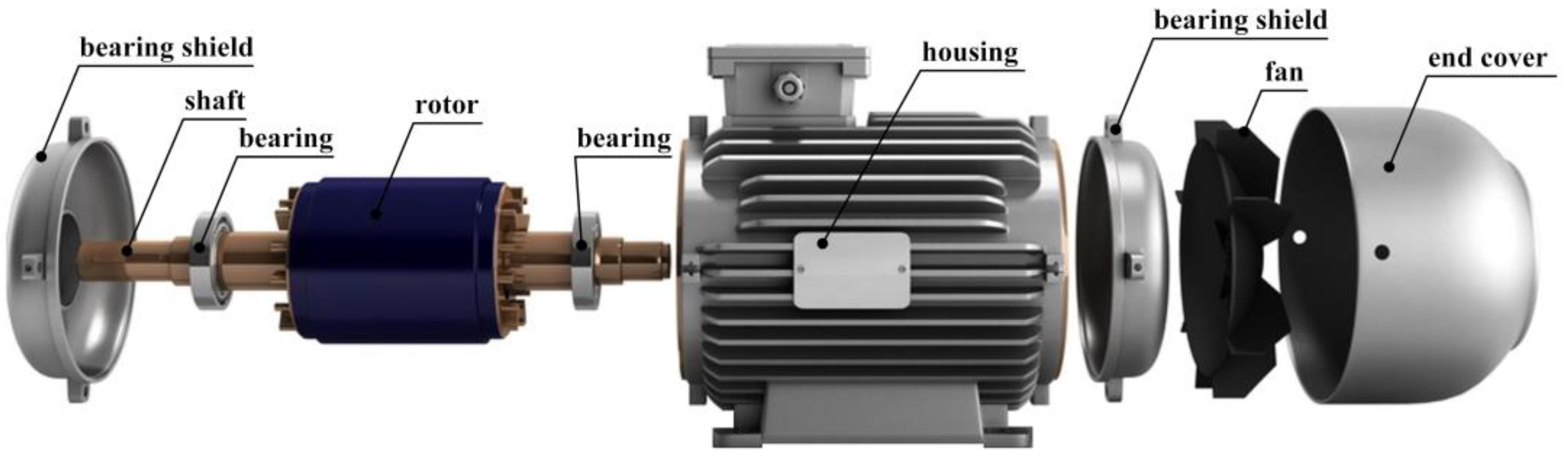
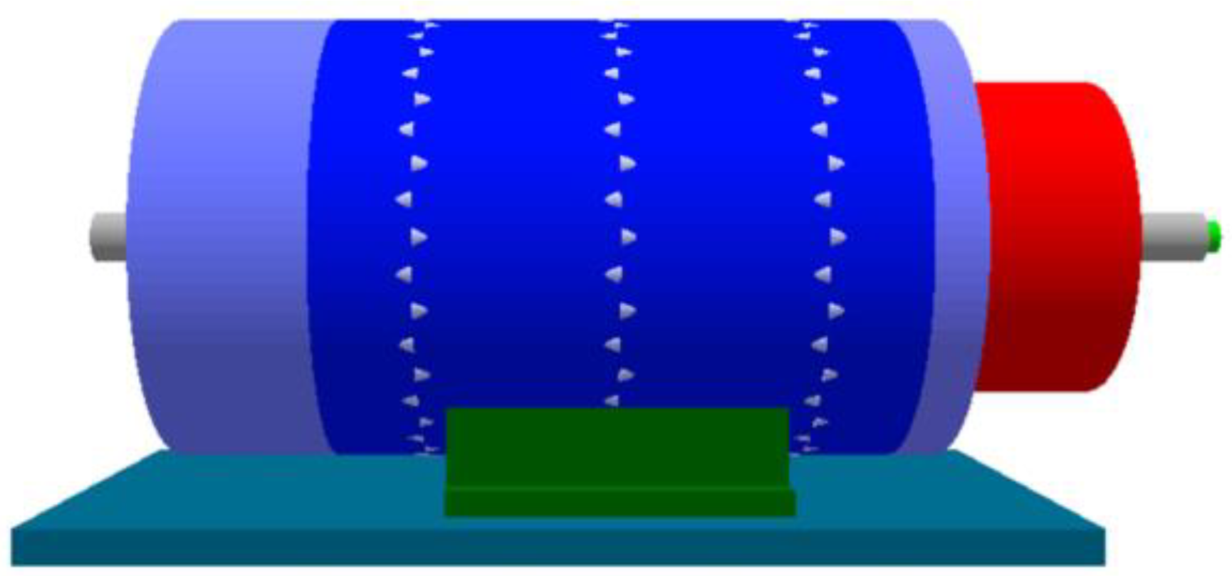
Funding

This research received no external funding.

Institutional Review Board Statement

Not applicable.

Conflicts of Interest

The authors declare no conflict of interest.

Abbreviations

CADComputer-aided design
EECElectric engine cooling
FEAFinite element analysis
FEMFinite element method
PMSMPermanent magnet synchronous machine
CFRPCarbon fiber-reinforced polymer
GFRPGlass fiber-reinforced polymer

References

  1. Koch, S.F.; Peter, M.; Fleischer, J. Lightweight design and manufacturing of composites for high-performance electric motors. Procedia CIRP 2017, 66, 283–288. [Google Scholar] [CrossRef]
  2. Fang, S.; Liu, H.; Wang, H.; Yang, H.; Lin, H. High Power Density PMSM With Lightweight Structure and High-Performance Soft Magnetic Alloy Core. IEEE Trans. Appl. Supercond. 2019, 29, 2. [Google Scholar] [CrossRef]
  3. Sarfraz, M.S.; Hong, H.; Kim, S.S. Recent developments in the manufacturing technologies of composite components and their cost-effectiveness in the automotive industry: A review study. Compos. Struct. 2021, 266, 113864. [Google Scholar] [CrossRef]
  4. Jurca, F.N.; Inte, R.; Martis, C. Optimal rotor design of novel outer rotor reluctance synchronous machine. Electr. Eng. 2020, 102, 107–116. [Google Scholar]
  5. Müller, T.; Blazek, G.; Henning, F. Design concept of a lightweight electric motor casing with support from thermomechanical simulations. Int. J. Automot. Compos. 2016, 2, 2. [Google Scholar] [CrossRef]
  6. Solomon, D.G.; Greco, A.; Masselli, C.; Gundabattini, E.; Rassiah, R.S.; Kuppan, R. A review on methods to reduce weight and to increase efficiency of electric motors using lightweight materials, novel manufacturing processes, magnetic materials and cooling methods. Ann. De Chim.-Sci. Des Matériaux 2020, 44, 1–14. [Google Scholar] [CrossRef]
  7. Sobotka, L.; Pechánek, R.; Veg, L. Coupled Transient Thermal Analyses of Passive Cooling Traction PMSM from the Racing Formula. In Proceedings of the IEEE 19th International Power Electronics and Motion Control Conference (PEMC), Gliwice, Poland, 21 May 2021. [Google Scholar]
  8. Palka, R.; Woronowicz, K. Linear Induction Motors in Transportation Systems. Energies 2021, 14, 2549. [Google Scholar] [CrossRef]
  9. Palka, R. The Performance of Induction Machines. Energies 2022, 15, 3291. [Google Scholar] [CrossRef]
  10. Gundabattini, E.; Kuppan, R.; Solomon, D.G.; Kalam, A.; Kothari, D.P.; Abu Bakar, R. A review on methods of finding losses and cooling methods to increase efficiency of electric machines. Ain Shams Eng. J. 2021, 12, 497–505. [Google Scholar] [CrossRef]
  11. Gundabattini, E.; Mystkowski, A.; Idzkowski, A.; Raja Singh, R.; Solomon, D.G. Thermal Mapping of a High-Speed Electric Motor Used for Traction Applications and Analysis of Various Cooling Methods—A Review. Energies 2021, 14, 1472. [Google Scholar] [CrossRef]
  12. Gundabattini, E.; Mystkowski, A.; Raja Singh, R.; Gnanaraj, S.D. Water cooling, PSG, PCM, Cryogenic cooling strategies and thermal analysis (experimental and analytical) of a Permanent Magnet Synchronous Motor: A review. Sādhanā 2021, 46, 3. [Google Scholar] [CrossRef]
  13. Wardach, M.; Paplicki, P.; Palka, R. A Hybrid Excited Machine with Flux Barriers and Magnetic Bridges. Energies 2018, 11, 676. [Google Scholar] [CrossRef] [Green Version]
  14. Wardach, M.; Palka, R.; Paplicki, P.; Prajzendanc, P.; Zarebski, T. Modern Hybrid Excited Electric Machines. Energies 2020, 13, 5910. [Google Scholar] [CrossRef]
  15. Palka, R.; Wardach, M. Design and Application of Electrical Machines. Energies 2022, 15, 523. [Google Scholar] [CrossRef]
  16. Shokrollahi, H.; Janghorban, K. Soft magnetic composite materials (SMCs). J. Mater. Process. Technol. 2007, 189, 1–12. [Google Scholar] [CrossRef]
  17. Gao, Y.; Fujiki, T.; Dozono, H.; Muramatsu, K.; Guan, W.; Yuan, J.; Tian, C.; Chen, B. Modeling of Magnetic Characteristics of Soft Magnetic Composite Using Magnetic Field Analysis. IEEE Trans. Magn. 2018, 54, 1–4. [Google Scholar] [CrossRef]
  18. Li, B.; Li, X.; Wang, S.; Liu, R.; Wang, Y.; Lin, Z. Analysis and Cogging Torque Minimization of a Novel Flux Reversal Claw Pole Machine with Soft Magnetic Composite Cores. Energies 2022, 15, 1285. [Google Scholar] [CrossRef]
  19. Ansys Motor-CAD. Available online: https://www.ansys.com/products/electronics/ansys-motor-cad (accessed on 30 June 2022).
  20. Boldea, I.; Nasar, S.A. The Induction Machines Design Handbook; CRC Press: Boca Raton, FL, USA, 2009. [Google Scholar] [CrossRef]
  21. Karnavas, Y.L.; Chasiotis, I.D. Design and manufacturing of a single-phase induction motor: A decision aid tool approach. Int. Trans. Electr. Energ. Syst. 2017, 27, e2357. [Google Scholar] [CrossRef]
  22. Yao, Z.; Saadon, Y.; Mandel, R.; McCluskey, F.P. Cooling of Integrated Electric Motors. In Proceedings of the 19th IEEE Intersociety Conference on Thermal and Thermomechanical Phenomena in Electronic Systems (ITherm), Orlando, FL, USA, 21–23 July 2020. [Google Scholar]
  23. Rajak, D.K.; Wagh, P.H.; Linul, E. Manufacturing Technologies of Carbon/Glass Fiber-Reinforced Polymer Composites and Their Properties: A Review. Polymers 2021, 13, 3721. [Google Scholar] [CrossRef]
  24. Introduction to Cast Iron: History, Properties, and Uses. Reliance Foundry Co. Ltd. Available online: https://www.reliance-foundry.com/blog/cast-iron (accessed on 10 July 2022).
  25. Carbon Fiber—Material Table—Application—Price. Available online: https://material-properties.org/carbon-fiber-application-price/ (accessed on 10 July 2022).
  26. Mazza, L.T.; Paxson, E.B.; Rodgers, R.L. Measurement of Damping Coefficients and Dynamic Modulus of Fiber Composites. Army Aviation Materiel Labs Fort Eustis VA. 1970. Available online: https://apps.dtic.mil/sti/citations/AD0869025 (accessed on 23 January 1971).
  27. Gronwald, P.O.; Kern, T.A. Traction Motor Cooling Systems: A Literature Review and Comparative Study. IEEE Trans. Transp. Electrif. 2021, 7, 2892–2913. [Google Scholar] [CrossRef]
  28. Hong, T.; Rakotovao, M.; Henner, M.; Moreau, S.; Savage, J. Thermal Analysis of Electric Motors in Engine Cooling Fan Systems. SAE Tech. Pap. 2001, 1017. [Google Scholar] [CrossRef]
  29. Ben, T.; Chen, L.; Yan, R.; Zhang, Y.; Yang, Q. Stress Analysis of Induction Motor Core Considering Anisotropic Magnetic and Magnetostrictive Properties. Diangong Jishu Xuebao/Trans. China Electrotech. Soc. 2019, 34, 66–74. [Google Scholar] [CrossRef]
  30. Kumar, J.A.; Swaroopan, N.M.J.; Shanker, N.R. Induction motor’s rotor slot variation measurement using logistic regression. Automatika 2022, 63, 288–302. [Google Scholar] [CrossRef]
Figure 1. Typical AC induction motor.
Energies 15 05183 g001
Figure 2. Weights of various parts of the motor.
Energies 15 05183 g002
Figure 3. Measuring the dimensions of various parts of the motor.
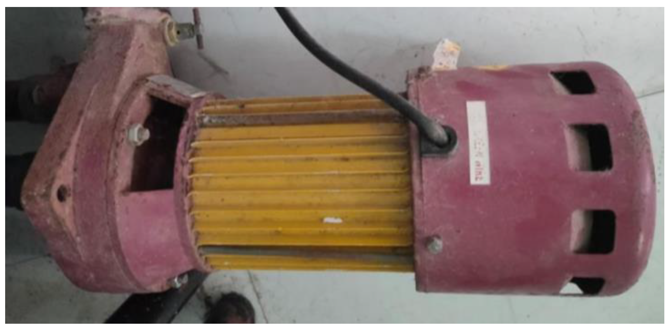
Energies 15 05183 g003
Figure 4. Motor used for research.
Energies 15 05183 g004
Figure 5. Motor (fan-cooled) drawn using Motor-CAD software (according to specifications of the chosen motor).
Energies 15 05183 g005
Figure 6. Water-cooled motor drawn using Motor-CAD.
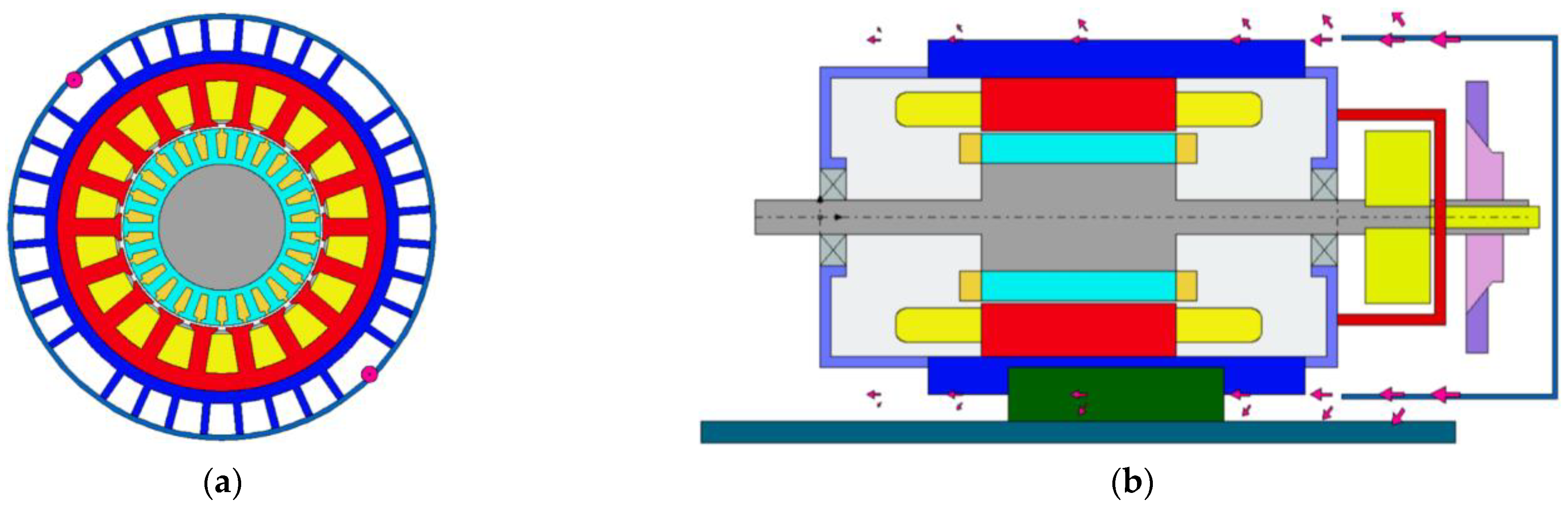
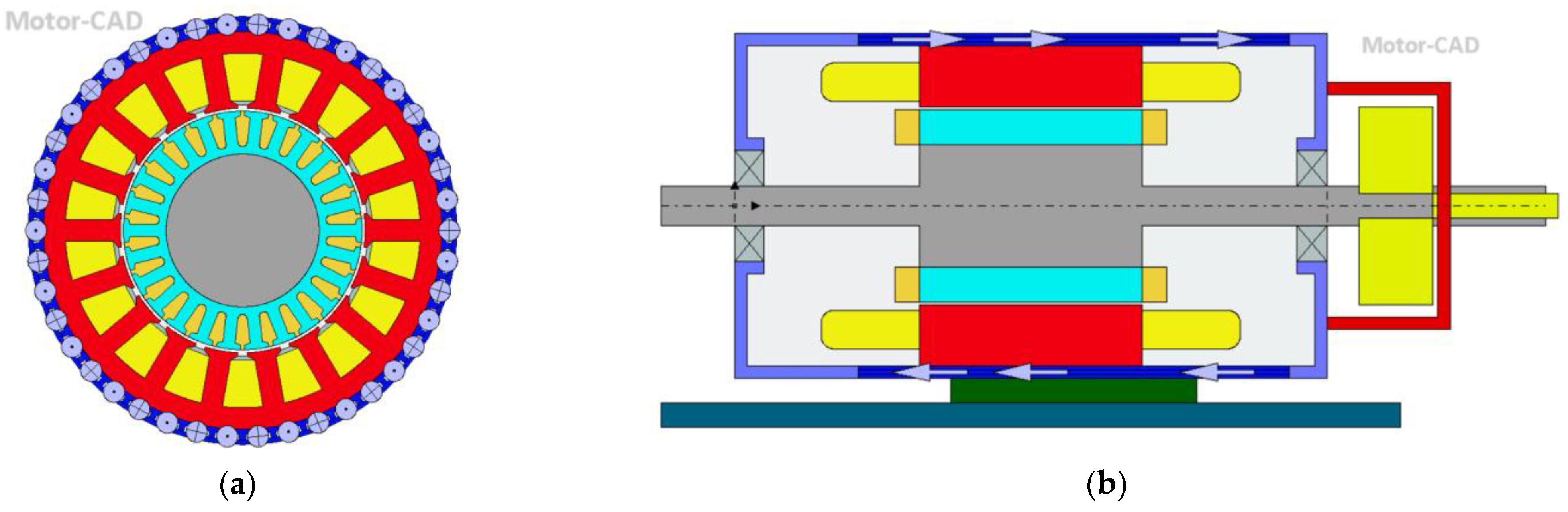
Energies 15 05183 g006
Figure 7. Radial view of fan-cooled motor mainly showcasing the housing type-axial fins (the windings, stator, and rotor) (a); axial view of fan-cooled motor depicting air flow coming from fan cooling system through the arrows (b).
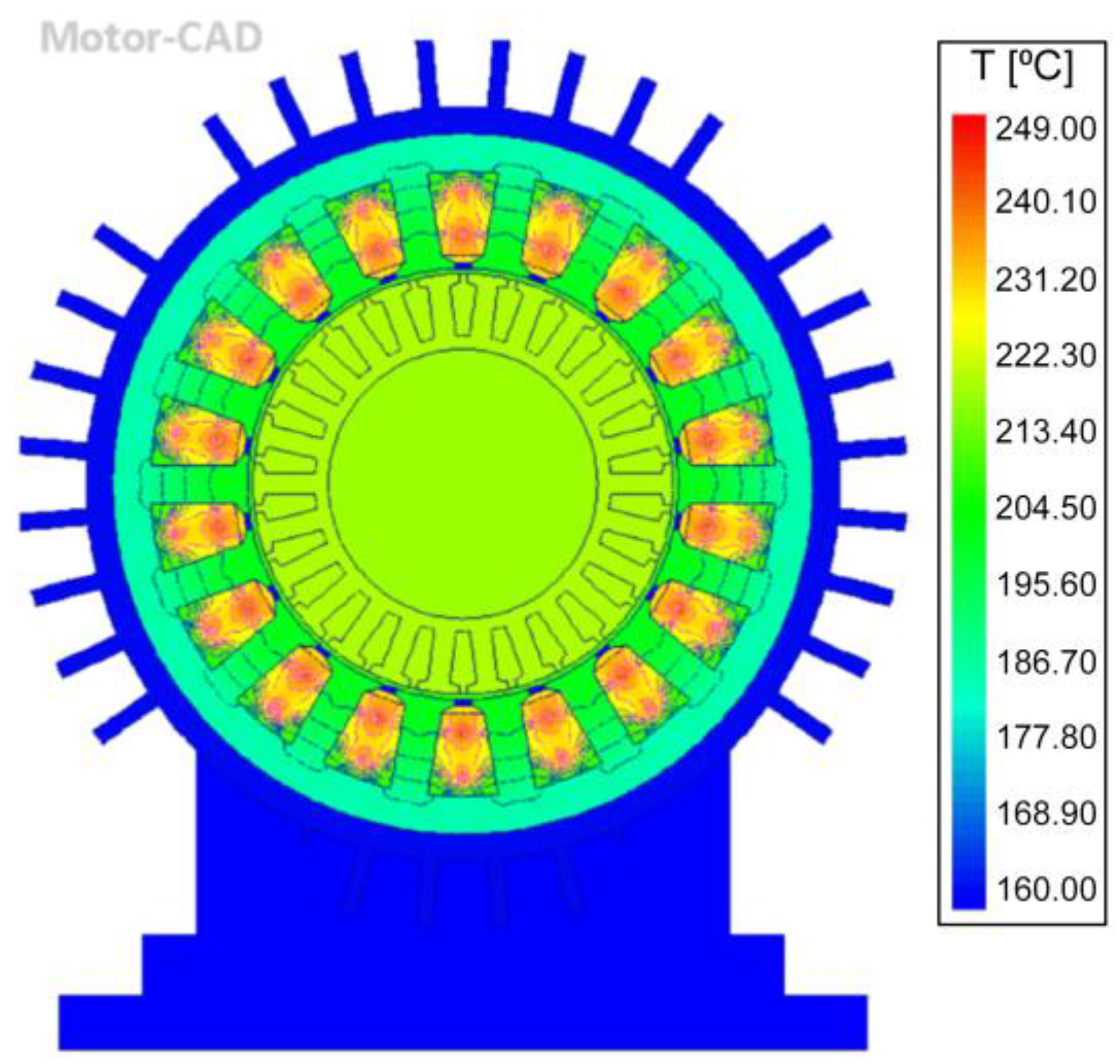
Energies 15 05183 g007
Figure 8. Radial view of motor (fan-cooled) after FEM analysis.
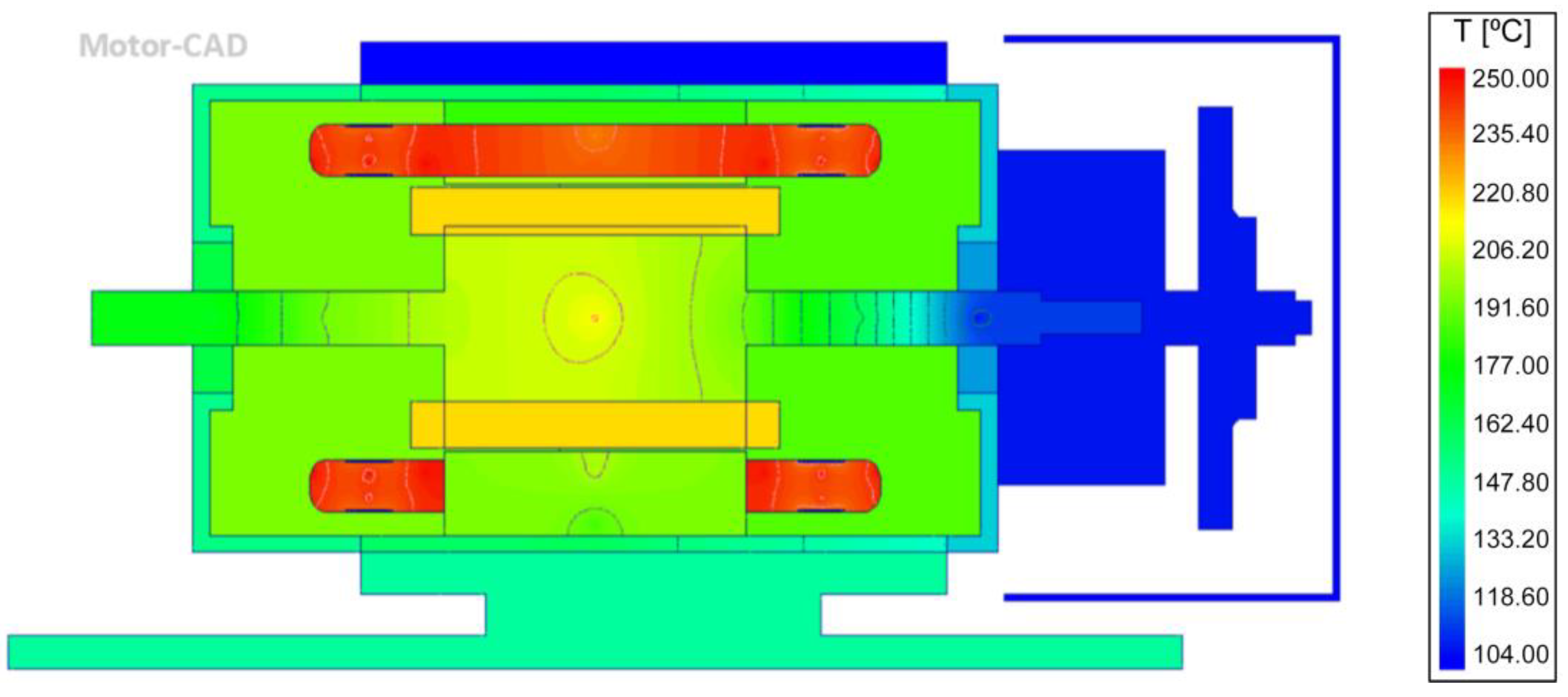
Energies 15 05183 g008
Figure 9. Axial view of motor (fan-cooled) after FEM analysis.
Energies 15 05183 g009
Figure 10. Radial view (a) and axial view (b) of water-cooled motor with aluminum casing (Alloy 195 cast) water-cooled motor.
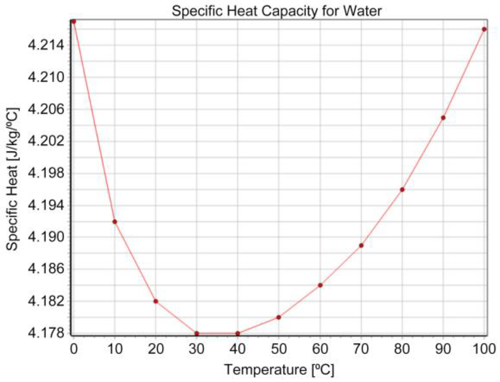
Energies 15 05183 g010
Figure 11. Specific heat capacity of water.
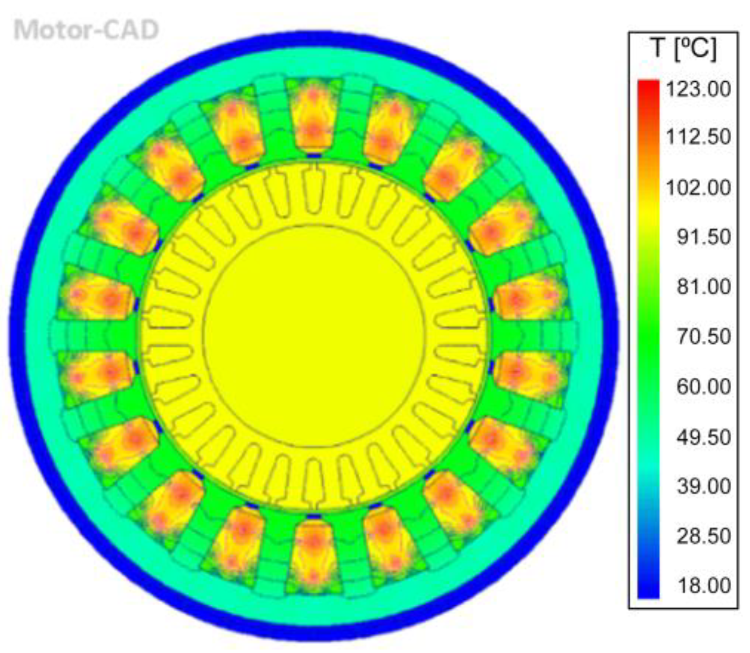
Energies 15 05183 g011
Figure 12. Radial view of water-cooled motor after FEM analysis.
Energies 15 05183 g012
Figure 13. Axial view of water-cooled motor (aluminum casing) after the FEM analysis.
Energies 15 05183 g013
Figure 14. Radial view of PA6GF30 casing electric motor (water-cooled after FEM analysis).
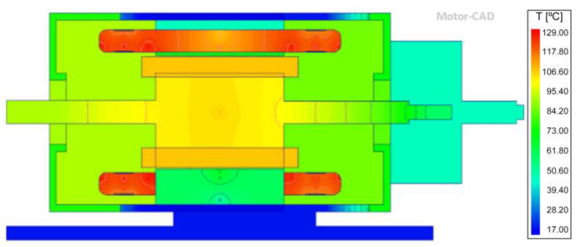
Energies 15 05183 g014
Figure 15. Axial view of water-cooled motor with PA6GF30 casing after FEM analysis.
Energies 15 05183 g015
Table 1. Motor dimensions.
Section/Part of the MotorSpecific PartDimensions (mm)
Radial dimensionsHousing diameter140
Stator lamination diameter130
Shaft diameter50
Shaft height95
Axial dimensionsMotor length240
Stator lamination length50
Rotor lamination length90
Base length350
Stator parametersHousing diameter140
Tooth width71
Fin extension12.5
Rotor parametersRotor bars26
Rotor tooth width4
Shaft diameter50
Table 2. Specifications of the single-phase induction motor.
ParametersValues
Rated output power373 W (0.5 HP)
Rated voltage230 V
Rated speed1430 rpm
Number of poles4
Number of stator slots24
Frequency50 Hz
TypePermanent split capacitor
Table 3. Comparison of properties between cast iron and CFRP.
Mechanical PropertiesCast IronCFRP
Tensile strength (ultimate)1650 MPa4000 MPa
Compressive stress1370 MPa890 MPa
Young’s modulus168 GPa500 GPa
Damping capacity11.5 × 10−311 × 10−3
Table 4. Lightweight materials comparison.
No.MaterialThermal Conductivity (k·m)Specific Heat
(g·K)
Density
(g/cm)
1.PA6GF300.411.301.36
2.Mg–Zn (magnesium alloy)1161.021.76
3.Ti–6Al–4V (titanium alloy)620.563.73
4.Epoxy carbon fiber52.021.21
Table 5. Input parameters for thermal analysis on fan-cooled motor (ANSYS Motor-CAD).
No.Input ParameterInput Data
1.HousingRound axial fins
2.Housing materialAluminum (alloy 195 cast), thermal conductivity—168 W/m/C, specific heat—833 J/kg/C
3.Armature winding materialCopper (pure), thermal conductivity—401 W/m/C, specific heat—385 J/kg/C
4.Calculation typeSteady-state thermal analysis
5.Input power800 W
6.Shaft speed2880 rpm
7.Cooling typeBlown over (convection) air cooling (TEFC)
8.Velocity of airReference flow velocity proportional to speed at 5 m/s
Table 6. Observations after FEM analysis on the air-cooled motor.
No.Output ParameterValue
1.Total weight of motor obtained including foot mounted base13 kg
2.Temperature range observed in radial thermal FEM analysis160–249 °C
3.Temperature range observed in axial thermal FEM analysis104–250 °C
Table 7. Comparison of thermal analyses of two fan-cooled motors from a previous study 28 and this study.
No.Comparison PartEEC Fan-Cooled Motor [28] (°C)Fan-Cooled Motor Used in This Study (°C)
1.Front cover91153.0
2.Rear bearing89125.2
3.Rear case84132.0
Table 8. Input parameters for thermal analysis on water-cooled motor with aluminum casing (ANSYS Motor-CAD).
No.Comparison PartFan-Cooled Induction Motor Used in This Study (°C)
1.HousingWater jacket (axial)
2.Housing materialAluminum (Alloy 195 cast), thermal conductivity—168 W/m/C, specific heat—833 J/kg/C
3.Armature winding materialCopper (pure), thermal conductivity—401 W/m/C, specific heat—385 J/kg/C)
4.Calculation typeSteady-state thermal analysis
5.Input power800 W
6.Shaft speed2880 rpm
7.Cooling typeHousing water jacket
8.Housing water jacket inlet temperature15 °C
9.Fluid properties7 L/min
10.Fluid volume flow rateFluid–water
Table 9. Fluid (coolant used) properties.
Fluid–Water
Thermal conductivity0.6167 W/m·K
Density994 kg/m3
Table 10. Observations for water-cooled motor with aluminum (Alloy 195 cast) casing.
No.Output ParameterValue
1.Total weight of motor obtained including foot mounted base12.1 kg
2.Temperature range observed in radial thermal FEA18–123 °C
3.Temperature range observed in axial thermal FEA17–124 °C
Table 11. Comparison of temperature analyses of two water-cooled motors from a previous study and this study.
No.Comparison PartWater-Cooled Motor [5] (°C)Water-Cooled Motor Used in This Study Set to Same Parameters as Study Motor in [5] (°C)
1.Casing temperature8465
2.Stator core temperature9880
Table 12. Axial temperatures for fan-cooled motor.
PartEndcapFrontOverhangCentralOverhangRearEndcap
Ambient 40 °C
Housing153.5 °C157.9 °C158. 6 °C160.2 °C145.2 °C140.5 °C132.2 °C
Stator (back iron) 184.0 °C
Stator surface 202.3 °C
Rotor surface 219.1 °C
Rotor tooth 219.3 °C
Rotor lamination 219.0 °C
Shaft164.3 °C170.1 °C193.7 °C217.3 °C164.7 °C104.68 °C125.23 °C
Rotor bar 218.9 °C219.3 °C218.3 °C
Blown over air 83.6 °C78.2 °C55.8 °C40 °C
Winding max. 252.9 °C248.3 °C252.8 °C
Winding av. 247.3 °C234.1 °C246.7 °C
Winding min. 232.2 °C195.7 °C233.8 °C
Table 13. Axial temperatures for water cooled motor (Alloy 195 casing).
PartEndcapFrontOverhangCentralOverhangRearEndcap
Ambient 40 °C
Housing32.5 °C20.0 °C17.5 °C18.1 °C17.1 °C21.8 °C26.1 °C
Stator (back iron) 45.7 °C
Stator surface 67.7 °C
Rotor surface 94.9 °C
Rotor tooth 95.2 °C
Rotor lamination 95.1 °C
Shaft48.0 °C60.5 °C76.3 °C94.2 °C74.1 °C55.7 °C42.9 °C
Rotor bar 94.7 °C95.2 °C94.6 °C
Winding max. 127.0 °C122.2 °C127.0 °C
Winding av. 120.8 °C105.2 °C120.8 °C
Winding min. 108.2 °C59.6 °C108.1 °C
Table 14. Input parameters for thermal analysis of water-cooled motor with PA6GF30 casing.
No.Input ParameterInput Data
1.HousingWater jacket (axial)
2.Housing materialPA6GF30, thermal conductivity—0.41 W/(K·m), specific heat—1.3 J/(g·K)
3.Armature winding materialCopper (pure), thermal conductivity—401 W/m/C, specific heat—385 J/kg/C)
4.Calculation typesteady-state thermal analysis
5.Input power800 W
6.Shaft speed2880 rpm
7.Cooling typeHousing water jacket
8.Housing water jacket inlet temperature15 °C
9.Fluid properties7 L/min
10.Fluid volume flow rateFluid–water
Table 15. Results of thermal analysis of water-cooled electric motor of lightweight PA6GF30 casing.
No.Output ParameterValue
1.Total weight of motor obtained including foot mounted base9.647 kg
2.Temperature range observed in radial thermal FEA18–126 °C
3.Temperature range observed in axial thermal FEA17–129 °C
Table 16. Axial temperature graph for water-cooled motor with PA6GF30 casing.
PartEndcapFrontOverhangCentralOverhangRearEndcap
Ambient 20 °C
Housing67.2 °C28.0 °C17.1 °C18.0 °C17.1 °C53.7 °C66.3 °C
Stator (back iron) 46.5 °C
Stator surface 69.4 °C
Rotor surface 104.8 °C
Rotor tooth 105.2 °C
Rotor lamination 105.1 °C
Shaft84.8 °C84.9 °C93.7 °C104.5 °C88.9 °C75.5 °C76.4 °C
Rotor bar 105.1 °C105.2 °C104.6 °C
Winding max. 131.0 °C125.2 °C130.3 °C
Winding av. 124.1 °C107.5 °C123.6 °C
Winding min. 113.6 °C60.6 °C112.3 °C
Table 17. Winding temperature graph for water-cooled motor with PA6GF30 casing.
PartCuboid 1Cuboid 2
End winding max.127.8 °C131.0 °C
End winding av.121.0 °C127.3 °C
End winding min.133.6 °C117.8 °C
Winding max.120.9 °C125.2 °C
Winding av.102.7 °C112.3 °C
Winding min.60.6 °C86.5 °C
End winding max.127.8 °C130.3 °C
End winding av.120.5 °C126.6 °C
End winding min.112.3 °C116.9 °C
Tooth58.5 °C68.7 °C
Table 18. Temperature reduction for Case-2 and Case-3 when compared to air-cooled motor (Case-1).
CasesLowest Temperature(along Axial Direction) (°C)Highest Temperature(along Axial Direction) (°C)Temperature Reduction of Highest Temperature When Compared to Air-Cooled Motor (%)
Case-1104250-
Case-21712450.4
Case-31712948.4
Table 19. Weight reduction for Case-2 and Case-3 when compared to air-cooled motor (Case-1).
ModelsWeight of the Motor (kg)Weight Reduction When Compared with Air-cooled Motor Model-1 (%)
Model-1 (air-cooled motor)13-
Model-2 (water-cooled withAlloy 195 casing)12.1-
Model-3 (water-cooled with PA6GF30)9.64720.27
Publisher’s Note: MDPI stays neutral with regard to jurisdictional claims in published maps and institutional affiliations.

