1. Introduction
Renewable energy will be the future as the push for energy decarbonization accelerates. These energy sources are virtually inexhaustible and replenish naturally. They also do not pollute the air or emit harmful greenhouse gases. The total renewable energy produced worldwide grew by more than 75% in the preceding decade, from 4196.94 to 7443.81 Terawatt-hours (TWh) [
1]. The International Energy Agency [
2] projects that renewable energy systems will account for almost 95% of the increase in the global power capacity over the next 5 years. Such accelerated growth is expected, with a more significant and concerted push towards net-zero emissions. By 2050, renewable energy systems will likely replace fossil fuel-based energy systems as the dominant energy source [
3,
4].
1.1. Current State and Prospects of Solar Energy Systems
Among all, harvesting solar energy is one of the fastest-growing avenues and most favored [
5]. Solar energy systems accounted for over half of all renewable power expansion in 2021 [
2]. It experienced the most growth in the preceding decade among all renewable energy systems. Its global output grew at a 38.8% compounded average growth rate, implying that annual solar power generation doubled every few years. If solar energy systems continued to grow at this rate, they would become the most significant contributor to power generation growth [
1,
2,
4,
6].
Solar energy is one of the safest forms of energy on Earth [
7]. Sunlight, the richest and most abundant resource that reaches all parts of Earth’s surface [
8], can be converted into electricity using photovoltaics, solar heating and cooling, and concentrating solar power [
9]. Photovoltaics (PVs), in particular, crystalline silicon PV modules (PVMs), are the most used instrument for harvesting solar energy today [
10]. If these modules are responsibly sited, harvesting solar energy is the cleanest method since it does not generate additional emissions [
9,
11]. Additionally, PVs can be combined into panels and arrays of different shapes and sizes for various applications. It can also be decentralized from the power grid and deployed on standalone applications such as solar rooftop panels and solar-powered cars. Collectively, these factors make PVs highly versatile, scalable, and attractive to the industries, research communities, and, especially, states with limited renewable energy options, such as Singapore [
12].
Heightened interest in PVs has exponentially improved their cost and performance since it was first commercially available. Today, the cost of PVs has fallen by more than a factor of 10,000 since its inception [
13]. In the preceding decade alone, the cost of PVs has fallen by about 90% [
14]. As PVs become an integral part of humanity’s net-zero plan, Henbest et al. [
15] estimate that for every year until 2030, we need to consistently install more than half of PVs’ cumulative capacity to date to achieve our net-zero emissions targets by the mid-century [
16]. Such accelerated adoption would further drive the unit cost of PVs down and potentially pave the way for it to become the least expensive alternative to obtaining renewable energy [
17,
18,
19].
1.2. Solar Photovoltaic Systems and the Circular Economy
As we anticipate an influx of PVMs to be deployed, we must remember that every physical product will eventually reach the end of its useful life. A PVM’s useful life is between 20 and 35 years [
10,
14,
20]. Hence, we expect an abundance of PVMs to reach the end of their useful life by 2050. Weckend et al. [
21] estimated that at least 8 million tons of PVMs will reach their end-of-life (EOL) annually, cumulating in 78 million tons by 2050. As the cost and performance of PVMs are expected to improve rapidly, Atasu et al. [
12] argue that rational customers will be incentivized to upgrade to cheaper and better models of PVMs continuously. This would result in widespread early replacements, pushing the estimated EOL PVM figures beyond 78 million tons by 2050.
Similar to the ubiquity of plastic in our ecosystem and its associated effects [
22], if EOL PVMs are not responsibly managed, it will result in pollution across our terrestrial ecosystem. This could indirectly encourage continuous mining and extraction of Earth’s finite resources and diminish the net environmental benefit of harvesting solar energy. Conversely, the successful recovery of EOL PVMs could reduce resource extraction and waste. It could further generate sufficient economic return and value to finance the production of another 2 billion PVMs by 2050 [
10,
14,
23]. Therefore, EOL PVMs must be adequately managed and encouraged to participate in the circular economy.
Today, industry actors are actively searching for effective and responsible circular strategies. Our review aims to accelerate their efforts and contribute to formulating their strategies by informing them of the critical sustainability aspects of a solar PV system. Our approach differs but synergistically complements and builds upon existing life cycle assessment-based (LCA-based) contributions, where the environmental impacts of solar PV systems are quantitatively evaluated in well-defined system boundaries and parameters. Instead, we comprehensively review the state of the sustainability knowledge of a solar PV system, across its critical structural components and life cycle, before synthesizing and presenting its most significant insights. Primarily, our article focuses on silicon-based PV systems and their EOL as they accounted for 95% of the global PV production in 2020 [
24].
First, the article succinctly introduces a typical PVM design. Then, it extensively discusses the current EOL PVM recovery methods. A section is dedicated to recovering embedded metals in the EOL PVM and the current state-of-the-art end-to-end EOL PVM recovery processes. Finally, several interrelated observations from this review that impede or accelerate efforts to achieve an effective and responsible circular strategy for solar PV systems are extensively discussed.
2. Design of a Photovoltaic Module
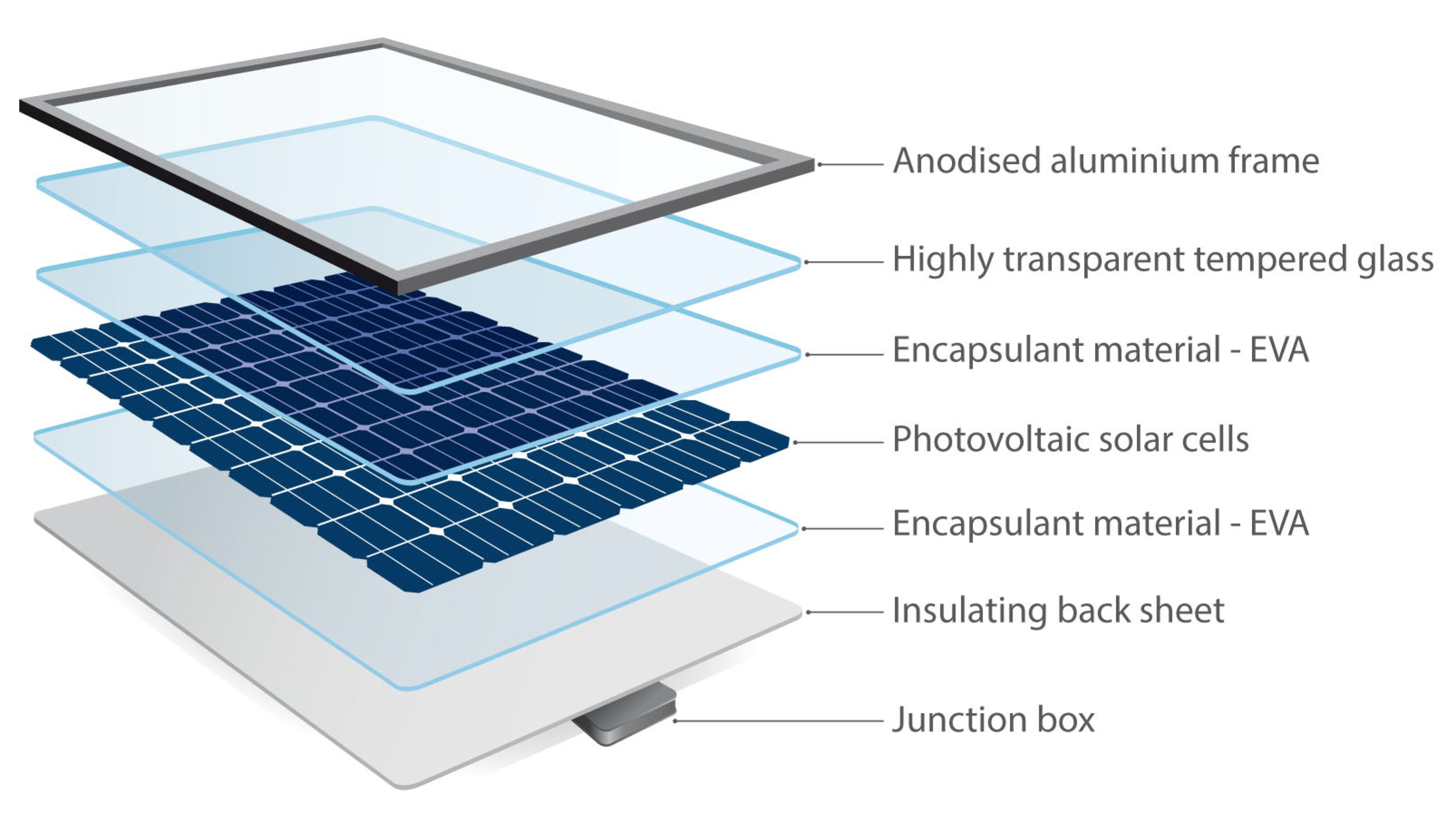
Figure 1 illustrates the principal components of a silicon-based PVM [
25,
26]. At the same time,
Table 1 lists its materials and their corresponding mass, expressed as a percentage of the total.
By weight, the actual PV cell is less than 5% of the entire PVM [
27,
28]. As PVMs are deployed outdoors, they must be built to withstand changing and potentially harsh weather conditions. For this reason, PV cells are sandwiched between layers of glass sheets and flexible polymer encapsulants before being mounted onto an aluminum frame [
29]. This protects the cells from external interferences and allows them to achieve optimal performance. Inside the PVM, other elements such as silver, copper, lead, and tin are embedded for various functional reasons [
30]. Including silicon, these materials are scarce and valuable. Hence, they should ideally be recovered and recycled into new applications [
31]. However, a contemporary PVM design involves many compacted and interconnected materials, making their separation challenging.
Further, these components must be delicately extracted without damage to preserve the intrinsic value and purity of the materials recovered. Our review suggests that pretreatment of the EOL PVM is the key to maximizing its value and quantity recovery. The treatment of EOL PVM methods includes physical, chemical, and a combination of both [
32,
33,
34].
3. Recovery Methods for End-of-Life Photovoltaic Modules
3.1. Physical Methods
3.1.1. Mechanical Method
The mechanical recovery method starts with manually dismantling and removing the junction box and aluminum frame from the EOL PVM. After disassembly, the remainder is crushed and sorted by its physical properties [
35]. After crushing, the ethylene-vinyl acetate (EVA) particles are sieved using a vibratory separator at low temperatures [
36]. Physical separation typically concludes after the EVA particles are sieved. While no adverse environmental effects arise from physically taking the EOL PVM apart, the first mechanical recovery stage produces low-purity recyclates that need further sorting into their elements.
Additional separation steps may include flotation, electrostatic separation, eddy current separation, and mechanical screening [
37]. The flotation method separates each substance by density, producing crushed glass sizes between 45 and 850 µm [
38]. In comparison, electrostatic separation separates each substance by its electrical conductivity and properties [
39]. The recyclates can be segregated into conductors (e.g., metals), semiconductors (e.g., silicon powder), and insulators through electrostatic action. A practical drawback of electrostatic separation is that glass is often separated into conductors alongside metals. Thus, electrostatic separation remains ineffective and needs further improvement before enjoying widespread adoption.
On the other hand, the eddy current separation method uses an electric vortex separator to separate the crushed recyclates. The elements are separated by their conductivity and shape [
40]. The magnetic drum in the electric vortex spins at high speed to create an alternating magnetic field, creating an eddy current in the conductive metal as it passes through the field. The two opposing magnetic fields create a repulsive force (Lorentz) that separates the metal from the crushed recyclates. The recyclates’ particle size must be optimized for this process to dissociate metals from the EVA remnants effectively.
Lastly, the mechanical screening method screens and sorts the recyclates by size, shape, thickness, and other differences. This method achieves more than an 85% recovery rate for silicon despite the inherent difficulty of separating the crushed recyclates mechanically. Correspondingly, the mechanical screening method is preferred as it is practical, requires the least energy, and requires no chemical reagents.
Recently, scholars have investigated the effectiveness of high-voltage pulse crushing, which has a higher selectivity than traditional mechanical crushing methods. High-voltage pulse crushing separates copper, aluminum, lead, silver, and tin [
41,
42]. As components in the EOL PVM have different dielectric constants, conductive channels among components are formed and respond to an electrical breakdown in a high-voltage discharge. During an electrical breakdown, large amounts of high-temperature and high-pressure plasma expand the channels, leading to the selective separation of each component [
38]. A higher voltage (>100 kV) and pulse frequency are needed for high-voltage pulse crushing to be effective. However, the modern-day environment does not allow these conditions to be met, resulting in limited applications.
3.1.2. Pyrolysis
Pyrolysis, or heat treatment, is another physical EOL PVM recovery method. EOL PVMs are placed in furnaces with elevated temperatures above 400 °C to obtain clean PV cells [
43]. At the same time, the EVA film, backplane—often Tedlar Polyester Tedlar (TPT) based—and other organic matters are decomposed, leaving the remnants of the aluminum frame, tempered glass, and PV cells. Unlike the mechanical recovery method, there is no crushing involved. Hence, the glass and PV cell remnants remain intact and can be recycled as it is [
44]. Hydrometallurgy is then used to remove the metal electrodes and impurities from the remnant PV cells to acquire high-purity silicon (99.999%) [
45].
As pyrolysis aims to decompose EVA films thermally, many studies have focused on its processes, products, and related mechanism. Scholars have observed no correlation between the heating rates and the weight of EVA films. Therefore, this suggests that EVA films can only be removed at an optimized temperature. The EVA removal process involves deacetylation (organic intermediate formation) and long-chain fracture with free radical reaction (hydrocarbon formation). The former mainly produces acetic acid and a small amount of acetaldehyde by deacetylation. Then, the latter carbonizes and degrades the organic intermediate to form the hydrocarbon. Recent investigations have also found that by combining nitrogen pyrolysis and vacuum decomposition, targeted hydrocarbon (such as linear alkenes, alkanes, and their isomers) could be recovered at a 100% organic conversion rate as the EVA decomposes [
46].
Overall, pyrolysis efficiently separates glasses, PV cells, and backplanes. It is also a relatively simple treatment process. However, it is energy-intensive and requires high-specification equipment to operate. Furthermore, its by-products may adversely impact the environment and business viability. For example, heat-treating EVA in an oxidizing atmosphere may lead to the oxidization of silicon-based cells, which affects the quality of the silicon recovered.
Additionally, heat-treating EVA film and TPT backplane at a high temperature can produce a large amount of organic matter that pollutes the environment. Therefore, future studies using pyrolysis for EOL PVMs must focus on its industrial-scale viability and environmental aspects. It must also account for current trends, including the ongoing transition toward thinner polysilicon wafers—from 550 to 180 µm—which scholars speculate would increase the wafer’s risk of breaking during pyrolysis [
47].
3.2. Chemical Methods
Compared with the physical treatment methods, chemical treatment methods are relatively simple and consume less energy. Inorganic and organic solvent dissolution are both chemical treatment methods.
3.2.1. Inorganic Solvent Dissolution
The inorganic solvent dissolution method requires the EOL PVM to be immersed in an acid or alkali solution. Immersion dissolves the EVA film, leaving behind the PV cell sheet. Nitric acid and hydrofluoric acid are commonly used solvents. The process removes metal impurities and the silicon nitride anti-reflective layer (ARL) on the cell’s surface to recover metal electrodes and high-purity silicon. Two methods have been developed to remove metal impurities from the cell’s surface [
47].
The first is a pure-acid method. First, phosphoric acid removes the aluminum electrode and silicon nitride ARL. Next, nitric acid and hydrofluoric acid mixture are applied to remove silver and other metal impurities from the cell’s surface. Lee et al. [
48] found that a mixed acid solution of nitric acid and hydrofluoric acid at a ratio of 83:17 can efficiently reclaim cleaned high-performing silicon wafers.
The second method uses both acid and alkali. Nitric acid and hydrofluoric acid mixture are applied to remove the silicon nitride ARL and the silver electrode. Following this, sodium hydroxide is used to remove the aluminum electrode. The drawback of this method is that it produces grooves on the surface of the silicon wafers, which unfavorably affects its performance for future applications. Additionally, as nitric acid is not adept at penetrating the EOL PVM, removal of the EVA film using this method is much slower. However, studies suggest that exposing nitric acid to higher temperatures could remove the EVA film faster. For instance, Klugmann-Radziemska and Ostrowski [
45] reported that heating nitric acid to 40 °C during the dissolution process is critical to splitting each major EOL PVM component apart to extract the silicon wafer. In addition to increasing the temperature of nitric acid, scholars have explored various workarounds. Their proposed alternatives have primarily centered on nitric acid, potassium hydroxide, and phosphoric acid to remove all unwanted components to extract the silicon wafer. Regardless of the chosen route, the obtained silicon wafers via both acid and alkali are reported to be of satisfactory quality to recreate lead-free PVMs with a comparable conversion efficiency to those made from new silicon wafers [
47,
49].
Overall, while the inorganic solvent dissolution method is a fast and straightforward process with low energy consumption and high efficiency, the successful extraction of all valuable metals for recycling is not guaranteed. Additionally, as hydrofluoric acid is highly toxic and corrosive, the by-products from this process can pollute the environment. Similarly, nitric oxide and nitrogen dioxide are also aftereffects of this process; thus, equipment is needed to treat the tail gas.
3.2.2. Organic Solvent Dissolution
The EVA film expands and dissolves while being soaked in different organic solvents. While soaked, the various components are exposed and separated, allowing the PV cell sheet to be extracted. The expansion and dissolution reactions correspond to the crosslinked and non-crosslinked parts of the EVA films. The expansion process widens the gap between the tempered glass and the silicon panel while the dissolution process dissolves the EVA film into liquid. Studies have noted that EVA’s fluidity in organic reagents increases as the reaction temperature increases. Other studies have noted that the dissolvent could easily overcome EVA’s adhesive properties, thus allowing the EOL PVM to be separated and recycled [
50].
Additionally, by comparing how the EVA film swells in different organic solvents, studies have suggested that the glass and silicon PV cells can be separated from the rest of the EOL PVM after two days of soaking [
51]. As this method is relatively slower, Kim and Lee [
50] developed an ultrasonic-assisted organic solvent method to accelerate the dissolution of EVA films. With their process, the EVA films could be wholly dissolved in o-dichlorobenzene within 30 min at 70 °C and 900 W irradiation power to recover PV cells in good condition.
Successful recovery of the EOL PVM depends on whether the EVA film can be thoroughly removed without implicating the rest of the valuable components. The organic solvent method is effective in this scenario as it only targets and treats the EVA film. However, its effectiveness depends on how tightly bonded and sticky each layer of PVM is. The tighter and stickier the layers are, the harder it is for the organic solvent to diffuse, penetrate, and react accordingly. Apart from its slow dissolution rate, it is worth noting that most organic solvents are toxic, volatile, expensive, and difficult to dispose of after use, affecting their feasibility for large-scale EOL PVM recycling efforts.
3.3. Physical-Chemical Method
As discussed earlier, both the physical and chemical methods have merits and drawbacks. Their primary limitations are their degree of separation and recovery. For example, the physical method is not adept at thoroughly separating the EOL PVM into its elemental components, while the chemical method is only effective at removing EVA films. Hence, the physical-chemical method was developed to take advantage of the merits while leaving the drawbacks behind.
Generally, the mechanical recovery methods (
Section 3.1.1) are first used to pre-treat the EOL PVM. This process crushes and splits the EOL PVM into fragments between 0.08 and 0.4 mm. These tiny fragments cause the embedded EVA film to lose its adhesiveness. It also negates EVA’s influence on metal leaching [
52], thus paving the way for the fragments to be directly soaked in an acid leaching reagent consisting of nitric acid, sulfuric acid, and hydrogen peroxide at 60 °C. Glass will not be dissolved during this process and can be recovered directly [
53]. In contrast, valuable metals are recovered with hydrometallurgical techniques [
54]. As the EOL PVM has been pre-treated, the amount of chemical reagents needed for hydrometallurgy is significantly reduced.
As the mix of physical and chemical methods is increasingly accepted and adopted in contemporary environments, scholars have continuously worked with the industry to refine the method’s efficiency. For example, Klugmann-Radziemska et al. [
55] used the pyrolysis and chemical dissolution methods to recover clean silicon wafers from EOL PVM. Their process pre-treats and separates the cell sheet, backplane, cover glass, and aluminum frame using heat before using chemical reagents to remove the ARL and electrode coating on the surface of the cell sheet. On the other hand, Kang et al. [
56] used organic solvents to isolate and recover the glasses before using pyrolysis to remove the EVA film and obtain the silicon. The recovered silicon was then chemically etched to remove all the metallic impurities on its surface to obtain 99.999% high-purity silicon. Tao and Yu [
57] also noted that some industry actors used pyrolysis to remove plastics in the EOL PVM before manually separating the remaining remnants. They reported that this process, etching, and other further treatments could recover up to 84% of the EOL PVM. Additionally, they reported that the heat from the incinerator could be recycled for other processes, including preheating.
While most works have focused on refining the process, other scholarly works have focused on the interactions between the materials and the processes. For example, Pagnanelli et al. [
58] attempted to understand and prescribe the optimal treatment methods based on the size of the crushed EOL PVM recyclates. They reported that recyclates with 0.4- and 1.0-mm particle sizes could be directly recycled. In contrast, recyclates with a particle size greater than 1.0 mm needed to be treated by pyrolysis to separate the EVA film and glass. For tiny recyclates (particle size smaller than 0.4 mm), chemical methods were prescribed to dissolve the metals and recycle the glass. They reported that 90% of the EOL PVM can be recovered by categorizing and treating the recyclates by size.
All in all, the physical-chemical method has a high waste utilization and recovery rate. When optimized, it can increase the specific surface area of metals, shorten their leaching time, and reduce chemical reagents’ use. Hence, we feel the industry will be steered towards using a mixed physical-chemical method to treat EOL PVM. However, as researchers actively investigate and accelerate industrial adoption of physical-chemical methods, one must be aware of its drawbacks. Presently, mechanically crushing the silicon cell into silicon powder increases the area of contact with air, leading to higher levels of silicon oxidation. Hence, a more potent reducing agent and more energy are needed to mitigate this issue in subsequent extractions. Additionally, D’Adamo et al. [
59] noted the current state of the art as complex, energy-intensive, and generating waste liquids. Therefore, we believe a viable and widely accepted solution must be simple and energy-efficient.
Table 2 outlines the key advantages and disadvantages of the earlier discussed EOL PVM recovery methods.
4. Recovery of Metals in End-of-Life Photovoltaic Modules
PVMs contain valuable metals. These metals must be recovered and reconditioned for future uses to participate in the circular economy upon reaching their EOL. These metals include silver and scattered metals.
4.1. Silver
Most studies suggest nitric acid is critical in recovering silver from EOL PVMs [
60]. For example, Simon et al. [
61] extracted silver powder using a multi-step process that involves dissolving nitric acid, precipitating silver chloride, co-heating sodium hydroxide, and hydrazine hydrate reduction. After extracting the silver powder, he used electrolytic refining techniques to obtain 99.99% pure silver. The EOL PVM must be pre-treated before the process to attain its desired outcomes. It needs to be crushed into recyclates of less than 0.5 mm. The fragments are then etched with nitric acid, allowing the silver particles to be precipitated and form silver chloride in the subsequent stages [
52]. Other studies also demonstrated the possibility of attaining a 100% leaching recovery of silver by utilizing the nitric acid leaching reagents under optimal leaching conditions [
62].
To reduce environmental pollution from the extraction of silver, Yousef et al. [
63] proposed milling the EOL PVM to destroy the chemical bonds between the metal electrode and silicon layer before using nitric acid with a 60% or higher concentration to leach out silver. Following this, they proposed using a microfiltration process to extract the silicon particles and purify them with hydrofluoric acid etching to remove silicon nitride contamination. Lastly, centrifugation was proposed to separate the aluminum nanocrystals from the leached solution before adding hydrochloric acid to recover silver chloride from the remaining saturated solution.
4.2. Scattered Metals
Compound semiconductor solar cells such as gallium arsenide (GaAs) [
64], cadmium telluride (CdTe) [
65], indium phosphide (InP), and copper indium gallium selenide (CIGS) [
66] are emerging alternatives to silicon-based PV cells. These emerging alternatives use scattered metals such as indium, tellurium, gallium, and selenium as their base material. Scattered metals are classified as critical metals and are limited in quantity. Given the current landscape, scattered metals will likely face material supply constraints when their global installed capacity exceeds a terawatt [
67]. Hence, ensuring these emerging alternatives participate in the circular economy is crucial to developing and scaling next-generation solar energy systems. The means to recover them from their EOL PVMs include acid leaching, solvent extraction, and vacuum distillation.
4.2.1. Acid Leaching
The acid leaching method uses inorganic acid to leach the scattered metals from CIGS PV cells and CdTe PV cells. As metals and other oxides in the acid have excellent solubility, the metal ions can be transferred to the acid leaching solution, allowing coarse metals to be obtained after follow-up treatments (solvent extraction, replacement precipitation, and resin separation) [
68]. Commonly used acid leaching solutions include concentrated forms of hydrochloric acid, sulfuric acid, nitric acid, and other mixed acids.
Table 3 outlines the leaching effects of different acid leaching systems.
Hydrochloric acid has the best leaching effect in a single acid leaching liquid system. However, it is volatile and generates chlorine in the reaction process. Nitric acid is also volatile and more expensive than hydrochloric and sulfuric acid. Additionally, it is highly oxidizing and prone to toxic nitrogen oxides. Comparatively, sulfuric acid is relatively cheaper and more accessible. Sulfuric acid has a higher boiling point. Hence, while its leaching and dissolution rates can be accelerated with a higher leaching temperature, its leaching efficiency remains relatively low. Therefore, hydrogen peroxide is often added to sulfuric acid to improve its leaching rate and overcome this issue. Presently, this mixed solution is the most widely used metal leaching agent. During the acid leaching process, its leaching rate can be further improved with other auxiliary means (such as ultrasonic) and other oxidants (such as hydrogen peroxide and manganese dioxide).
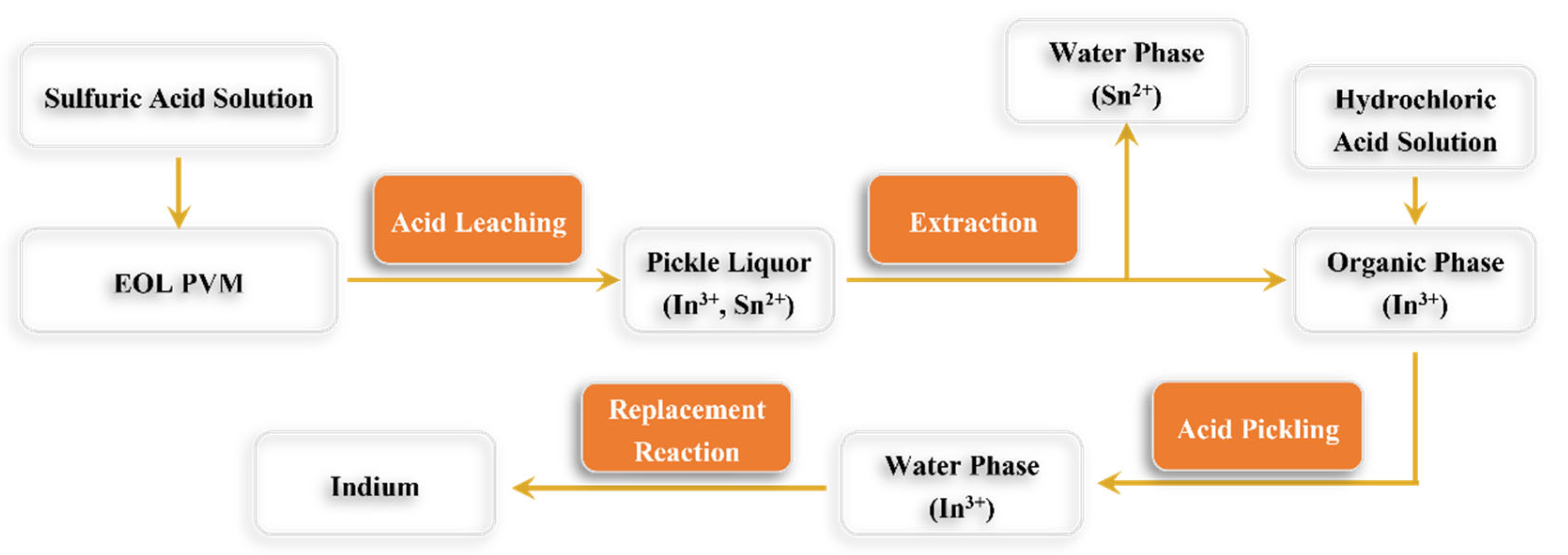
Acid leaching is the most used method to recover indium from indium-containing waste. By optimizing the properties of the leaching solution and conditions, Fang et al. [
74] recovered 92.42% of the indium from indium-containing waste.
Figure 2 illustrates how indium can be extracted using the acid leaching process.
Aside from leaching indium, the acid leaching method can also leach telluride and cadmium [
75]. Studies have demonstrated that more than 67% of telluride can be recovered from CdTe PV cells when sulfuric acid and hydrogen peroxide are used to leach. With optimization, the highest recovery efficiency for telluride and cadmium exceeds 80% and 99%, respectively. While more than 99% of cadmium can be recovered with acid leaching, the remainder is waste solutions that must be treated with suitable water recycling treatment technologies. Presently, different acid leaching pathways for CdTe EOL PVMs have been developed. However, each has drawbacks that need to be addressed before industry adoption. For example, while CdTe EOL PVMs can be leached with iron (III) chloride or hydrogen chloride, telluride could probably not be separated from iron [
71].
Another example is leaching CdTe EOL PVMs with sulfuric acid or hydrogen peroxide. While it demonstrated a better separation efficiency, a sizeable proportion (about 4% to 7%) of the total residue contains cadmium, telluride, and sulfur [
76]. The process is also relatively expensive due to high voltage and temperature requirements, making it unattractive for industrialization. Lastly, CdTe EOL PVMs can also be leached with nitric acid. Doing so recovers 96% pure telluride while cadmium is left behind. Additionally, highly concentrated nitric acid requires a high-temperature environment of 60 to 80 °C to work, inevitably producing nitrate smoke [
77].
Overall, the merits of using acid leaching lie with its mild reaction conditions and easy control of the reaction process. On the flip side, this method has complicated reaction steps, is time-consuming, and requires a large amount of acid. Furthermore, due to various impurities in the waste acid, the acid leaching liquid needs to be purified to a certain standard before being recycled or discharged.
4.2.2. Solvent Extraction
Solvent extraction typically uses an organic or mixed organic solvent. It is used to form the coordination compound with the metal ions and facilitate its transfer to other organic solvents, thereby achieving the separation and purification of metal ions. Solvent extraction methods are simple, efficient, and low-cost. It also has a large production capacity and can attain high-purity products. As such, these methods are widely used in refining scattered metals.
The literature suggests that different solvent extraction agents are needed for different metal ions. It is not an all-encompassing solution. For example, the common solvent extraction agents for extracting Te include neutral and nitrogen extraction agents, mercaptan, alcohol, and naphthenic acid [
78]. On the other hand, phosphorus oxide—in particular, Di-(2-Ethylhexyl) phosphoric acid (D2EHPA)—is the most used acidic phosphorus extraction agent to extract indium due to its good chemical stability, high extraction efficiency, and low cost. As for extracting selenium and gallium, studies have suggested using hydrochloric acid and sulfuric acid systems as the most efficient agents.
Overall, our review indicates that the organic extraction method is a simple and efficient recovery process capable of obtaining high-purity products. However, it is expensive, and the methods may adversely implicate our environment and biological systems. Therefore, future developments for this method must address these concerns.
5. End-of-Life Photovoltaic Module Recovery Process
5.1. Full Recovery End-of-Life Photovoltaics (FRELP)
The first process focused on maximizing material recovery from EOL PVMs. This concept was first mooted by the European Union (EU). In 2012, the EU changed its Waste Electrical and Electronic Equipment (WEEE) Directive to include PVMs [
79]. With this enactment, all PVMs were effectively banned from being landfilled and mandated to be recycled. At this time, there were limited means to recycle PVMs effectively and responsibly. Therefore, the EU funded research efforts to address this gap to ensure policy effectiveness and stakeholder compliance. Their efforts cumulated in the Full Recovery End of Life Photovoltaics (FRELP) project, which attempted to create a process to recover as many functional components from EOL PVMs as possible [
80].
Ideally, the FRELP project partners aspired to achieve an economically viable method to recover 100% of EOL PVMs [
81]. Based on the latest publicly available information, the FRELP project is in the pilot-scale stage, with a facility capable of treating roughly 1300 PVMs daily. However, the plant has stopped operating due to the insufficient and inconsistent volume of EOL PVMs arriving at its facility [
10].
The FRELP process follows a four-phase physical-chemical treatment method [
82]. In each phase, selected components are recovered through their appropriate means. For example, aluminum and connectors are recovered using mechanical detachment systems in the first phase. In the subsequent phases, acid, pyrolysis, and electrolysis are applied to recover silicon and other metals [
29]. Recent reports have suggested that the FRELP process can recover more than 95% of glass, aluminum, silicon, and copper from EOL PVMs [
80]. It can also recover 94% of silver but not tin or lead [
10]. Compared to merely removing the aluminum frame and cables and shredding the rest, the FRELP process results in a 10% to 15% overall improvement in impact categories such as global warming potential, ozone depletion, and ecotoxicity [
80].
However, the FRELP process is not perfect. While waste from EOL PVMs has been drastically reduced, it is not eliminated. For every ton of EOL PVMs that underwent the FRELP process, there will be close to 30 kg of residues that are landfilled or lost [
80]. Additionally, the quality of silicon and metals recovered through the FRELP process is deemed inferior. As a result, this diminishes its economic value and makes it unsuitable for reuse in new PVMs. To this extent, experts estimated a return of only USD 3 on each PVM recovered through the FRELP process, which is less than its per-unit cost of recovery [
29]. This means that loss is incurred in every unit of EOL PVMs recovered through the FRELP process. With poor unit economics, EOL PVM recycling through the FRELP process will not take off.
5.2. Arizona State University (ASU) Method
For EOL PVM recycling to take off, it must be a commercially viable and profitable pursuit. Recognizing this proposition, a team at the Arizona State University proposed a different strategy to recover EOL PVMs. Instead of maximizing the mass of materials recovered, they proposed strategies to maximize the value of materials recovered. Dubbed the ASU method, this process is estimated to produce a return of USD 13 on each EOL PVM recovered [
29] without leaving much behind for landfilling. At USD 13 revenue per unit, this recovery model is suitable for private facilities to operate profitably without relying on state support [
20].
The ASU method is also a multi-step process that uses physical-chemical treatment methods. It involves sequential electrowinning, using a heated nitric acid solution to extract and recover multiple metals from the highly compacted and interconnected PV cell. Following this, a secondary process called sheet resistance monitoring is applied to recover solar-grade silicon. While the ASU method does not recover the maximum mass, its process can recover metals of 99% purity and silicon that meet the standard for the solar grade. It can also recover silver, the most valuable solar material component, at 99% purity [
29]. This explains the significant difference in the recovered material value between the FRELP and ASU methods.
As the ASU method is a recent discovery, its drawbacks and feasibility of operating sustainably at an industrial scale have yet to be thoroughly investigated. Nonetheless, even at a laboratory scale, where the conditions and feedstock are controlled, the ASU team has successfully demonstrated the technical and financial possibility of EOL PVMs being responsibly and effectively recovered.
6. Discussion
Our review arrived at three interrelated observations. Firstly, we observed that most works aimed at advancing EOL PVM recovery have meticulously focused on improving specific technical performances of an existing method (physical, chemical, or mixed). This singularly focused approach often led scholars to pay little to no attention to other critical aspects of their developments, such as their environmental sustainability performance. For example, while the physical-chemical method achieves a high waste utilization and recovery rate, it is energy-intensive and produces waste liquids that need further treatment. Similarly, while the inorganic solvent dissolution method is a fast and straightforward process, it produces harmful by-products that, if leaked, will have significant adverse implications. Even when these methods are integrated into a process and optimized for maximum material recovery, the FRELP process still produces an average of 3% residues that require further treatment.
For these reasons, we encourage scholars to utilize assessment tools, such as the life cycle assessment (LCA), to holistically assess and report the environmental sustainability performance of their developments in addition to the technical improvements. While it is unrealistic to expect a method to achieve zero sustainability compromises, at the very least, scholars should always strive to develop and propose solutions with a net environmental benefit. We posit that these sustainability compromises are inevitable unless the PVM design synergistically aligns and complements its recovery methods. Unfortunately, the recovery methods are retrospectively applied today. Such methods make it difficult to efficiently extract high-purity recyclates from EOL PVMs without producing additional waste and carbon emissions. The lesson learned is that planning for the EOL of the next-generation PVMs should not be an afterthought. Hence, taking a step further, we encourage scholars to explore the development of tools and frameworks to enable next-generation PVMs to be designed for participation in the circular economy.
Our second observation relates to the scale of published works. We observed that most works were conducted at a laboratory scale or trialed on a small scale. We speculate that scholars might have limited opportunities to conduct large-scale investigations due to the global lack of established PVM recovery facilities to collaborate. Similar to the discontinuation of the FRELP project, the insufficient and inconsistent volume of EOL PVMs could be the primary reason behind the lack of industrial-scale facilities. Nevertheless, we believe this problem is transient and will gradually be resolved when annual EOL PVM generation exceeds 130,000 tons, the estimated level by the “European Association for the Recovery of PV Modules” required for PVM recovery activities to be sustainable [
83]. In the meantime, the lack of access to realistic field tests remains a severe limitation to advancing further research. Without empirical data and evidence, it is difficult for scholars to continuously improve and propose readily adoptable solutions. Nevertheless, scholars should creatively devise means to conduct realistic simulations and prepare for upcoming field testing opportunities.
By extension of our second observation, our third observation relates to unit economics. Today’s unit economic calculations for EOL PVM recovery processes are primarily estimated and may not accurately represent future operations. Hence, similar to testing and reporting the technical and sustainability performances of the proposed solutions, the unit economics must be critically evaluated in a representative operational environment. More importantly, the unit economics must be financially attractive for industry players to participate. Presently, economic incentives for recovering EOL PVMs are severely limited as there is much uncertainty about the dominant recovery process, related investments required, and profitability. We believe that deriving representative unit economics will be an emerging research area that directly affects the future direction of EOL PVM recovery research.
In sum, for future works to add significant value, scholars must consider how their proposed solutions can be integrated into a more extensive industrial-scale system. At the same time, they must also consider its overall sustainability, operational feasibility, and economic viability. We recommend that scholars adopt tools such as LCA and techno-economic assessment to evaluate their technologies’ environmental and economic aspects thoroughly. We firmly believe harmonizing these aspects is critical for any solution to scale beyond laboratory scale and achieve widespread adoption. Scholars should also lead the way in redesigning PVMs with their EOL in mind if given the opportunity.
7. Conclusions
In conclusion, we discussed the urgent need for energy decarbonization and how it accelerates the world’s transition to adopting renewable energy sources. Solar energy is highly favored and widely adopted. Silicon-based PVMs, the most used instrument to capture and convert solar energy to electricity today, will continue to be rapidly deployed.
As all PVMs will eventually reach their end of life, this will create an abundance of incoming EOL PVMs. We discussed the consequences of mismanagement of EOL PVMs. This can result in (a) pollution across our terrestrial ecosystem, (b) indirectly encourage continuous mining and extraction of Earth’s finite resources, and (c) diminish the net environmental benefit of harvesting solar energy. On the other hand, the successful recovery of EOL PVMs could reduce resource extraction and waste and generate sufficient economic return and value to finance the production of another 2 billion PVMs by 2050.
Despite several proposed EOL PVM recovery methods (physical, chemical, and mixed) and processes (FRELP and ASU), none seemed to be a proven, effective, and responsible industrial-scale solution to manage the incoming EOL PVMs and reclaim their valuable materials. While the current state-of-the-art demonstrated the technical and financial possibility of EOL PVMs being responsibly and effectively recovered, more needs to be done to ensure the desired outcome can be achieved at an industrial scale. To this end, accessing realistic field testing opportunities is critical for scholars to evaluate the practicality and implications of their proposals. Other critical variables such as its overall sustainability, operational feasibility, and economic viability must also be considered. Regardless, our review firmly suggests that scholars, the industry, and relevant stakeholders have recognized the imperative for EOL PVMs to participate in the circular economy. They also agree that ineffective EOL PVM management will become a black eye for the supposedly clean industry.
Author Contributions
J.T.: Conceptualization, methodology, formal analysis, investigation, resources, writing—original and revision draft preparations, S.J.: Conceptualization, methodology, formal analysis, investigation, resources, writing—original draft, S.R.: Resources, supervision. All authors have read and agreed to the published version of the manuscript.
Funding
This research received no external funding.
Institutional Review Board Statement
Not applicable.
Informed Consent Statement
Not applicable.
Data Availability Statement
Data is contained within the article.
Acknowledgments
J.T. would like to acknowledge the support provided by the NUS Research Scholarship (GRSUR5000001 Res Sch (PhD) SERIS SC) during his study.
Conflicts of Interest
The authors declare no conflict of interest.
Abbreviations
The following abbreviations are used in this manuscript:
| ARL | Anti-Reflective Layer |
| ASU | Arizona State University |
| CdTe | Cadmium Telluride |
| CIGS | Copper Indium Gallium Selenide |
| EOL | End-of-Life |
| EU | European Union |
| EVA | Ethylene-Vinyl Acetate |
| FRELP | Full Recovery End of Life Photovoltaics |
| GaAs | Gallium Arsenide |
| InP | Indium Phosphide |
| LCA | Life Cycle Assessment |
| PV | Photovoltaics |
| PVM | Photovoltaics Modules |
| TPT | Tedlar Polyester Tedlar |
| TWh | Terawatt-hours |
| WEEE | Waste Electrical and Electronic Equipment |
References
- BP. Statistical Review of World Energy 2021, 70th Edition; BP p.l.c.: London, UK, 2021; p. 70. [Google Scholar]
- International Energy Agency (IEA). Renewables 2021: Analysis and forecast to 2026; International Energy Agency: Paris, France, 2021. [Google Scholar]
- Dale, S. Energy Outlook 2020 Edition. BP p.l.c.: London, UK, 2020. [Google Scholar]
- McKinsey & Company. Global Energy Perspective 2021; McKinsey & Company: Atlanta, GA, USA, 2021; p. 9. [Google Scholar]
- Sundaram, S.; Benson, D.; Mallick, T.K. Overview of the PV Industry and Different Technologies. In Solar Photovoltaic Technology Production; Elsevier: Amsterdam, The Netherlands, 2016; pp. 7–22. [Google Scholar]
- Christophe Ballif, F.-J.H.; Boccard, M.; Verlinden, P.J.; Hahn, G. Status and perspectives of crystalline silicon photovoltaics in research and industry. Nat. Reviews. Mater. 2022. [Google Scholar] [CrossRef]
- Desjardins, J. The Safest Source of Energy Will Surprise You. Available online: https://elements.visualcapitalist.com/worlds-safest-source-energy/ (accessed on 10 December 2021).
- Kabir, E.; Kumar, P.; Kumar, S.; Adelodun, A.A.; Kim, K.-H. Solar energy: Potential and future prospects. Renew. Sustain. Energy Rev. 2018, 82, 894–900. [Google Scholar] [CrossRef]
- Solar Energy Industries Association. Solar Energy. Available online: https://www.seia.org/initiatives/about-solar-energy (accessed on 4 August 2021).
- Heath, G.A.; Silverman, T.J.; Kempe, M.; Deceglie, M.; Ravikumar, D.; Remo, T.; Cui, H.; Sinha, P.; Libby, C.; Shaw, S.; et al. Research and development priorities for silicon photovoltaic module recycling to support a circular economy. Nat. Energy 2020, 5, 502–510. [Google Scholar] [CrossRef]
- Sundaram, S.; Benson, D.; Mallick, T.K. Potential Environmental Impacts From Solar Energy Technologies. In Solar Photovoltaic Technology Production; Elsevier: Amsterdam, The Netherlands, 2016; pp. 23–45. [Google Scholar]
- National Climate Change Secretariat. Singapore’s Approach To Alternative Energy. Available online: https://www.nccs.gov.sg/singapores-climate-action/singapore-approach-to-alternative-energy/ (accessed on 16 February 2021).
- Nemet, G.F. How Solar Energy Became Cheap: A Model for Low-Carbon Innovation; Routledge: London, UK, 2019. [Google Scholar] [CrossRef]
- Atasu, A.; Duran, S.; Wassenhove, L.V. The Hidden Cost of Solar Energy. Available online: https://knowledge.insead.edu/responsibility/the-hidden-cost-of-solar-energy-17926 (accessed on 20 February 2021).
- Henbest, S.; Kimmel, M.; Callens, J.; Vasdev, A.; Brandily, T.; Berryman, I.; Danial, J.; Vickers, B. New Energy Outlook 2021; BloombergNEF: London, UK, 2021. [Google Scholar]
- BloombergNEF. New Energy Outlook 2021. Available online: https://about.bnef.com/new-energy-outlook/ (accessed on 15 August 2021).
- Tan, J.; Cha, V. Innovation for Circular Economy. In An Introduction to Circular Economy; Springer: Singapore, 2021; pp. 369–395. [Google Scholar]
- BP. Wind and Solar Power Grow Rapidly. Available online: https://www.bp.com/en/global/corporate/energy-economics/energy-outlook/renewable-energy.html (accessed on 15 March 2021).
- Phadke, A.; Paliwal, U.; Abhyankar, N.; McNair, T.; Paulos, B.; Wooley, D.; O’Connell, R. 2035 The Report-Electricity; University of California, Berkeley: Berkeley, CA, USA, 2021; p. 37. [Google Scholar]
- Huang, W.-H.; Shin, W.J.; Wang, L.; Sun, W.-C.; Tao, M. Strategy and technology to recycle wafer-silicon solar modules. Solar Energy 2017, 144, 22–31. [Google Scholar] [CrossRef] [Green Version]
- Weckend, S.; Wade, A.; Heath, G. End-of-Life Management: Solar Photovoltaic Panels; International Renewable Energy Agency (IRENA): Abu Dhabi, United Arab Emirates, 2016. [Google Scholar]
- Tan, J.; Tiwari, S.K.; Ramakrishna, S. Single-Use Plastics in the Food Services Industry: Can It Be Sustainable? Mater. Circ. Econ. 2021, 3, 7. [Google Scholar] [CrossRef]
- Tan, J.; Tan, F.J.; Ramakrishna, S. Transitioning to a Circular Economy: A Systematic Review of Its Drivers and Barriers. Sustainability 2022, 14, 1757. [Google Scholar] [CrossRef]
- Fraunhofer Institute for Solar Energy Systems. Photovoltaics Report; Fraunhofer Institute for Solar Energy Systems, ISE: Freiburg im Breisgau, Germany, 2022. [Google Scholar]
- Rao, H.K.R.; Gemechu, E.; Thakur, U.; Shankar, K.; Kumar, A. Life cycle assessment of high-performance monocrystalline titanium dioxide nanorod-based perovskite solar cells. Sol Energy Mater. Sol. Cells 2021, 230, 10. [Google Scholar] [CrossRef]
- Duflou, J.R.; Peeters, J.R.; Altamirano, D.; Bracquene, E.; Dewulf, W. Demanufacturing photovoltaic panels: Comparison of end-of-life treatment strategies for improved resource recovery. Cirp Ann.-Manuf. Technol. 2018, 67, 29–32. [Google Scholar] [CrossRef]
- Latunussa, C.E.L.; Ardente, F.; Blengini, G.A.; Mancini, L. Life Cycle Assessment of an innovative recycling process for crystalline silicon photovoltaic panels. Sol. Energy Mater. Sol. Cells 2016, 156, 101–111. [Google Scholar] [CrossRef]
- Ardente, F.; Blengini, G.; Mancini, L.; Latunussa, C.; Pennington, D. Analysis of Material Recovery from Photovoltaic Panels; European Commission, Joint Research Centre: Ispra, Italy, 2016. [Google Scholar]
- Bomgardner, M.M.; Scott, A. Recycling Renewables. Available online: https://cen.acs.org/energy/renewables/Recycling-renewables/96/i15 (accessed on 25 March 2022).
- Mathur, N.; Singh, S.; Sutherland, J.W. Promoting a circular economy in the solar photovoltaic industry using life cycle symbiosis. Resour. Conserv. Recycl. 2020, 155, 104649. [Google Scholar] [CrossRef]
- Huang, B.J.; Zhao, J.; Chai, J.Y.; Xue, B.; Zhao, F.; Wang, X.Y. Environmental influence assessment of China’s multi-crystalline silicon (multi-Si) photovoltaic modules considering recycling process. Sol. Energy 2017, 143, 132–141. [Google Scholar] [CrossRef]
- Jung, B.; Park, J.; Seo, D.; Park, N. Sustainable System for Raw-Metal Recovery from Crystalline Silicon Solar Panels: From Noble-Metal Extraction to Lead Removal. ACS Sustain. Chem. Eng. 2016, 4, 4079–4083. [Google Scholar] [CrossRef]
- Tokoro, C.; Lim, S.; Sawamura, Y.; Kondo, M.; Mochidzuki, K.; Koita, T.; Namihira, T.; Kikuchi, Y. Copper/Silver Recovery from Photovoltaic Panel Sheet by Electrical Dismantling Method. Int. J. Autom. Technol. 2020, 14, 966–974. [Google Scholar] [CrossRef]
- Zhang, Z.; Liu, M.; Wang, L.; Chen, T.P.; Zhao, L.; Hu, Y.F.; Xu, C.J. Optimization of indium recovery from waste crystalline silicon heterojunction solar cells by acid Leaching. Sol. Energy Mater. Sol. Cells 2021, 230, 8. [Google Scholar] [CrossRef]
- Granata, G.; Pagnanelli, F.; Moscardini, E.; Havlik, T.; Toro, L. Recycling of photovoltaic panels by physical operations. Sol. Energy Mater. Sol. Cells 2014, 123, 239–248. [Google Scholar] [CrossRef]
- Zhang, J.; Lv, F.; Ma, L.Y.; Yang, L.J. The status and trends of crystalline silicon PV module recycling treatment methods in Europe and China. Adv. Mater. Res. 2013, 724, 200–204. [Google Scholar] [CrossRef]
- Salama, A.; Richard, G.; Medles, K.; Zeghloul, T.; Dascalescu, L. Distinct recovery of copper and aluminum from waste electric wires using a roll-type electrostatic separator. Waste Manag. 2018, 76, 207–216. [Google Scholar] [CrossRef]
- Akimoto, Y.; Iizuka, A.; Shibata, E. High-voltage pulse crushing and physical separation of polycrystalline silicon photovoltaic panels. Miner. Eng. 2018, 125, 1–9. [Google Scholar] [CrossRef]
- Dias, P.; Schmidt, L.; Gomes, L.B.; Bettanin, A.; Veit, H.; Bernardes, A.M. Recycling Waste Crystalline Silicon Photovoltaic Modules by Electrostatic Separation. J. Sustain. Metall. 2018, 4, 176–186. [Google Scholar] [CrossRef]
- Smith, Y.R.; Nagel, J.R.; Rajamani, R.K. Electrodynamic Eddy Current Separation of End-of-Life PV Materials. In Proceedings of the Energy Technologies Symposium, San Diego, CA, USA, 26 February–2 March 2017; pp. 379–386. [Google Scholar]
- Song, B.-P.; Zhang, M.-Y.; Fan, Y.; Jiang, L.; Kang, J.; Gou, T.-T.; Zhang, C.-L.; Yang, N.; Zhang, G.-J.; Zhou, X. Recycling experimental investigation on end of life photovoltaic panels by application of high voltage fragmentation. Waste Manag. 2020, 101, 180–187. [Google Scholar] [CrossRef]
- Nevala, S.-M.; Hamuyuni, J.; Junnila, T.; Sirviö, T.; Eisert, S.; Wilson, B.P.; Serna-Guerrero, R.; Lundström, M. Electro-hydraulic fragmentation vs conventional crushing of photovoltaic panels–Impact on recycling. Waste Manag. 2019, 87, 43–50. [Google Scholar] [CrossRef] [PubMed]
- Wang, R.X.; Song, E.X.; Zhang, C.L.; Zhuang, X.N.; Ma, E.; Bai, J.F.; Yuan, W.Y.; Wang, J.W. Pyrolysis-based separation mechanism for waste crystalline silicon photovoltaic modules by a two-stage heating treatment. RSC Adv. 2019, 9, 18115–18123. [Google Scholar] [CrossRef] [PubMed] [Green Version]
- Bogust, P.; Smith, Y.R. Physical Separation and Beneficiation of End-of-Life Photovoltaic Panel Materials: Utilizing Temperature Swings and Particle Shape. JOM 2020, 72, 2615–2623. [Google Scholar] [CrossRef]
- Klugmann-Radziemska, E.; Ostrowski, P. Chemical treatment of crystalline silicon solar cells as a method of recovering pure silicon from photovoltaic modules. Renew. Energy 2010, 35, 1751–1759. [Google Scholar] [CrossRef]
- Zhang, L.G.; Xu, Z.M. Separating and Recycling Plastic, Glass, and Gallium from Waste Solar Cell Modules by Nitrogen Pyrolysis and Vacuum Decomposition. Environ. Sci. Technol. 2016, 50, 9242–9250. [Google Scholar] [CrossRef]
- Shin, J.; Park, J.; Park, N. A method to recycle silicon wafer from end-of-life photovoltaic module and solar panels by using recycled silicon wafers. Sol. Energy Mater. Sol. Cells 2017, 162, 1–6. [Google Scholar] [CrossRef]
- Lee, J.-K.; Lee, J.-S.; Ahn, Y.-S.; Kang, G.-H.; Song, H.-E.; Lee, J.-I.; Kang, M.-G.; Cho, C.-H. Photovoltaic performance of c-Si wafer reclaimed from end-of-life solar cell using various mixing ratios of HF and HNO3. Sol. Energy Mater. Sol. Cells 2017, 160, 301–306. [Google Scholar] [CrossRef]
- Park, J.; Park, N. Wet etching processes for recycling crystalline silicon solar cells from end-of-life photovoltaic modules. RSC Adv. 2014, 4, 34823–34829. [Google Scholar] [CrossRef]
- Kim, Y.; Lee, J. Dissolution of ethylene vinyl acetate in crystalline silicon PV modules using ultrasonic irradiation and organic solvent. Sol. Energy Mater. Sol. Cells 2012, 98, 317–322. [Google Scholar] [CrossRef]
- Doi, T.; Tsuda, I.; Unagida, H.; Murata, A.; Sakuta, K.; Kurokawa, K. Experimental study on PV module recycling with organic solvent method. Sol. Energy Mater. Sol. Cells 2001, 67, 397–403. [Google Scholar] [CrossRef]
- Dias, P.; Javimczik, S.; Benevit, M.; Veit, H.; Bernardes, A.M. Recycling WEEE: Extraction and concentration of silver from waste crystalline silicon photovoltaic modules. Waste Manag. 2016, 57, 220–225. [Google Scholar] [CrossRef] [PubMed]
- Riech, I.; Castro-Montalvo, C.; Wittersheim, L.; Giácoman-Vallejos, G.; González-Sánchez, A.; Gamboa-Loira, C.; Acosta, M.; Méndez-Gamboa, J. Experimental Methodology for the Separation Materials in the Recycling Process of Silicon Photovoltaic Panels. Materials 2021, 14, 581. [Google Scholar] [CrossRef] [PubMed]
- Dias, P.R.; Benevit, M.G.; Veit, H.M. Photovoltaic solar panels of crystalline silicon: Characterization and separation. Waste Manag. Res. 2016, 34, 235–245. [Google Scholar] [CrossRef] [PubMed]
- Klugmann-Radziemska, E.; Ostrowski, P.; Drabczyk, K.; Panek, P.; Szkodo, M. Experimental validation of crystalline silicon solar cells recycling by thermal and chemical methods. Sol. Energy Mater. Sol. Cells 2010, 94, 2275–2282. [Google Scholar] [CrossRef]
- Kang, S.; Yoo, S.; Lee, J.; Boo, B.; Ryu, H. Experimental investigations for recycling of silicon and glass from waste photovoltaic modules. Renew. Energy 2012, 47, 152–159. [Google Scholar] [CrossRef]
- Tao, J.; Yu, S.R. Review on feasible recycling pathways and technologies of solar photovoltaic modules. Sol. Energy Mater. Sol. Cells 2015, 141, 108–124. [Google Scholar] [CrossRef]
- Pagnanelli, F.; Moscardini, E.; Granata, G.; Abo Atia, T.; Altimari, P.; Havlik, T.; Toro, L. Physical and chemical treatment of end of life panels: An integrated automatic approach viable for different photovoltaic technologies. Waste Manag. 2017, 59, 422–431. [Google Scholar] [CrossRef]
- D’Adamo, I.; Miliacca, M.; Rosa, P. Economic Feasibility for Recycling of Waste Crystalline Silicon Photovoltaic Modules. Int. J. Photoenergy 2017, 2017, 6. [Google Scholar] [CrossRef]
- Yan, Y.; Wang, Z.; Wang, D.; Cao, J.W.; Ma, W.H.; Wei, K.X.; Yun, L. Recovery of Silicon via Using KOH-Ethanol Solution by Separating Different Layers of End-of-Life PV Modules. JOM 2020, 72, 2624–2632. [Google Scholar] [CrossRef]
- Simon, F.G.; Holm, O.; Berger, W. Resource recovery from urban stock, the example of cadmium and tellurium from thin film module recycling. Waste Manag. 2013, 33, 942–947. [Google Scholar] [CrossRef]
- Lee, C.H.; Hung, C.E.; Tsai, S.L.; Popuri, S.R.; Liao, C.H. Resource recovery of scrap silicon solar battery cell. Waste Manag. Res. 2013, 31, 518–524. [Google Scholar] [CrossRef] [PubMed]
- Yousef, S.; Tatariants, M.; Tichonovas, M.; Makarevicius, V. Sustainable technology for mass production of Ag nanoparticles and Al microparticles from damaged solar cell wafers. Waste Manag. 2019, 98, 126–134. [Google Scholar] [CrossRef] [PubMed]
- Yu, M.; Li, Y.Q.; Cheng, Q.J.; Li, S. Numerical simulation of graphene/GaAs heterojunction solar cells. Sol. Energy 2019, 182, 453–461. [Google Scholar] [CrossRef]
- Dingus, P.; Garnett, J.; Wang, S.M.; Chong, C. Low cost single crystal CdZnTe-Silicon tandem PV. Renew. Energy 2021, 168, 659–667. [Google Scholar] [CrossRef]
- Ramanujam, J.; Bishop, D.M.; Todorov, T.K.; Gunawan, O.; Rath, J.; Nekovei, R.; Artegiani, E.; Romeo, A. Flexible CIGS, CdTe and a-Si:H based thin film solar cells: A review. Prog. Mater. Sci. 2020, 110, 20. [Google Scholar] [CrossRef]
- Grandell, L.; Höök, M. Assessing Rare Metal Availability Challenges for Solar Energy Technologies. Sustainability 2015, 7, 11818–11837. [Google Scholar] [CrossRef] [Green Version]
- Li, Y.H.; Liu, Z.H.; Li, Q.H.; Liu, Z.Y.; Zeng, L. Recovery of indium from used indium-tin oxide (ITO) targets. Hydrometallurgy 2011, 105, 207–212. [Google Scholar] [CrossRef]
- Gabriel, A.P.; Kasper, A.C.; Veit, H.M. Acid leaching of indium from the screens of obsolete LCD monitors. J. Environ. Chem. Eng. 2020, 8, 6. [Google Scholar] [CrossRef]
- Cao, Y.; Li, F.; Li, G.M.; Huang, J.W.; Zhu, H.C.; He, W.Z. Leaching and purification of indium from waste liquid crystal display panel after hydrothermal pretreatment: Optimum conditions determination and kinetic analysis. Waste Manag. 2020, 102, 635–644. [Google Scholar] [CrossRef]
- Tolley, W.K.; Swarup, R. Recovering Cadmium And Tellurium From Thin-Film Photovoltaic Device Scrap. In Proceedings of the EPD Congress 1995, at the Annual Meeting of the Minerals-Metals-and-Materials-Society, Las Vegas, NV, USA, 12–16 February 1995; pp. 503–510. [Google Scholar]
- Song, Q.M.; Zhang, L.G.; Xu, Z.M. Indium recovery from In-Sn-Cu-Al mixed system of waste liquid crystal display panels via acid leaching and two-step electrodeposition. J. Hazard Mater. 2020, 381, 8. [Google Scholar] [CrossRef]
- Dhiman, S.; Gupta, B. Cyphos IL 104 assisted extraction of indium and recycling of indium, tin and zinc from discarded LCD screen. Sep. Purif. Technol. 2020, 237, 12. [Google Scholar] [CrossRef]
- Fang, S.; Tao, T.Y.; Cao, H.B.; Zheng, X.H.; Hu, Y.Y.; Zhang, Y.; Sun, Z. Selective Recovery of Gallium (Indium) from Metal Organic Chemical Vapor Deposition Dust-A Sustainable Process. ACS Sustain. Chem. Eng. 2019, 7, 9646–9654. [Google Scholar] [CrossRef]
- Haddout, A.; Raidou, A.; Fahoume, M. Influence of the layer parameters on the performance of the CdTe solar cells. Optoelectron. Lett. 2018, 14, 6. [Google Scholar] [CrossRef]
- Rocchetti, L.; Beolchini, F. Recovery of valuable materials from end-of-life thin-film photovoltaic panels: Environmental impact assessment of different management options. J. Clean. Prod. 2015, 89, 59–64. [Google Scholar] [CrossRef]
- Kuczynska-Lazewska, A.; Klugmann-Radziemska, E.; Witkowska, A. Recovery of Valuable Materials and Methods for Their Management When Recycling Thin-Film CdTe Photovoltaic Modules. Materials 2021, 14, 10. [Google Scholar] [CrossRef]
- Chen, W.-S.; Chen, Y.-J.; Yueh, K.-C.; Cheng, C.-P.; Chang, T.-C. Recovery of valuable metal from Photovoltaic solar cells through extraction. IOP Conf. Ser. Mater. Sci. Eng. 2020, 720, 012007. [Google Scholar] [CrossRef]
- European Commission. Waste from Electrical and Electronic Equipment (WEEE). Available online: https://ec.europa.eu/environment/topics/waste-and-recycling/waste-electrical-and-electronic-equipment-weee_en (accessed on 25 March 2022).
- Latunussa, C.; Mancini, L.; Blengini, G.; Ardente, F.; Pennington, D. Analysis of Material Recovery from Silicon Photovoltaic Panels; European Union: Luxembourg, 2016. [Google Scholar]
- FRELP Project. Objectives. Available online: https://frelp.info/the-project/objective/ (accessed on 25 March 2021).
- FRELP Project. Activities. Available online: https://frelp.info/the-project/activities/ (accessed on 25 March 2021).
- Yi, Y.K.; Kim, H.S.; Tran, T.; Hong, S.K.; Kim, M.J. Recovering valuable metals from recycled photovoltaic modules. J. Air Waste Manag. Assoc. 2014, 64, 797–807. [Google Scholar] [CrossRef]
| Publisher’s Note: MDPI stays neutral with regard to jurisdictional claims in published maps and institutional affiliations. |
© 2022 by the authors. Licensee MDPI, Basel, Switzerland. This article is an open access article distributed under the terms and conditions of the Creative Commons Attribution (CC BY) license (https://creativecommons.org/licenses/by/4.0/).


