Article

An nth Harmonic Current Suppression Method Based on the Impulse Current PWM Technique for a Multi-Phase Permanent Magnet Synchronous Motor Fed with a Current Source Inverter

School of Automation, Beijing Institute of Technology, Beijing 100081, China
*
Author to whom correspondence should be addressed.
Energies 2022, 15(12), 4394; https://doi.org/10.3390/en15124394
Submission received: 13 May 2022 / Revised: 9 June 2022 / Accepted: 14 June 2022 / Published: 16 June 2022

Abstract

:
Among the existing harmonic current suppression methods, it is difficult and complicated to suppress any nth harmonic current accurately for multi-phase permanent magnet synchronous motors (PMSMs). To solve this problem, this paper takes a five-phase dual-rotor PMSM fed with a current source inverter (CSI) as an example, and proposes an nth harmonic current suppression method based on the impulse current PWM algorithm. Firstly, the analysis is conducted and presented for the nth harmonic current in the mth harmonic space. Then, based on the Sliding Discrete Fourier Transformation (SDFT), a low-pass filter (LPF) named SDFT-LPF is designed. Additionally, the impulse current PWM technique for the five-phase CSI is realized. In this paper, the experiments have confirmed that the SDFT-LPF has good filter performance. Compared with the SVPWM, the impulse current PWM technique has the same DC-link current utilization rate, but it is easier to implement. Moreover, the proposed harmonic current control method can accurately control any nth harmonic current without changing the PWM technique, which has significantly reduced the complexity of the harmonic current control. Additionally, the proposed scheme is easy to implement and can be directly extended to the multiple harmonic current’s control.

1. Introduction

Due to its inherent fault-tolerant capability and low torque ripple [1,2], the multi-phase permanent magnet synchronous motor (PMSM) is suitable for mission-critical applications, such as the off-shore ship propulsion, and electric vehicles [3,4]. However, since the back electromotive force (EMF) of the multi-phase PMSM is usually not the ideal sinusoidal wave, the motors contain many harmonic currents, which decrease the operation performance of the motor. Consequently, many studies have been reported to eliminate the harmonic currents.
According to Ohm’s law, motor currents are produced by the voltage applied to the resistance between the inverter output and EMF. Then, based on this, harmonic currents can be controlled by eliminating the proper harmonics of the inverter output. The existing harmonic current suppression methods can be divided into hardware-based and control-based. In general, some harmonic currents can be eliminated by applying the filter to inverter, which is easy to implement. However, in high-power applications, the filter has a large volume and is not flexible enough. Unlike the filter, the output waveform can also be more sinusoidal by increasing the levels of the inverter [5,6]. The common topologies of a multilevel inverter have a flying capacitor, neutral point clamped and cascaded H-bridge [7]. For a multilevel inverter, the modulation using a higher-sided polygonal space vector structure (SVS) is an elegant method to eliminate the undesired lower-order harmonics. Therefore, some SVSs have been proposed, such as dense 15-concentric 30-sided multilevel SVS [8] and 117-concenric 30-sided SVS [9].
Compared with the filter and multilevel inverter, the control-based harmonic elimination methods do not need additional hardware, resulting in wide applications. According to the Fourier Series, the periodic waveform can be decomposed into a series of sinusoidal waveforms. For pulse width modulation (PWM) inverters, the output is a series of pulses with equal amplitudes and unequal widths. Based on this, the selected harmonic elimination PWM (SHEPWM) is proposed, which can eliminate the low-order harmonics with low switching frequency. However, it has a high computation burden and large memory consumption. To simplify the calculation of the switching angles, Luis David Pabon Fernandez optimized it using genetic algorithms [10]. Additionally, the Newton–Raphson method, resultant theory, particle swarm optimization, and colonial competitive algorithm have also been reported. However, all these methods can only work offline and save the angles in a memory. Thus, some analytical techniques for SHEPWM for real-time implementation have been proposed [11,12].
Unlike the SHEPWM, the harmonic components can also be suppressed by turning the synthesizing vector to zero in the corresponding harmonic plane according to the space vector theory. Based on this theory, some harmonic current suppression methods have been proposed, such as field-oriented control (FOC)-based, direct torque control (DTC)-based, and model predictive control (MPC)-based methods. To suppress the third harmonic voltage, Fei Yu adopted the nearest four vectors’ space vector pulse width modulation (SVPWM) [13]. In the over-modulation region, it is difficult to eliminate the low-order harmonics with a low carrier frequency. To solve this problem, R. Sudharshan Kaarthik adopted the dodecagonal SVS and proposed a simple PWM timing calculation method [14]. To find the best method to apply a time sequence in a switching pattern, Mohammad Bayati Booin optimized the process with three vectors by using the genetic algorithm [15].
DTC has many advantages, such as good transient performance and a simple structure. A combination of large and medium vectors is utilized in [16] to make the average volt–seconds in harmonic space close to zero, and virtual vectors are introduced to the DTC to suppress the low-frequency current harmonics [16]. However, in the conventional switching-based DTC, there are some undesirable torque and flux ripples. To solve these problems, SVPWM was introduced into DTC to improve the harmonic controlling performance [17]. At a low-speed operation, the conventional DTC has the problem of flux demagnetization due to the zero-voltage vector. To solve this problem, Saifullah Payami used a small virtual vector to replace the zero-voltage vector [18]. To control the third harmonic in the closed-loop mode, the group sector of the selected voltage vectors was selected by the switching table in the fundamental plane, then the final vector was chosen according to the sector and the effectiveness of vectors on the third harmonic flux [19]. In addition, the third harmonic can also be eliminated by increasing the levels of the torque comparator [20]. Additionally, Huawei Zhou designed a fault-tolerant switching table to suppress the third harmonic caused by open-circuit faults [21].
Since MPC can conveniently achieve multi-objective optimized control, DTC-MPC has become an emerging choice for motor drive applications. By incorporating torque, flux, and the third-order harmonic current into the MPC’s cost function, the optimized vectors to minimize the third harmonic current can be obtained [22]. The conventional finite control set (FCS) MPC can effectively suppress the third harmonic currents, but the large computational burden is challenging. Therefore, virtual vectors were used to simplify it, which were synthesized by the medium and large vectors in the same direction with a specific duty ratio [23]. The trade-off between precise torque output and harmonic current suppression is inevitable in the FCS-MPC. To solve this problem, Senyi Liu proposed a new extension strategy of FCS-MPC with a candidate modulation pattern [24].
In addition, the harmonic currents can also be eliminated by injecting the opposite harmonic currents, in which the phase currents are mostly regulated by the PR controller [25,26]. In most published papers, the third harmonic field is created through the controlled injection of a third harmonic stator current component; however, the saturation of iron parts can also produce a third harmonic air-gap field. Therefore, Luis Alberto Pereira analyzed the influence of the saturation of the iron parts and maintained a saturation third harmonic air-gap induction by a corresponding voltage [27].
Among the aforementioned literature, the control methods based on the space vector theory can achieve good performance of suppressing the harmonic currents. However, the existing methods mainly control the third harmonic current by selecting the proper space vectors and calculating the dwell time for each vector, which are difficult and complicated to control any nth harmonic currents accurately, especially for multiple harmonic current suppression. Furthermore, due to its inherent short-circuit protection capability [28], the current source inverter (CSI) is suitable for the mission-critical applications. Consequently, this paper takes a dual-rotor five-phase PMSM fed with CSI as an example, and proposes an nth harmonic current suppression method based on the impulse current PWM technique. Firstly, the analysis is conducted and presented for the nth harmonic current in the mth harmonic space. It is found that the d–q axis components are all constant components when n = m; otherwise, they are sinusoidal components or zero. Then, based on the Sliding Discrete Fourier Transformation, a low-pass filter named SDFT-LPF is designed. Based on [29], the impulse current PWM technique for five-phase CSI is realized. The proposed method can accurately control any nth harmonic current without changing the PWM technique, which has reduced the complexity of the harmonic current control significantly. Additionally, it is easy to implement and can be directly extended to the multiple harmonic current’s control. The experiments have verified the effectiveness of the proposed method.

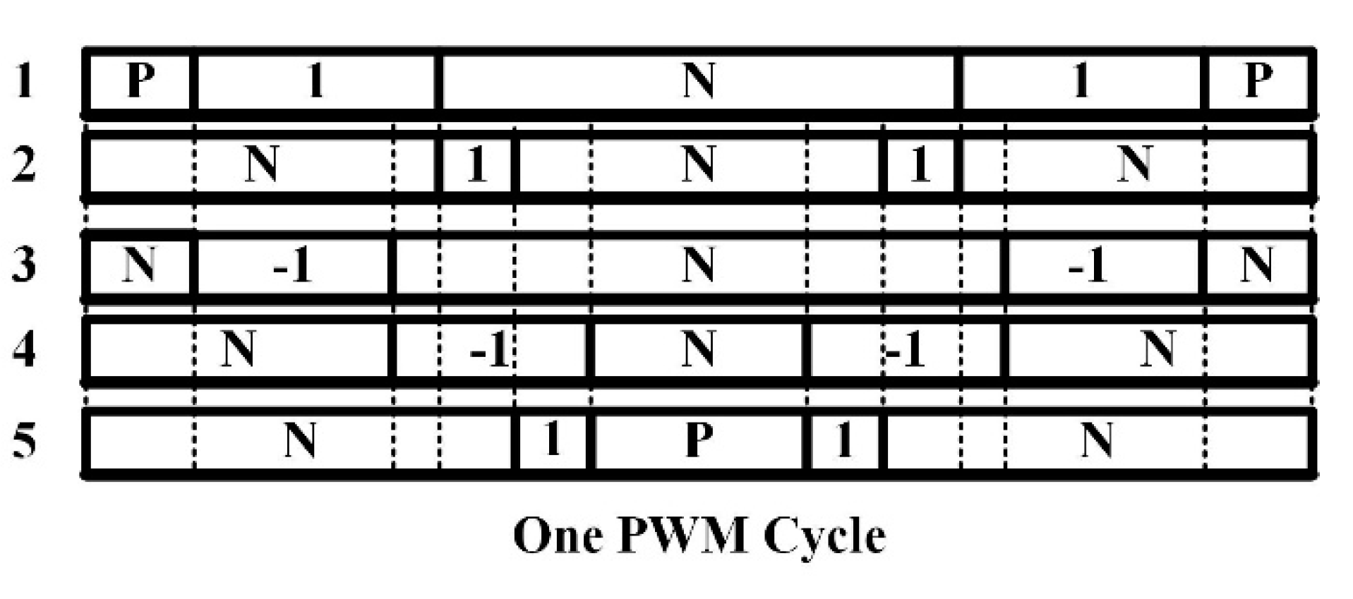
2. Impulse Current PWM Technique

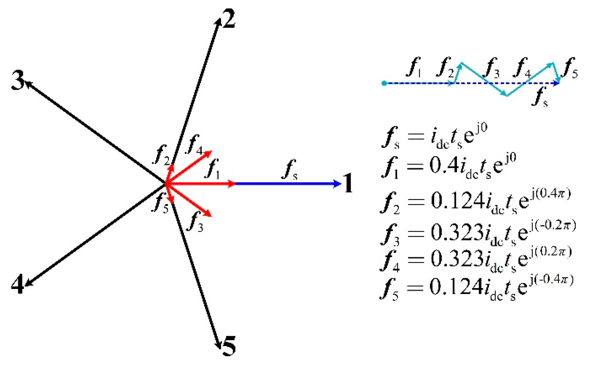
2.1. Mathematical Model of the Impulse Current PWM Technique

The five-phase current source driver includes the buck converter and the five-phase CSI as shown in Figure 1. The buck converter provides a constant DC-link current as the current source. The five-phase CSI has five arms and provides power to the motor. Unlike a voltage source inverter (VSI), CSI requires the diodes to block the freewheeling current of the semiconductor switch, such as D1~D10. Because the outputs of CSI are square currents and the PMSM windings show inductance characteristics, the capacitors are required as the filter, such as C1~C5.
Based on the ampere-second balance principle and [29], each phase current impulse of the five-phase CSI is
i k , impulse = i k t s = D k t s i dc , k { 1 , 2 , , 5 } , D k [ 1 , 1 ] ,
where ik,impulse is the current impulse of phase k, ik is the current of phase k, idc is the DC-link current, ts is the switching cycle, and Dk is the duty of phase k. When Dk is positive, the upper semiconductor switch of phase k is on, and the down semiconductor switch of this phase is off. When Dk is negative, the upper semiconductor switch of phase k is off and the lower semiconductor switch of this phase is on. Then, the current of phase k is
i k = D k i dc .
then the duty set D is
D = { D 1 , D 2 , , D 5 } .
Since the sum of phase currents should be zero, the sum of phase duties should also be zero that is
k = 1 5 D k = 0 , D k D .
Sorting the duties in order from large to small, the new duty set d is
d = { d 1 , d 2 , , d 5 } , d k D , k { 1 , 2 , , 5 } ,
where didi+1, did, i ∈ {1, 2, 3, 4}. The sort mappings can be defined as
[ d 1 , d 2 , , d 5 ] T = A [ D 1 , D 2 , , D 5 ] T ,
where A is the square matrix of order 5 that is
A = [ A 11 A 15 A 51 A 55 ] .
for Ai,j, i, j ∈ {1, 2, …, 5}, when
d i = D j , d i d , D j D ,
then Ai,j = 1; otherwise, Ai,j = 0. Matrix A in (7) is used to present the mapping relationship between [D1, D2, …, D5]T and [d1, d2, …, d5]T. As the change of [D1, D2, …, D5]T, A will change simultaneously. In practical applications, matrix A in (7) is not used for actual calculations, but only for convenient mathematical expressions. In fact, [d1, d2, …, d5]T can be obtained from [D1, D2, …, D5]T by the unified sorting algorithm. For example, when D1 = −0.224, D2 = 0.144, D3 = 0.312, D4 = 0.05, D5 = −0.282, then d1 = 0.312, d2 = 0.144, d3 = 0.05, d4 = −0.224, d5 = −0.282 after sorting [D1, D2, …, D5]T from the largest to smallest. Additionally, A is
A = [ 0 0 1 0 0 0 1 0 0 0 0 0 0 1 0 1 0 0 0 0 0 0 0 0 1 ] .
Unlike the space current vector selection of the SVPWM, the impulse-PWM technique can generate the PWM waveforms based on the sorting algorithm and the inverse sorting algorithm, which is easy to implement. Since the sum of the phase duties is zero and the duties of each phase cannot all be zero during normal operation, there must be an integer p that can meet the requirement
d p 0 , d p + 1 < 0 , p { 1 , 2 , 3 , 4 } .
Then, the sum dsum of the positive duties is
d sum = k = 1 p d k , d k > 0 .
When dsum > 1, it represents that the system has been in the over-modulation area, and duty set d should be modified to
d = { d k | d k = d k d sum , d k d } .
Then, duty cycle set Dg can be obtained as
D g = { d , d sum 1 d , d sum > 1 .
According to duty set Dg, comparison point set Tg can be further obtained as
T g = { T 1 , T 2 , , T p , T p + 1 , T p + 2 , , T 5 } ,
and any comparison point Tk is
T k = { t 0 4 , t 0 = 1 i = 1 p d i , k = 1 T k 1 + d k 1 2 , k { 2 , 3 , , p } T k + 1 + d k + 1 2 , k { p + 1 , p + 2 , , 4 } t 0 4 , t 0 = 1 i = 1 p d i , k = 1 ,
where di, dk−1, dk+1Dg, Tk−1, Tk+1Tg. When generating the PWM waveform, similar to the SVPWM, the carrier adopts unipolar triangular carrier Tcmp, and the carrier amplitude is set as 0.5, and the frequency is fs, then the PWM wave set G is
G = { p 1 , p 2 , , p 5 } ,
where pkG, TkTg, dkDg, k ∈ {1, 2, …, 5}, and pk is
p k = { 1 , T k T cmp < T k + d k 2 , d k > 0 1 , | T k | T cmp < | T k + d k 2 | , d k < 0 P , T cmp < | T 1 | , o r , T cmp > | T p + d p 2 | N , T cmp < | T k | , k 1 , o r , T cmp > | T k + d k 2 | , k p ,
and pk = 1 represents that the upper semiconductor switch of phase k is on and the lower semiconductor switch is off; pk = −1 represents that the lower semiconductor switch is on and the upper semiconductor switch is off; pk = P represents that the upper and lower semiconductor switches conduct simultaneously; and pk = N represents that the upper and lower semiconductor switches are both off. Since the order of each element in matrix G is that, after the duty ordering, it needs to be mapped to the natural phase order through reverse ordering that is
G nature = A 1 G .
This paper takes the five-phase dual-rotor PMSM as an example, and there are five impulse current vectors, which are f1, f2, f3, f4, and f5, respectively. Additionally, the corresponding impulse current vector duties are D1, D2, D3, D4, and D5. When the duty is positive, the impulse current vector is also positive, and it presents that the upper semiconductor of this phase turns on and the lower semiconductor turns off. In contrast, when the duty is negative, the impulse current vector is negative, and it presents that the lower semiconductor of this phase turns on and the upper semiconductor turns off. When the duty is zero, this phase has zero impulse current vectors, and both semiconductors of this phase turn on or off at the same time. According to the vector synthesis technique, the target impulse current vector can be synthesized by the five-phase impulse current vectors. Therefore, the control of the target impulse current vector can be realized by individually controlling the five-phase impulse current vector. For example, when the target impulse current vector is fs = idctsej0, θe = 0, the five-phase impulse current vectors are f1 = 0.4idctsej0, f2 = 0.124idctsej(0.4π), f3 = 0.323idctsej(−0.2π), f4 = 0.323idctsej(0.2π), and f5 = 0.124idctsej(−0.4π), respectively, with the control strategy of id = 0 and the equal power Clarke transformation. Additionally, the impulse current vector’s distribution and the synthesis process are shown in Figure 2, where 1~5 present the phase A~E.
According to the feature of the current source inverter, a current path needs to be maintained at any time; that is, one upper semiconductor switch and one lower semiconductor switch need to be turned on at any time. Therefore, during one switching cycle, there are two different cases. One is named the zero impulse current area, and the other is named the active impulse current area. In the zero impulse current area, both the upper and lower semiconductors of one phase need to be turned on simultaneously, which are selected by the principle of the minimal switching number. In the active impulse current area, one positive impulse current vector duty and one negative duty need to be selected, and the corresponding semiconductors need to be turned on. According to the magnitude relationship and the polarity conditions of the five-phase impulse current duties, the action order can be determined by sorting these duties from large to small, and then the PWM waveform can be generated. For example, when the duties are D1 = 0.4, D2 = 0.124, D3 = −0.323, D4 = −0.323, D5 = 0.124, the action order of the five-phase impulse current duties can be shown in Figure 3.

2.2. The DC-Link Current Ratio with a Five-Phase Motor Drive System

The DC-link current ratio is defined as the ratio of the inverter’s maximum output current amplitude to the bus current. Since the five-phase star connection is adopted, the phase current is equal to the line current, so the inverter’s maximum output current amplitude is the maximum phase current amplitude.
In the case that the harmonic currents are zero, the motor has five-phase symmetrical currents. From Equation (2), the impulse duties are also five-phase symmetrical duties. Without affecting the results, the five-phase duties can be assumed as:
{ d 1 = D amp cos ( θ e ) d 2 = D amp cos ( θ e φ ) d 3 = D amp cos ( θ e 2 φ ) d 4 = D amp cos ( θ e 3 φ ) d 5 = D amp cos ( θ e 4 φ ) ,
where θe is the electric angle, Damp is the amplitude. Calculate the sum of all positive duties; the maximum sum of all positive duties is 1.618Damp. Since the sum of all positive duties must be less than or equal to 1, the maximum value of Damp is 0.618, and the maximum value of the output phase current is 0.618idc; that is, the DC-link current ratio is 0.618.
When the SVPWM is adopted, the 25 space current vectors can be divided into 3 groups, namely 10 large vectors with the amplitude of 1.902idc, 10 small vectors with the amplitude of 1.176idc, and 5 zero vectors. When the SVPWM with adjacent four vectors is used, the ratio of the action time between the small and large vectors should be 0.618 in order to turn the output third harmonic current to zero. Therefore, a set of middle vectors with an amplitude of 1.625idc can be synthesized from the large and small vectors. In the vector space, the tangent circle of these 10 middle vectors is obtained, and its amplitude is 1.625idccos(π/10) = 1.545idc. When the motor has the five-phase symmetrical currents, the amplitude of the resultant space current vector is 2.5Iamp, and Iamp is the amplitude of the phase current. The maximum value of the resultant space current vector is 2.5Iamp = 1.545idc; that is, Iamp = 0.618idc and the DC-link current ratio is also 0.618.

3. Harmonic Suppression Method for the nth Harmonic Current

3.1. The Analysis of the nth Harmonic Current in the mth Harmonic Space

According to the Fourier Transformation, any periodic signal can be obtained by the superposition of a series of sines and cosines. Therefore, without affecting generality, the nth harmonic currents of the five-phase currents are
{ i a , n = I n cos ( n ω t + φ n ) i b , n = I n cos ( n ω t 2 n π / 5 + φ n ) i c , n = I n cos ( n ω t 4 n π / 5 + φ n ) i d , n = I n cos ( n ω t 6 n π / 5 + φ n ) i e , n = I n cos ( n ω t 8 n π / 5 + φ n ) ,
where θe is the electrical angle, φn is the initial phase of the nth harmonic current, In is the amplitude of the nth harmonic current, n is the number of the harmonic current, and ia,n~ie,n are nth harmonic currents of five phases, respectively.
Since it is more convenient to use the equal power transformation, and the equal power transformation and equal amplitude transformation do not affect the analysis results of the harmonic current, this paper adopted the equal power Clarke transformation. In the mth harmonic space, the mth Clarke transformation matrix T52,m is
T 52 , m = 2 5 [ 1 cos ( m φ ) cos ( 2 m φ ) cos ( 3 m φ ) cos ( 4 m φ ) 0 sin ( m φ ) sin ( 2 m φ ) sin ( 3 m φ ) sin ( 4 m φ ) ] ,
where φ = 2π/5 and m is the number of the harmonic space.
Transform the nth harmonic current and the results are as follows:
  • When n ∈ {x|x = 5km, kZ};
{ i α , n , m = 10 I n 2 cos ( n θ e + φ n ) i β , n , m = 10 I n 2 sin ( n θ e + φ n ) .
2.
When n ∈ {x|x = 5k + m, kZ};
{ i α , n , m = 10 I n 2 cos ( n θ e + φ n ) i β , n , m = 10 I n 2 sin ( n θ e + φ n ) .
3.
When n ∉ {x|x = 5k ± m, kZ};
{ i α , n , m = 0 i β , n , m = 0 .
and iα,n,m and iβ,n,m are the α–β axis components in the mth harmonic space, respectively.
From the results, the α–β axis components of the nth harmonic current are either sinusoidal or 0. In general, the PI controller is used for current control. However, the traditional PI controller cannot realize the station-free tracking of sinusoidal quantity because it has only one internal mode of step signal. Therefore, it is very difficult to control the harmonic current in this coordinate system, and further transformation is needed.
In the mth harmonic space, the Park transformation matrix Tsr,m is
T sr , m = [ cos ( m θ e ) sin ( m θ e ) sin ( m θ e ) cos ( m θ e ) ] .
Furthermore, the transformation results are as follows:
4.
When n ∈ {x|x = 5km, kZ};
{ i d , n , m = 10 I n 2 cos [ ( n + m ) θ e + φ n ] i q , n , m = 10 I n 2 sin [ ( n + m ) θ e + φ n ] .
5.
When n ∈ {x|x = 5k + m, kZ};
{ i d , n , m = 10 I n 2 cos [ ( n m ) θ e + φ n ] i q , n , m = 10 I n 2 sin [ ( n m ) θ e + φ n ] .
6.
When n ∉ {x|x = 5k ± m, kZ};
{ i d , n , m = 0 i q , n , m = 0 .
and id,n,m and iq,n,m are the d–q axis components in the mth harmonic space, respectively.
From the above results, when n ∈ {x|x = 5km, kZ}, the numbers of id,n,m and iq,n,m are all n + m ∈ {x|x = 5k, kZ}. Additionally, when n ∈ {x|x = 5k + m, kZ}, the numbers are all nm ∈ {x|x = 5k, kZ}. It can be observed that id,n,m and iq,n,m are all a constant value when n = m. Consequently, after the transformation in the nth harmonic space, the d–q axis components are all the superposition of a constant component and a series of sinusoidal components. Additionally, only the nth harmonic current transformation results are constant components. Therefore, as long as the low-pass filter is used to extract the constant components, it can be used to control the nth harmonic current.

3.2. Low-Pass Filter SDFT-LPF Based on the Sliding Discrete Fourier Transformation

The Sliding Discrete Fourier Transformation (SDFT) is a frequency-domain tool for signal spectrum analysis, which has the same physical meaning as the Discrete Fourier Transformation (DFT). SDFT is a kind of cyclic algorithm that depends on the previous calculation results. When the signal spectrum is extracted, the calculation amount of spectrum analysis can be greatly reduced. Therefore, the application of SDFT in the actual system can greatly reduce the calculation amount of signal processing.
For the discrete time system signal x(u), the spectrum of N points corresponding to the DFT is
X ( v ) = i = 0 N 1 x ( u ) e j 2 π u v N ,
where u is the time and v is the frequency unit.
According to the Fourier Transformation theory, the time domain difference equation of dynamic discrete Fourier analysis of N-points discrete Fourier frequency unit v in the sliding window at time u is
X u ( v ) = e j 2 π v N [ X u 1 ( v ) + x ( u ) x ( u N ) ] ,
where Xu(v) is the result of frequency v at time u, and Xu-1(v) is the result of frequency v at time u − 1. According to the above formula, the constant component can be extracted as long as v = 0, thus realizing the function of the low-pass filter.
When v = 0,
e j 2 π v N = 1 .
Then, the time domain difference equation is
X u ( 0 ) = X u 1 ( 0 ) + x ( u ) x ( u N ) ,
In actual system, when the cut-off frequency is fr and the switching cycle is ts, then the number of the sample points is
N = 1 f r t s .

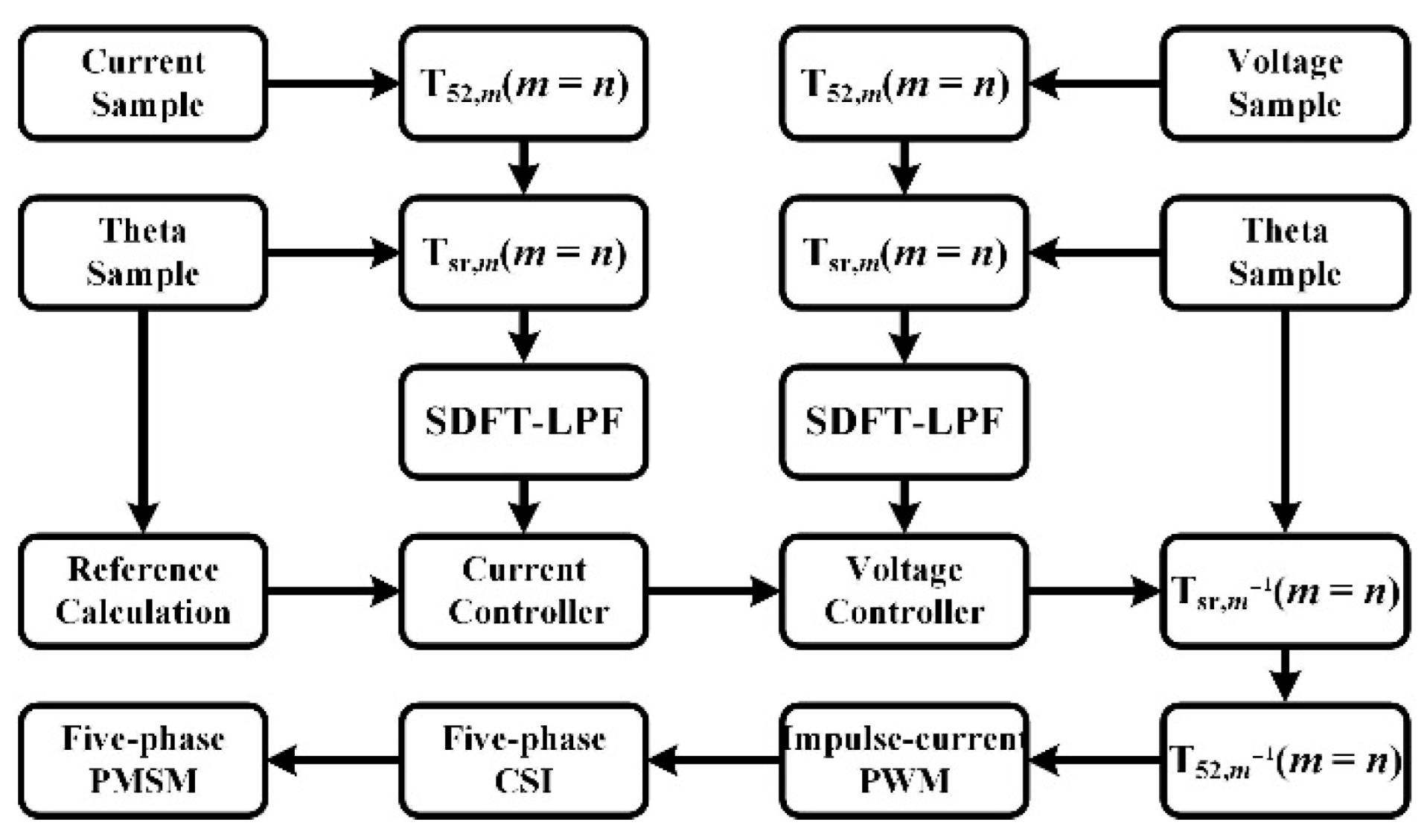
3.3. nth Harmonic Current Suppression Method

From the above derivations, it can be determined that the inputs are the five-phase impulse duties for the impulse modulation strategy of the five-phase CSI. The duties can be obtained by the inverse Park and inverse Clarke transformations of the d–q axis components. In other words, when n = m for the nth harmonic current, the Clarke and Park transformations in the mth harmonic space can be used to transform the five-phase currents, and the constant components of the nth harmonic current can be extracted by the SDFT-LPF in the d–q coordinate frame in the mth harmonic space. Then, the constant components can be used to calculate the duties for closed-loop control, and the impulse current PWM technique can generate the corresponding PWM signal to realize the control of the nth harmonic current. The specific control flowchart is shown in Figure 4.

4. Experimental Results and Discussions

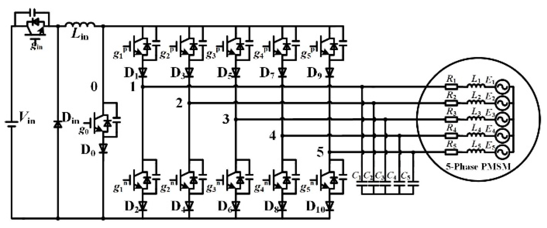
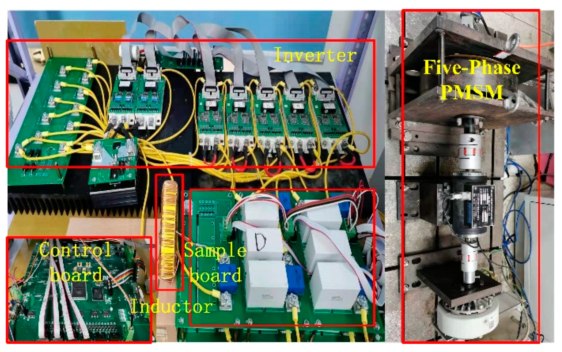
4.1. Experimental Prototype

To verify the effectiveness of the proposed nth harmonic current suppression method and impulse current PWM technique in this paper, a five-phase dual-rotor PMSM drive prototype with the five-phase CSI was built, as shown in Figure 5. The experimental prototype includes the control board, sample board, power semiconductors, DC-link inductor, and the five-phase dual-rotor PMSM. The control board selects the DSP and FPGA to execute the program, the semiconductors utilize the IGBT to build the five-phase CSI, and the sample board selects the hall sensors to sample the current and voltage. The driver parameters are summarized in Table 1 and the motor parameters are summarized in Table 2.

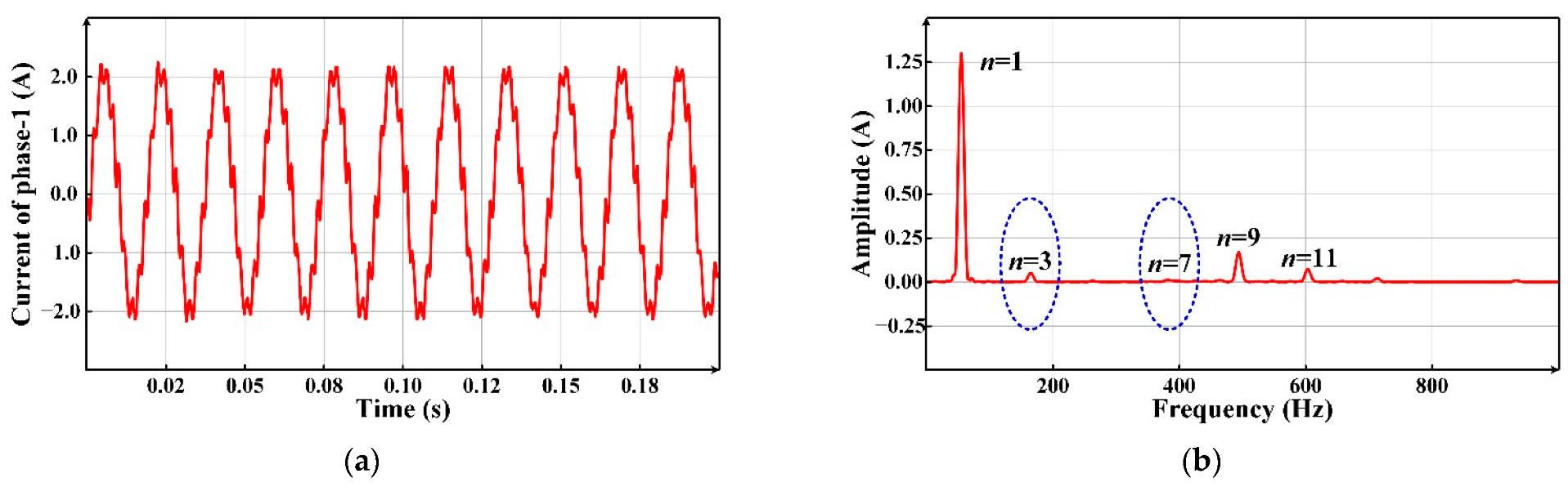
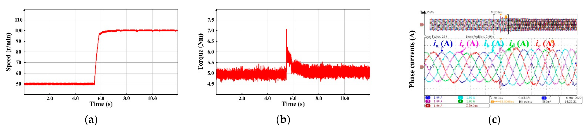
4.2. Normal Operation

The system normal operation experiment results with the proposed impulse current PWM technique and SDFT-LPF are shown in Figure 6 when TL = 5 Nm, Vin = 50 V, and idc = 5 A. From Figure 6a, it can be observed that the speed increases from 50 r/min to 100 r/min at t = 5.5 s with the ripple of 1 r/min. Figure 6b shows that the motor torque increases suddenly with the maximum value of 7.0 Nm when the speed is changed. Figure 6c presents the five-phase currents. When the speed is changed, the frequency of the currents increases from 18.3 Hz to 36.7 Hz. The experimental results indicate that the system can be controlled stably when the proposed impulse modulation strategy is adopted.

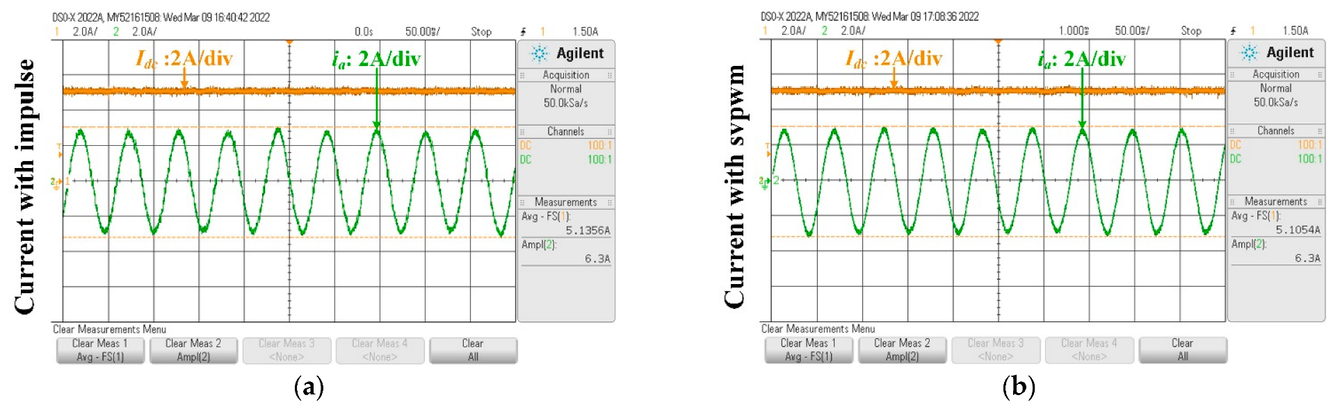
4.3. The DC-Link Current Ratio Experiment

The DC-link current ratio experimental results are shown in Figure 7 when Vin = 50 V, idc = 5 A, and the speed reference nref = 50 r/min. According to the calculation, the maximum DC-link current ratios of the impulse current PWM technique and SVPWM are all 0.618. When the impulse current PWM technique is selected, Figure 7a shows that the maximum phase current amplitude can reach 3.15 A with the DC-link current of 5.1356 A, and hence the DC-link current ratio is 0.613, which is consistent with the theoretical calculation result. When the SVPWM strategy is adopted, Figure 7b shows that the maximum phase current amplitude is also 3.15 A and the DC-link current is 5.1054 A, and the DC-link current ratio is 0.617, which is almost the same as that of the impulse modulation strategy. The experimental results indicate that the two modulations have the same performance in terms of the DC-link current ratio.

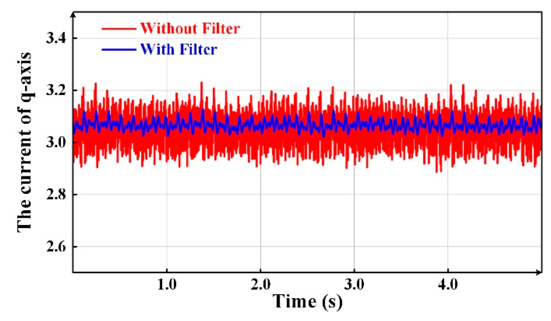
4.4. The Experiment with SDFT-LPF

In order to verify the effectiveness of SDFT-LPF, the experimental results are shown in Figure 8 when Vin = 50 V, idc = 10 A, nref = 50 r/min, TL = 5 Nm. Since the number of pole pairs of the PMSM is 22, then the fundamental frequency of the phase currents is 18.33 Hz. From the above analysis, the d–q axis components are all the superposition of a constant component and a series of sinusoidal components after the transformation of the five-phase currents in the mth harmonic space. When m = 1 and n = 1, according to Equations (26)–(28), the lowest frequency of the sinusoidal components is 183.3 Hz.
Considering the storage space and filtering performance, the sampling points of the SDFT-LPF are selected as 200, so the cut-off frequency is 41.7 Hz, which meets the filtering requirements. Taking the q-axis current component as an example when m = 1 and n = 1, from Figure 8, it can be observed that the average ripple without a filter is 0.0407 A and the maximum ripple is 0.1798 A. After the filter is applied, the average ripple is 0.0155 A and the maximum ripple is 0.0612 A, which are only 38% and 34% of those without a filter, respectively. The experimental results indicate that the filter has a good performance.

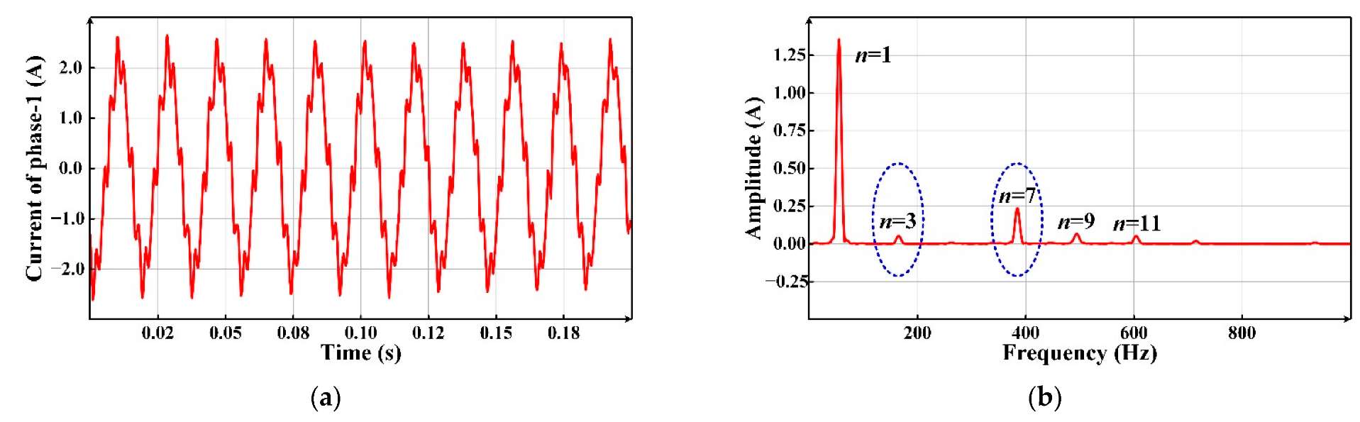
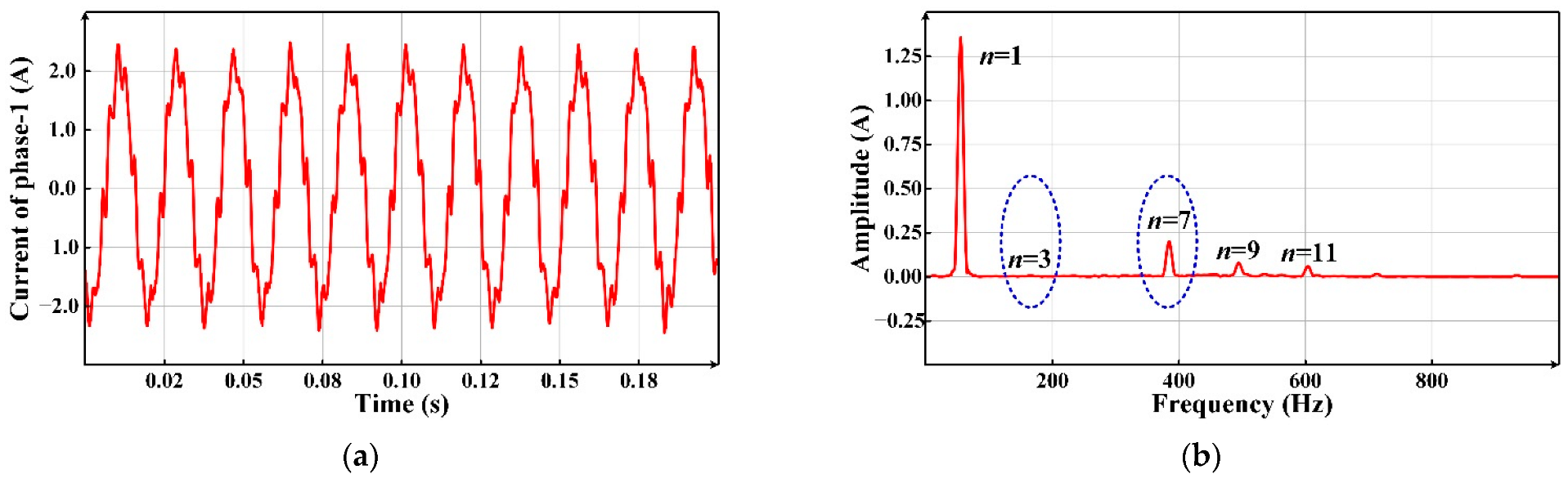
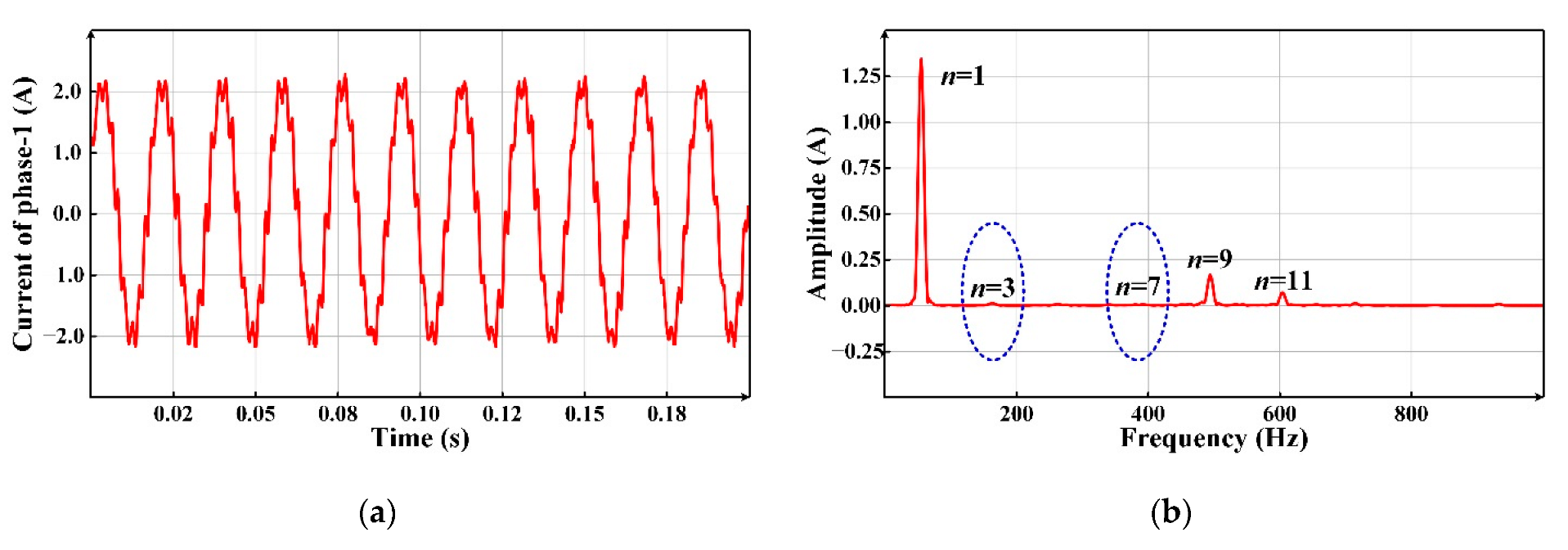
4.5. Harmonic Current Suppression Experiment

In order to verify the effectiveness of the proposed harmonic current suppression method, the harmonic current suppression experimental results are shown in Figure 9, Figure 10, Figure 11 and Figure 12 when Vin = 50 V, idc = 10 A, nref = 150 r/min, TL = 5 Nm. To illustrate the harmonic current control performance, select the third and seventh harmonic currents as control objects and execute the following experiments:
  • The fundamental current control experiment;
  • The fundamental current and third harmonic current control experiment simultaneously;
  • The fundamental current and seventh harmonic current control experiment simultaneously;
  • The fundamental current, third harmonic current, and seventh harmonic current control experiments simultaneously.
The amplitudes of the harmonic current and its percentage to the amplitude of the fundamental current are summarized in Table 3. Due to the magnetic powder brake, the load has a certain fluctuation, so the amplitude of each harmonic current during different times has a slight change, but the change is small and does not affect the experimental conclusion. It can be observed from Table 3 that, in experiment 1, the third, seventh, ninth, and eleventh harmonic currents are all obvious, and the percentages of the fundamental currents are 3.9%, 17.5%, 4.9%, and 3.8%, respectively. In experiment 2, it can be observed that the third harmonic current can be controlled independently, and its amplitude percentage is reduced to 0.5%, while the seventh harmonic current amplitude percentage is 14.7%. In experiment 3, the seventh harmonic current amplitude percentage is reduced to 0.8%, while the third harmonic current amplitude percentage is 3.9%. Experiments 2 and 3 show that the proposed harmonic current suppression method can realize the independent control for the harmonic current. In experiment 4, it can be observed that the third harmonic current amplitude percentage is reduced to 0.9% and the seventh harmonic current amplitude percentage is reduced to 0.3%. It is shown that the harmonic current suppression method can realize the simultaneous control of different harmonic currents.

5. Conclusions

For multi-phase PMSM, there are many harmonic currents, which are difficult to control accurately. To solve this problem, this paper took a five-phase dual-rotor PMSM fed with a current source inverter (CSI) as an example, and proposed an nth harmonic current control method based on the impulse current PWM algorithm. By analyzing the nth harmonic current in the mth harmonic space, it was found that the d–q axis components were all constant components when n = m; otherwise, they were sinusoidal components or zero. Furthermore, when the five-phase currents were transformed in the mth harmonic space, the results were the superposition of the constant component from the nth (n = m) harmonic current and a series of sinusoidal components from other harmonic currents. Based on the analysis results, the constant components of the nth harmonic current are extracted by the SDFT-LPF. Then, the nth harmonic current could be controlled accurately based on the extracted constant components. For five-phase CSI, the impulse current PWM technique was realized, which had the same DC-link current utilization rate compared to the SVPWM. Additionally, this technique did not need to select the space vectors and calculate the dwell time for each vector. The experiments confirmed that the proposed harmonic current control method can accurately control any nth harmonic current without changing the PWM technique, which increased the selective harmonic control ability significantly, and can be directly extended to the multiple harmonic current’s control. The proposed scheme can be applied to the safety-critical applications to increase the performance of machines, such as electrical vehicles.

Author Contributions

Conceptualization, C.C., Z.C. and C.G.; Data curation, C.C.; Formal analysis, C.C., J.Z. and X.S.; Investigation, C.C., Z.C. and X.L.; Methodology, C.C. and C.G.; Project administration, C.C. and Z.C.; Resources, Z.C.; Software, C.C.; Supervision, Z.C. and X.L.; Validation, C.C., C.G., J.Z. and X.L.; Visualization, C.C., C.G., J.Z. and X.S.; Writing—original draft, C.C.; Writing—review & editing, C.C., Z.C., J.Z., X.L. and X.S. All authors have read and agreed to the published version of the manuscript.

Funding

This research received no external funding.

Institutional Review Board Statement

Not applicable.

Informed Consent Statement

Not applicable.

Data Availability Statement

Not applicable.

Conflicts of Interest

The authors declare no conflict of interest.

References

  1. Qu, L.; Qiao, W.; Qu, L. An extended-state-observer-based sliding-mode speed control for permanent-magnet synchronous motors. IEEE J. Emerg. Sel. Top. Power Electron. 2021, 9, 1605–1613. [Google Scholar] [CrossRef]
  2. Xu, W.; Junejo, A.K.; Liu, Y.; Islam, M.R. Improved continuous fast terminal sliding mode control with extended state observer for speed regulation of PMSM drive system. IEEE Trans. Veh. Technol. 2019, 68, 10465–10476. [Google Scholar] [CrossRef]
  3. Tan, L.N.; Cong, T.P.; Cong, D.P. Neural network observers and sensorless robust optimal control for partially unknown PMSM with disturbances and saturating voltages. IEEE Trans. Power Electron. 2021, 36, 12045–12056. [Google Scholar] [CrossRef]
  4. Kim, S.; Ahn, C.K. Offset-free proportional-type self-tuning speed controller for permanent magnet synchronous motors. IEEE Trans. Ind. Electron. 2019, 66, 7168–7176. [Google Scholar] [CrossRef]
  5. Mori, H.; Matsui, K.; Kondo, K.; Yamamoto, I.; Hasegawa, M. Parallel-connected five-level PWM inverters. IEEE Trans. Power Electron. 2003, 18, 173–179. [Google Scholar] [CrossRef]
  6. Maia, A.C.N.; Jacobina, C.B.; Freitas, N.B.; da Silva, I.R.F.M.P. Open-end multilevel six-phase machine drive system with five three-leg converters. IEEE Trans. Ind. Appl. 2017, 53, 2271–2281. [Google Scholar] [CrossRef]
  7. Bourhichi, S.E.; Oukassi, A.; el Adnani, M. Indirect vector control of induction motor using a five-level cascaded H-bridge inverter. In Proceedings of the 2018 International Symposium on Advanced Electrical and Communication Technologies (ISAECT), Rabat, Morocco, 21–23 November 2018. [Google Scholar]
  8. Rakesh, R.; Majumder, M.G.; Gopakumar, K.; Umanand, L.; Cecati, C.; Zielinski, D. A dense multilevel 30-sided space vector generation using a single DC link for an induction motor drive. IEEE Trans. Power Electron. 2021, 36, 11681–11690. [Google Scholar]
  9. Rakesh, R.; Majumder, M.G.; Dewani, R.; Gopakumar, K.; Loganathan, U.; Jarzyna, W.; Franquelo, L.G. A very high resolution 30-sided space vector generation from a single DC-link for induction motor drives. IEEE Trans. Ind. Electron. 2022, 69, 160–168. [Google Scholar]
  10. Fernandez, L.D.P.; Rodriguez, J.L.D.; Carvajal, M.A.J. Three-phase multilevel inverter with selective harmonic elimination. In Proceedings of the 2015 Workshop on Engineering Applications—International Congress on Engineering (WEA), Bogota, Colombia, 28–30 October 2015. [Google Scholar]
  11. Abrishamifar, A.; Arasteh, M.; Golshan, F. A novel method for real-time selective harmonic elimination in five-level converters. In Proceedings of the 2016 7th Power Electronics and Drive Systems Technologies Conference (PEDSTC), Tehran, Iran, 16–18 February 2016. [Google Scholar]
  12. Castiglia, V.; Miceli, R.; Schettino, G.; Cimoroni, M.G.; Buccella, C.; Cecati, C. Selective harmonic elimination in a 5-level single phase converter with FPGA based controller. In Proceedings of the 2018 5th International Symposium on Environment-Friendly Energies and Applications (EFEA), Rome, Italy, 24–26 September 2018. [Google Scholar]
  13. Yu, F.; Zhang, X.; Wang, S. Five-phase permanent magnet synchronous motor vector control based on harmonic eliminating space vector modulation. In Proceedings of the 2005 International Conference on Electrical Machines and Systems, Nanjing, China, 27–29 September 2005. [Google Scholar]
  14. Kaarthik, R.S.; Gopakumar, K.; Cecati, C.; Nagy, I. Timing calculations for a general N-level dodecagonal space vector structure using only reference phase voltages. IEEE Trans. Ind. Electron. 2016, 63, 1395–1403. [Google Scholar] [CrossRef]
  15. Booin, M.B.; Cheraghi, M. THD minimization in a five-phase five-level VSI using a novel SVPWM technique. In Proceedings of the 2019 10th International Power Electronics, Drive Systems and Technologies Conference (PEDSTC), Shiraz, Iran, 12–14 February 2019. [Google Scholar]
  16. Heidari, H.; Rassõlkin, A.; Vaimann, T.; Kallaste, A.; Taheri, A.; Holakooie, M.H.; Belahcen, A. A novel vector control strategy for a six-phase induction motor with low torque ripples and harmonic currents. Energies 2019, 12, 112. [Google Scholar] [CrossRef] [Green Version]
  17. Wang, T.; Yang, J. A direct torque control strategy of five-phase induction motor with duty cycle optimization. In Proceedings of the 2014 17th International Conference on Electrical Machines and Systems (ICEMS), Hangzhou, China, 22–25 October 2014. [Google Scholar]
  18. Payami, S.; Behera, R.K. An improved DTC technique for low-speed operation of a five-phase induction motor. IEEE Trans. Ind. Electron. 2017, 64, 3513–3523. [Google Scholar] [CrossRef]
  19. Pandit, J.K.; Aware, M.V.; Nemade, R.V.; Levi, E. Direct torque control scheme for a six-phase induction motor with reduced torque ripple. IEEE Trans. Power Electron. 2017, 32, 7118–7129. [Google Scholar] [CrossRef] [Green Version]
  20. Tatte, Y.N.; Aware, M.V. Torque ripple and harmonic current reduction in a three-level inverter-fed direct-torque-controlled five-phase induction motor. IEEE Trans. Ind. Electron. 2017, 64, 5265–5275. [Google Scholar] [CrossRef]
  21. Zhou, H.; Xu, J.; Chen, C.; Tian, X.; Liu, G. Disturbance-observer-based direct torque control of five-phase permanent magnet motor under open-circuit and short-circuit faults. IEEE Trans. Ind. Electron. 2021, 68, 11907–11917. [Google Scholar] [CrossRef]
  22. Huang, W.; Hua, W.; Chen, F.; Hu, M.; Zhu, J. Model predictive torque control with SVM for five-phase PMSM under open-circuit fault condition. IEEE Trans. Power Electron. 2020, 35, 5531–5540. [Google Scholar] [CrossRef]
  23. Guo, Y.; Yu, B.; Li, S.; Zhu, Y.; Song, W. A FCS-MPC method based on simplified control set for five-phase PMSMs. In Proceedings of the 2021 IEEE International Conference on Predictive Control of Electrical Drives and Power Electronics (PRECEDE), Jinan, China, 20–22 November 2021. [Google Scholar]
  24. Liu, S.; Liu, C.; Song, Z.; Dong, Z.; Huang, Y. Candidate modulation patterns solution for five-phase PMSM drive system. IEEE Trans. Transp. Electrif. 2022, 8, 1194–1208. [Google Scholar] [CrossRef]
  25. Arafat, A.K.M.; Choi, S. Active current harmonic suppression for torque ripple minimization at open-phase faults in a five-phase PMa-SynRM. IEEE Trans. Ind. Electron. 2019, 66, 922–931. [Google Scholar] [CrossRef]
  26. Liu, H.; Wang, D.; Yi, X.; Meng, F. Torque ripple suppression under open-phase fault conditions in a five-phase induction motor with harmonic injection. IEEE J. Emerg. Sel. Top. Power Electron. 2021, 9, 274–288. [Google Scholar] [CrossRef]
  27. Pereira, L.A.; Scharlau, C.C.; Pereira, L.F.A.; Haffner, S. Influence of saturation on the airgap induction waveform of five-phase induction machines. IEEE Trans. Energy Convers. 2012, 27, 29–41. [Google Scholar] [CrossRef]
  28. Xu, Y.; Wang, Z.; Liu, P.; He, J. A soft-switching current-source-inverter-fed motor drive with reduced common-mode voltage. IEEE Trans. Ind. Electron. 2021, 68, 3012–3021. [Google Scholar] [CrossRef]
  29. Chen, C.; Chen, Z.; Zhao, J.; Guo, Y.; Liao, X. An impulse modulation strategy for the M-phase permanent magnet synchronous motor with the current source inverter. In Proceedings of the 2022 International Conference on Power Energy Systems and Applications (ICoPESA), Singapore, 25–27 February 2022. [Google Scholar]
Figure 1. The topology of the five-phase current source driver.
Energies 15 04394 g001
Figure 2. The synthesized vector and the impulse current vector’s distribution.
Energies 15 04394 g002
Figure 3. The action order of the five-phase impulse current duties in one PWM cycle.
Energies 15 04394 g003
Figure 4. The specific control flowchart of the nth harmonic current.
Energies 15 04394 g004
Figure 5. Experimental prototype with the five-phase CSI.
Energies 15 04394 g005
Figure 6. Normal operation experiment with the impulse current PWM technique and SDFT-LPF: (a) speed; (b) torque; (c) phase currents.
Energies 15 04394 g006
Figure 7. The DC-link current ratio: (a) impulse current PWM technique; (b) SVPWM.
Energies 15 04394 g007
Figure 8. The q-axis current when m = 1 and n = 1 with or without filters.
Energies 15 04394 g008
Figure 9. Harmonic current suppression results with fundamental currents: (a) phase-1 current; (b) DFT results.
Energies 15 04394 g009
Figure 10. Harmonic current suppression results with fundamental currents and third harmonic current: (a) phase-1 current; (b) DFT results.
Energies 15 04394 g010
Figure 11. Harmonic current suppression results with fundamental currents and seventh harmonic current: (a) phase-1 current; (b) DFT results.
Energies 15 04394 g011
Figure 12. Harmonic current suppression results with fundamental currents, third harmonic current and seventh harmonic current: (a) phase-1 current; (b) DFT results.
Energies 15 04394 g012
Table 1. Parameters of the driver.
SymbolParameterValue
VinInput voltage50
Ldc-linkDC-link inductance13 mH
tsSwitching cycle120 μs
CCapacitor of the filter90 μF
Table 2. Parameters of the five-phase dual-rotor PMSM.
SymbolParameterValue
PNo. of pole pairs22
RWinding resistance0.65 Ω
Ldd-axis inductance0.689 mH
Lqq-axis inductance0.689 mH
ωRated speed150 r/min
TeRated torque18 Nm
ψfRotor flux linkage0.072 Wb
JMoment of inertia0.0625 kg‧m−2
Table 3. Harmonic current suppression results.
The Experiment and Harmonic Current Order1234
11.356 A/100%1.358 A/100%1.300 A/100%1.345 A/100%
30.053 A/3.9%0.007 A/0.5%0.051 A/3.9%0.012 A/0.9%
70.237 A/17.5%0.200 A/14.7%0.011 A/0.8%0.004 A/0.3%
90.067 A/4.9%0.077 A/5.7%0.161 A/12.4%0.162 A/12.0%
110.052 A/3.8%0.058 A/4.3%0.068 A/5.2%0.070 A/5.2%
Publisher’s Note: MDPI stays neutral with regard to jurisdictional claims in published maps and institutional affiliations.

