Article

Utilization Optimization of Capacitive Pulsed Power Supply in Railgun

1
Department of Ammunition Engineering, Army Engineering University, Shijiazhuang 050003, China
2
State Key Laboratory of Explosion Science and Technology, Beijing Institute of Technology, Beijing 100081, China
3
School of Energy and Environmental Engineering, Hebei University of Technology, Tianjing 300401, China
*
Author to whom correspondence should be addressed.
Energies 2022, 15(14), 5051; https://doi.org/10.3390/en15145051
Submission received: 24 May 2022 / Revised: 27 June 2022 / Accepted: 7 July 2022 / Published: 11 July 2022

Abstract

:
The excitation pulse current used to drive the railgun needs to present very a high magnitude (hundreds of kA) flat-top with very low ripple. At present, the main method to obtain this current is to increase the number of the capacitive pulsed power supply (PPS) modules. However, low utilization and massive volume of the railgun system would occur with this method, hampering the application of railgun. Therefore, the utilization optimization technology of PPS is researched in this paper. In order to obtain highly stable flat-top current, the control strategy of the capacitive PPS is designed, and a new charging voltage configuration is proposed, which significantly decreases the use of the capacitive modules. Besides, a miniaturization transformation scheme of capacitive PPS is proposed based on the control strategy. The result shows that the flat-top current ripple has the biggest influence on the PPS utilization, and the smaller the flat-top current ripple, the lower the utilization. When the current with 200 kA magnitude and 0.75% flat-top current ripple is achieved, an 81.9% decrease of volume and a 428.7% utilization improvement are achieved through miniaturization transformation.

1. Introduction

As a kind of ultra-high-speed kinetic energy weapon, the electromagnetic railgun has the advantage of insignificant launch characteristics and great launch speed. It can be applied in many fields such as long-range fire support, air defense, and anti-missile when deployed on chariot or warship [1]. Since the excitation current of the railgun is powerful, a PPS that is charged by the primary power supply and discharged by the railgun at high power is essential. According to the core component of the railgun system, the PPS generally takes the most space. The utilization optimization technology of PPS has become an important factor restricting the application of railgun, especially under the situation where the energy storage density of power supply is difficult to achieve a breakthrough [2].
The PPS applied in railgun system mainly includes a flywheel generator, inductive PPS, and capacitive PPS [3]. The flywheel generator has the highest energy storage density and can output strong current continuously. However, the low power density and powerful rotational inertia make it unsuitable for mobile platforms such as chariots [4]. The inductive PPS has the advantage of high energy density and small volume, and mainly adopts the Meat Grinder circuit to improve the current [5]. Therefore, the inductive PPS is greatly affected by the coupling coefficient. Besides, the high voltage impulse caused by the shutdown of strong current is inevitable, which hinders the engineering of the inductive PPS [6]. The capacitive PPS has been most widely applied due to the simple structure and strong stability. Compared with the two PPSs, the energy density of capacitive PPS is much smaller, so it is used in the form of capacitor bank to power the railgun generally [7]. However, this also brings a new problem: the capacitor bank takes too much space, as shown in Figure 1. Therefore, reducing the volume of the capacitive PPS is crucial to promote its application in railgun.
It is essential to carry out the miniaturization design of the capacitive PPS according to the requirement of excitation current. Previous research has shown that the railgun’s projectile is subjected to stable accelerating force with the excitation of stable current, which is beneficial to reduce the transition, so the excitation current is always adjusted to a square waveform [8]. To obtain ideal current waveform, the most commonly used method is to design the trigger strategy of the capacitive PPS [9,10,11,12]. Some researchers adopt the genetic algorithm to optimize the trigger sequence and use the global search ability of the algorithm to obtain the optimal solution [13,14,15], and the flat-top current with a ripple of 1.24% is achieved. Other researchers adopt the iteration-based method to calculate the optimal trigger sequence. Zhang et al. introduced a current control strategy to keep the current peak in each pulse the same [16] and obtained a strong current of 414 kA/3 ms. Liu et al. also introduced one that keeps the current trough in each pulse the same [17], improved it later, and successfully restricted the current oscillation within 590 kA and 600 kA [10]. However, the above achievement is at the cost of more than 20 capacitive modules. The reason causing such a huge PPS system is that the energy actually used is far below the rated energy of the PPS system [18]. Besides, there exists a common point that the above researchers all adopted the consistent voltage charging method (CVCM), which is a restriction for giving full play to the capacity of capacitive PPS and leading to more modules, low utilization, and bigger volume.
Therefore, according to the requirement of railgun excitation current, this paper designed the control strategy of the capacitive PPS. A numerical simulation was conducted, and a highly stable flat-top current was obtained. Besides, the miniaturization transformation scheme of capacitive PPS was proposed based on the optimization results. The research results show that the capacitive PPS utilization is significantly improved.

2. The Obtainment of Highly Stable Flat-Top Current Based on Capacitive PPS

Powered by the capacitive PPS, the excitation circuit topology of the railgun is shown in Figure 2.
As shown in Figure 2, the circuit topology consists of several pulsed forming units (PFUs), including the capacitor Ci, the thyristor switch THi, the current limiter Li, and the freewheeling diode. Ri is the resistance of the current limiter, Di is the freewheeling diode, Rsi is the on-resistance of Di, Rload and Lload are the respective equivalent resistance and the inductance of the railgun, and Ii is the current supplied by the i-th PFU. Line resistance and line inductance are considered by adjusting the magnitude of Li, Ri, and Rsi. During the working process of the circuit, the high voltage charger is firstly used to charge i-th PFU to a high voltage Ui, and then the thyristor THi will receive the trigger signal and conduct at the moment ti. In this way, the sequence discharge of the capacitive PPS is achieved.

2.1. The Mathematical Model of the Load Current

For a single PFU, depending on whether the capacitor voltage reverse, the discharging process can be divided into two stages: the capacitive energy release stage and the freewheeling stage. The output current can be solved by the analytic method easily. However, the discharging process of different PFU will overlap during the working process of the whole capacitive PPS system, which causes difficulty in adopting the analytic method. Previous research has shown that the numerical method is accurate and effective when working on the complex circuit method. Therefore, based on the numerical method, this paper developed the mathematical model of the discharging process. According to the Runge Kuta algorithm, if the dIload/dt is already known, the load current can be solved by setting the appropriate time step.
Assume that n PFUs are in the freewheeling stage and m PFUs are in the capacitive energy release stage at some point; then, the circuit can be simplified as Figure 3 shows.
In Figure 3, each PFU will form a loop circuit with the load. According to the Kirchhoff law, the general formula of the circuit loop formed by the PFU in the freewheeling stage can be expressed as follows:
R s i I i + L i d I i d t + R i I i + R l o a d I l o a d + L l o a d d I l o a d d t = 0     ( 1 < i < n )
The general formula of the circuit loop formed by the PFU in the capacitive energy release stage can be expressed as follows:
1 C i t i t I i d t + L i d I i d t + R i I i + R l o a d I l o a d + L l o a d d I l o a d d t = U i     ( n + 1 < i < n + m )
The relationship between the branch current and load current can be expressed as follows:
I l o a d = i = 1 m + n I i
Based on Equations (1)–(3), the equations of the circuit are developed and solved, and the dIload/dt can be expressed as follows:
d I l o a d d t = ( i = 1 n x i L i + i = n + 1 m + n y i L i ) [ 1 + i = 1 m + n L l o a d L i ]
The meaning of xi and yi are shown as follows:
x i = ( R s i I i + R i I i + R l o a d I l o a d )     ( 1 < i < n )
y i = U i 1 C i t i t I i d t R i I i R l o a d I l o a d     ( n + 1 < i < n + m )
The dIload/dt at any point can be calculated based on Equation (4). With an appropriate time step, the current supplied by the capacitive PPS can be solved.

2.2. The Confirmation Experiments of the Mathematical Model

To verify the effectiveness of the mathematical models, three groups of experiments were carried out. In the experiment, the PPS consists of 10 capacitive PFUs, the load consists of two copper bars and a steel semicircle to simulate the railgun. The load current is measured by the Rogowski coil. Besides, based on MATLAB, the mathematical model is developed and run with the same charging voltage configuration and sequence for the experiment. Finally, the comparation is made between the calculations and experimental result, and the difference is analyzed. The experiment devices are shown in Figure 4.
As shown in Figure 4, the output cables are all connected to the current confluence device, and then supply strong current to the load. The Rogowski coil is fixed so that the copper bar just passes through the center of the Rogowski coil. The circuit parameters are shown in Table 1, and the charging voltage configuration and sequence are shown in Table 2.
Based on the above experimental platform and settings, the confirmation experiments of the mathematical model were carried out, the comparison between the calculations and experimental result is shown in Figure 5.
According to Figure 5, with the charging voltage configuration and sequence shown in Table 2, the calculations and the experimental result are basically consistent; however, the former has stronger current. There are two possible reasons. Firstly, the charging process will be automatically cut off when the maximum voltage of the capacitor bank exceeds the set value, since the charging speed of each capacitive PFU is different slightly, the actual energy charged is smaller than the set value. Secondly, the load resistance and inductance are both measured by the RLC instrument under static conditions and affected by the current skin effect, so the actual resistance will be larger in experiment.
Although there exists deviation between the calculations and experimental result, the trend and the magnitude are very consistent with each other. Besides, the error mainly comes from parameters but not the mathematical model, it could be overcome by feedback adjustment of the parameters. Therefore, the effectiveness of the circuit mathematical model can be confirmed.

2.3. Control Strategy of the Capacitive PPS

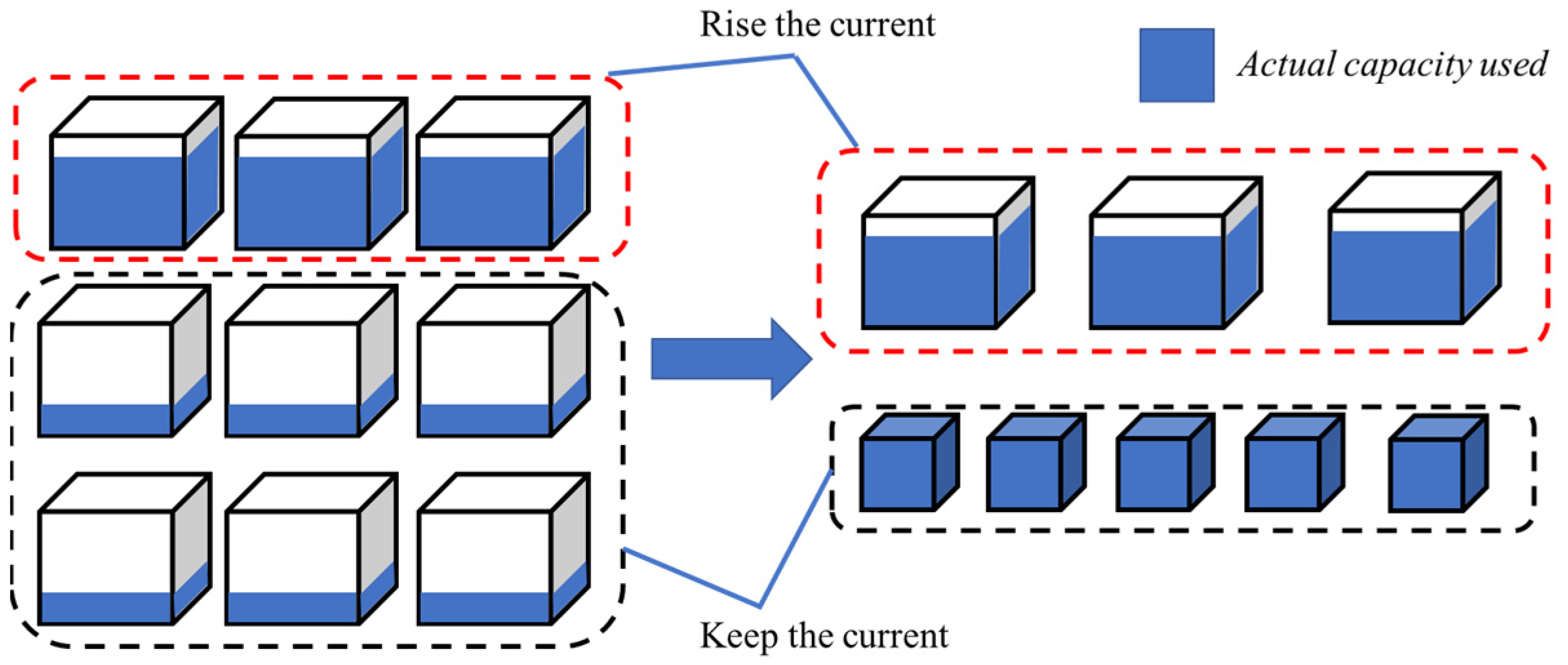
At present, most capacitive PPS adopt CVCM, so all PFUs are charged to the same voltage. CVCM is easy to implement but leads to many restrictions, such as the balance between current stability and system volume. The charging voltage must be very low if a highly stable flat-top current is required, which means more PFUs must be used to meet the current magnitude demand. Therefore, to settle this problem, a diverse voltage charging method (DVCM) and the corresponding control strategy are proposed in this section.
The DVCM adjusts the current waveform by controlling each PFU’s voltage. For each current pulse, we must determine the least PFUs and the appropriate charging voltage that just meets the demand. Calculating the trigger moment of each PFU is achieved by setting the minimum value of current oscillation. The flow chart of the control strategy is shown in Figure 6.
In Figure 6, i is the stage number of PFU and Imax and Imin form the oscillation range of the flat-top current; the smaller the oscillation range, the stabler the current. The flat-top pulse width (FTPD) is defined as the time interval from the first moment that the load current is equal to the flat-top current to the last moment that the load current is equal to the flat-top current. Besides, U0 is the initial iteration value of the charging voltage, ΔU is the iteration step, and Umax is the maximum charging voltage allowed for the PFU. As an intermediate parameter, S is introduced to calculate the number of PFUs discharging simultaneously. The mathematical model is developed based on Equation (4) and Figure 6, and automatic assignment of the trigger sequence and charging voltage optimization is achieved.

2.4. Results and Analysis

The effectiveness of the mathematical model is confirmed in Section 2.2. Therefore, the simulation experiment is mainly adopted to compare and analyze the performance of the DVCM in this section, Liu’s current optimization model is also established. The control strategy of the capacitive PPS in Liu’s model is similar to this paper, but the CVCM is adopted in his research.
Target parameters and restrictions are necessary during the analysis. According to the launching requirement of railgun, the flat-top current magnitude is set to 200 kA, and the FTPD is set to 3 ms. Besides, the flat-top current ripple (FTCR) is defined to quantify the stability of the current, and it can be expressed as follows:
F T C R = m e a n ( | I l o a d , t I f l a t t o p | I f l a t t o p ) × 100 % ( t F T P D )
To obtain stable flat-top current, the target of the FTCR is set to 0.4%. The circuit adopted is shown in Figure 1, and the parameters of components are shown in Table 1. Since the load in Figure 4 is consist of steel semicircle, the resistance measured will be larger than the railgun, and the load resistance is set to 1 mΩ in this section. We run the calculation after completing the above settings, and the results of the two models are shown in Table 3.
As shown in Table 3, with the CVCM, the total PFU adopted in Liu’s model is 47, and all PFUs are charged to 2836 V. Compared with the maximum charging voltage, the actual charging voltage is very small, so 12 PFUs have to discharge simultaneously to meet the flat-top current magnitude demand of 200 kA. Two PFUs are required to keep the flat-top current in each pulse during the platform. However, the charging voltage of the first three PFUs is so high in terms of the DVCM that the flat-top current magnitude demand can be met with the three. Besides, other PFUs are charged to appropriate voltage individually according to Imax, so a single PFU is enough to keep the current in each pulse during the platform. The contrast curve of current obtained with the two charging methods is shown in Figure 7.
In Figure 7, the current waveforms obtained with the two charging methods are basically consistent. Through data processing, the FTCR and the FTPW of the current obtained with CVCM are 0.41% and 3.01 ms, respectively. The FTCR and ECPW of the current obtained with DVCM are 0.43% and 3 ms, respectively. There is no significant difference when evaluating the two charging methods from the performance of the current. However, compared with 47 PFUs adopted in Liu’s model, only 16 PFUs are adopted with the DVCM to obtain the current, which significantly decreases the volume and complexity of the capacitive PPS. Define a parameter η to describe the utilization of the capacitive PPS, and then η can be expressed as follows:
η = W a W r
In Equation (8), Wa is the actual capacity used of the capacitive PPS, and Wr is the rated capacity of the capacitive PPS. According to Equation (8), η is only 8.91% with the CVCM but 33.28% with the DVCM. This is because the ability of each capacitor is brought into greater play with the DVCM. Therefore, the DVCM can increase the utilization of the capacitive PPS, thus decreasing the system volume.

3. Optimization and Improvement of the Capacitive PPS

3.1. The Stepped Charging Method

According to Table 3 and the DVCM, the charging voltage has many values. This is not easy to implement because the capacitive PPS is generally charged with the parallel method. Various charging voltage means more chargers and a more complex system. To settle this problem, this paper proposed a stepped charging method (SCM) that combines the advantage of DVCM and CVCM.
By analyzing the data in Table 3, it is easy to find that the energy magnitude stored in the PFUs that triggers at the initial moment has the most effect on the flat-top current magnitude, and the energy magnitude stored in other PFUs is generally small. Therefore, two kinds of charging voltage can be adopted to charge the capacitive PPS, the higher voltage Ux is used to charge the first several PFUs, and the lower voltage Uy is used to charge other PFUs. Based on the SCM, the current with different stability is obtained. The current curve is shown in Figure 8.
Figure 8 shows that the SCM is excellent in increasing the stability of the flat-top current. The smaller Uy, the smaller FTCR, but the more PFUs and the lower η. Compared with the CVCM, the SCM can use fewer PFUs to obtain a more stable current. Compared with the DVCM, the SCM only uses two chargers, which is easier to implement. Besides, according to the above research, in terms of the SCM, the trigger sequence interval between adjacent PFUs will be consistent over time. This trigger interval is 221 us in Figure 8a and 80.3 us in Figure 8b. That is to say, the circuit is in a cycle state when each PFU discharges in a specific time interval. It is beneficial to extend the capacitive PPS, because there is no need to carry out complex calculations, just add PFU module at a specific time interval.

3.2. Miniaturization Transformation of Capacitive PPS

Although the PFUs used are significantly reduced by the SCM, the utilization η of the capacitive PPS is still very low, and the rated capacity is far beyond the actual capacity when the flat-top current requires high stability, which leads to a waste of space.
The rated capacity Wr of capacitor can be expressed as follows:
W r = 0.5 C U 2
C can be expressed as follows:
C = ε S D
Combine Equations (9) and (10).
W r = ε S U 2 2 D = ε E 2 2 V
In Equation (11), ε is the dielectric constant of the capacitor, E is the breakdown field intensity of the insulating medium, and V is the volume of the capacitor.
According to Equation (11), when the capacitor’s dielectric material remains unchanged and the actual field strength approaches E, the closer the Wr is to the Wa, the smaller the V is. According to above research, energy stored in the first several PFUs is always a lot, but energy stored in other PFUs is relatively less. Therefore, the hybrid application of the large and small capacity capacitor is more reasonable. The diagram of the miniaturization transformation of capacitive PPS is shown in Figure 9.
As Figure 9 shows, before miniaturization transformation, all capacitors are the same and have a capacity of 90.25 kJ. After miniaturization transformation, the first several capacitors charged to high voltage remain unchanged. Other capacitors are transformed into some with smaller capacity according to the actual energy required. The parameter Rη and Rv is introduced to describe the optimization performance of the miniaturization transformation, and R can be expressed as follows:
R η = η a η b η b × 100 %
R V = ( V b V a ) V b × 100 %
In Equation (12), ηa and Va are the utilization and volume of capacitive PPS after transformation, respectively, and ηb and Vb are the utilization and volume of capacitive PPS before transformation, respectively. For the requirement of current with different characteristics, the performance of the miniaturization transformation Rη and Rv are analyzed. The result is shown in Figure 10.
As shown in Figure 10, the current with different magnitude and FTCR is obtained based on the SCV. According to above research, the larger FTCR, the more energy is required, and the performance of the miniaturization transformation is not significant. With the settled maximum FTCR of 10% and current magnitude of 300 kA, the utilization increases by 3.6%, and the volume decreases by 3.53%. However, for the highly stable flat-top current, the performance of the miniaturization transformation is excellent. With the settled minimum FTCR of 0.75% and the current magnitude of 200 kA, the utilization increases by 428.7%, and the volume decreases by 81.08%. Therefore, the miniaturization transformation of capacitive PPS is more suitable for the small-scale railgun with highly stable current requirement.

4. Conclusions

The utilization optimization technology of capacitive PPS applied in railgun was mainly researched in this paper. The equivalent mathematical model of the capacitive PPS is developed and solved based on the iterative method. The optimized charging voltage configuration and trigger sequence is obtained as well. Based on the optimization results, the key factors affecting the volume of capacitive PPS were analyzed, and the direction of improvement was proposed. Our research conclusions are as follows:
(1)
Compared with the CVCM, the DVCM can reduce the use of PFUs number, increase the utilization of the capacitive PPS, and decrease the volume of the capacitive PPS.
(2)
The SCM has an excellent performance in obtaining a highly stable flat-top current without increasing the number of PFUs, and it is easier to implement than the DVCM.
(3)
As the stability of the flat-top current increases, the utilization of capacitive PPS will decrease. When the current with 200 kA magnitude and 0.75% flat-top current ripple is achieved, an 81.9% decrease of volume and a 428.7% utilization improvement are achieved through miniaturization transformation.

Author Contributions

Conceptualization, H.X.; Data curation, G.C.; Formal analysis, X.Y.; Funding acquisition H.X.; Investigation, G.C.; Methodology, G.C. and Z.Q.; Project administration, Z.Q.; Resources, H.X.; Software, G.C.; Supervision, H.X.; Validation, C.L.; Visualization, C.L.; Writing—original draft preparation, G.C.; Writing—review and editing, X.Y., J.W. and B.L.; All authors have read and agreed to the published version of the manuscript.

Funding

This research received no external funding.

Institutional Review Board Statement

Not applicable.

Informed Consent Statement

Not applicable.

Data Availability Statement

Not applicable.

Conflicts of Interest

The authors declare no conflict of interest.

References

  1. Li, Z.X.; Hao, S.P.; Ma, F.Q.; Li, B.M. Current Situation and Development of Pulsed Power Supply Module Technology for Electric Gun. Acta Armamentarii 2020, 41, 1–7. [Google Scholar]
  2. Hundertmark, S. Investigations on the Energy Chain for a Naval Railgun. IEEE Trans. Plasma Sci. 2020, 48, 3991–3996. [Google Scholar] [CrossRef]
  3. Li, J.; Yan, P.; Yuan, W.Q. Development and current situation of electromagnetic railgun launching technology. HVT 2014, 40, 1052–1064. [Google Scholar]
  4. Cui, S.; Wu, S.; Cheng, S. Design and Simulation of a Self-Excited All-Air-Core and Fabrication of a Separate-Excited All-Iron-Core Passive Compulsator. IEEE Trans. Mag. 2009, 45, 261–265. [Google Scholar]
  5. Liebfried, O.; Brommer, V. Demonstration of a 1 MJ XRAM Generator Supplying a Medium Caliber Railgun. IEEE Access 2020, 8, 225018–225031. [Google Scholar] [CrossRef]
  6. Yu, X.; Liu, X. Review of the Meat Grinder Circuits for Railguns. IEEE Trans. Plasma Sci. 2017, 45, 1086–1094. [Google Scholar] [CrossRef]
  7. Gong, C.; Yu, X.; Liu, X. Study on the System Efficiency of the Capacitive Pulsed-Power Supply. IEEE Trans. Plasma Sci. 2015, 43, 1441–1447. [Google Scholar] [CrossRef]
  8. Rabiei, A.; Keshtkar, A.; Gharib, L. Study of Current Pulse Form for Optimization of Railguns Forces. IEEE Trans. Plasma Sci. 2018, 46, 1047–1053. [Google Scholar] [CrossRef]
  9. Chang, X.; Yu, X.; Liu, X.; Li, Z. Triggering strategy of railgun power supply for the accurate control of the armature muzzle velocity. In Proceedings of the IEEE 21st International Conference on Pulsed Power (PPC), Brighton, UK, 18–22 June 2017. [Google Scholar]
  10. Liu, X.; Yu, X. Performance Analysis and Parameter Optimization of CPPS-Based Electromagnetic Railgun System. IEEE Trans. Plasma Sci. 2016, 44, 281–288. [Google Scholar] [CrossRef]
  11. Chang, X.; Yu, X.; Liu, X.; Li, Z. Armature Velocity Control Strategy and System Efficiency Optimization of Railguns. IEEE Trans. Plasma Sci. 2018, 46, 3634–3639. [Google Scholar] [CrossRef]
  12. Glover, S.F.; White, F.E.; Reed, K.W.; Harden, M.J. Genetic Optimization for Pulsed-Power System Configuration. IEEE Trans. Plasma Sci. 2009, 37, 339–346. [Google Scholar] [CrossRef]
  13. Peng, E.; Li, W.B.; Mao, A.H.; Guan, J. A Pulsed Power Supply Based on an Optimized SFPFN Scheme Producing Large Currents with a Flat Top on a Heavily Inductive Load. IEEE Trans. Power Electron. 2021, 36, 11221–11233. [Google Scholar]
  14. Ma, P.; Hu, Y.W.; Yang, M.; Liu, Z.Z.; Wang, Z.C. Power supply sequence optimization of electromagnetic railgun based on Improved Genetic Algorithm. J. Ballist. 2014, 26, 104–110. [Google Scholar]
  15. Shi, Z.J.; Yu, X.J. Two-Objective Optimization Design for Pulsed Power Supply. IEEE Trans. Magn. 2009, 45, 525–530. [Google Scholar]
  16. Zhang, H.; Cheng, G.; Guo, W. Calculating timing sequence of capacitor-based railgun with given muzzle velocity. IEEE Trans. Plasma Sci. 2015, 43, 3298–3303. [Google Scholar] [CrossRef]
  17. Liu, X.; Yu, X.; Yu, X. Automatic calculation method of time-sharing and subsection triggering strategy for capacitive energy storage pulsed power supply. J. Electrotech 2016, 31, 186–193. [Google Scholar]
  18. Li, W. Research on High Efficiency and High Power Density Power Supply Technology. Ph.D. Thesis, Southwest Traffic University, Chengdu, China, 2016. [Google Scholar]
Figure 1. The capacitive PPS of 32 MJ of Green Farm in America.
Energies 15 05051 g001
Figure 2. The excitation circuit topology of the railgun.
Energies 15 05051 g002
Figure 3. The simplified circuit.
Energies 15 05051 g003
Figure 4. The experiment devices. (a) The capacitive power supply and the charger. (b) The load in experiments. (c) The connection of experimental devices.
Energies 15 05051 g004
Figure 5. The comparison of the load current between the calculations and experimental result.
Energies 15 05051 g005
Figure 6. The flow chart of the control strategy.
Energies 15 05051 g006
Figure 7. The contrast curve of current obtained with the two charging methods.
Energies 15 05051 g007
Figure 8. The current with different stability obtained with SCM. (a) Generally stable current. (b) Highly stable current.
Energies 15 05051 g008
Figure 9. The diagram of miniaturization transformation of capacitive PPS.
Energies 15 05051 g009
Figure 10. The optimization performance of the miniaturization transformation. (a) Utilization optimization performance. (b) Volume optimization performance.
Energies 15 05051 g010
Table 1. Parameters of the circuit.
ComponentMeaningQuantity
RloadResistance of the load8/mΩ
LloadInductance of the load2/uH
RiResistance of the current limiter3/mΩ
LiInductance of the current limiter30/uH
CiCapacitance2 mF
RsiOn-resistance of Di1/mΩ
UmaxMaximum charging voltage of PFU9500/V
Table 2. The charging voltage configuration and sequence.
Experiment NumberCharging Voltage/VTrigger Moment/ms
t1t2t3t4t5t6t7t8t9t10
110000000000000
2300000000.850.850.851.521.521.52
350000000.640.641.271.271.871.872.47
Table 3. Calculation results based on the CVCM and DVCM.
CVCMDVCM
Number of PFUs4716
Charging voltage
(i-th PFU-value/V)
28361——9500; 2——9500; 3——8550;
4——3650; 5——3650; 6——3430;
7——3480; 8——3600; 9——4000;
10——4200; 11——4500; 12——4600;
13——4700; 14——4700; 15——4700; 16——4700
Trigger sequence
(Trigger moment/ms-number of PFU)
0——12; 0.49——3; 0.76——2;
0.91——2; 1.09——2; 1.00——2;
1.36——2; 1.5——2; 1.74——2;
1.88——2; 2.08——2; 2.22——2;
2.41——2; 2.55——2; 2.74——2;
2.88——2; 3.07——2; 3.23——2
0——3; 0.45——1; 0.78——1;
1.05——1; 1.29——1; 1.5——1;
1.71——1; 1.93——1; 2.14——1;
2.34——1; 2.55——1; 2.75——1;
2.95——1; 3.15——1
Publisher’s Note: MDPI stays neutral with regard to jurisdictional claims in published maps and institutional affiliations.

