Article

Deflection of Hydraulic Fractures and Shear Stress Disturbance Considering Thermal Effects: A Numerical Case Study

1
School of Mechanics and Civil Engineering, China University of Mining and Technology, Beijing 100083, China
2
State Key Laboratory of Coal Resources and Safe Mining, China University of Mining and Technology, Beijing 100083, China
*
Author to whom correspondence should be addressed.
Energies 2022, 15(13), 4888; https://doi.org/10.3390/en15134888
Submission received: 23 April 2022 / Revised: 9 June 2022 / Accepted: 15 June 2022 / Published: 4 July 2022
(This article belongs to the Special Issue Failure and Multiphysical Fields in Geo-Energy)

Abstract

:
Quantitative characterization of propagation behaviors and morphology of hydraulic fractures is crucial for controlling and optimizing hydrofracturing effects. To study the disturbance deflection behaviors of multiple hydraulic fractures, a three-dimensional field-scale numerical model for multistage fracturing is established to study the shear stress disturbance and unstable propagation behavior of hydraulic fractures under different perforation cluster spacing. In the model, the thermal diffusion, fluid flow and deformation in reservoirs are considered to describe the thermal-hydro-mechanical coupling. In the numerical case study, the derived results show that the thermal effect between fracturing fluid and rock matrix is an important factor affecting fracture propagation, and thermal effects may increase the extent of fracture propagation. The size of stress shadow areas and the deflection of hydraulic fractures will increase with a decrease in multiple perforation cluster spacing in horizontal wells. The shear stress disturbance caused by fracture propagation is superimposed in multiple fractures, resulting in the stress shadow effect and deflection of fractures.

1. Introduction

The optimal design of reservoir production can be determined and affected by the behaviors of the optimal number and morphology of hydraulic fractures [1]. Quantitative characterization of propagation behaviors and morphology of hydraulic fractures is crucial for controlling and optimizing hydrofracturing effects. Fracture propagation is affected by the coupling of multiphysical fields in the formation; thus, considering the coupling of multiple physical fields in the formation is the key to explain fracture propagation behaviors. Linear thermal-pore-elastic effects and a combination of fine and coarse meshes have been used to model thermal-hydro-mechanical (THM) coupling processes in fractures to study temperature changes over time [2,3,4]. Based on the mixed finite element-finite volume method, a three-dimensional (3D) hydrofracturing model embedded in the natural fractures was proposed considering thermal effects [5].
The abovementioned multiphysical field coupling is the internal attribute of rock mass that affects fracture propagation; in addition, fracture propagation also is affected by the interaction between multiple fractures. Thermal effects and multiple perforation clusters crucially influence the dynamic propagation and final morphology of fractures. It was found that the thermal effect led to the fragmentation of the block and the formation of secondary fractures [5]. Simulations using models that account for thermal effects resulted in wider but shorter cracks than simulations that did not account for thermal effects [6].
In the process of hydraulic fracture propagation, 3D fractures are accompanied by spatial deflection and compression between fractures, resulting in unstable fracture propagation [7,8]. The perforation cluster spacing of multistage fracturing causes deflection of hydraulic fractures to varying degrees, and the unstable propagation of fractures affects the control and design of the final fracture network [9,10]. Reducing the spacing between clusters is very important in designing multistage hydraulic fracturing stimulation measures [11,12,13]. The decrease in perforation cluster spacing increases the possibility of fracture deflection, and the degree of deflection is greater. Parallel fractures propagate almost in a straight plane with large perforation cluster spacing [14,15,16,17]. Deflection of hydraulic fractures and evolution of stress fields under various initial perforation forms become important factors affecting fracture network morphology and fracturing effects [14,18,19,20]. The propagation behavior of fractures varies with the sequence of perforation initiation. In sequential fracturing, the first fracture is a plane fracture and the latter is a non-plane fracture [21,22,23]. In simultaneous fracturing, fracture propagation in the middle is inhibited and shorter than that on both sides [15,24,25]. The optimal cluster spacing for alternate fracturing is almost half that of sequential fracturing, and alternate fracturing leads to more fractures [15,17,26].
The propagation of hydraulic fractures is affected by in situ stress, thermal stress, shear failure and the stress shadow effect. The traditional hydraulic fracture model cannot fully consider these effects [5]. There are few studies on the influence of perforation spacing and fracturing sequence on fracture deflection and stress shadow considering temperature field evolution. If we cannot well understand the thermal effects of reservoir rocks (serving as the internal factor) and the influence of the external fracturing perforation arrangement process (serving as the external factor) on the propagation behaviors and mechanisms of the fracturing fracture network, it will be difficult for us to accurately evaluate and control the fracturing fracture network.
By using numerical methods (such as the finite element method, displacement discontinuity method and boundary element method) and models, the interaction between the fracture network and stress shadow effect were quantitatively analyzed, and the mechanisms of fracture initiation, propagation and disturbance were investigated [27,28,29,30]. Besides, some high-performance mesh optimization models were developed and applied recently [31]. In this study, a field-scale 3D numerical model of multistage hydrofracturing of a horizontal well is developed for the numerical case study of fracture deflection and shear stress disturbance considering thermal effects, and the typical perforation cluster spacing is set to study the influences of cluster spacing on fracture deflection and stress shadows.

2. Numerical Method and Model for Hydrofracturing Considering Thermal Effects

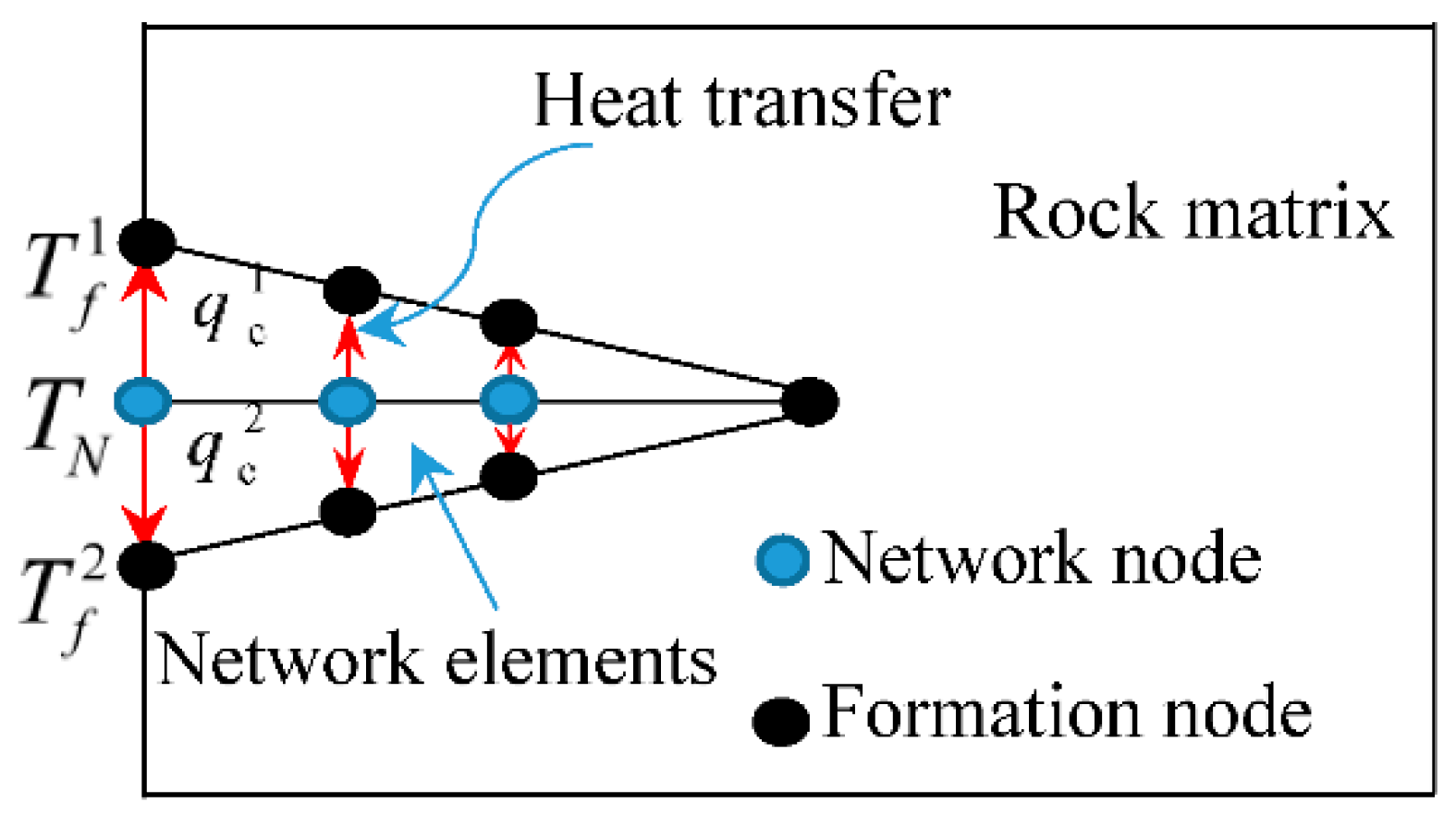
2.1. Governing Equations Considering Thermal Effects

In this study, the physical fields involved in the fracturing process of rock mass include temperature field, fluid field and solid field [32,33]. The matrix deformation governing equation of rock mass is:
L T ( σ α m p l ) + ρ B g = 0
where L is the differential operator, σ is the effective stress tensor, α is the Biot effective stress coefficient [34], m is the identity tensor, p l is the rock mass pore fluid pressure, ρ B is the saturated bulk density of rock mass and g is the gravity vector.
The following Equations (2) and (3) are the governing equations of seepage in the rock matrix and fluid flow in fractures, respectively:
d i v [ k μ l ( p l ρ l g ) ] = ( ϕ K l + α ϕ K s ) p l t + α ε v t
x [ k f r μ n ( p n ρ f n g ) ] = S f r d p n d t + α d Δ e ε d t
where k is the intrinsic permeability of the rock mass pore structure, μ l is viscosity of the pore liquid, K l is the bulk stiffness of the pore liquid, K s is solid skeleton stiffness, ε v is the bulk stiffness of the solid grains, t is the current moment, k f r is the fracture intrinsic permeability, μ n is viscosity of the fracturing fluid, p n is fluid pressure in the fracture, ρ f n is fluid density in the fracture, S f r is the parameter describing rock mass compressibility under fluid action and d Δ e ε d t is the aperture strain rate. It should be noted that the migration of gas in unconventional oil and gas and the chemical reaction are not involved in the fracturing process and may not be considered in this study. Some detailed contents, such as numerical implementation and the elastic constitutive equation, were omitted to avoid redundancy, as they can be found in the related references [32,33].
The governing equation of thermal effects between the rock mass matrix and fluid in pores and fractures is:
d i v [ k b T f ] = ρ b c b T f t + ρ f c f q f T f
where k b is the thermal conductivity coefficient, T f is fluid temperature, ρ b is volume density, c b is the specific heat coefficient, ρ f is fluid density, c f is the specific heat coefficient of fluid and q f is the Darcy fluid flux.
The differential governing Equations (1)–(4) of the solid deformation of the rock mass matrix, fluid flow in pores and fractures and thermal effects are discreted by the conventional finite element method. The form of heat transfer between element nodes is shown in Figure 1, and the temperature and heat flux at the nodes are:
q c 1 = α c ( T N ) ( T N T f 1 )
q c 2 = α c ( T N ) ( T N T f 2 )
where q c 1 and q c 2 are the heat flux values transmitted at the fracture plane node, T f 1 and T f 2 are the temperature values at the fracture plane node, T N is the temperature value of the node within the fracture and α c is the contact thermal conductivity. Temperature changes in rock masses with homogeneous medium-cause volume expansion and contraction:
Δ V / V = α T Δ T
where Δ T is the temperature change of the rock element, Δ V is the volume change, V is the initial volume and α T is the linear thermal expansion coefficient of the rock matrix.

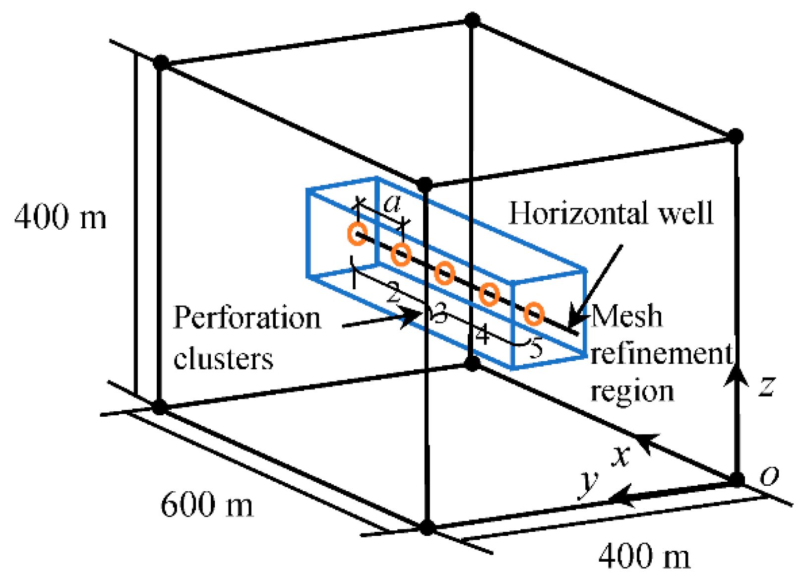
2.2. Three-Dimensional Numerical Model of Multistage Hydrofracturing under Different Cluster Spacing

The field-scale 3D model of multistage hydrofracturing of a horizontal well with multiple perforation clusters in a deep tight rock mass was established, as shown in Figure 2. There were five perforation cluster locations, sequentially numbered from 1 to 5. The basic physical parameters and perforation cluster spacing settings of the model are shown in Table 1, derived from the Shengli Oilfield in Shandong Province in China. According to the different initiation sequences of perforation clusters, the fracturing scheme was divided into sequential, simultaneous and alternate fracturing (duration time of each fracturing stage was 400 s), and Table 2 shows the duration and total time of each stage of different fracturing schemes. To form the initial stress field, the conventional and simple treatment technique is to apply the stress boundaries on the boundaries of the model. However, this technique has a disadvantage, that is, the local stress field around the boundary is not accurate, and the in situ stress in the domain away from the boundary is reliable. Another technique was used in the model. For the boundary conditions of the solid field, the treatment technique of this model was to use the displacement boundary conditions to fix the displacements on the six surfaces of the model and impose in situ stresses at each node in the finite element model as to form the in situ stress field at the initial stage; for the initial conditions of fluid and temperature fields, the pore pressure p s was set as 10 MPa and the temperature of surrounding rock mass was set as 60 °C. The model was analyzed by finite element-discrete element methods in the program package ELFEN [35]. For the mesh generation, the mesh refinement technology was adopted to ensure the reliability of fracture propagation [33].
In order to illustrate the influence of initial in situ stress on fracture propagation, some results of fracture propagation over a long duration time were added. A testing model with the coincident physical parameters and in situ stress conditions as the numerical model of multistage hydrofracturing was established. The model only set up one perforation and carried out hydrofracturing to study the behavior of in situ stress affecting fracture propagation. In order to fully show that the in situ stress affects the spatial propagation behavior of the fracturing fracture, the testing model continued to inject fracturing fluid up to 810 s after 410 s of the injection time (410 s was the first stage of multistage hydrofracturing, including the first 10 s of the initial balance stage). It can be seen that when the time was 410 s, as shown in Figure 3a, the fracture propagated straightly, which was affected by the initial straight perforation direction (the minimum in situ stress direction); as the time increased to 810 s, as shown in Figure 3b, the fracture began to deflect towards the maximum horizontal in situ stress, and the fracture had a relatively large deflection angle, forming a spatially deflected fracture. The above results show that the in situ stress state is an influencing factor of fracture deflection, and the deflection behavior becomes more and more drastic when the fracture propagates to a certain extent (such as 810 s in the testing model). In this study, the duration time of injection of each fracturing stage was not set very long, in order to reduce the deflection of fracture propagation affected by initial in situ stress, and only focus on the influence of perforation spacing and initiation sequence.

3. Results and Analysis

The main research purposes of this study were not to develop a novel numerical method for hydrofracturing, but to study the fracture deflection behaviors and mechanisms under the background of multistage hydrofracturing engineering of unconventional oil and gas exploitation. This section discusses the related results and two innovations of this study:
(a)
First, a 3D numerical model of multistage hydrofracturing, considering the coupling of multiple physical fields, was established; the temperature effects were considered in the simulation of the hydraulic fracturing process in some of the literature, but the influence of temperature effects was still not considered in previous research on the spatial deflection of multiple hydraulic fractures. These results are reliably derived below.
(b)
Second, in order to address the evaluation and control of the fracture network in hydrofracturing engineering, the spatial deflection behaviors of 3D fractures in hydrofracturing under varying perforation cluster spacing and fracture initiation sequences were studied. An innovation of this study was to analyze the interaction in fracture propagation by using the evolution process of the shear stress field compared with the common analysis based on the principal stresses.

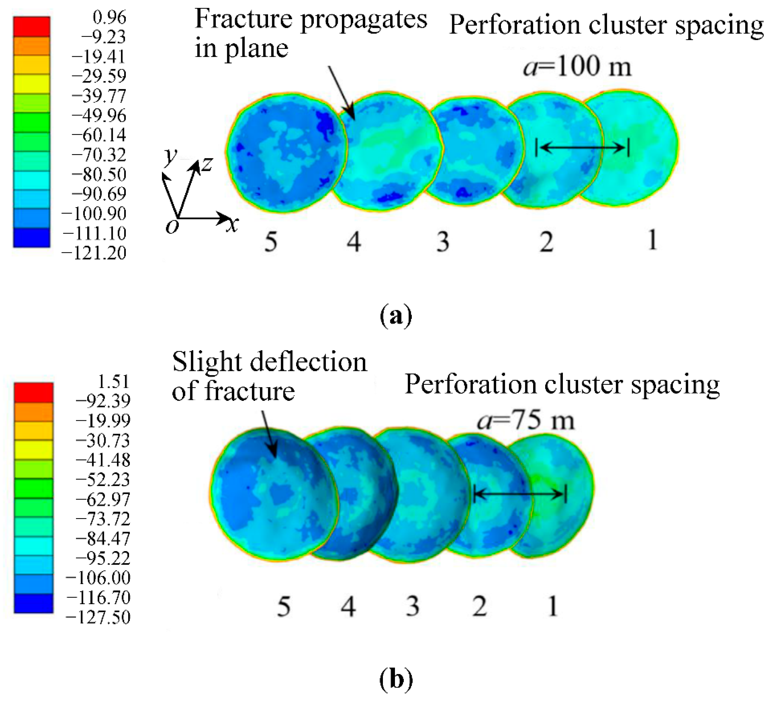
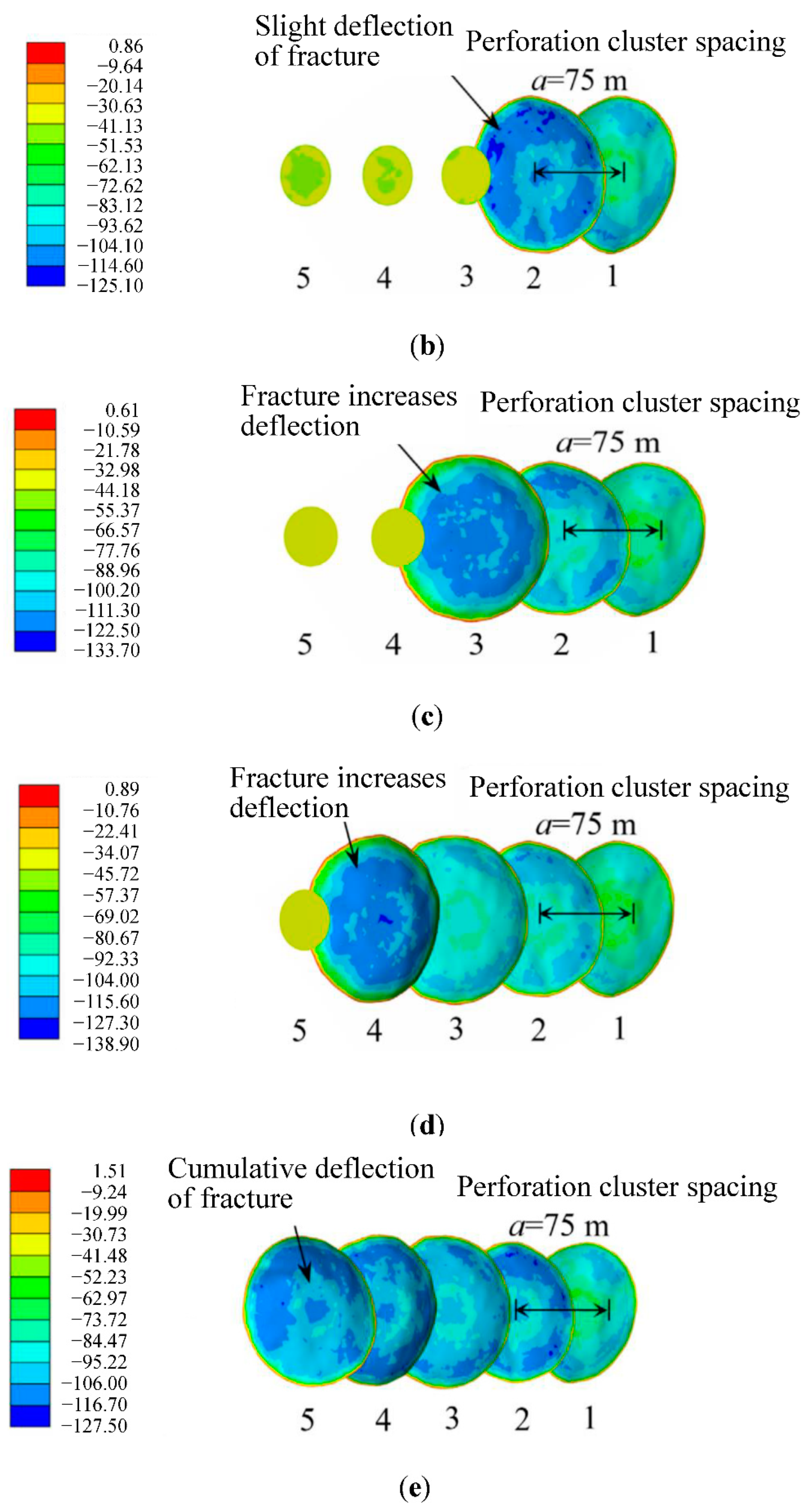
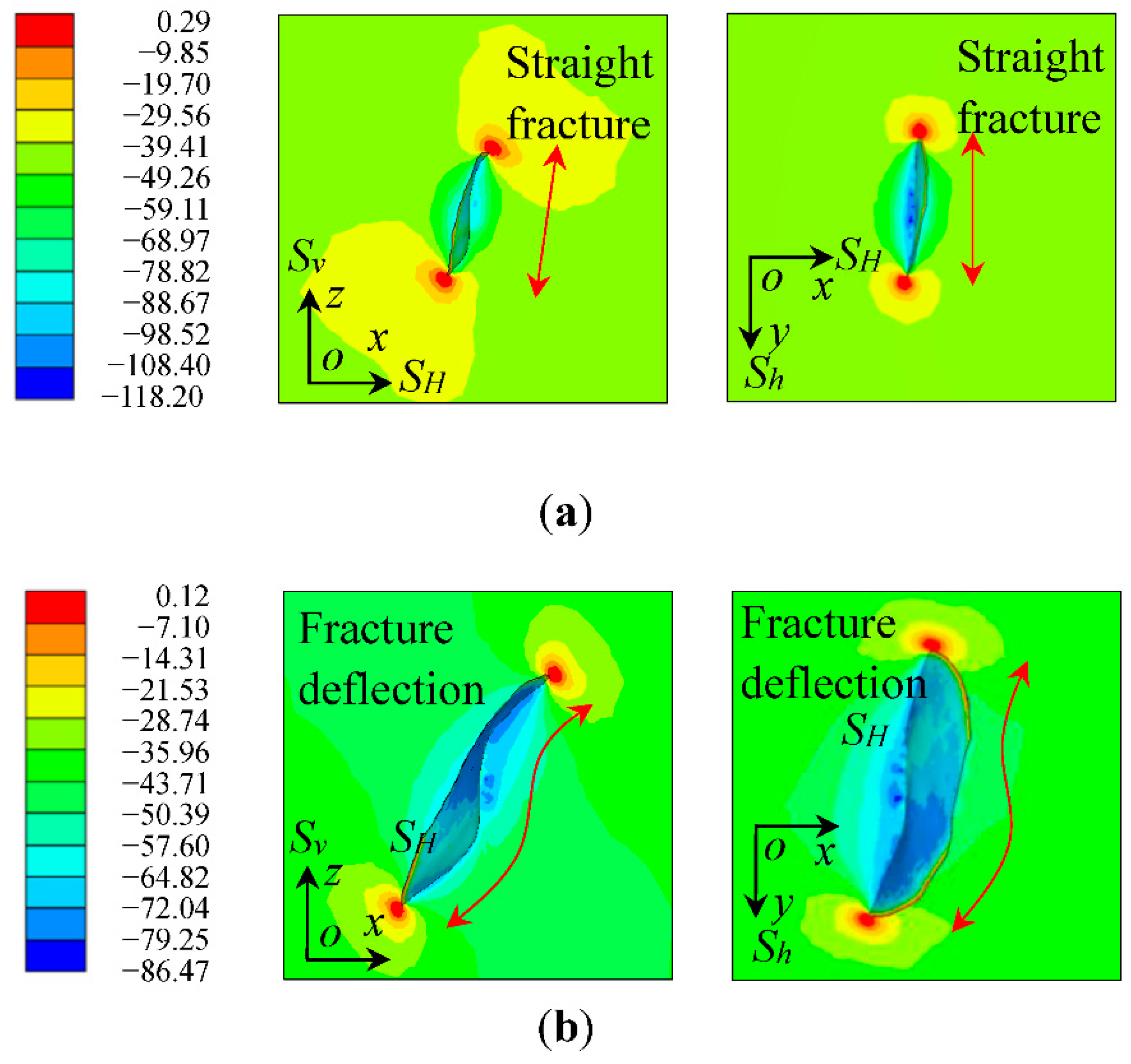
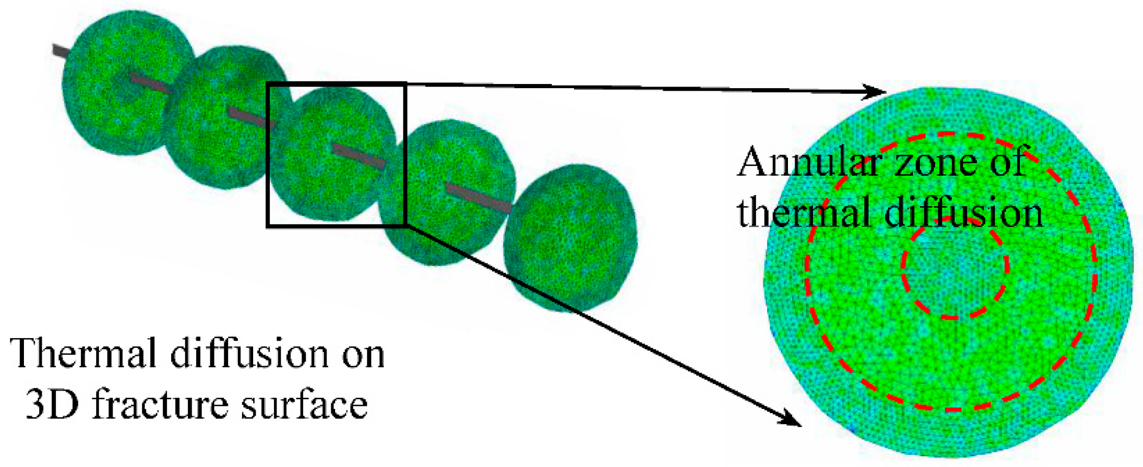
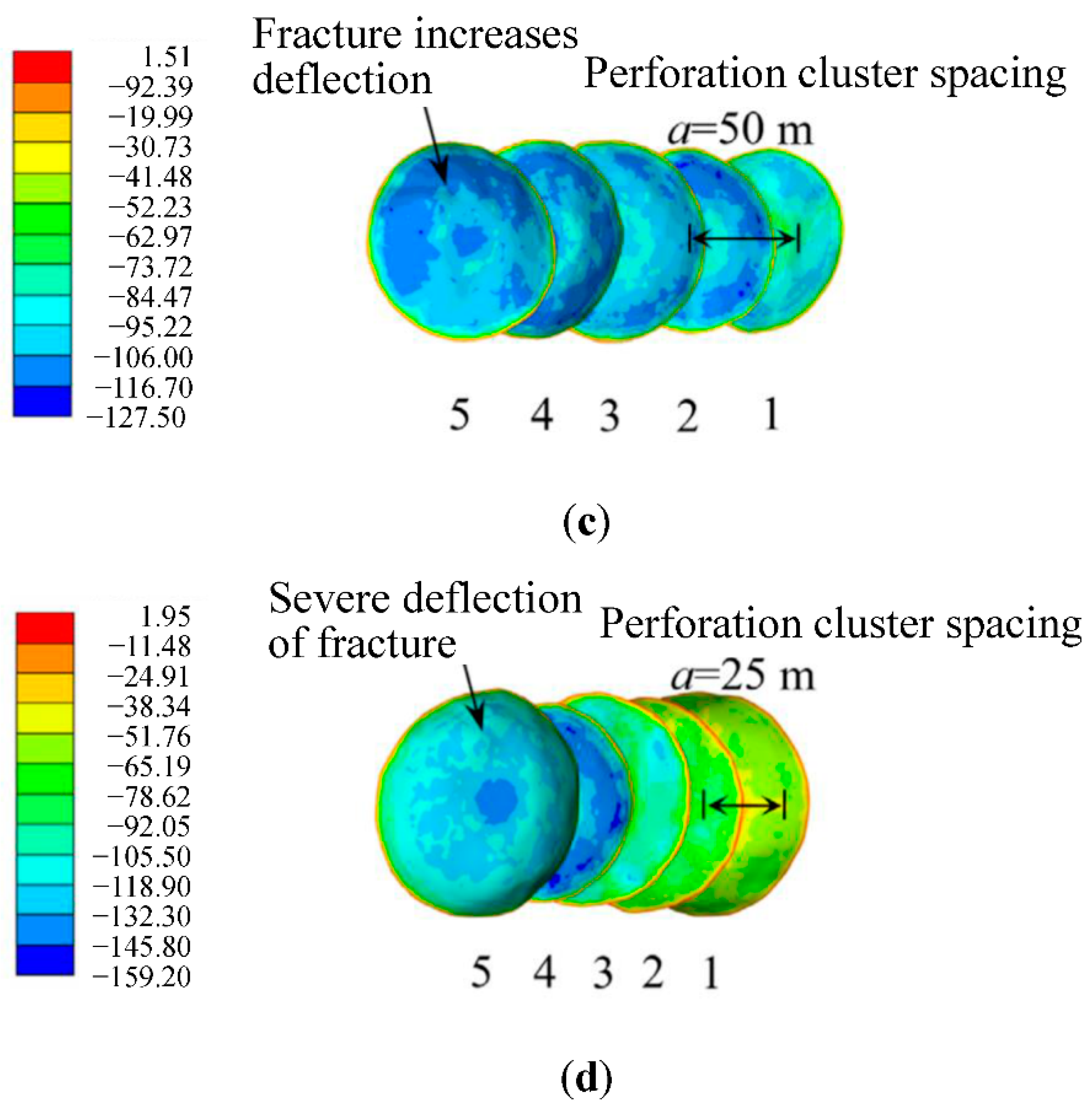
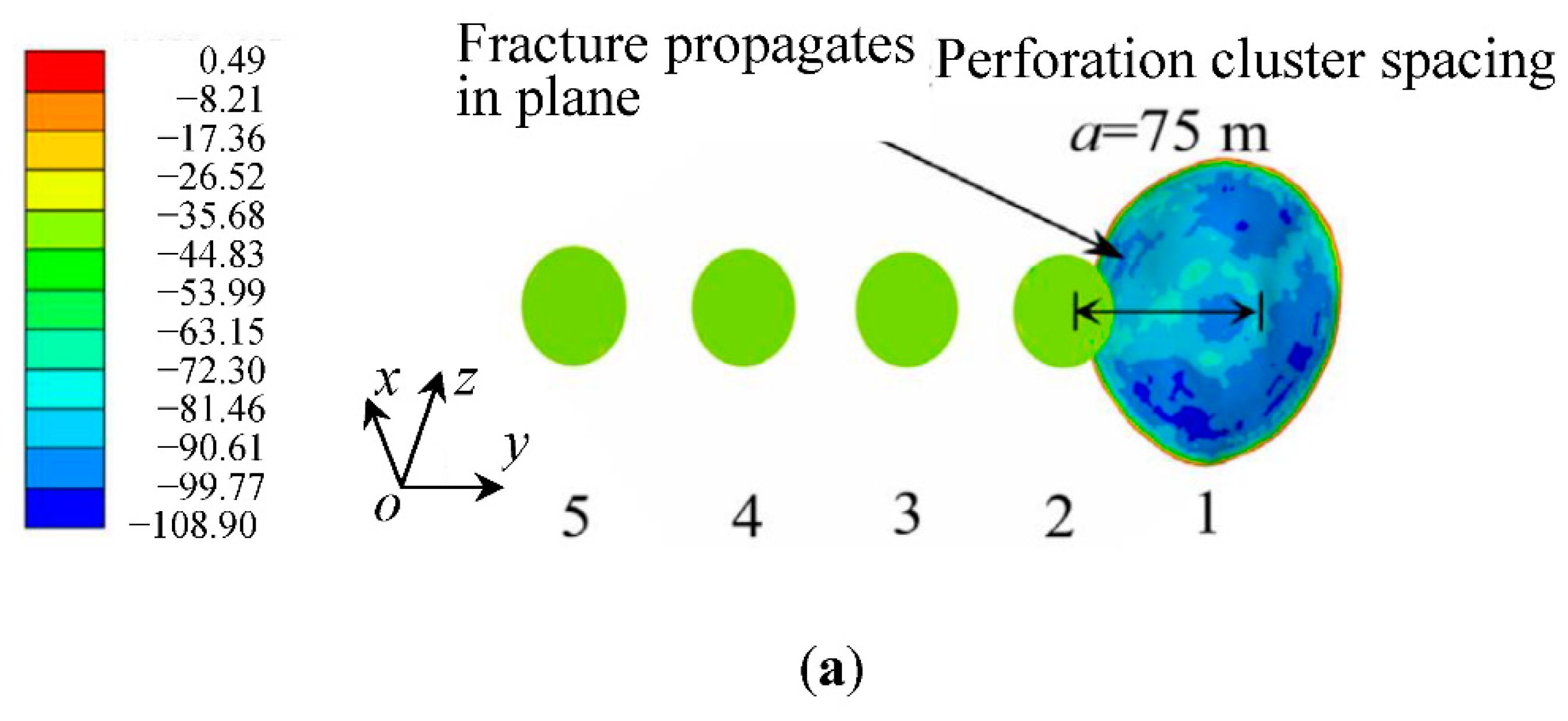
3.1. Thermal Effects and Deflection Behaviors of Multiple Hydraulic Fractures

Figure 4 shows the thermal diffusion behavior in the fracture region. The temperature gradient between the fracturing fluid and rock matrix caused thermal diffusion on the annular region of the 3D fracture surface. The temperature of the fracturing fluid in the wellbore was 20 °C and the temperature of the surrounding rock mass was 60 °C; the annular zone shows the thermal diffusion. By comparing the results of fracture propagation, it was found that the fracture volume and area obtained by fracture propagation simulation considering thermal effects were both larger than those without thermal effects, and ignoring the thermal effect underestimates the propagation of fracture networks.
Figure 5 shows the final fracture morphology and stress field results under different perforation cluster spacing in sequential fracturing. When the cluster spacing was large, the fractures were nearly parallel and stable. With the narrowing of the perforation cluster spacing, the mutual interference between fractures gradually increased, and the deflection intensified from the second fracture. The spacing of perforation clusters is an important factor affecting the deflection behavior of 3D fractures. The positive value of the color bar in the figure indicates tensile stress, whereas the negative value indicates compressive stress. The maximum value of positive tension shown in Figure 5d was 1.95 MPa, which was less than 5.26 MPa of the tensile strength of the rock mass as shown in Table 1; thus, it did not met the requirements of the fracture criterion (in the Appendix A section) of the rock mass.
Figure 6 shows the results of fracture propagation at each stage of sequential fracturing. The first fracture propagated in space close to the plane because there was no interference from other fractures. The second fracture appeared with a slight deflection in space due to the disturbance of the first fracture. The third fracture was disturbed by the first and second fractures and the deflection was intensified. Cumulative deflection occurred in the fracturing process of the remaining perforation clusters, and the fractures were all tilted in the same direction.

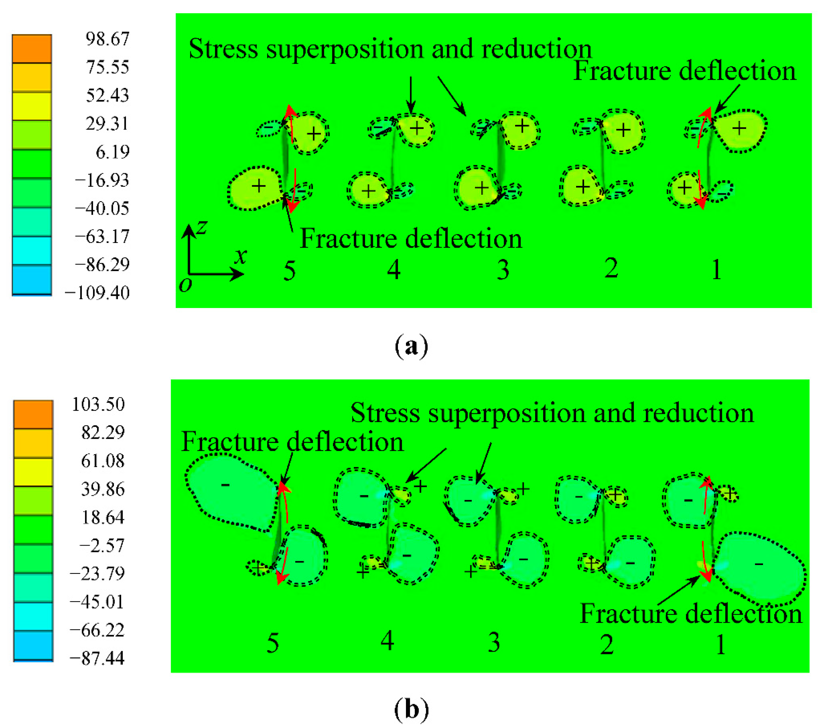
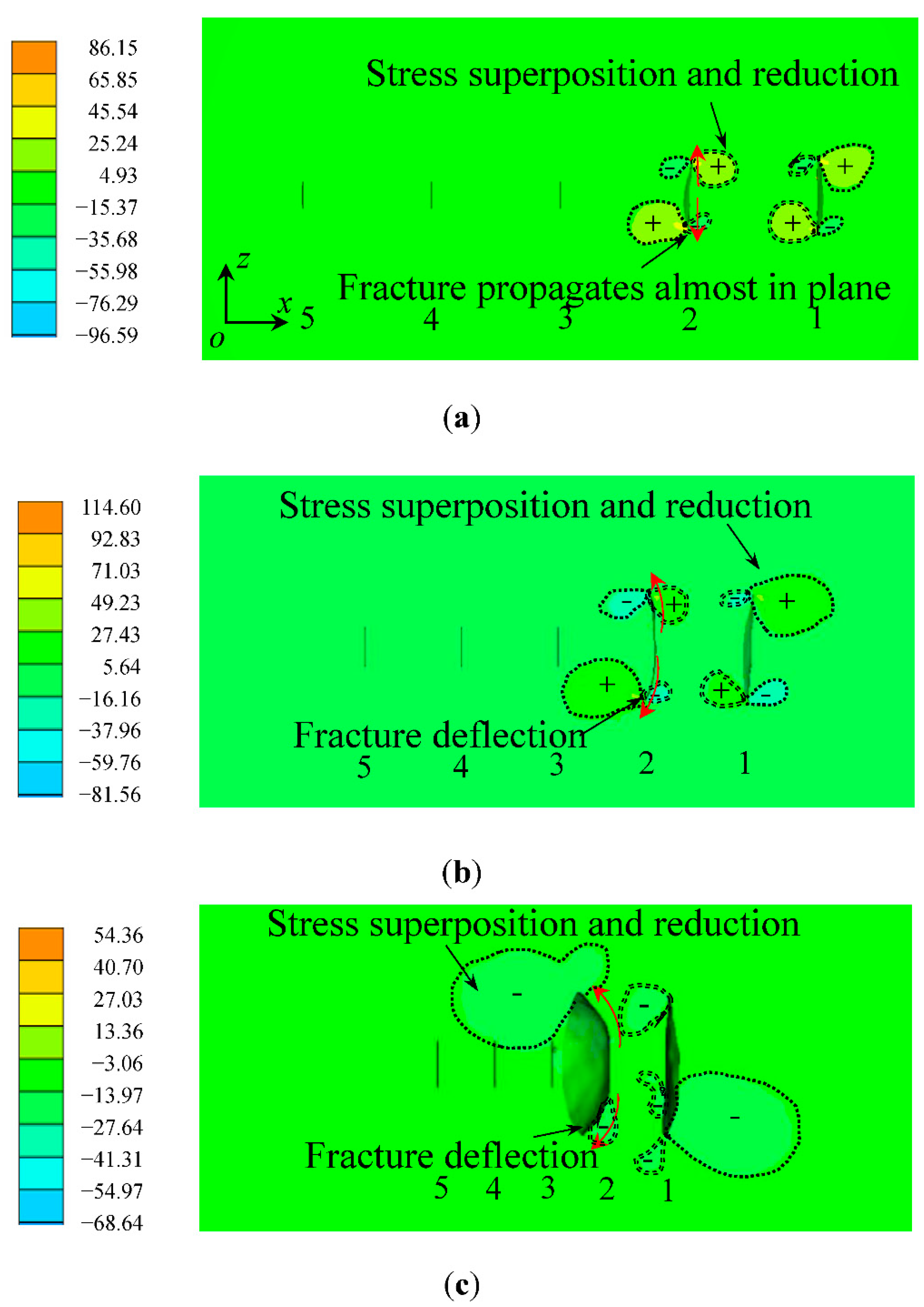
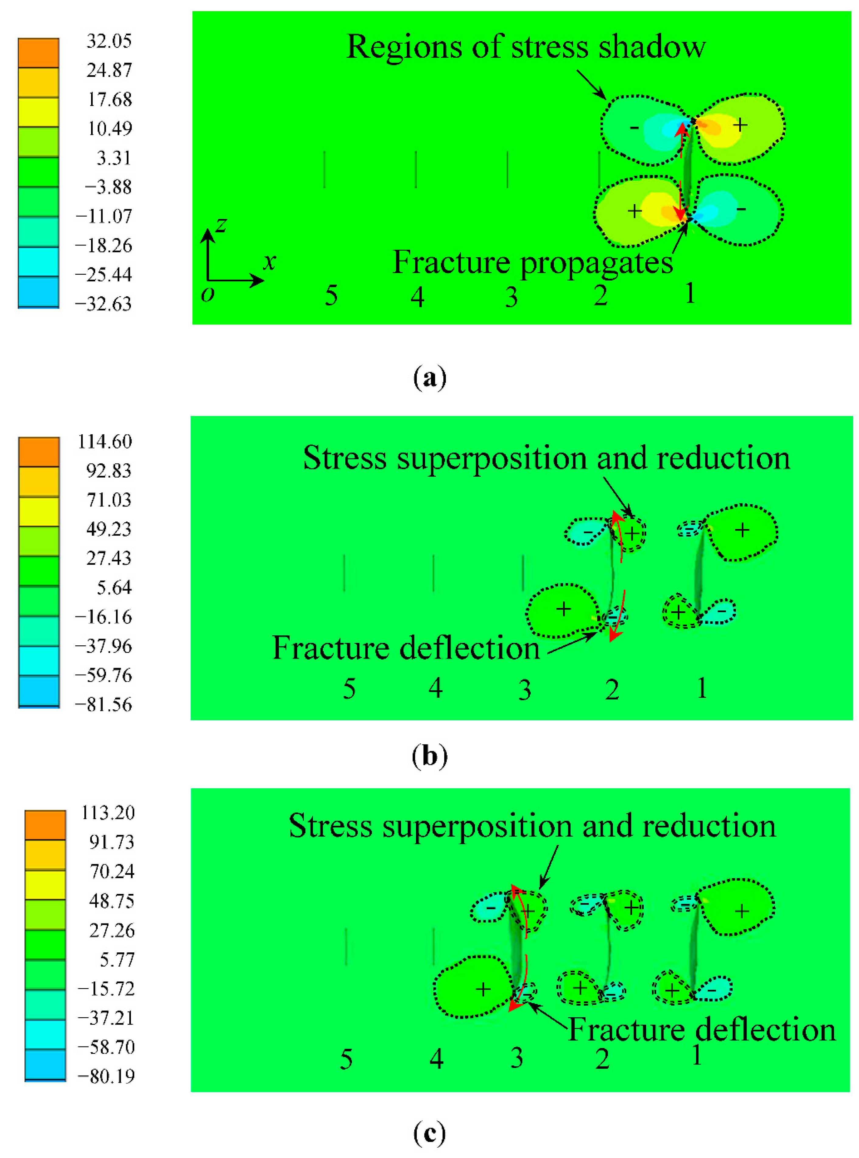
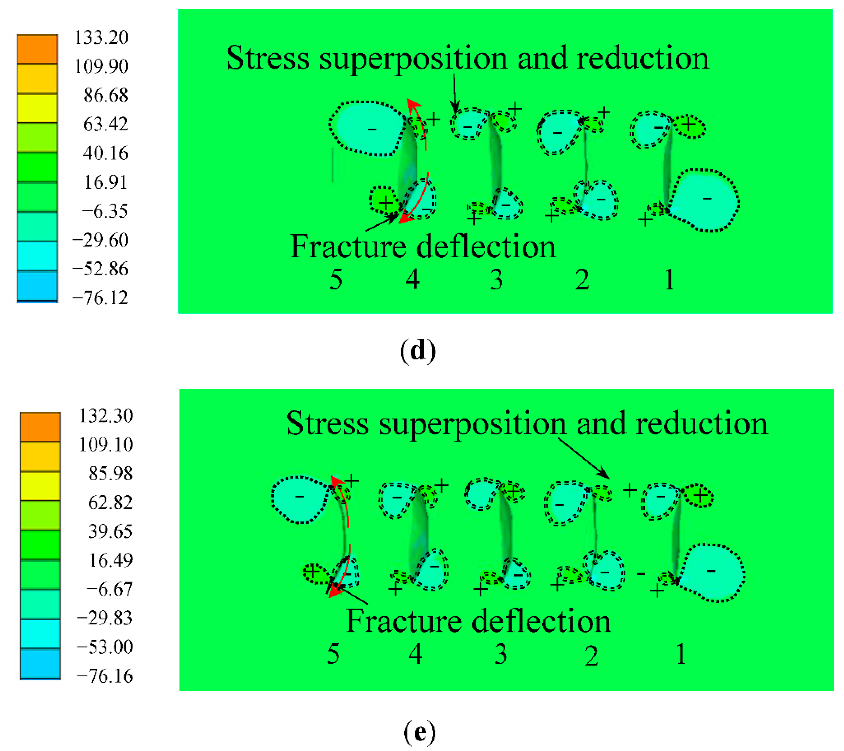
3.2. Shear Stress Disturbance under Different Cluster Spacing

The greater the stress value in the stress concentration area, the more prone the fracture is to propagate. Therefore, the fracture propagation can be predicted by observing the stress field. In this study, the fracture propagation and deflection were studied by observing the change in the size of the shear stress area. Due to the basis that the shear stress distributions around the fracture can effectively reflect the propagation behaviors, a comparison of shear stress disturbances under hydro-mechanical (HM) coupling and THM coupling is shown in Figure 7. The shear stresses are derived results on the cross section of the 3D model. The upper left side of the fracture had positive shear stress and the right side had negative shear stress. At the same time, the fracture had negative shear stress at the lower left and positive shear stress at the right. These positive and negative signs were used to distinguish the positive and negative types of shear stress around the fracture tips. The superposition of different positive and negative shear stresses arose, and this superposition is like the cancellation process of the sum of positive and negative numbers. Further, the deflection of fractures caused by these superposition effects (stress shadow effects) were analyzed. By comparing Figure 7a,b, it was found that the shear stress field area around the fracture was larger when the thermal effect was considered, and the shear stress disturbance caused by the weakening of shear stress superposition was stronger. Therefore, thermal diffusion has a great influence on the shear stress field disturbance around the fracture, which needs to be considered. It should be noted that the shear stress reached a larger value, which may be not considered to generate fractures, because the shear stress was not used as the judgment basis of fracture criterion.
Figure 8 shows the shear stress disturbance of sequential fracturing at different spacings of perforation clusters. At 100 m of perforation cluster spacing, the stress field around the first fracture and the second fracture was slightly superimposed and reduced, and the fracture propagation was less affected by the stress shadow effect. At 50 m of perforation cluster spacing, the positive and negative shear stress areas near the first fracture and the second fracture superimposed obviously, resulting in the shear stress field on the right side of the second fracture being obviously weakened and the fracture deflected to the left side of the larger shear stress field. At 25 m of perforation cluster spacing, the stress field around the first fracture and the second fracture was seriously superimposed and reduced, resulting in the shear stress field on the right side of fracture 2 being obviously weakened, and the deflection degree to the larger shear stress area on the left side became larger.
Figure 9 shows the shear stress disturbance of sequential fracturing. In the first stage, the stress around the first fracture was almost symmetrical and the fracture propagated in a plane direction. In the second stage, the second fracture began to propagate, and the stress shadow area around fracture 1 obviously covered the shear stress area caused by fracture 2, resulting in the superposition and weakening of the shear stress field caused by the first two fractures. The shear stress on the right of fracture 2 was significantly weakened, which caused fracture 2 to expand and deflect towards the larger stress area on the left. Each remaining fracture caused shear stress to superimpose and decrease around them, with more pressure on the area to the left of the fracture causing the fracture to deflect to the left. The fracture deflection gradually intensified, which was due to the formation of large stress accumulation around the fracture and serious fracture deflection.

4. Conclusions

The conclusions of this study can be summarized as follows:
(1)
The thermal effects were considered and the effect of perforation cluster spacing on the deflection behavior of hydraulic fracture and shear stress disturbance around the fracture was analyzed. The thermal effects may increase the shear stress around the fracture and increase stress disturbance. Ignoring the thermal effects underestimates the propagation of fracture networks. To investigate the mechanisms of thermal effects on stress variation, some microscale modelling and analysis need to be studied in the next work.
(2)
The decrease in the spacing of multiple perforation clusters in horizontal wells aggravates the mutual interference between fractures and leads to the increase in fracture deflection. The spacing of perforation clusters is an important factor affecting deflection of 3D hydraulic fractures.
(3)
As the spacing of perforation clusters decreases, the superposition area of shear stress field increases and the shear stress disturbance becomes stronger, thus increasing the mutual interference between fractures. In sequential fracturing, as fractures are fractured one by one, the superposition and reduction of shear stress fields around fractures accumulate, leading to the gradual intensification of subsequent fracture deflection.
The propagation behaviors and morphology of hydraulic fractures are related to the oil and gas production of the reservoir. Comprehensive research should study the control factors of hydraulic fractures, master the mechanisms of fracture deflection, control and optimize the fracture network and, finally, improve the reservoir production. This study mainly analyzed and compared the deflection of hydraulic fractures and shear stress disturbance considering thermal effects: the comparison shows that the thermal diffusion effect has an important influence on the fracture propagation in hydrofracturing; the influence of perforation cluster spacing on multiple fractures propagation was also analyzed based on the fracture interaction and shear stress field evolution. However, the oil and gas production of the reservoir after fracture propagation involves more complex fluid backflow and oil and gas production in the reservoir, which is the next source of content to research in the future.

Author Contributions

N.L.: methodology, software, formal analysis, investigation, data curation, writing—original draft preparation and visualization. Y.W.: conceptualization, methodology, resources, writing—reviewing and editing, supervision, project administration and funding acquisition. All authors have read and agreed to the published version of the manuscript.

Funding

This research was funded by the National Natural Science Foundation of China (grants 41877275 and 51608301), Beijing Natural Science Foundation (grant L212016), Yue Qi Young Scholar Project Foundation of China University of Mining and Technology, Beijing (grant 2019QN14), Fundamental Research Funds for the Central Universities, Ministry of Education of China (grant 2019QL02), Teaching Reform and Research Projects of Undergraduate Education of China University of Mining and Technology, Beijing (grants J210613, J200709, and J190701), and the Open Fund of Tianjin Key Lab of Soft Soil Charac-teristics and Engineering Environment (grant 2017SCEEKL003).

Institutional Review Board Statement

Not applicable.

Informed Consent Statement

Not applicable.

Data Availability Statement

Not applicable.

Conflicts of Interest

The authors declare no conflict of interest.

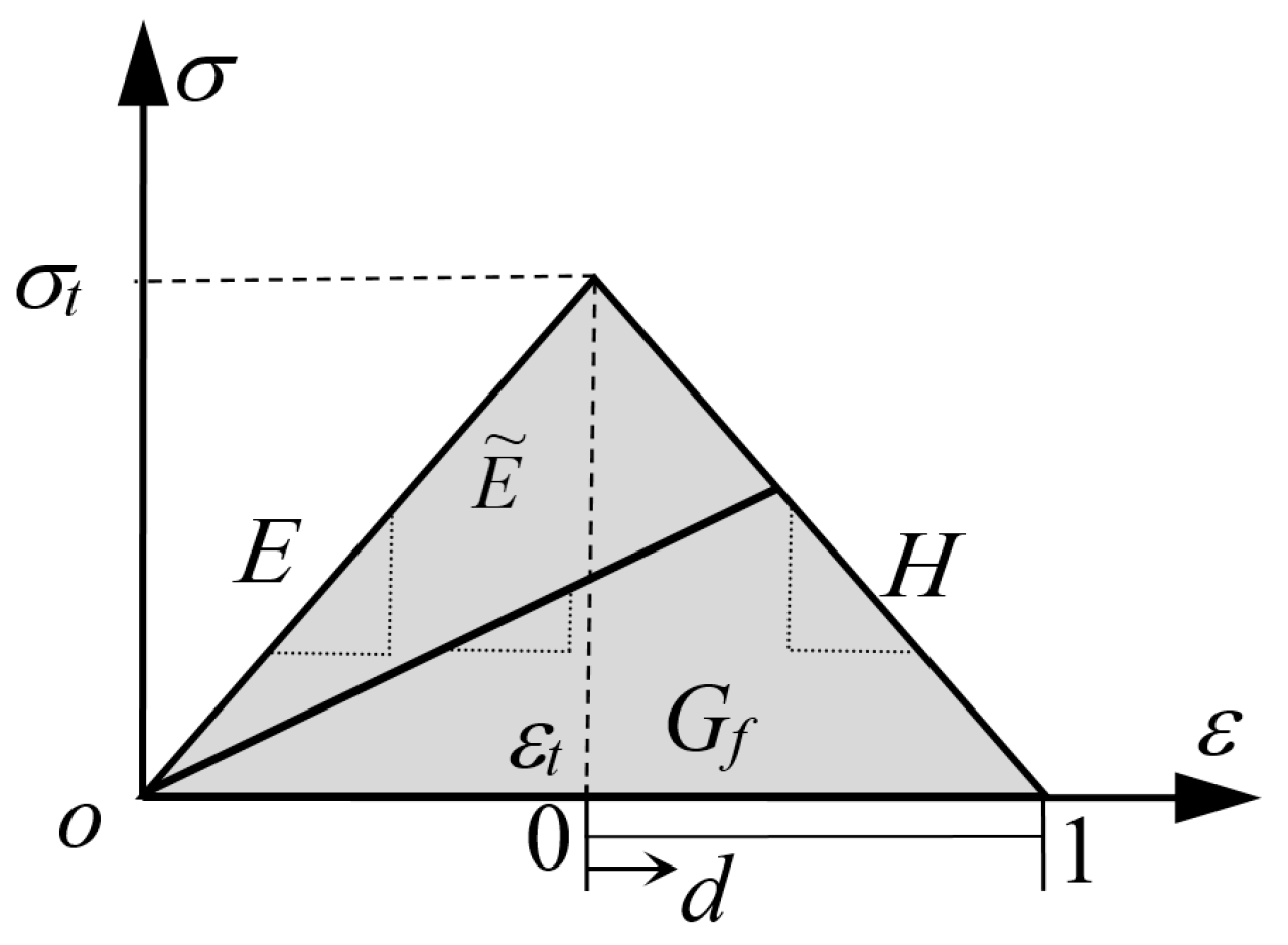
Appendix A. Fracture Criteria

To simulate damage evolution and fracture propagation processes, continuous damage and fracture criteria in the form of energy were introduced [32,33]. The tensile strength and fracture energy of the element are recorded as σ t and G f , respectively; when the maximum principal tensile stress reaches σ t , the element begins to damage ( d = 0 ), and when the principal tensile stress is 0, the element damage reaches the maximum ( d = 1 ). The area enclosed by the stress-strain curve and the x axis is the fracture energy G f . Complete damage reflects failure behavior; whereas fracture is predicted at failure, solids break apart at nodes. The fracture criterion is implemented in a finite element-discrete element program.
Figure A1. Relationship of stress-stain and damage analysis.
Energies 15 04888 g0a1
In the non-damaged linear elastic stage, the slope of the stress-strain curve is the elastic modulus E. In the damage stage, the slope H and elastic modulus E ˜ of the stress-strain curve considering the current damage are:
H = σ t 2 C l 2 G f
E ˜ = E ( 1 d )  
Among them, σ t is the tensile strength, G f is the fracture energy, C l is the characteristic length of the element, d is the damage variable and E is the elastic modulus in the elastic stage.

References

  1. Olayiwola, S.O.; Rahman, M.M. Optimizing economic number of transverse fractures in horizontal well: A systematic design for maximum tight gas recovery. Adv. Pet. Explor. Dev. 2017, 13, 32–42. [Google Scholar] [CrossRef]
  2. Kohl, T.; Evansi, K.F.; Hopkirk, R.J.; Rybach, L. Coupled hydraulic, thermal and mechanical considerations for the simulation of hot dry rock reservoirs. Geothermics 1995, 24, 345–359. [Google Scholar] [CrossRef]
  3. Ghassemi, A.; Zhou, X. A three-dimensional thermo-poroelastic model for fracture response to injection/extraction in enhanced geothermal system. Geothermics 2011, 40, 39–49. [Google Scholar] [CrossRef]
  4. Zhao, Y.; Feng, Z.; Yang, D.; Liang, W. THM (Thermo-hydro-mechanical) coupled mathematical model of fractured media and numerical simulation of a 3D enhanced geothermal system at 573 K and buried depth 6000–7000 M. Energy 2015, 82, 193–205. [Google Scholar] [CrossRef]
  5. Li, S.B.; Li, X.; Zhang, D.X. A fully coupled thermo-hydro-mechanical, three-dimensional model for hydraulic stimulation treatments. J. Nat. Gas Sci. Eng. 2016, 34, 64–84. [Google Scholar] [CrossRef]
  6. Feng, W.; Were, P.; Li, M.; Hou, Z.; Zhou, L. Numerical study on hydraulic fracturing in tight gas formation in consideration of thermal effects and THM coupled processes. J. Pet. Sci. Eng. 2016, 146, 241–254. [Google Scholar] [CrossRef]
  7. Wong, S.W.; Geilikman, M.; Xu, G. Interaction of multiple hydraulic fractures in horizontal wells. In Proceedings of the SPE Unconventional Gas Conference and Exhibition, Muscat, Oman, 28–30 January 2013. [Google Scholar] [CrossRef] [Green Version]
  8. Manriquez, A.L.; Sepehrnoori, K.; Cortes, A. A novel approach to quantify reservoir pressure along the horizontal section and to optimize multistage treatments and spacing between hydraulic fractures. J. Pet. Sci. Eng. 2017, 149, 579–590. [Google Scholar] [CrossRef]
  9. Bažant, Z.P.; Salviato, M.; Chau, V.T.; Visnawathan, H.; Zubelewicz, A. Why fracking works. J. Appl. Mech. 2014, 81, 101010. [Google Scholar] [CrossRef]
  10. Zhang, X.; Jeffrey, R.G. Fluid-driven multiple fracture growth from a permeable bedding plane intersected by an ascending hydraulic fracture. J. Geophys. Res. Solid Earth 2012, 117, 1–12. [Google Scholar] [CrossRef]
  11. Cipolla, C.L.; Lolon, E.; Mayerhofer, M.J.; Warpinski, N.R. Fracture design considerations in horizontal wells drilled in unconventional gas reservoirs. In Proceedings of the SPE Hydraulic Fracturing Technology Conference, The Woodlands, TX, USA, 19–21 January 2009. [Google Scholar] [CrossRef]
  12. Wang, H.Y. Numerical investigation of fracture spacing and sequencing effects on multiple hydraulic fracture interference and coalescence in brittle and ductile reservoir rocks. Eng. Fract. Mech. 2016, 157, 107–124. [Google Scholar] [CrossRef]
  13. Luo, S.G.; Zhao, Y.L.; Zhang, L.H.; Chen, Z.X.; Zhang, X.Y. Integrated simulation for hydraulic fracturing, productivity prediction, and optimization in tight conglomerate reservoirs. Energy Fuels 2021, 35, 14658–14670. [Google Scholar] [CrossRef]
  14. Gutierrez, R.; Sanchez, E.; Roehl, D.; Romanel, C. XFEM modeling of stress shadowing in multiple hydraulic fractures in multi-layered formations. J. Nat. Gas Sci. Eng. 2019, 70, 102950. [Google Scholar] [CrossRef]
  15. Li, J.X.; Xiao, W.; Hao, G.Z.; Dong, S.M.; Hua, W.; Li, X.L. Comparison of different hydraulic fracturing scenarios in horizontal wells using XFEM based on the cohesive zone method. Energies 2019, 12, 1232. [Google Scholar] [CrossRef] [Green Version]
  16. Liu, X.Q.; Rasouli, V.; Guo, T.; Qu, Z.Q.; Sun, Y.; Damjanac, B. Numerical simulation of stress shadow in multiple cluster hydraulic fracturing in horizontal wells based on lattice modelling. Eng. Fract. Mech. 2020, 238, 107278. [Google Scholar] [CrossRef]
  17. Wang, Y.L.; Liu, X.G. Stress-dependent unstable dynamic propagation of three-dimensional multiple hydraulic fractures with improved fracturing sequences in heterogeneous reservoirs: Numerical cases study via poroelastic effective medium model. Energy Fuels 2021, 35, 18543–18562. [Google Scholar] [CrossRef]
  18. He, Q.; Suorineni, F.T.; Ma, T.; Oh, J. Effect of discontinuity stress shadows on hydraulic fracture re-orientation. Int. J. Rock Mech. Min. Sci. 2017, 91, 179–194. [Google Scholar] [CrossRef]
  19. Sobhaniaragh, B.; Mansur, W.J.; Peters, F.C. The role of stress interference in hydraulic fracturing of horizontal wells. Int. J. Rock Mech. Min. Sci. 2018, 106, 153–164. [Google Scholar] [CrossRef]
  20. Yoon, J.S.; Zimmermann, G.; Zang, A. Numerical investigation on stress shadowing in fluid injection-induced fracture propagation in naturally fractured geothermal reservoirs. Rock Mech. Rock Eng. 2015, 48, 1439–1454. [Google Scholar] [CrossRef]
  21. Cheng, W.; Gao, H.; Jin, Y.; Chen, M.; Jiang, G.S. A study to assess the stress interaction of propped hydraulic fracture on the geometry of sequential fractures in a horizontal well. J. Nat. Gas Sci. Eng. 2016, 37, 69–84. [Google Scholar] [CrossRef]
  22. Damjanac, B.; Maxwell, S.; Pirayehgar, A.; Torres, M. Numerical study of stress shadowing effect on fracture initiation and interaction between perforation clusters. In Proceedings of the SPE/AAPG/SEG Unconventional Resources Technology Conference, Houston, TX, USA, 23–25 July 2018. [Google Scholar] [CrossRef]
  23. Sesetty, V.; Ghassemi, A. Numerical simulation of sequential and simultaneous hydraulic fracturing. In Proceedings of the ISRM International Conference for Effective and Sustainable Hydraulic Fracturing, Brisbane, Australia, 20–22 May 2013. [Google Scholar] [CrossRef] [Green Version]
  24. Haddad, M.; Sepehrnoori, K. XFEM-based CZM for the simulation of 3D multiple-cluster hydraulic fracturing in quasi-brittle shale formations. Rock Mech. Rock Eng. 2016, 49, 4731–4748. [Google Scholar] [CrossRef]
  25. Tang, P.F.; Wei, X.; Liu, Y.; Zhang, Y.B.; Zhang, K.; Yang, C.C.; Li, C.R. Study on fracture interference for volume fracturing. In Proceedings of the International Field Exploration and Development Conference, Xi’an, China, 16–18 October 2019; Springer: Singapore, 2019; pp. 2894–2909. [Google Scholar] [CrossRef]
  26. Wang, X.L.; Liu, C.; Wang, H.; Liu, H.; Wu, H.A. Comparison of consecutive and alternate hydraulic fracturing in horizontal wells using XFEM-based cohesive zone method. J. Pet. Sci. Eng. 2016, 143, 14–25. [Google Scholar] [CrossRef]
  27. Paluszny, A.; Tang, X.H.; Zimmerman, R.W. Fracture and impulse based finite-discrete element modeling of fragmentation. Comput. Mech. 2013, 52, 1071–1084. [Google Scholar] [CrossRef]
  28. Taghichian, A.; Zaman, M.; Devegowda, D. Stress shadow size and aperture of hydraulic fractures in unconventional shales. J. Pet. Sci. Eng. 2014, 124, 209–221. [Google Scholar] [CrossRef]
  29. Kresse, O.; Weng, X.; Gu, H.; Wu, R. Numerical modeling of hydraulic fractures interaction in complex naturally fractured formations. Rock Mech. Rock Eng. 2013, 46, 555–568. [Google Scholar] [CrossRef]
  30. Kumar, D.; Ghassemi, A. A three-dimensional analysis of simultaneous and sequential fracturing of horizontal wells. J. Pet. Sci. Eng. 2016, 146, 1006–1025. [Google Scholar] [CrossRef]
  31. Wang, Y.L.; Liu, N.N.; Zhang, X.; Liu, X.G.; Wang, J. Influences on unstable hydraulic fractures: Propagation of adjacent multiple perforations and bedded interfaces in multilayered reservoir via FE-DE model. Eng. Comput. 2021, 39, 1407–1431. [Google Scholar] [CrossRef]
  32. Wang, Y.L.; Ju, Y.; Chen, J.L.; Song, J.X. Adaptive finite element–discrete element analysis for the multistage supercritical CO2 fracturing of horizontal wells in tight reservoirs considering pre-existing fractures and thermal-hydro-mechanical coupling. J. Nat. Gas Sci. Eng. 2019, 61, 251–269. [Google Scholar] [CrossRef]
  33. Wang, Y.L. Adaptive finite element–discrete element analysis for stratal movement and microseismic behaviours induced by multistage propagation of three-dimensional multiple hydraulic fractures. Eng. Comput. 2020, 38, 2781–2809. [Google Scholar] [CrossRef]
  34. Hampton, J.; CBoitnott, G.N. The misnomer of “Effective Stress” and its relation to Biot Coefficients. In Proceedings of the 52nd US Rock Mechanics/Geomechanics Symposium, Seattle, WA, USA, 17–20 July 2018; p. ARMA-2018-1130. [Google Scholar]
  35. ELFEN TGR User and Theory Manual, Rockfield Software Ltd.: Swansea, UK, 2016.
Figure 1. Heat transfer between finite element nodes in formation and network.
Energies 15 04888 g001
Figure 2. Initial geometric field-scale 3D model of multistage hydrofracturing of horizontal well with multiple perforation clusters.
Energies 15 04888 g002
Figure 3. Influence of in situ stresses on spatial deflection of fracture and the first principal stress (MPa) in single perforation. (a) Fracture propagation on cross section, t = 410 s. (b) Fracture deflection in the direction of maximum in situ stress on cross section, t = 810 s.
Energies 15 04888 g003
Figure 4. Thermal effects around fracture domains.
Energies 15 04888 g004
Figure 5. Final morphology of fracture network and the first principal stress (MPa) in sequential fracturing. (a) Perforation cluster spacing a = 100 m. (b) Perforation cluster spacing a = 75 m. (c) Perforation cluster spacing a = 50 m. (d) Perforation cluster spacing a = 25 m.
Energies 15 04888 g005aEnergies 15 04888 g005b
Figure 6. Dynamic propagation of fracture network and the first principal stress (MPa) in sequential fracturing. (a) First stage, t = 410 s. (b) Second stage, t = 810 s. (c) Third stage, t = 1210 s. (d) Fourth stage, t = 1610 s. (e) Fifth stage, t = 2010 s.
Energies 15 04888 g006aEnergies 15 04888 g006b
Figure 7. Disturbance of shear stress σ z x (MPa) in simultaneous fracturing for a cluster spacing of 75 m (“+” represents positive shear stress and “−” represents negative shear stress). (a) HM coupling. (b) THM coupling.
Energies 15 04888 g007
Figure 8. Disturbance of shear stress σ z x (MPa) in sequential fracturing for different cluster spacing. (a) Perforation cluster spacing a = 100 m. (b) Perforation cluster spacing a = 50 m. (c) Perforation cluster spacing a = 25 m.
Energies 15 04888 g008
Figure 9. Disturbance of shear stress σ z x (MPa) in sequential fracturing. (a) First stage, t = 410 s. (b) Second stage, t = 810 s. (c) Third stage, t = 1210 s. (d) Fourth stage, t = 1610 s. (e) Fifth stage, t = 2010 s.
Energies 15 04888 g009aEnergies 15 04888 g009b
Table 1. Basic physical parameters of the model.
ParametersValue
 Vertical in situ stress (z direction) S v (MPa)40
 Horizontal minimum in situ stress (y direction) S h (MPa)46
 Horizontal maximum in situ stress (x direction) S H (MPa)60
 Fluid injection rate Q (m3/s)0.5
 Pore pressure p s (MPa)10
 Biot effective stress coefficient α 0.75
 Elastic modulus E (GPa)31
 Poisson’s ratio ν 0.22
 Permeability k (nD)50
 Porosity ϕ 0.05
 Dynamic viscosity coefficient of fracturing fluid μ n ( Pa s )1.67 × 10⁻³
 Bulk modulus of the fracturing fluid K f f r (MPa)2000
 Tensile strength σ t (MPa)5.26
 Fracture energy G f ( N m )165
 Perforation cluster spacing a (m)100, 75, 50 and 25
Table 2. Duration and total time of multiple fracturing stages for sequential, alternate and simultaneous fracturing.
Fracturing SchemesFracturing Stages Duration   Δ t   ( s ) Total Time (s)
Sequential and alternate fracturingInitial balance stage1010
Five stages400 × 52010
Simultaneous fracturingInitial balance stage1010
Single-stage fracturing400 × 1410
Publisher’s Note: MDPI stays neutral with regard to jurisdictional claims in published maps and institutional affiliations.

