Article

Modelling and Control Development of a Cascaded NPC-Based MVDC Converter for Harmonic Analysis Studies in Power Distribution Networks †

by
Thamer A. H. Alghamdi
1,2,*,
Fatih Anayi
1 and
Michael Packianather
3
1
Wolfson Centre for Magnetics, School of Engineering, Cardiff University, Cardiff CF24 3AA, UK
2
Electrical Engineering Department, School of Engineering, Albaha University, Albaha 7738-65799, Saudi Arabia
3
High Value Manufacturing Group, School of Engineering, Cardiff University, Cardiff CF24 3AA, UK
*
Author to whom correspondence should be addressed.
This article is an extended version of our paper presented at the 5th International Conference on Power and Energy Engineering (ICPEE), Xiamen, China, 2–4 December 2021; pp. 66–72.
Energies 2022, 15(13), 4867; https://doi.org/10.3390/en15134867
Submission received: 7 May 2022 / Revised: 21 June 2022 / Accepted: 29 June 2022 / Published: 2 July 2022
(This article belongs to the Section F: Electrical Engineering)

Abstract

:
Today’s power distribution networks are predicted to incorporate more Power Electronics (PE)-based power conversion systems, widely acknowledged as harmonic sources. Concerns about power harmonic severity in the distribution networks can arise, especially with the growing numbers of Medium Voltage Direct Current (MVDC) systems, which are also facilitated by such power converters. Yet, an accurate harmonic model of the MVDC converter is required to investigate its harmonic emissions, propagations, effects, and solutions in today’s distribution networks. This article is devoted to the development of a detailed model of a cascaded Neutral Point-Clamped (NPC)-based MVDC converter for accurate harmonic analysis studies. An appropriate control system with a simple Proportional Integral (PI) controller tuned using the loop-shaping technique is developed. An interleaved Sinusoidal Pulse-Width Modulation (SPWM) scheme aiming to improve the harmonic performance of such an application is introduced. The detailed model of the MVDC system was developed using the Simulink/MATLAB simulation environment, for which the concept of operation was validated, control system performance was investigated, and the effectiveness of the harmonic reduction method was analysed. The key finding is that the interleaved SPWM technique has significantly reduced the Total Harmonic Distortion (THD) to 2% with no significant even-order harmonic components in comparison to the reported models.

1. Introduction

1.1. Background

Modern power systems are increasingly adopting power conversion systems for renewable energy generation and enabling technologies, such as the high-voltage DC (HVDC) transmission, flexible AC transmission system (FACTS) devices, and other applications. Due to the rising use of power electronics-based technologies, it is expected that power distribution networks would also be contaminated with considerable harmonic distortions [1]. Power distribution networks are commonly configured in a radial layout, with normally open points linking nearby networks and allowing alternate power supply routes in the event of scheduled or accidental power outages. Because of its inherent operating and protection simplicity, the radial layout offers a particular advantage. However, rising renewable energy penetration and rising electricity demand have created major issues in current power networks that cannot be solved using traditional network reconfiguration approaches [2]. Due to the cost and implementation complexity, traditional network reinforcement that provides more network capacity is an unfavourable alternative. As a result, novel solutions to existing networks have been proposed to address these issues. For the existing radial networks, due to technical benefits, such as improved supply reliability, load balancing between distribution networks, voltage profile enhancement, and reduced power losses, the method of interconnecting (or meshing) that helps relieve the stress on heavily loaded networks is widely used in today’s distribution networks. The primary disadvantage of this strategy is the rise in fault current level, which would demand more intricate and costly protection mechanisms [3].
The MVDC systems, which are enabled by the PE-based power converters, are an alternate flexible linking approach to the radial and mesh designs. The MVDC system can give the following characteristics to AC distribution networks instead of standard circuit breakers [4]:
  • Connectivity between AC networks irrespective of line voltage amplitude, phase angle, phase sequence, or operational frequency synchronisation requirements;
  • Flexible controllability of active power flow between linked networks, allowing more renewables systems to be hosted;
  • Control of reactive power at each AC terminal independently, allowing for dynamic voltage regulation. Additionally, the MVDC system may accomplish Static Synchronous Compensator (STATCOM) functions;
  • The inclusion of advanced control systems can help isolate faults, improve the power quality, and enable ancillary services capabilities.
The advantages associated with such a technology would lead to the increased utilization of the MVDC system in today’s power networks. However, power harmonics have recently attracted attention because of the growing use of PE-based power conversion systems [1]. Harmonics are known to cause excessive heating and power losses in power system components, as well as harming consumer electronics, industrial drives, and communication systems. Furthermore, they have the potential to drastically reduce a power network’s capacity for high Distributed Energy Resources (DER) penetrations. Harmonic distortions can also impact the capacity of power transformers and underground cables [5]. As a result, an accurate harmonic model of the MVDC converter is required to investigate its harmonic emissions severity, propagations, effects, and solutions in AC networks. This paper aims to develop an accurate model of the MVDC converter for accurate harmonic analysis studies, including a harmonic emissions reduction solution at the power converter level.

1.2. Literature Survey

The MVDC systems are appointed as a promising technology for today’s distribution networks to accommodate the high penetrations of Distributed Generation (DG) systems with increasing power demand [6,7,8,9,10,11,12,13]. These technologies with a suitable control system can also help reduce power losses, improve power supply, and compensate for load unbalancing. In [7], an optimization method was developed based on a comparative study of the conventional reinforcement measures and the use of the MVDC system to enable more renewable-based technologies in the distribution networks, while an assessment of the MVDC system, including different network topologies, degrees of freedom, and performance against conventional network reinforcing measures were reported in [8]. An application of the MVDC technology to boost the penetrations of solar photovoltaic and energy storage systems in a distribution network was presented in [9]. The study conducted in [14] investigated the impact of renewable resources on the distribution network and showed that the controllability of MVDC systems can increase the hosting capacity for distributed generators and the loading capability of the network while maintaining the voltage of the nodes within the standard limits. The authors in [15] implemented an algorithm to evaluate the potential increase in hosting capacity due to the use of an MVDC system for renewables in two interconnected distribution networks. In [16], the impact of the active power flow control on AC network voltage profiles was investigated. The study focused on the control effectiveness of a multi-terminal MVDC system to minimum voltage deviation among multiple AC networks. However, the impact of both active and reactive power control on voltage profiles and distributed generation penetrations was assessed in [9].
The power system reinforcement offered by the utilisation of an MVDC system connecting two adjacent distribution networks was discussed in [3]. It considered the existing distribution network to be replaced by a DC circuit with power conversion units installed at each substation. This approach can improve the power transfer capacity and increase the hosting capacity for more renewables on each AC network. The influence of various control systems on the MVDC systems operation was also discussed in a few publications. A control scheme for a Voltage Source Converter (VSC)-based MVDC system was proposed for supply restoration capability in power distribution networks in [10,17]. Two switchable control schemes were introduced for the normal operating conditions and post-fault restoration, and a smooth transition method between the control modes based on the design of the Phase-Locked Loop (PLL) circuit was proposed. The control performance during fault conditions was discussed in [18], and a control system for a balanced DC voltage operation of a scaled-down MVDC system was recently proposed in [13].
There is a lack of published work related to MVDC converter modelling and control development. A modelling method for MVDC converters was presented in [19], where the detailed model of the switching devices is substituted by a current source controlled by a switching function that simulates the PWM instants to reduce the computational complexity. This method shows an excellent harmonic performance in comparison with the average model of power converters but is not as accurate as a detailed switching behaviour-based model and thus it would result in less accurate harmonic analysis studies in the AC power network. In [20], the harmonic performance of an MVCD system was analysed within the DC circuit that incorporates power cables. However, attention has not been paid to the MVDC system’s harmonics and the reduction solutions to improve and accurately capture the harmonic performance of such a system.

1.3. Aim and Contributions

To the best of the authors’ knowledge, an accurate model of the MVDC converter for harmonic analysis studies has not been addressed. Such a model is required to accurately investigate the harmonic propagations and penetrations of the MVDC systems in today’s power distribution networks, thus enabling the further assessment of the severity of the newly introduced MVDC system’s harmonics against the standard limits. Therefore, a detailed model of the MVDC system incorporating a detailed representation of the switching devices is developed. A suitable power flow control for a back-to-back VSC-based MVDC system is implemented. The simple and effective PI controller tuned using the loop-shaping method is adopted. An interleaved SPWM technique to improve the harmonic performance of the cascaded NPC converters is introduced, and the harmonic performance is compared to that of the established models to validate the superiority of the developed model.

1.4. Paper Organization

The rest of the paper is organized as follows. Common MVDC system configurations are briefly reviewed in Section 2. Established multilevel power converter topologies for such high-power applications are presented and compared in Section 3. Section 4 is dedicated to the MVDC converter modelling and control system development. Section 5 presents the PI controller parameters tuning using the loop-shaping technique. The interleaved SPWM technique development is provided in Section 6. The fundamental and harmonic performance of the MVDC converter is compared with that of an established model and discussed in Section 7. Conclusions are provided in Section 8.

2. Different Structures of MVDC Systems

There are a variety of MVDC systems configurations for distribution networks depending on the arrangements and operating requirements of the power converters adopted, and can be classified into, but not limited to, back-to-back, multi-terminal, and Unified Power Flow Controlling (UPFC) systems. These topologies are well established for high-voltage transmission systems and custom power devices for power quality applications at low voltage.

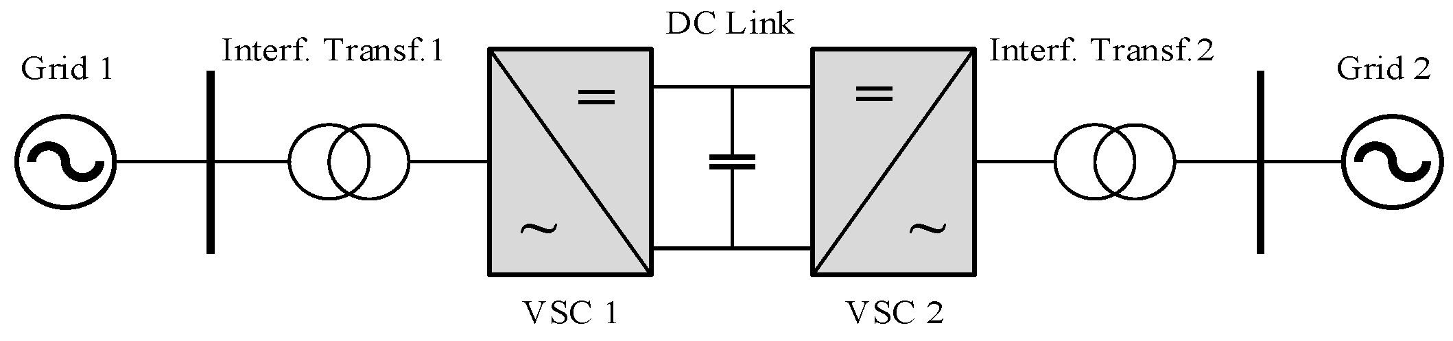
2.1. Back-to-Back MVDC System Topology

The back-to-back configuration is shown in Figure 1, consisting of two power conversion units connecting two AC networks via a DC link to develop an asynchronous AC-AC connection [10]. These power conversion units can be two-level, three-level, multilevel, or cascaded VSC-based power converters. The coupling transformers are used to interface each power conversion system, provide grounding for the system to suppress fault current, match grid voltages to the power converter AC voltages, and help smooth the fundamental current. However, some recent studies have proposed transformerless topologies, aiming to reduce the size and cost of the system.

2.2. Multi-Terminal MVDC System Topology

The multi-terminal configuration depicted in Figure 2 is an extended version of the back-to-back topology and enables the connection of more than two AC networks through a common DC link [21]. Although this topology can provide similar features to the conventional back-to-back systems and ensure improved security and reliability of supply, it requires more sophisticated control, higher cost, and larger size systems.

2.3. Unified Power Flow Control System Topology

The UPFC system displayed in Figure 3 comprises shunt and series-connected power conversion units linked via a common DC circuit [22]. The series-connected power converter controls the voltage magnitude and phase angle at its connection point, in that way the power flow is controlled between interconnected networks. On the other hand, the main role of the shunt power converter is to deliver the power required by the series converter through the DC link and provide independent control over the reactive power at its AC connection point.
The main benefit of the UPFC system is the high potential power flow that can be achieved by a relatively smaller rated power conversion system imposing voltage magnitude and phase angle differences. However, this feature is dependent on the network’s configurations, operation constraints, normal operating conditions, and the location of the UPFC system. Inherent drawbacks of the UPFC are the requirements for a complicated control scheme and protection system to undermine the disturbances and fault levels across the AC networks and that the UPFC system should be connected between power systems that are already synchronised.

3. Multilevel Power Converter Topologies

A PE-based device that can operate as either a power inverter (DC to AC) or a power rectifier (AC to DC) is called a power converter. The two-level power converter with the topology shown in Figure 4 has been the most commercially available and widely used for low voltage applications. The main evident difference between the two-level and multilevel power converters as their names imply is the output voltage; the two-level AC output phase voltage alternates between + V d c / 2 and V d c / 2 , while the multilevel output has more than two voltage levels, which results in more sinusoidal waveform and thus lower harmonic distortions.
For multilevel converters, the DC-link is split over more than one capacitor, unlike the two-level converter that consists of only a single DC capacitor. The use of multiple series DC capacitors enables the aggregation of multiple voltages with the power semiconductor devices for commutation and thus forming high voltage at its output, and simultaneously allows each switching device to withstand a reduced voltage level appearing across each DC capacitor, which determines the power semiconductor switches rating.
The advances in PE switching devices for handling high-power capabilities have made the power converters feasible for high-power applications. For high-voltage systems, it is problematic to directly connect a power semiconductor switching unit to a high voltage DC-link because the stray inductance and capacitance present within these switching devices can result in an undesirable voltage overshoot and device damage. Instead, a series connection of multiple switches with lower voltage ratings is beneficial to improve the conversion system reliability [23,24].
Generally, the benefits of utilising multilevel converters over the conventional two-level power converters can be summarised as:
  • The output voltage and current of a multilevel converter have reduced distortions in comparison to a two-level converter;
  • Because multilevel converters have several output voltages levels, the dv/dt stress is decreased, which in turn lessens the Electromagnetic Compatibility (EMC) problems;
  • The switches of multilevel converters can be operated using PWM of the fundamental frequency or higher switching frequencies. However, high switching frequency causes higher switching losses, which decrease the overall efficiency of the conversion system;
  • The multilevel converter makes better utilisation of the DC-link voltage when compared to the two-level converter.
Several research works have been dedicated to multilevel converters in terms of topologies, control, and operation with different proposed modulation schemes. Cascaded H-Bridge (CHB), Neutral Point-Clamped (NPC), and Flying Capacitor Clamped (FCC) converters have been appointed as the most promising multilevel topologies for future power systems. A brief overview of the three common multilevel converter topologies is presented next and the best candidate based on the literature survey will be nominated for the MVDC system applications in the power distribution networks.

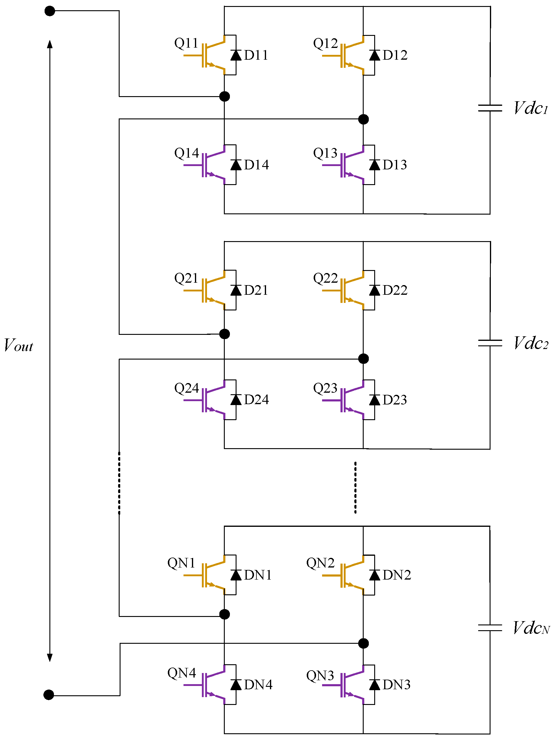
3.1. Cascaded H-Bridge (CHB) Multilevel Converter

The CHB multilevel converter was originally proposed in 1975 [25]. The concept of such a converter is to connect multiple DC-sourced full-bridge units in series to produce a staircase voltage waveform at the AC output. The single-phase structure of the CHB converter is demonstrated in Figure 5. The AC output of each H-bridge converter depending on the switches’ states can be + V dc , − V dc , and 0, and by establishing different conduction times between each unit, a staircase voltage waveform of (N + 1) levels at the AC output ( V out ) can be formed with a peak of (N × V dc ), where N is the number of H-bridge units used. This is made feasible by the series connection of multiple DC capacitors (or DC sources) to the overall AC output terminals with a suitable control scheme over the power switching devices of each unit.
Advantages:
The levels of the AC output voltage are more than the number of H-bridge units used;
With a high number of H-bridge units, an AC output with very low harmonic distortions can be achieved even with a lower switching frequency;
System modification simplicity due to the series H-bridges modularity.
Disadvantages:
The main constraint of the CHB converter is that independent DC capacitors (or sources) are essential for each H-bridge unit that consequently restricting its application;
Due to harmonic distortion reductions requirements, a high number of H-bridges is used for a high number of AC output levels, which means more DC capacitors and thus a bulky and costly system;
The complexity of the control system to operate the CHB converter for maintaining equal voltages across the DC capacitors when controlling output active and reactive power components.

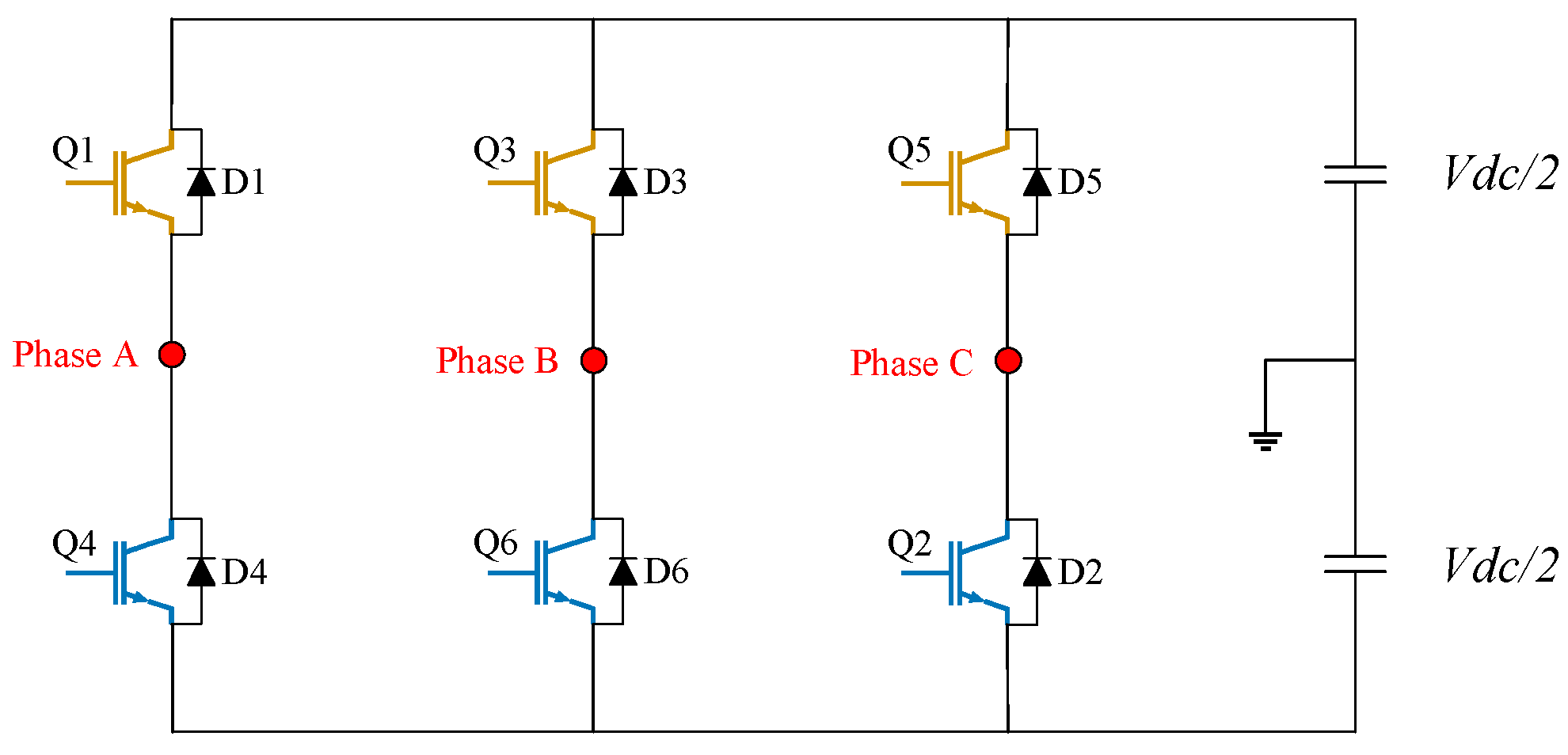
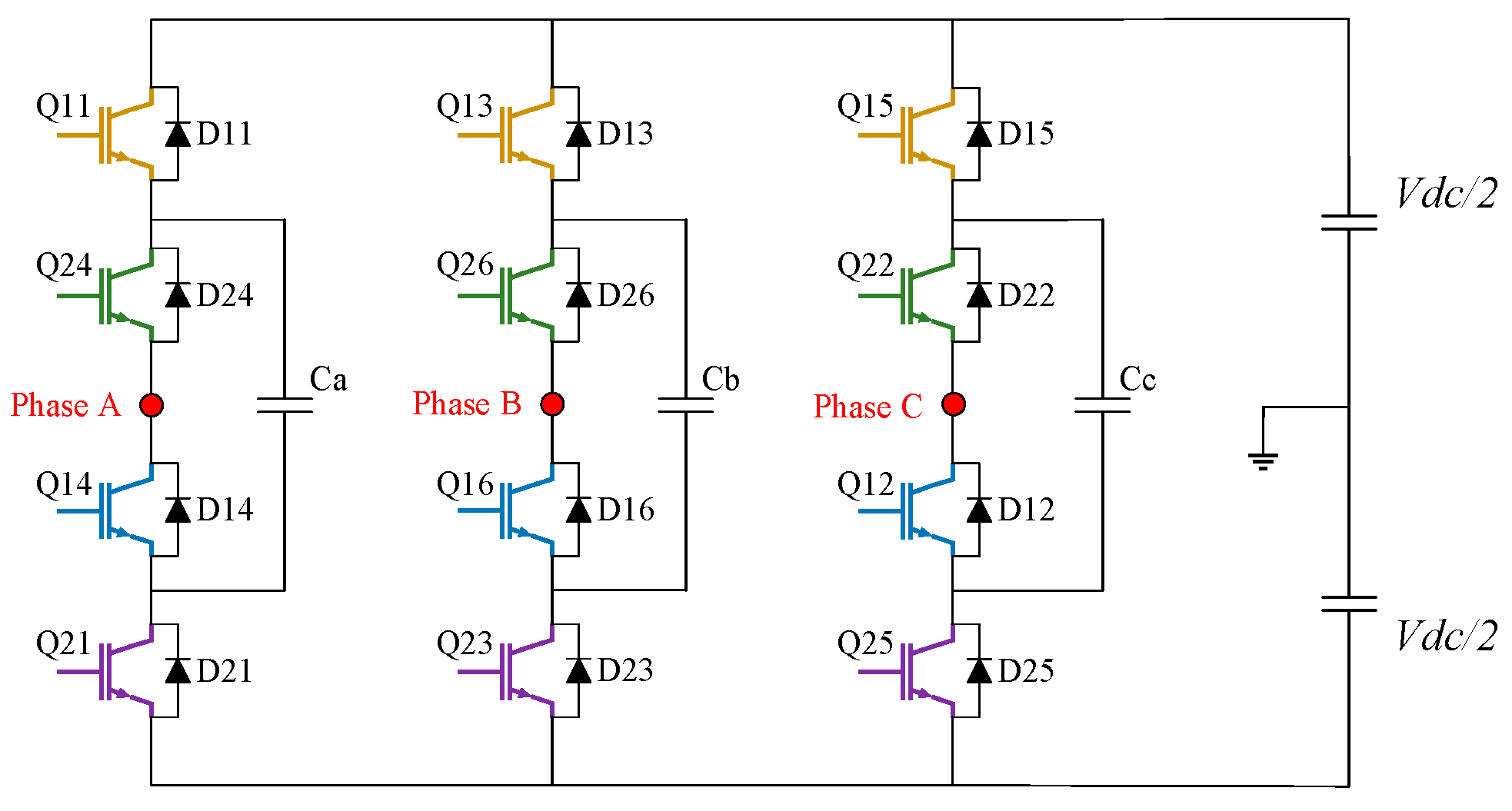
3.2. Neutral Point-Clamped (NPC) Multilevel Converter

The NPC or diode-clamped multilevel converter was first introduced in 1981 with diodes blocking the DC sources to establish a neutral point defining a third voltage level [26]. The three-phase topology of a three-level NPC converter is depicted in Figure 6. In this structure, the A, B, and C-phase share a common DC link, which comprises two capacitors connected in series. These capacitors divide the voltage of the DC link via the middle point into three levels ( + V dc / 2 , V dc / 2 and 0) that appear at each AC output phase voltage of the converter by a suitable control over the power switching devices. For a single leg, there are two complementary switching devices (Q11, Q14), which are the main switches, and (Q21, Q24), which are the auxiliary switches clamping the output terminal to the neutral point (N) through the two clamping diodes.
Advantages:
A common DC-link is shared by the three-phase terminals, minimising the number of DC capacitors required, and system size and cost;
Since the DC-link voltage is divided through the midpoint, lower voltage rating switches can be utilised, and voltage stress issues can be minimized;
Lower output harmonic distortions and high efficiency with a lower switching frequency;
The pre-charging of the DC capacitors as a group is possible, thus improving system dynamics.
Disadvantages:
Increase in the number of diodes required for clamping;
Voltages across the DC capacitors must be balanced for all operating conditions, thus requiring an effective control system.

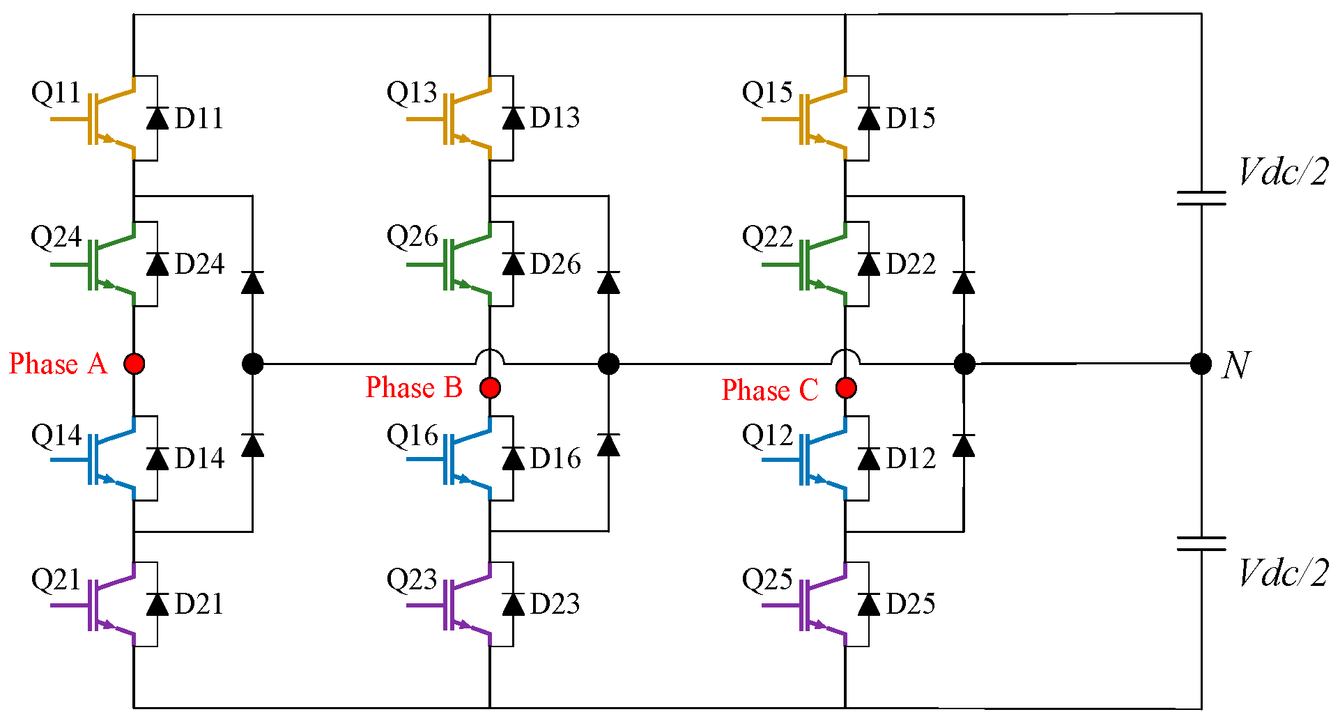
3.3. Flying Capacitor Clamped (FCC) Multilevel Converter

The FCC converter has a similar topology as that of the NPC converter but with clamping capacitors replacing the clamping diodes, proposed in the 1990s [27]. The role of clamping capacitors is to clamp the voltage of the switch to the voltage that appears across the DC link. Consequently, each AC output level in the staircase waveform reflects the voltage across each DC-link capacitor. The three-phase three-level FCC converter is displayed in Figure 7. Like the NPC converter, the FCC topology has a common DC link split by the two capacitors connected in series. Each AC output voltage with an appropriate switching of the power semiconductor components has three voltage levels: + V dc / 2 , V dc / 2 , and 0. The functionality of the clamping capacitor is to clamp the switching device to a reduced DC voltage appearing across a DC capacitor, which is the role of clamping diodes used in the NPC converters.
Advantages:
The voltage across capacitors can be balanced by the redundant switching states available;
Short duration outages ride through capability due to the increased number of capacitors.
Disadvantages:
The high cost and the bulky size of the system due to many capacitors in comparison to the NPC topology;
Requirement of a separate pre-charge circuit and complicated control system for voltage balancing of clamping and DC link capacitors.
The different multilevel converter topologies can also reduce the size and cost of the output filters and improve the power conversion efficiency. The three-level NPC and FCC converters, for instance, require half the output inductor for a given switching frequency used in two-level converters and thus reduce the output ripples. Additionally, the switching devices in the three-level converters have half the voltage rating of that used for two-level converters, and therefore reduces the voltage stress across the power converter components and switch losses and improves the system reliability [28].
Comparative studies of switch losses comprising switching and conduction losses and DC capacitor losses of most common topologies were conducted in [29,30]. They concluded that the conventional two-level converter results in significantly higher losses than the CHB and NPC converters even with lower switching frequencies due to the high-voltage rating of switching devices used. For the three-level topologies, switch losses are almost equal for the CHB and NPC converters, assuming equivalent modulation techniques. In terms of DC capacitor losses, the CHB and FCC converters have significantly more capacitor losses than conventional two-level and three-level NPC converters, which proved to be equal. However, increased switch losses of two-level converters cannot compensate for their lower DC capacitor losses, unlike the NPC converter, which proved to be the most efficient and promising topology for high-voltage and high-power applications. In conclusion, as it can be seen from the comparisons made in the literature and detailed discussion presented earlier, the NPC converter topology with the relatively minimised cost and size, lower associated switch and DC capacitor losses, and control design simplicity, stands out as the optimal choice for high-voltage and high-power applications, such as the MVDC systems.

4. Modelling and Control Development of an MVDC Converter

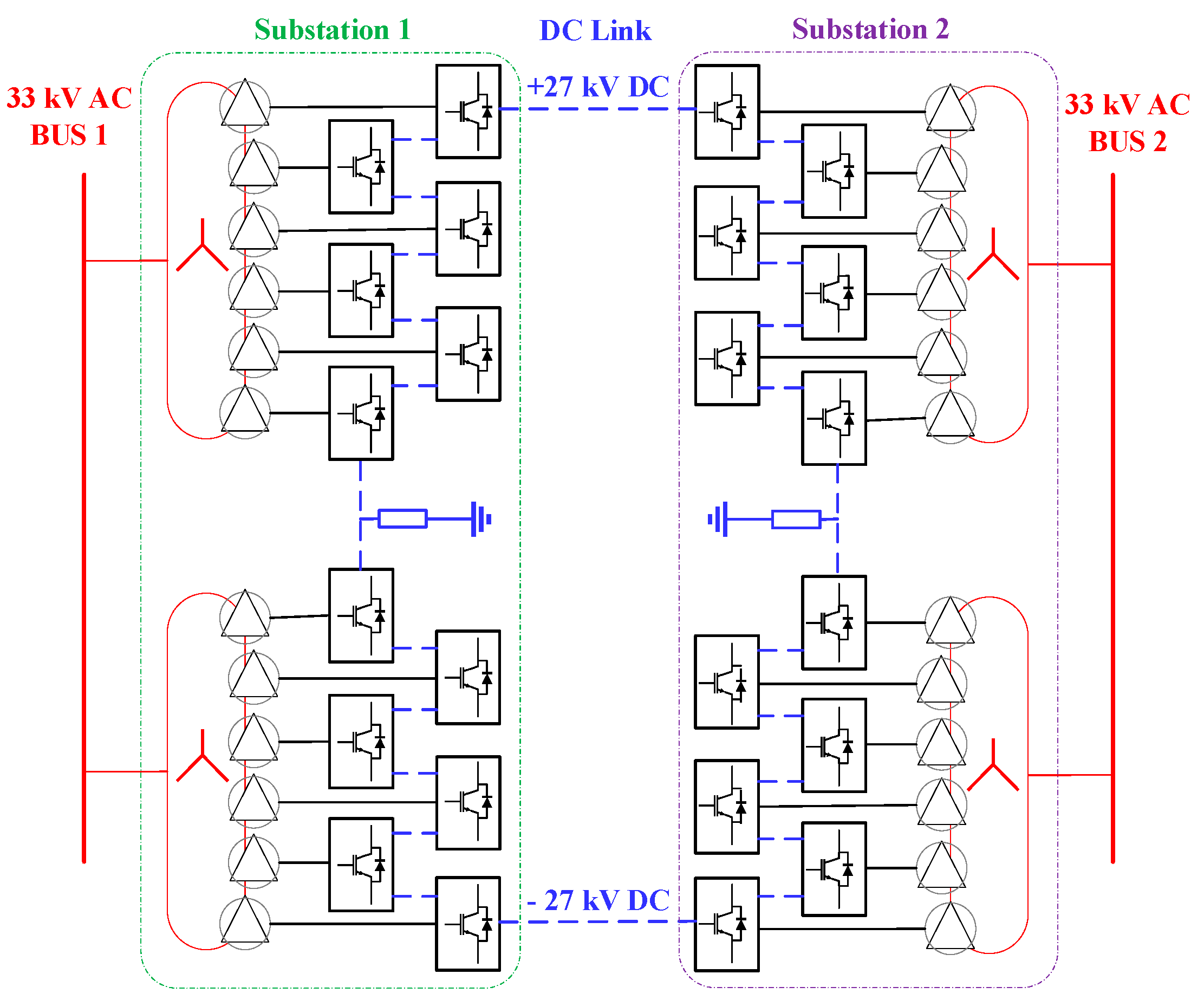
4.1. Topology and Specifications

The first step is to model the power converters with a full representation of the power switching devices in order to evaluate the harmonic performance of the developed MVDC converter. Figure 8 depicts the developed MVDC system with parameters listed in Table 1. The MVDC converter is comprised of a number of three-phase three-level NPC voltage source converters that are coupled in a unique structure to construct a return-grounded bipolar configuration. Each of the six power converters is linked to the AC network at each substation through a 17 MVA three-phase transformer with high-voltage star-connected windings and six 2.1 kV delta-connected windings. The overall topology is established by two transformers connecting the twelve power conversion units, while the total DC link of 54 kV is formed by the series connection of each converter DC link of 4.5 kV. A grounding resistor connects the mid-point of each substation to the ground, and a DC reactor is employed to filter out DC ripples.

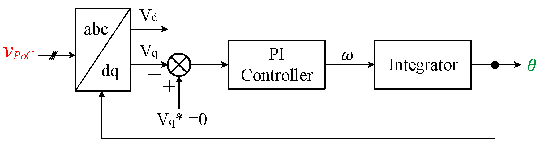
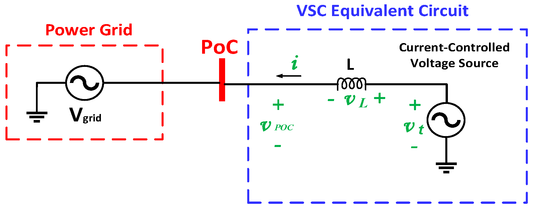
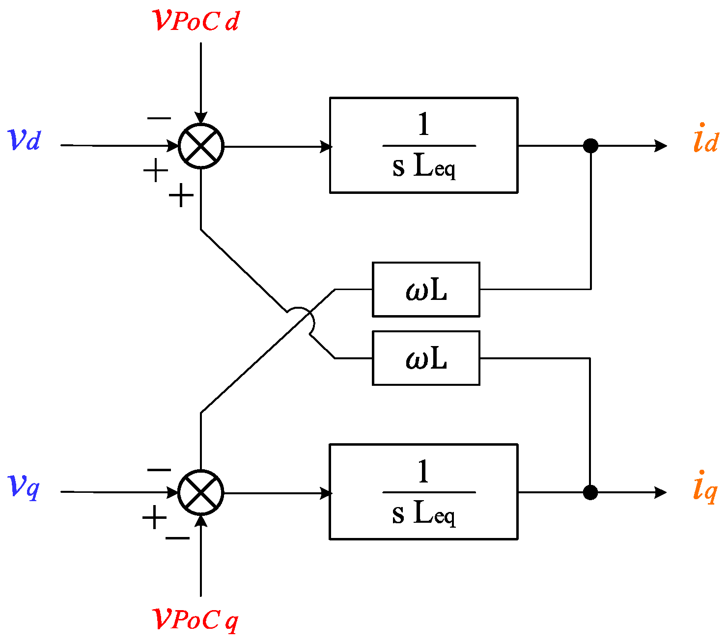
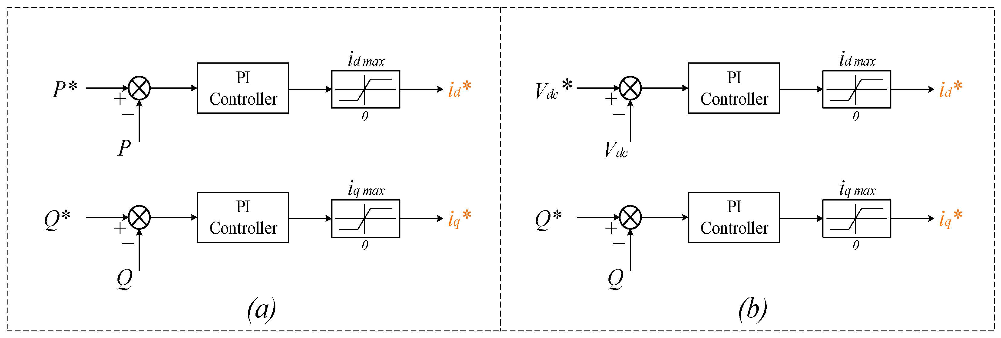
4.2. MVDC Converter Control System
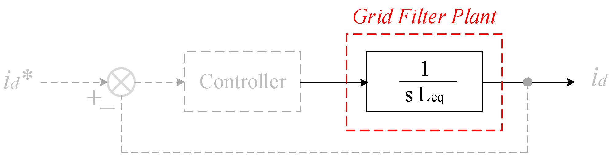
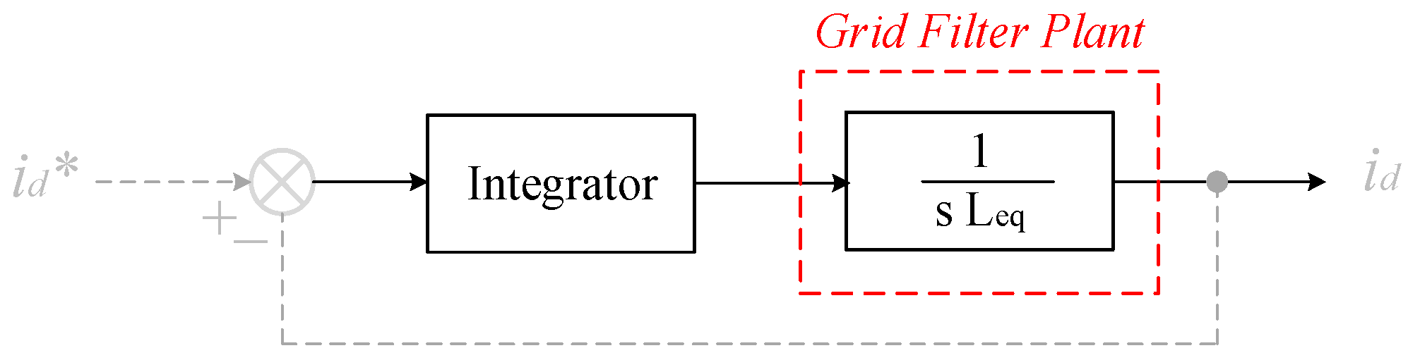
The MVDC model employs the power flow control method, which is commonly used to operate a VSC-based typical back-to-back power conversion system. It can manage the active power flow between the AC networks, control the reactive power at each AC end independently under normal operating conditions, and isolate a faulty circuit. The MVDC converter is operated using dual closed loops in the synchronously rotating reference frame in this control mode. The decoupling between the active and reactive power components, as well as the intrinsic suppression characteristic of fault currents, are the two main benefits offered by this control system [10].
The synchronisation of a grid-connected power converter with the grid voltage at the Point of Connection (PoC) is achieved by a PLL [31,32]. Figure 9 shows a PLL control method based on Park’s transformation theory, in which the q-component of the grid voltage is regulated to zero, a PI controller is used to estimate the associated angular frequency (ω), and an integrator is employed to determine the phase angle (θ). The PLL established in Simscape/Simulink, with a comparable architecture and automated gain control employed in this work.
  • Inner Control Loop
The three-phase three-level NPC converter may be represented as a voltage source behind an impedance reflecting its equivalent inductance provided by the power transformer as illustrated in Figure 10. This representation can help effectively construct the inner current control loop [33].
The following equation in the abc-frame is found by applying Kirchhoff’s voltage law.
v L = L di dt = v t v POC
When Park’s transformation is applied with the cross-coupling caused by inductance behaviour, the following results are obtained:
v L d = L d i d d t = + L ω   i q + v t d v POC d
v L q = L d i q d t = L ω   i d + v t q v POC q
By applying the Laplace transform to the time domain equations, the following results are obtained:
I d   Ls = + L ω   I q + V t d V POC d
I q   L s = L ω   I d + V t q V POC q
The grid filter model for a reduced-order model of the power converter may be derived using the Laplace equation, as shown in Figure 11.
Figure 12 shows the control circuit for controlling the output current of the VSC converter modelled in the dq-frame. The grid voltage and cross-coupling components in the control circuit have the opposite signs from those indicated in the complete grid filter plant. This is done to compensate for and cancel out their influence on the system under the control.
The inner control circuit receives dq-current signals from the outer control loop and supplies the PWM circuit with the appropriate reference signals. A PI controller processes the difference between the reference and measured dq-current components, and the reference signals (vref) are derived following the inverse Park’s transformation. To enhance the transients of the conversion system, compensations of the feedforward voltage and cross-coupling current due to the dq transformation are typically used [33,34]. The train pulses for switching devices like Insulated Gate Bipolar Transistors are then generated by the PWM circuit.
  • Outer Control Loop
The outer control loop illustrated in Figure 13 is simple to implement. It is utilised to give the reference dq-current components for the inner loop depicted in Figure 12 using PI controllers. The inner loop control structure is the same for all power converters in each substation; however, the outer loop control structure varies depending on where the converter is located. Converters at Substation 1 are controlled using the P-Q control scheme, whereas those at Substation 2 are controlled using the Vdc-Q control method.
The P-Q regulates active and reactive power to specified set points, whereas the Vdc-Q keeps the DC link constant for a steady active power flow and controls reactive power at the AC end, as the names indicate. Dynamic current limiters are often used to detect and protect systems from overcurrent under abnormal operating situations [10,33].

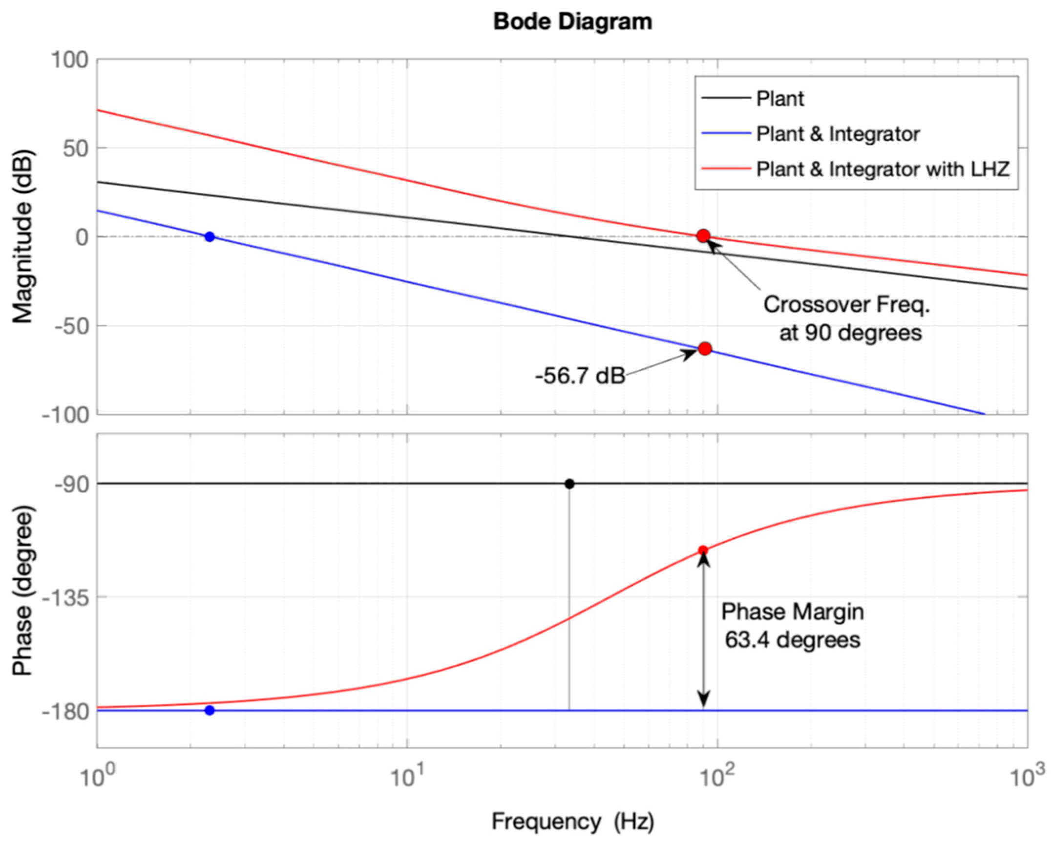
5. PI Controller Parameters Design

The design of the PI controller’s parameters could be accomplished by using a variety of techniques. Robust control design approaches, such as high-order control systems, are difficult to implement in practical power conversion systems [33]. Nonetheless, the simple loop-shaping method provides effective and satisfactory control performance [34], so it is used to tune the PI controller’s parameters for the MVDC converter inner current loop, whereas the outer loop PI controllers are tuned using a trial-and-error approach to achieve the desired performance. Because voltage disturbances and cross-coupling components are significantly important during transients, they can be neglected when the power network is considered to be balanced and steady-state performance is a concern.
Furthermore, because its response time is substantially slower than the inner current loop, the DC link voltage can be considered to remain constant without disturbances [33]. Moreover, when the system operates at a unity power factor, the d- and q-component models are comparable in terms of representing the overall system response, allowing the converter model to be reduced further, as illustrated in Figure 14.
The method begins with an open-loop Bode plot of the plant model of the system under control, followed by the placement of an integrator with a Left-Hand Zero (LHZ) to obtain the requisite open-loop phase margin. Finally, a factor is used to adjust the crossover frequency in order to match the performance requirements. The PI controller design goal is to adjust the bandwidth of the current control to be between 1/20 and 1/10 times the switching frequency ( f sw ), while ensuring sufficient close-loop stability by regulating the phase margin typically higher than 45 degrees with a slope of −20 dB/dec [33,34].
The transformer leakage reactance for each winding linking each power conversion unit is presumed symmetric for the MVDC system, and it is used in the grid filter plant for control design. The low voltage equivalent inductance (Leq) is roughly 2.15 mH at 2.1 kV and 2.9 MVA. Figure 15, Figure 16, Figure 17 and Figure 18 depict the loop-shaping approach, while Figure 19 depicts the open-loop Bode plots of each stage of the present control system.
To begin, instead of using a PI controller, an integrator ( k g / s ) is used to regulate the system plant. The system in Figure 16 is unstable with a continuous zero phase margin, regardless of the controller gain ( k g ), which can only adjust the crossover frequency, according to the Bode plot. As a result, the phase margin cannot be changed using the simple integral controller, and an LHZ must be incorporated, as indicated in Figure 17.
System stability can be accomplished by modifying the system phase margin with a low-frequency LHZ in the controller transfer function. When the switching frequency is low, the inner control loop’s crossover frequency is set to 90 Hz (i.e., f sw / 10   ), and the LHZ frequency ( f z ) is set to 45 degrees, which is much below the anticipated crossover frequency.
The system now has a phase margin of 63.4 degrees, which ensures system stability, but the crossover frequency has to be modified according to the Bode plot. The integral controller gain ( K g ), which solely affects the amplitude of the control loop, is now used to change the crossover frequency to 90 Hz. The gain calculation is based on the system requirement to reach the 0 dB at 90 degrees. Consequently, the gain for the 56.7 dB is calculated as 10 56.7 / 20 , as seen from the Bode plot figure. The controller’s final model is as follows:
Integrator   &   LHZ = K g s     (   s ω z + 1   ) = K g s   ( s 2   π   f z + 1 )
Because of its ease of implementation and modelling, the typical PI controller depicted in Figure 18 is employed. It may also be conveniently implemented in a simulation tool like Simulink/MATLAB in a discrete version. The proportional gain ( K p   = 1.132) and integral gain ( K i   = 320) are easily determined using the loop-shaping approach controller model as follows:
PI   controller = K g s   ( s 2   π   f z + 1 ) = K g 2   π   f z + K g s = K p + K i s

6. Pulse Width Modulation Techniques

In comparison to the space vector modulation technique, the SPWM approach, which is based on a reference modulation signal compared to a high-frequency carrier signal, has better performance under normal and abnormal operating conditions. It also has better performance with different power flow profiles and less complex control for balancing the DC capacitor voltage [35]. The regulated sinusoidal reference signal of the power frequency is compared with two triangular carrier signals to determine the switching frequency at which the switching devices operate. The technique for the three-level NPC converter configuration is shown in Figure 20 for a single leg. To create switching pulses for the three-phase converters, a 120-degree phase shift between the three reference modulation signals must be established while maintaining the same high carrier frequency [23].
The converter output voltage frequency is determined by the reference sinusoidal signal frequency, while the switching frequency is determined by the carrier signal frequency, which should be carefully selected for a given power frequency to prevent asymmetry between the output voltage positive and negative half-cycles, as shown in Figure 21. The frequency–modulation index (mf) which is the ratio of the switching frequency to the power frequency must be an odd integer and divisible by three [36]. The resulting voltage spectra of several representative pulse numbers are shown in Figure 22. The zero-sequence harmonic orders are missing when the pulse number is a multiple of an odd integer and divisible by three, as in the instance of mf = 39.
When the pulse number is only an integer but not divisible by three (i.e., mf = 37), however, the triplen harmonics (33rd, 39th, 45th, 69th, etc.) appear, resulting in an asymmetrical output voltage waveform between the half cycles, which affects the operation of power system components, such as heating of electric motors, transformers, and neutral conductors [37]. Consequently, the lower switching frequency of 900 Hz is chosen for the MVDC converters at the power frequency of 60 Hz, resulting in 15 pulses, which is an odd integer and divisible by three.

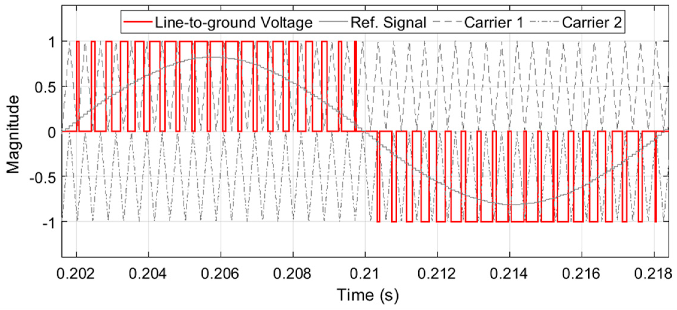
6.1. Interleaved SPWM Technique

The most commercially available grid-connected converters are usually designed with an LCL passive filter [31,33]. For high-power applications, a lower switching frequency is employed to reduce switch losses and therefore disproportionately larger passive filter components are required for harmonic currents reduction. Besides the evident burden of the filter size and cost, large filter components have further disadvantages on the power system. Firstly, utilising a large inductor influences the system dynamic response that can be critical for fault ride-through capability with the presence of grid disturbances, such as voltage dips and swells. A large capacitance implies high currents drawn from the network, and this requires a more complicated control system to compensate for the power factor at the converter output [38]. The large capacitor additionally provides a low impedance path for harmonic currents developed from the grid background voltage harmonics that eventually raise the converter output THD. Moreover, the grid-side inductors, adding extra cost and size, are occasionally used in two-level converters to prevent the injection of high-frequency current components into the power grid. This additional inductor is undesirable when the converter is connected to a grid or operated autonomously and supplying a nonlinear load as it significantly increases the voltage distortions at the connection point. This is because of the harmonic impedance of the inductance that increases linearly with the frequency.
The interleaved topology first received attention in a wide range of DC/DC power conversion applications, such as electric and hybrid electric vehicles, communication power suppliers, and solar Photovoltaics systems. The main reason for adopting this topology is to improve the system’s power density, dynamic performance, and efficiency. The interleaved topology has also been applied to power inverters [39] and rectifiers [40]. Interleaved configurations are formed by connecting an N power converter in parallel and imposing an equal phase shift between their switching instants over the switching period. There are several benefits of the interleaved configuration over the conventional topology for grid-connected systems. By establishing the phase shift between the switching pulses of the parallel converters, the overall current distortions are N times lower, and its apparent switching frequency is N times larger than that of a single power converter. Therefore, the switch losses of each power converter can be significantly reduced since a lower switching frequency is used and the need for the large LCL passive filter to reduce the output harmonic currents is compromised by a smaller filtering inductance, which is usually provided by the interfacing power transformer leakage inductance. The decrease in switch losses reduces the cooling system size and improves the overall efficiency [31].

6.2. Interleaved SPWM Application in the MVDC Converter

Multiple three-phase three-level VSC-based NPC converters are connected in a cascaded arrangement for the MVDC converter detailed model presented in this work. Because the MVDC converter has a low switching frequency to prevent switch loss, an equally interleaved SPWM technique is developed for the converters in each substation to limit distorted currents in the high-voltage winding and their influence on each power transformer. The lower switching frequency reduces switching losses, which is beneficial in high-power applications. The interleaved SPWM technique for six MVDC converters is depicted in Figure 23, with just the upper carriers displayed for demonstration purposes. The detailed mathematical models of the interleaved SPWM introduced for the MVDC converter model developed in this paper are provided in [39], which are not included here for the sake of article length.

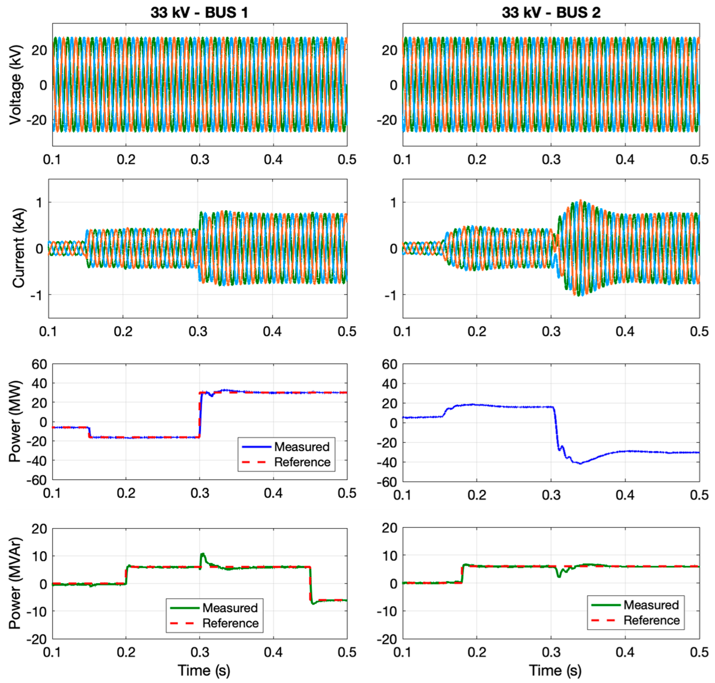
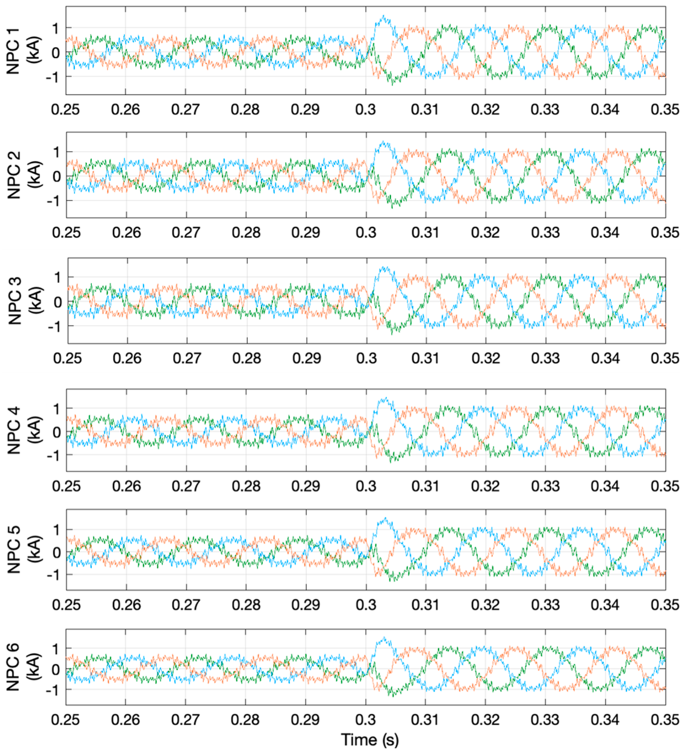
7. MVDC System Performance Analysis

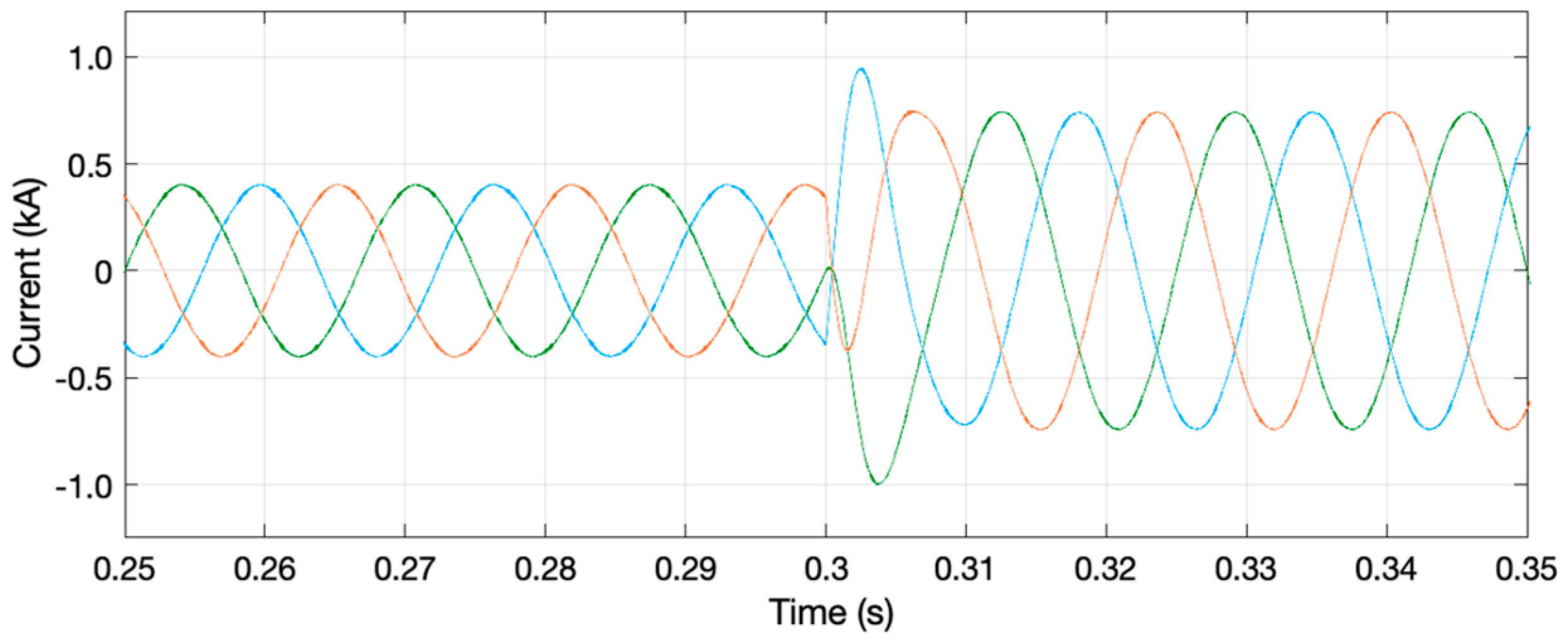
7.1. The Fundamental Frequency Performance of the MVDC Converter

The performance of the MVDC system is investigated under a variety of operating scenarios, with infinite AC power supplies at both ends. The characteristics of the MVDC system are used to represent this system in the Simulink/MATLAB simulation environment. For analysing both transients and steady-state performance of the system, a thorough model containing the switching behaviour of the switch devices is used. This model also examines the performance of the control scheme for power flow regulation, assuming Substation 1 is run in P-Q control mode and Substation 2 is controlled in Vdc-Q control mode. At both 33 kV buses, Figure 24 depicts the system voltage and current traces, as well as the instantaneous active and reactive power.
The active power reference was configured to supply 15 MW (1.25 MW per converter) to BUS 2 in 0.15 s and 30 MW (2.5 MW per converter) to BUS 1 in 0.3 s through the MVDC system. Each AC side’s reactive power, on the other hand, is adjusted separately. Between 0.2 and 0.45 s, Substation 1 provides 12 MVAr (1 MVAr per converter) and then absorbs the same amount of reactive power. After 0.18 s, Substation 2 delivers 12 MVAr (1 MVAr per converter), with a DC link voltage of 4.5 kV per converter and 54 kV over the total DC circuit.
Without substantial overshoots during transients, the control system precisely and swiftly follows the reference set points at steady-state. The results indicate that under normal conditions, the MVDC system offers immediate and retentive power flow with flexible control over the active and reactive power flow. The high step transition in the active power reference (at 0.3 s), which is not practical in a real power system, causes a notable variance in the reactive power measurement at both AC ends. This is due to the DC power transfer and DC capacitors being affected by the intrinsic coupling effect between active and reactive power in power systems.
Figure 25 shows the DC voltage of the MVDC system. It remained constant during the steady-state period, with minor transient fluctuations due to step changes in the reference active power, which generates an immediate power imbalance through the DC link. The DC voltage fluctuation induced by a 15 MW step change at 0.15 s is substantially lower than the DC voltage variation caused by a 30 MW step change at 0.3 s. These undesired fluctuations could be reduced by using larger DC capacitors. However, instead of increasing the DC link capacitors, the variations can be addressed by slowing down the DC voltage control loop response or they can be decreased when the active power step changes are reduced or progressively modified, as is the case in real power system operations.

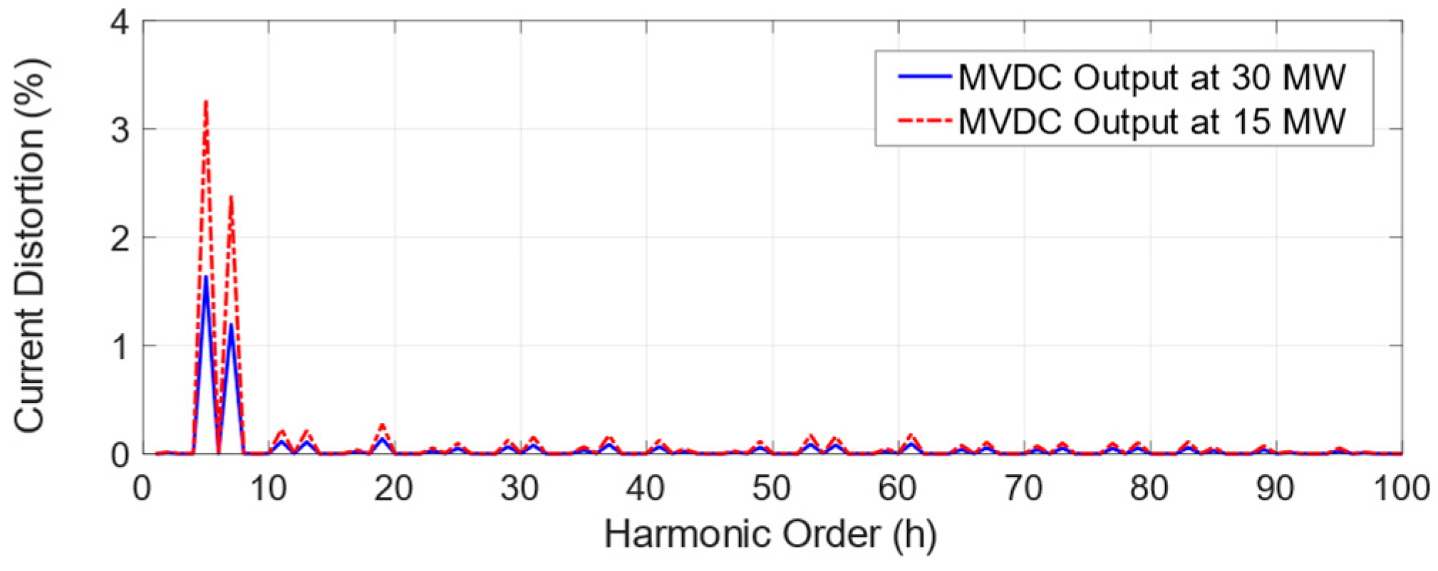
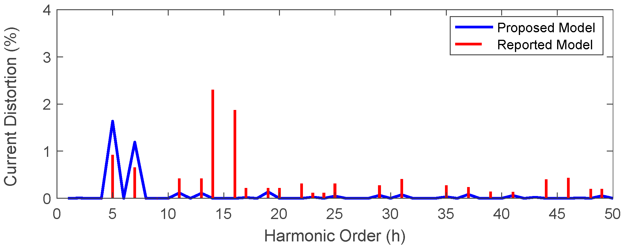
7.2. The Harmonic Performance of the MVDC Converter

The detailed model of the MVDC converter, including the switching behaviour of switching devices helps accurately investigate the harmonic performance of such a system. To eliminate the impact of the DC voltage control system and the variations due to the large power being exchanged, a constant DC voltage source was used for maintaining the total DC link voltage at the rated setpoint of 54 kV. The output AC voltage of each NPC-VSC system at Substation 1 is depicted in Figure 26, only six power converters’ output voltage traces are shown for illustration. The converter voltages are applied directly to the secondary windings. The converters produce voltage pulses that are phase-shifted by 1/6 of the switching period. Thus, the transformer secondary currents will contain the PWM switching ripple, which circulates mostly between transformer secondary windings. Due to the phase shift in the secondary current, the current at the primary terminals will have relatively low distortions because of the switching ripple/cross current cancellation. The LV winding current waveforms for two different active power setpoints are illustrated in Figure 27. The three-phase NPC converters operate at a unity power factor and inject a total of 15 MW till 0.3 s and then supply a 30 MW afterwards to the 33 kV power grid. From the winding current waveforms, it can be observed that the current ripples in different windings could be different due to interleaved SPWM method excluding the asymmetry of the coupling/impedances between LV windings.
The FFT solution is adopted for computing the equivalent LV current harmonic content. The spectra for the two different operating conditions are superimposed in Figure 28. It can be noticed that the major distortions in the LV winding currents occur in the first switching frequency band around 900 Hz (15th harmonic order), which is attributed to the low pulse number of the PWM. The regular sampled PWM has resulted in negligible non-characteristic harmonic components. The LV winding current THD is about 30% and 17% for the half and full rated operating power of the MVDC system, respectively.
The MVDC converter output current comprises fundamental and harmonic components resulting from the switching behaviour of the cascaded NPC-VSC power converters. The trace of the total output current is shown in Figure 29, and the current spectra for the two different operating conditions are depicted in Figure 30. It can be observed that the output current is dominated only by low-order harmonic components. However, the switching frequency harmonics have been significantly compensated by the mutual cancellation of the cross-currents flowing in LV windings (due to the interleaved SPWM). The development of the interleaved SPWM scheme has consequently reduced the harmonic components of high orders of the total output current.
The FFT solution is used to analyse the harmonic contents of the output waveforms of the MVDC converter. At full-load operation, roughly 17% THD is encountered at low-voltage windings current and about 2% THD is experienced at high-voltage windings current. Despite the fact that the MVDC system is rated at 30 MW, the transmitted power might fluctuate due to changing power demand. As a result, the MVDC converter operating points have an impact on its harmonic performance. When a 15 MW is transferred between the AC grids, for example, 4% THD can result. Among the low-order harmonic components, the 5th and 7th harmonic orders dominate the total output current. When PFC capacitor banks achieving a lower-frequency resonance are in operation, these low-order harmonics can be amplified and trigger significant challenges to the power operator. However, even at reduced magnitudes, high-order harmonics can interact with power system impedance, resulting in high-order voltage distortions. As a result, a wide harmonic performance study of the MVDC system’s harmonics in a power network must be conducted to investigate their severity in real power systems.
To validate the proposed MVDC converter model and highlight the effect of the interleaved SPWM technique proposed, the harmonic emission of the MVDC converter modelled in this paper is compared with that of the detailed MVDC converter model developed in [19]. Figure 31 shows the output current spectra of the developed and established MVDC converter models. It can be observed that the output current of the MVDC converter model with the interleaved SPWM has a maximum THD of 2%, in comparison with the established model that has up to 4% THD at rated power. For the established model, the switching frequency sideband harmonic components (i.e., 15th, 30th, 45th) are dominant, while the developed model with the effect of the interleaved SPWM has a significantly eliminated the even-order harmonic components, which can adversely affect the operation of power transformers and motors operation [37].

8. Conclusions

The introduction of the MVDC converters to the power distribution networks will help increase the networks’ hosting capacity for more DER-based power sources and meet future growing energy consumption without triggering stability and thermal issues. An overview of the different configurations of the MVDC systems and a comparative analysis of the multilevel power converter topologies for such applications were presented. Furthermore, the detailed model of an MVDC converter with a suitable control system was developed to accurately capture the harmonic performance of such an application, which will further enable harmonic propagations analysis studies in the distribution network. An interleaved SPWM scheme was proposed to improve the MVDC converter harmonic performance and validated using the Simulink/MATLAB simulation environment. The tuning of the PI controller’s parameters was addressed using the loop-shaping technique. The MVDC system performance at the fundamental and harmonic frequencies for different operating conditions was analysed, and the effectiveness of the control system and the harmonic reduction method were discussed. It was observed that the output current of the MVDC converter model developed with the interleaved SPWM has a maximum THD of 2% in comparison with the established model, and the interleaved SPWM has a significantly eliminated the even-order harmonic components, which can affect the operation of power transformers and motors. Apart from this work, an extensive analysis study is required for addressing the limitations associated with the MVDC converter topology in terms of circulating currents, DC voltage balancing, and fault isolation. The stability and sensitivity analysis of the proposed control system of the MVDC converter with respect to the inevitable delay due to the digital control implementation and signal processing should also be investigated with the consideration of abnormalities at the power network level. Moreover, harmonic instability studies have recently received considerable attention and, thus, the development of the harmonic state–space model of the MVDC converter is required. Comprehensive investigations of the impact of advanced control systems, such as adaptive and model predictive control systems, on the harmonic performance of such new MVDC technologies are required. The use of advanced controllers, such as Proportional Resonance for the low-order harmonic compensations should also be investigated for such an application. Furthermore, because power distribution networks are susceptible to operational abnormalities, such as voltage imbalance and fault occurrences, more research into the control performance for power harmonics improvements during these situations is required. It is also necessary to consider the impact of active control systems that compensate for fluctuations in power loads and other power sources on harmonic performance.

Author Contributions

Conceptualization, methodology, results analysis, discussion, and writing—original draft preparation, T.A.H.A.; F.A. and M.P., supervision, and writing—review and editing. All authors have read and agreed to the published version of the manuscript.

Funding

The Open Access (OA) charges of this work have been funded by the Cardiff University Institutional OA Fund, Reference number: 2022-OA-0407.

Acknowledgments

The corresponding author would like to thank Albaha University, Saudi Arabia, for sponsoring his postgraduate study at Cardiff University, UK. The authors would also like to thank the School of Engineering, Cardiff University, for supporting this research work by funding the APC for publishing this paper.

Conflicts of Interest

The authors declare no conflict of interest.

Nomenclature

ACAlternating Current
CHBCascaded H-Bridge
DCDirect Current
DERDistributed Energy Resources
DGDistributed Generation
dqDirect-Quadrature
EMCElectromagnetic Compatibility
FCCFlying Capacitor-Clamped
FFTFast Fourier Transform
LHZLeft-Hand Zero
MVDCMedium Voltage Direct Current
NPCNeutral Point-Clamped
p.u.per unit
PEPower Electronics
PIProportional Integral
PLLPhase-Locked Loop
PoCPoint of Connection
SPWMSinusoidal Pulse-Width Modulation
STATCOMStatic Synchronous Compensator
THDTotal Harmonic Distortions
VSCVoltage Source Converter
v L Transformer Inductance Voltage
v t Power Converter Terminal Voltage
v POC PoC Voltage
k g Integral Controller Gain
f z LHZ Frequency
K p PI Proportional Gain
K i PI Integral Gain
mfFrequency Modulation Index

References

  1. Rezkallah, M.; Chandra, A.; Hamadi, A.; Ibrahim, H.; Ghandour, M. Power quality in smart grids. In Pathways to a Smarter Power System; Elsevier: London, UK, 2019. [Google Scholar]
  2. Bloemink, J.M.; Green, T.C. Benefits of Distribution-Level Power Electronics for Supporting Distributed Generation Growth. IEEE Trans. Power Deliv. 2013, 28, 911–919. [Google Scholar] [CrossRef] [Green Version]
  3. Networks, S.E. 2015 ANGLE-DC Electricity Network Innovation Competition; Ofgem: London, UK, 2015; pp. 1–101. [Google Scholar]
  4. Alghamdi, T.A.H.; Anayi, F.J. Modelling and control development of an MVDC converter implemented for Albaha power network. In Proceedings of the 5th International Conference on Power and Energy Engineering (ICPEE), Xiamen, China, 2–4 December 2021. [Google Scholar]
  5. Alghamdi, T.A.H.; Anayi, F.; Packianather, M. Optimal Design of Passive Power Filters Using the MRFO Algorithm and a Practical Harmonic Analysis Approach including Uncertainties in Distribution Networks. Energies 2022, 15, 2566. [Google Scholar] [CrossRef]
  6. Tang, C.-Y.; Chen, Y.-F.; Chen, Y.-M.; Chang, Y.-R. DC-Link Voltage Control Strategy for Three-Phase Back-to-Back Active Power Conditioners. IEEE Trans. Ind. Electron. 2015, 62, 6306–6316. [Google Scholar] [CrossRef]
  7. Romero-Ramos, E.; Gómez-Expósito, A.; Marano-Marcolini, A.; Maza-Ortega, J.; Martinez-Ramos, J. Assessing the loadability of active distribution networks in the presence of DC controllable links. IET Gener. Transm. Distrib. 2011, 5, 1105–1113. [Google Scholar] [CrossRef]
  8. Maza-Ortega, J.; Barragán-Villarejo, M.; Romero-Ramos, E.; Marano-Marcolini, A.; Gómez-Expósito, A. Voltage source converter-based topologies to further integrate renewable energy sources in distribution systems. IET Renew. Power Gener. 2012, 6, 435–445. [Google Scholar] [CrossRef]
  9. Bloemink, J.M.; Green, T.C. Increasing distributed generation penetration using soft normally-open points. In Proceedings of the IEEE PES General Meeting, Providence, RI, USA, 25–29 July 2010; pp. 1–8. [Google Scholar]
  10. Cao, W.; Wu, J.; Jenkins, N.; Wang, C.; Green, T. Operating principle of Soft Open Points for electrical distribution network operation. Appl. Energy 2016, 164, 245–257. [Google Scholar] [CrossRef] [Green Version]
  11. Song, J.; Zhang, Y.; Gao, Z.; Cao, C.; Wang, Z.; Xu, F. Research on Topology and Control Technology of Soft Multi-State Open Point with Fault Isolation Capability. In Proceedings of the 2018 China International Conference on Electricity Distribution (CICED), Tianjin, China, 17–19 September 2018; IEEE: Piscataway, NJ, USA, 2018; pp. 1467–1473. [Google Scholar]
  12. Aithal, A.; Wu, J. Operation and performance of a medium-voltage DC link. CIRED Open Access Proc. J. 2017, 2017, 1355–1358. [Google Scholar] [CrossRef] [Green Version]
  13. Chen, J.; Ming, W.; Ugalde-Loo, C.E.; Wang, S.; Jenkins, N. Analysis and Mitigation of DC Voltage Imbalance for Medi-um-Voltage Cascaded Three-Level Neutral-Point-Clamped Converters. IEEE Trans. Power Electron. 2022, 37, 4320–4336. [Google Scholar] [CrossRef]
  14. Graaff, R.A.A.; Myrzik, J.M.; Kling, W.L.; Enslin, J.H.R. Series Controllers in Distribution Systems—Facilitating Increased Loading and Higher DG Penetration. In Proceedings of the 2006 IEEE PES Power Systems Conference and Exposition, Atlanta, GA, USA, 29 October–1 November 2006; IEEE: Piscataway, NJ, USA, 2006; pp. 1926–1930. [Google Scholar]
  15. Thomas, L.J.; Burchill, A.; Rogers, D.J.; Guest, M.; Jenkins, N. Assessing Distribution Network Hosting Capacity with the Addition of Soft Open Points. In Proceedings of the 5th IET International Conference on Renewable Power Generation (RPG) 2016, London, UK, 21–23 September 2016; Institution of Engineering and Technology: London, UK, 2016; pp. 1–6. [Google Scholar]
  16. de Graaff, R.A.A.; Myrzik, J.M.A.; Kling, W.L.; Enslin, J.H.R. Intelligent Nodes in Distribution Systems—Optimizing Steady State Settings. In Proceedings of the 2007 IEEE Lausanne Power Tech, Lausanne, Switzerland, 1–5 July 2007; IEEE: Piscataway, NJ, USA, 2007; pp. 391–395. [Google Scholar]
  17. Li, P.; Song, G.; Ji, H.; Zhao, J.; Wang, C.; Wu, J. A Supply Restoration Method of Distribution System Based on Soft Open Point. In Proceedings of the 2016 IEEE Innovative Smart Grid Technologies—Asia (ISGT-Asia), Melbourne, VIC, Australia, 28 November–1 December 2016; IEEE: Piscataway, NJ, USA, 2016; pp. 535–539. [Google Scholar]
  18. Joseph, T.; Liang, J.; Li, G.; Moon, A.; Smith, K.; Yu, J. Dynamic control of MVDC link embedded in distribution network-Case study on ANGLE-DC. In Proceedings of the 2017 IEEE Conference on Energy Internet and Energy System Integration (EI2), Beijing, China, 26–28 November 2017; IEEE: Piscataway, NJ, USA, 2017; pp. 1–6. [Google Scholar]
  19. Joseph, T.; Balasubramaniam, S.; Li, G.; Liang, J.; Ming, W.; Moon, A.; Smith, K.; Yu, J. Dynamic Average Converter Model for MVDC Link Harmonic Analysis. In Proceedings of the 2019 IEEE Milan PowerTech, Milan, Italy, 23–27 June 2019; IEEE: Piscataway, NJ, USA, 2019; pp. 1–6. [Google Scholar]
  20. Joseph, T.; Wenlong, M.; Gen, L.; Jun, L.; Moon, A.; Smith, K.; Yu, J. Analysis of Harmonic Transfer through an MVDC Link. In Proceedings of the 15th IET International Conference on AC and DC Power Transmission (ACDC 2019), Coventry, UK, 5–7 February 2019; Institution of Engineering and Technology: London, UK, 2019; pp. 1–6. [Google Scholar]
  21. Abdelrahman, M.A.; Long, C.; Wu, J.; Jenkins, N. Optimal Operation of Multi-Terminal Soft Open Point to Increase Hosting Capacity of Distributed Generation in Medium Voltage Networks. In Proceedings of the 2018 53rd International Universities Power Engineering Conference (UPEC), Glasgow, UK, 4–7 September 2018; IEEE: Piscataway, NJ, USA, 2018; pp. 1–6. [Google Scholar]
  22. Andersen, B.R.; Nilsson, S.L. Flexible AC Transmission Systems, 1st ed.; Springer International Publishing: Berlin/Heidelberg, Germany, 2020. [Google Scholar]
  23. Kabalci, E. Multilevel Inverters: Introduction and Emergent Topologies; Academic Press: Cambridge, MA, USA, 2021. [Google Scholar]
  24. Gonzalez, S.A.; Verne, S.A.; Valla, M.I. Multilevel Converters for Industrial Applications; CRC Press: Boca Raton, FL, USA, 2013. [Google Scholar]
  25. Marchesoni, M.; Mazzucchelli, M.; Tenconi, S. A Non-Conventional Power Converter for Plasma Stabilization. IEEE Trans. Power Electron. 1990, 5, 212–219. [Google Scholar] [CrossRef]
  26. Nabae, A.; Takahashi, I.; Akagi, H. A New Neutral-Point-Clamped PWM Inverter. IEEE Trans. Ind. Appl. 1981, IA-17, 518–523. [Google Scholar] [CrossRef]
  27. Meynard, T.A.; Foch, H. Multi-Level Choppers for High Voltage Applications. EPE J. 1992, 2, 45–50. [Google Scholar] [CrossRef]
  28. Poorfakhraei, A.; Narimani, M.; Emadi, A. A Review of Multilevel Inverter Topologies in Electric Vehicles: Current Status and Future Trends. IEEE Open J. Power Electron. 2021, 2, 155–170. [Google Scholar] [CrossRef]
  29. Renken, F. Analytic Calculation of the DC-Link Capacitor Current for Pulsed Three-Phase Inverters. In Proceedings of the 11th International Conference on Power Electronics Motion Control, Riga, Latvia, 2–4 September 2004; pp. 1–9. [Google Scholar]
  30. Sharkh, S.M.; Abusara, M.A.; Orfanoudakis, G.I.; Hussain, B. Loss Comparison of Two- and Three-Level Inverter Topologies. In Power Electronic Converters for Microgrids; John Wiley & Sons: Singapore, 2014. [Google Scholar]
  31. Adam, G.P. Voltage Source Converter: Modulation, Control and Applications in Power Systems; CreateSpace Independent Pub.: Scotts Valley, CA, USA, 2013. [Google Scholar]
  32. Yazdani, A.; Iravani, R. Voltage-Sourced Converters in Power Systems: Modeling, Control, and Applications; John Wiley & Sons: Hoboken, NJ, USA, 2010. [Google Scholar]
  33. Zhou, D.; Song, Y.; Blaabjerg, F. Modeling and Control of Three-Phase AC/DC Converter Including Phase-Locked Loop. In Control of Power Electronic Converters and Systems; Blaabjerg, F., Ed.; Elsevier: Amsterdam, The Netherlands, 2018; pp. 117–151. [Google Scholar]
  34. Suntio, T.; Messo, T.; Puukko, J. Power Electronic Converters: Dynamics and Control in Conventional and Renewable Energy Applications; John Wiley & Sons: Hoboken, NJ, USA, 2017. [Google Scholar]
  35. Adam, G.P.; Anaya-Lara, O.; Burt, G.; Finney, S.J.; Williams, B.W. Comparison between Two VSC-HVDC Transmission Technologies: Modular and Neutral Point Clamped Multilevel Converter. In Proceedings of the 35th Annual Conference of the IEEE Industrial Electronics Society (IECON 2009), Porto, Portugal, 3–5 November 2009; pp. 1–6. [Google Scholar]
  36. Hart, D.W. Power Electronics; Tata McGraw-Hill Education: New York, NY, USA, 2011. [Google Scholar]
  37. Dubey, G.K. Fundamentals of Electrical Drives; CRC Press: Boca Raton, FL, USA, 2002. [Google Scholar]
  38. Abu Sharkh, S.M.; Abu-Sara, M.A. Current Control of Utility-Connected Two-Level and Three-Level Pwm Inverters. EPE J. 2004, 14, 13–18. [Google Scholar] [CrossRef]
  39. Jung, H.-S. Interleaved Pulse Width Modulation Based on Modified Carrier in Parallel Operation. IEEE Access 2021, 9, 109775–109784. [Google Scholar] [CrossRef]
  40. Tamyurek, B.; Torrey, D.A. A Three-Phase Unity Power Factor Single-Stage AC–DC Converter Based on an Interleaved Flyback Topology. IEEE Trans. Power Electron. 2010, 26, 308–318. [Google Scholar] [CrossRef]
Figure 1. Back-to-back MVDC system topology.
Energies 15 04867 g001
Figure 2. Multi-terminal MVDC system topology.
Energies 15 04867 g002
Figure 3. UPFC system topology.
Energies 15 04867 g003
Figure 4. Three-phase two-level VSC converter.
Energies 15 04867 g004
Figure 5. Three-phase CHB VSC converter.
Energies 15 04867 g005
Figure 6. Three-phase three-level NPC VSC converter.
Energies 15 04867 g006
Figure 7. Three-phase three-level FCC VSC converter.
Energies 15 04867 g007
Figure 8. The developed MVDC system topology.
Energies 15 04867 g008
Figure 9. Schematic of a simple PLL controller.
Energies 15 04867 g009
Figure 10. Simplified representation of a grid-connected power converter.
Energies 15 04867 g010
Figure 11. Equivalent grid-connected power converter model in the dq-frame.
Energies 15 04867 g011
Figure 12. The dq-frame current control loop of a grid-connected power converter.
Energies 15 04867 g012
Figure 13. The dq-frame outer control loop of a grid-connected power converter, (a) P-Q control mode, (b) Vdc-Q control mode.
Energies 15 04867 g013
Figure 14. The simplified current control loop of a grid-connected power converter.
Energies 15 04867 g014
Figure 15. Step 1 of the loop-shape design technique.
Energies 15 04867 g015
Figure 16. Step 2 of the loop-shape design technique.
Energies 15 04867 g016
Figure 17. Step 3 of the loop-shape design technique.
Energies 15 04867 g017
Figure 18. Step 4 of the loop-shape design technique.
Energies 15 04867 g018
Figure 19. The Bode plots for different steps for the current control loop design.
Energies 15 04867 g019
Figure 20. SPWM technique for an NPC converter (one leg is shown for illustration), (a) the technique circuit, (b) plot of the input signals.
Energies 15 04867 g020
Figure 21. SPWM for a three-level NPC converter with a pulse number of 39.
Energies 15 04867 g021
Figure 22. Voltage spectra (in percentage) of a three-level NPC converter operated with SPWM for two frequency–modulation indices.
Energies 15 04867 g022
Figure 23. Interleaved SPWM technique for the cascaded three-level NPC converter (upper carriers of six NPC converters are shown only for demonstration).
Energies 15 04867 g023
Figure 24. The power flow control response of the MVDC system subjected to step changes in active and reactive power: voltage and current traces and active and reactive power (BUS 1 on the left, BUS 2 on the right).
Energies 15 04867 g024
Figure 25. DC link voltage variations due to the different active and reactive power setpoints.
Energies 15 04867 g025
Figure 26. The output voltage of the NPC converters (six NPC converters’ outputs are shown for illustration).
Energies 15 04867 g026
Figure 27. The output current of the NPC converters for the two operating conditions (six NPCs’ outputs are shown for illustration).
Energies 15 04867 g027
Figure 28. Output current spectra of an NPC converter for the two operating conditions.
Energies 15 04867 g028
Figure 29. The total output current of the MVDC system for the two operating conditions.
Energies 15 04867 g029
Figure 30. Total output current spectra of the MVDC system for the two operating conditions.
Energies 15 04867 g030
Figure 31. Comparison between developed and established MVDC converters’ total output current spectra.
Energies 15 04867 g031
Table 1. Specifications of the developed MVDC system.
ParameterValue
MVDC Capacity30 MW
Line Voltage33 kV–60 Hz
DC Voltage±27 kV
Transformer Rating (each)17 MVA
Transformer Reactance (each)0.2 p.u.
Switching Frequency ( f sw )900 Hz
DC Reactor6 mH
Grounding Resistor10 Ω
Publisher’s Note: MDPI stays neutral with regard to jurisdictional claims in published maps and institutional affiliations.

