1. Introduction
Robotic systems have been widespread in usage for the assembly of lithium-ion batteries (LIBs) for many years, but their use for disassembly has only recently been considered as hybrid electric vehicles (HEVs) and electric vehicles (EVs) become more prevalent. As the adoption of EVs and HEVs gains traction, the value of the active materials, such as lithium cobalt oxide (LiCoO
2) and lithium nickel manganese cobalt oxide (LiNiMnCoO
2), within the batteries is lost if they are not recycled [
1,
2,
3]. To prepare for the end of life (EOL) of these battery systems, the recycling process for LIBs is being researched to reduce not only the environmental impact of landfilling LIBs but also to recover the valuable materials contained within the LIBs [
4,
5,
6]. It has been shown that the robotic disassembly of an HEV battery system is possible [
7], but more work is required in this field for proof of concept.
Most LIB recycling is done through pyrometallurgical [
8], hydrometallurgical [
9,
10], and physical/direct processes [
11]. These methods may rely on the disassembly and shredding of battery cells/modules/packs before the process begins to reduce the contaminants created by the case and structural materials used in the construction of modules and packs. The disassembly process allows for the sorting of bulk materials, such as aluminum, structural plastics, printed circuit boards (PCBs) and integrated circuits (ICs), copper, and various other components [
9]. In the physical/direct recycling process, once these materials are removed, either individual cells or modules can be put into a shredder to separate the materials contained within the cells. The shredded cells or modules then undergo a physical separation process and are submerged in an alkali solution of lithium brine. This process allows the various materials to be sorted via physical and chemical means, increasing the purity of the filter/powder cake [
12] and making the various by-products suitable for secondary processing.
Currently, more than 95% of LIBs are landfilled each year [
13]. In addition, the total number of unrecycled batteries are increasing because of their adoption in EV applications [
13]. Some of the major challenges in LIB recycling are due to the economics of the recycling process. Currently, the costs associated with the recycling of LIBs may be enough to make recycling unsustainable without subsidies or mandates due to the recovered value of materials being less than the required resources. One cost that significantly impacts the recycling process is the labor associated with the disassembly of packs and modules. This step in the recycling process is both time consuming and hazardous to the technicians/laborers. The manual disassembly process requires a technician/laborer to operate hand tools to remove fasteners, connectors, wires, and cut tabs, which can be difficult due to the pack layout and location of various hardware components within the pack assembly. In addition, the technician/laborer must wear personal protection equipment (PPE) and handle the tools with extreme care, as any mistake in the disassembly process could present hazards to the technician/laborer in the form of electrocution or explosion. Hazards associated with the disassembly process are a result of the high voltage in the battery system if it is not properly discharged and thermal instability if the individual cells are mechanically, electrically, or thermally compromised. The hazards can be mitigated through the proper pre-disassembly procedures, but caution should always be taken when handling the packs for disassembly.
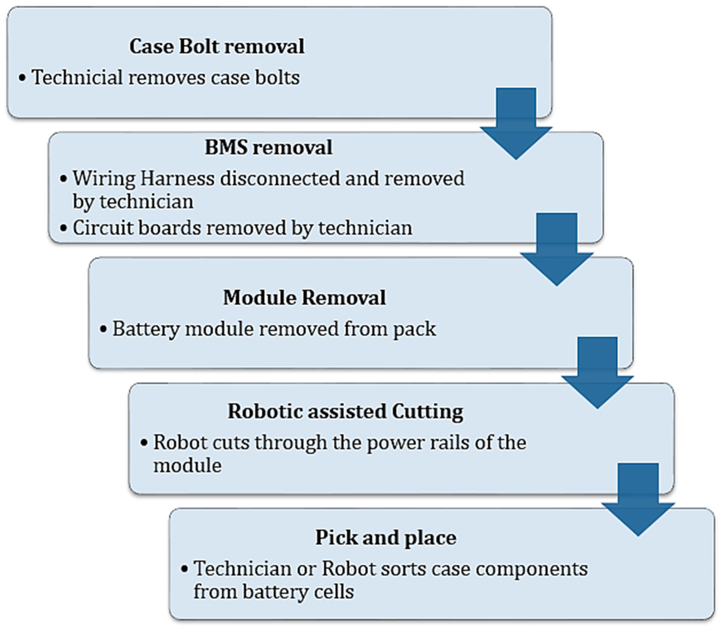
To reduce the economic burden associated with the disassembly process, a robotic method for automating or semi-automating the disassembly process was envisioned and tested in disassembling a representative battery module. This process was broken down into the following steps: process identification, suitable actions for robotic implementation, end-of-arm tooling design and control, development of a representative work piece, workspace layout, path planning, robotic modelling and simulation in MATLAB/Simulink, and experimental testing of the robotic system. The research focused on the implementation of a robot for disassembly, and the programming of the robot was done through direct inputs from the user with either the teach pendant [
14] or manual positioning [
14]. This methodology has the advantage that it can be done by technicians without prior knowledge since the path planning is situationally dependent. The human brain is quickly able to make decisions as to how a system needs to be assembled or disassembled, and this process is not easily automated due the highly complex nature of electro-mechanical systems. Research has been performed in the area of machine learning for the purpose of disassembly automation [
14]. Oak Ridge National Laboratory has also started introducing an automated disassembly line to make battery recycling safer and faster [
15]. Recently, some researchers reported studies on task planners for robot disassembly [
16] and human–robot collaboration [
17], but more research is required in this field.
In this study, a novel approach for disassembly of EV/HEV LIBs is presented based on the off-line simulation and path planning, as proposed to aid the implementation of the disassembly process. By using offline path planning, the precise control and tool paths of the robot can be predefined to maximize the efficiency of the required disassembly steps. In addition to this, both the robot dynamics and process time can be quantified to provide more insight into the state of the robot. By utilizing the CAD geometry models directly, offline simulation can be performed ahead of time, and allows the operator the ability to precisely define waypoints within the model that can allow for alternative disassembly techniques.
3. Experimental Design for Human–Machine Collaboration
As the pack level disassembly of the case would require an industrial robot with a large reach as well as a high payload, it was decided that for the purposes of this experiment the scope of implementing a robot would be on the module disassembly level. A FANUC LR-Mate 200iD/4S, six degree of freedom (6DOF) industrial robotic system was used with a maximum payload of 4 kg and maximum reach of 550 mm. This robot was chosen due to its precision and small size, as well as having the ability to communicate with an end effector through the input/output port on the upper arm.
To prove the suitability of a robot for the disassembly of an EV/HEV battery system, the benchmark operations of cutting and gripping were selected for evaluation. Both the cutter and gripper are required for the disassembly process by the robot, and they are add-ins to the robot. Fine motor function, such as disconnection of electrical connectors, were decided to be outside the scope of this experiment, as the inherent level of complexity and dexterity needed would require more specialized end-of-arm tooling. A more generalized assessment of the robot’s ability to perform gross motor function was chosen. The assessment was to be done for single end-effectors without accounting for the tool-change time, as a quick tool change and docking station could be implemented to automate the tool-change process. The total time for module disassembly would be evaluated based on the sum of the cutting and gripping operations, as well as any additional collaboration needed from a technician, such as fastener, connector, or harness removal. It is noted that the process analysis to find the total time of the disassembly process by robots is out of the scope of this paper.
End-of-arm tooling was a major focus of the experimental design, as the functional requirements defined in the robotic implementation stage required both highly precise motion and careful manipulation of components to prevent accidental shorting of the batteries or causing mechanical damage to the individual cells which could trigger a thermal event where explosion or fire could occur. Multiple modalities for the cutting tool were conceptualized, and a weighted decision matrix was used to select the best solution for implementation, design, and prototyping.
The first end effector to be evaluated was the cutting instrument, as this would be responsible for dismantling and separating the casing components from the individual battery cells. The cutting instrument would need to be compact, as the payload is limited to 4 kg, while maintaining the ability to cut through plastics and metal objects with both precision and speed. Cost was also considered a concern, as any additional cost of the robotic system would reduce the economic benefit. As listed in
Table 1, the three modalities of cutting investigated were a high-speed rotary cutter, a reciprocating saw mechanism, and a laser-cutting instrument.
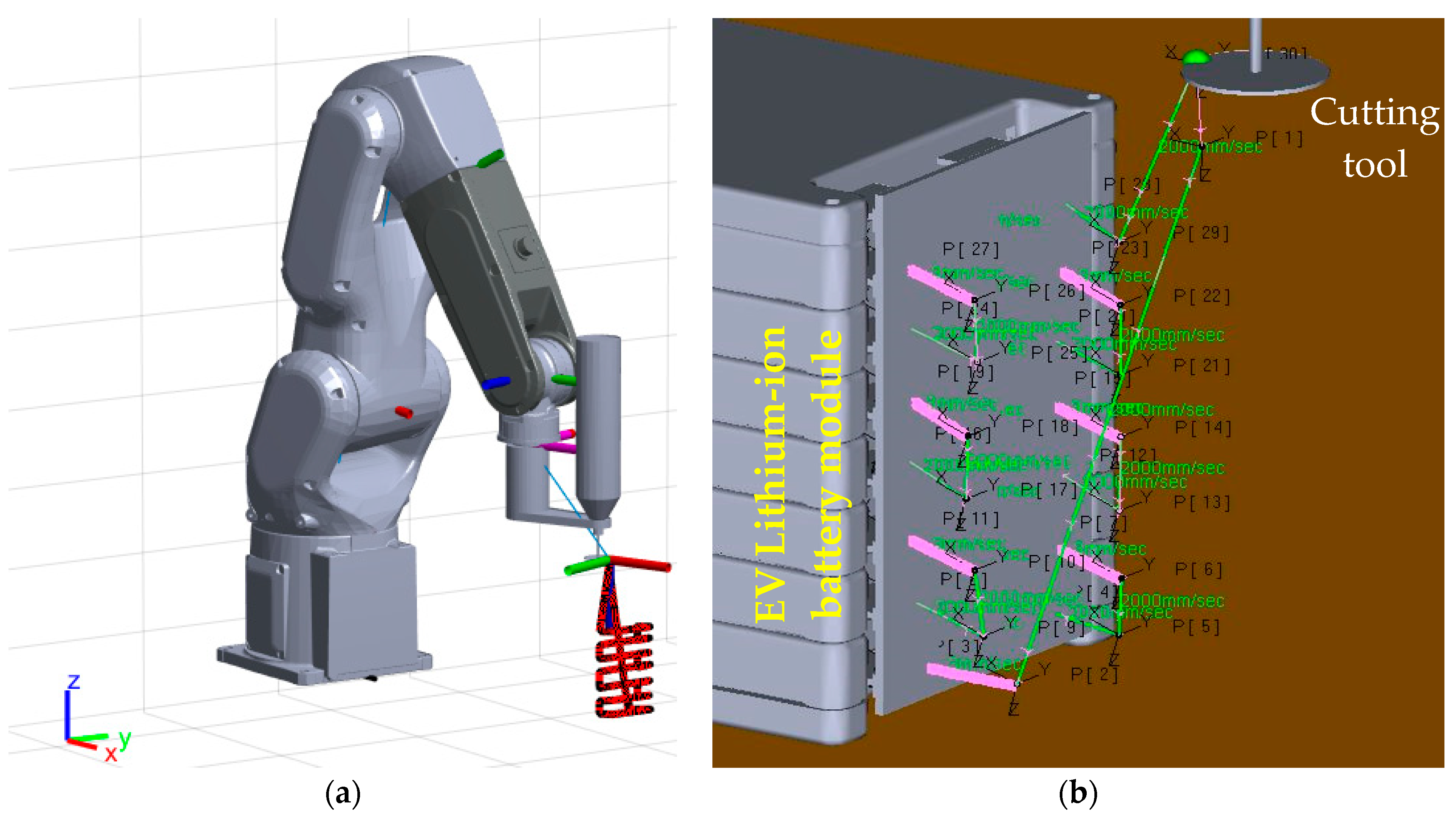
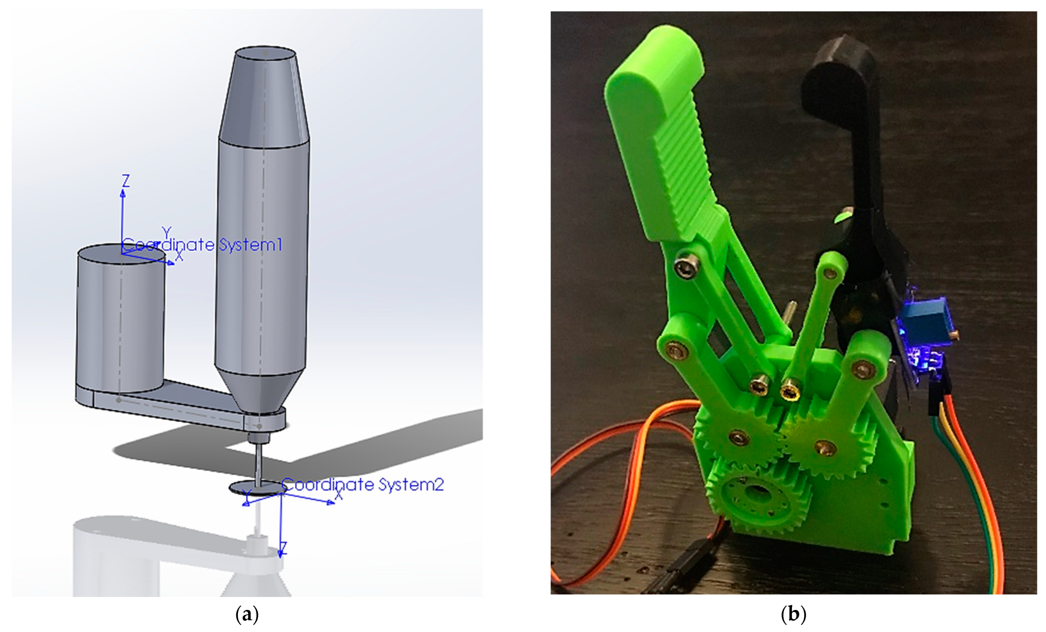
The high-speed rotary cutter was chosen due to the precision of cutting, compact size, and less technical difficulties, while still maintaining acceptable levels of heat generation and vibration transmission. Due to high-speed rotary cut-off tools being common, a Dremel 4000 was adapted to perform the cutting operations, as the motor and cutting speed were able to accommodate a wide range of materials and thicknesses. This was implemented, as shown in
Figure 3a, and used in the offline simulation to represent the geometric properties. Threads in the tool handle made cutting-tool integration with the robot secure and efficient. Since the state of the cutting tool only had one parameter that was controllable without modification of the tool, input/output states for the cutting tool can be controlled via a digital output as an on/off state from the upper arm in/out port communicating with a power relay to the tool.
After determining how to implement the cutting-tool control and designing custom mounting for it, the gripper was designed and built, as shown in
Figure 3b. Most robotic cells have gripper attachments, but few control the exact gripping pressure or force that grippers use to interface components. This is particularly important in the case of LIBs, as mechanical damage to the battery cell can cause internal short circuit, leading to thermal runaway [
18,
19] which is a major hazard presented by LIBs. For the gripper to not damage battery cells, force regulation became an important feature in the gripper design. The primary design for the gripper was based on a servo-actuated, gear-driven coupled planar linkage system with force feedback as the feature to be controlled. This was done through the implementation of a strain gauge into the gripper’s finger to measure the strain of the finger under load.
The finger was modeled as a fixed-free cantilever beam, where the load was applied at the tip of the finger. Knowing the geometric dimensions and the material properties of the as printed PLA, the Young’s modulus, the beams cross sectional properties, and the length of the beam were used to determine the bending stress at the base of the beam through the bending-stress equation in Equation (1).
The force was then calculated from Equation (2) to determine how the input mapped to the output of the system for setting up the error value.
The general design of the gripper was modeled as two gear-driven coupled four bar linkages with nearly parallel input links and four revolute joints to create a smooth motion. This allowed for a simplified actuation principle, as the system has only one degree of freedom being the input link angle if backlash and linkage compliance are assumed to be minimal. The general procedure was formulated similar to Ref. [
20].
After determining how to observe the forces, a mathematical model for the system was created to implement a feedback control law for the system. This was derived through the use of Lagrange’s equations. However, this yielded a sixth order nonlinear system of state equations for the planar linkage of the gripper. As a result of operating away from the nonlinear behavior, the system was approximated as a third order, linear, single input/single output (SISO) system, and the state space representation for the system dynamics was synthesized through the use of a least squares identification method. After synthesizing the state equations for use with the feedback error in the force, an infinite horizon linear quadratic regulator was implemented to control the system. For convenience and first try, the performance index, Q, and R matrices were selected as follows:
The optimal gains were calculated through the solution to the algebraic Riccati equation (ARE) Equation (4) and implemented using state variable feedback, as shown below in Equations (5) and (6).
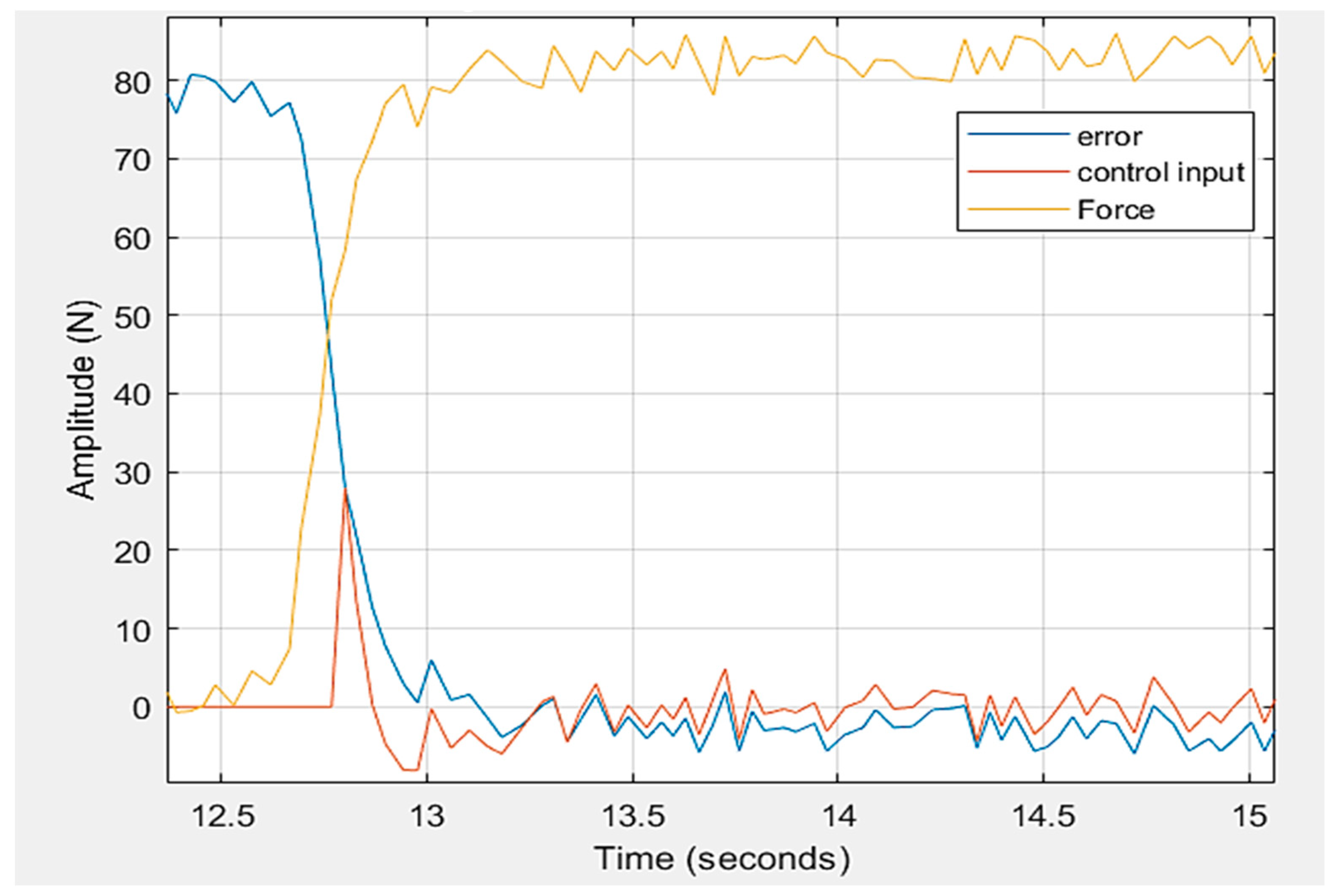
This was enough for the case of contacting the work piece. However, the initial conditions for solving the differential equations were not sufficient for the case of non-contact; thus, creating a two-step control strategy was required. As such, the gripper was modeled as a finite state machine with four states during operation. Due to the initial conditions not being available until after contact had been made with the work piece, four states were executed before the linear-quadratic regulator (LQR) control sequence was used. The first state was an idle state where the gripper was left in the state at which it last operated. After receiving an input signal from the robot during the pick and place sequence, the servo on the gripper moves the gripper to a limit open angle and sends a ready status to the robot in the form of a digital output. Once the robot moves the gripper into place for gripping the work piece, the robot then sends a start signal to the gripper to initiate a constant advance. After the contact force is detected via exceeding the contact force threshold, the initial conditions for the state equations are defined, and the LQR control sequence begins until the drop signal is given by the robot. The gripper controller was then tested for performance and implemented on the microcontroller through the Arduino toolbox in MATLAB, as shown in
Figure 4.
Due to hazards associated with disassembly of a real battery system, a representative battery module was created that mimicked the geometry, layout, and material composition of the battery module observed in the manual disassembly. The construction of the module consisted of a module frame, cell compartments that also functioned as cooling plates, top and bottom module covers, a front tab harness and connector, module frame bolts, and the module BMS. This was positioned on a flat surface within complete reach of the arm, where both cutting operations and pick and place could be completed. The representative module was made through the use of a 3D printer and assembled in a similar way to the actual module. The goal was to position the battery module in the workspace such that the tabs were accessible and that the individual cells could be lifted out from the top. Additionally, the module needed to remain in the same location during the cutting procedure; thus, the outline of the module location was marked, and the module was held in place with weights during the cutting operation.
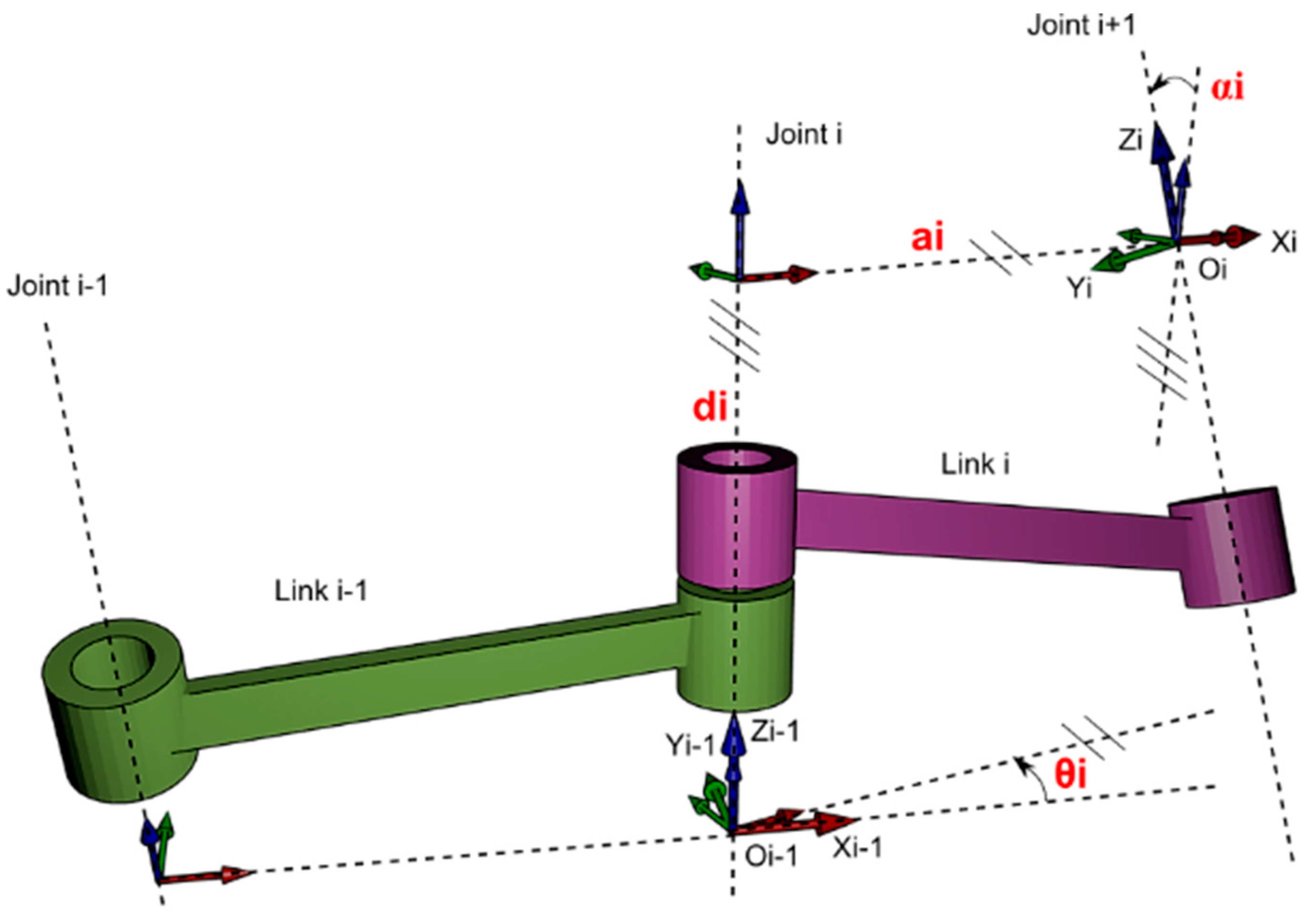
To develop the kinematic model of the robot, the Denavit–Hartenberg (DH) representation of a kinematic linkage chain can be used to model the system in terms of the DH parameters,
, as shown in
Figure 5 [
21].
For the case of the LR-Mate 200iD/4S, the DH parameters for the articulated robot are displayed in
Table 2. J1-6 are the six links of the robot, and J7 is the end effector.
Once the DH parameters are determined, the homogenous transformation matrix for each link can be computed as the product of the various rotation and translation matrices [
21], as shown in Equation (7).
These equations are fundamental to both the forward and inverse kinematics solver for determining or solving the position and pose of the robot in space. Forward kinematics uses joint states to calculate a position given a specified pose of the robot, whereas inverse kinematics solve for the joint states of a given end effector position and pose. Solving the inverse kinematic equations is more difficult, as there can be multiple solutions or no solutions to a given end effector position.
Once the DH parameters are known along with all the masses and lengths of the links and end effector, one can use the following equation to solve for the torques required to move the robot joints to a desired location, and from there along a desired trajectory. This equation is often called the robot equation or the dynamic model for a robot.
where
τ is the joint torques,
D is the inertia matrix for all the links,
h is Coriolis and centrifugal terms, and
C is the gravity terms.
MathWorks’ Robotics System Toolbox and Simscape Multibody Dynamics software packages were used in the MATLAB/Simulink environments to solve these equations. Both the forward and inverse kinematics/dynamics are simplified into blocks for use in solving the equations. There is a way to link CAD models directly into Simscape Multibody in the form of a Unified Robot Description Format (urdf) file. To import the robot model, the CAD model must be assembled, and the various coordinate systems, joint axes, inertia properties, and joint limits need to be defined during the setup of the urdf file. Once the urdf file is setup, it can be imported into MATLAB/Simulink, and motion analysis and offline path planning can be performed. Once the path planning was completed, simulation (
Figure 6a) was performed in MATLAB/Simulink to evaluate the motion of various joint states. The waypoints as well as pose information (
Figure 6b) were imported into MATLAB and fed into the inverse kinematics block in Simulink.
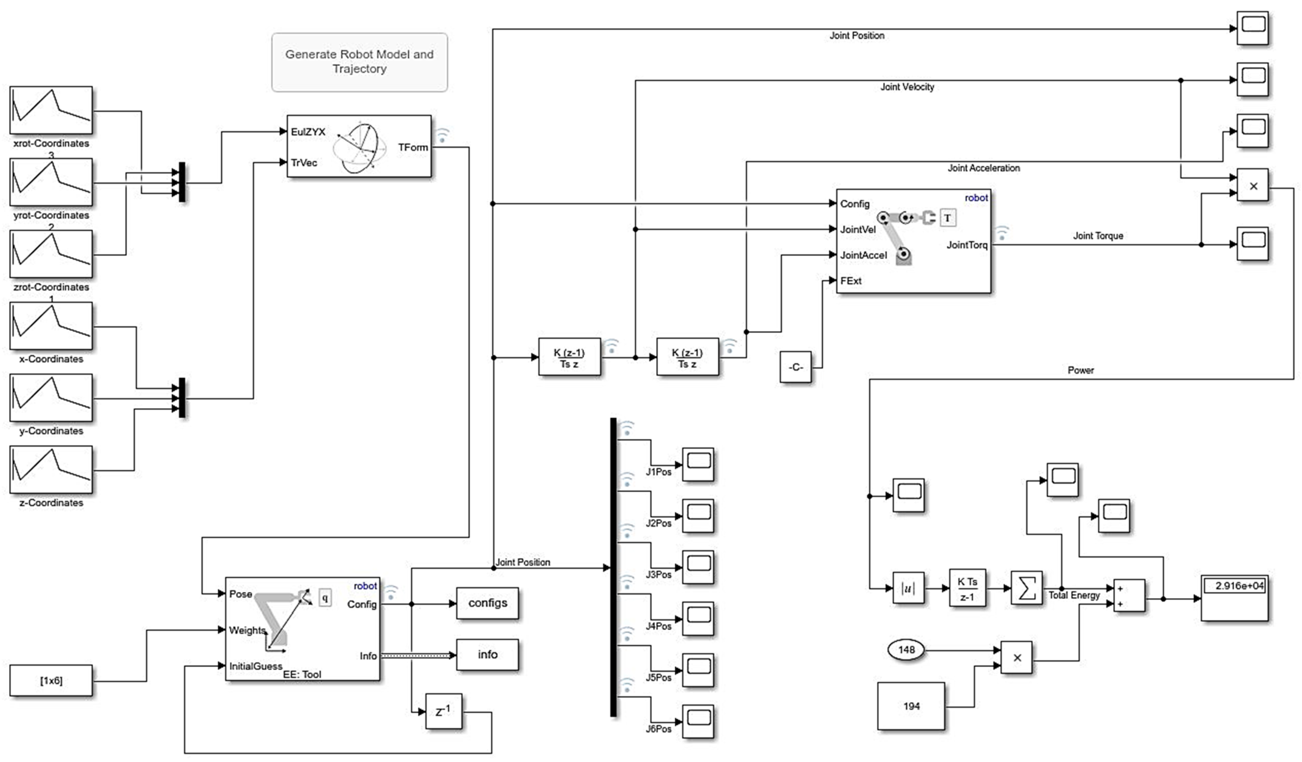
MATLAB utilizes the Levenberg–Marquardt algorithm (LMA) to solve the nonlinear least squares problem for the inverse kinematics. This method utilizes the minimization of the error in the joint configuration to that of the desired configuration to solve for the closest robot input joint angles to reach a target point [
20,
23]. This method is very robust and capable of solving complex motion tasks but can be slow to perform in real time. The Simulink block diagram for path definition and inverse kinematic is shown in
Figure 7.
4. Results and Discussion
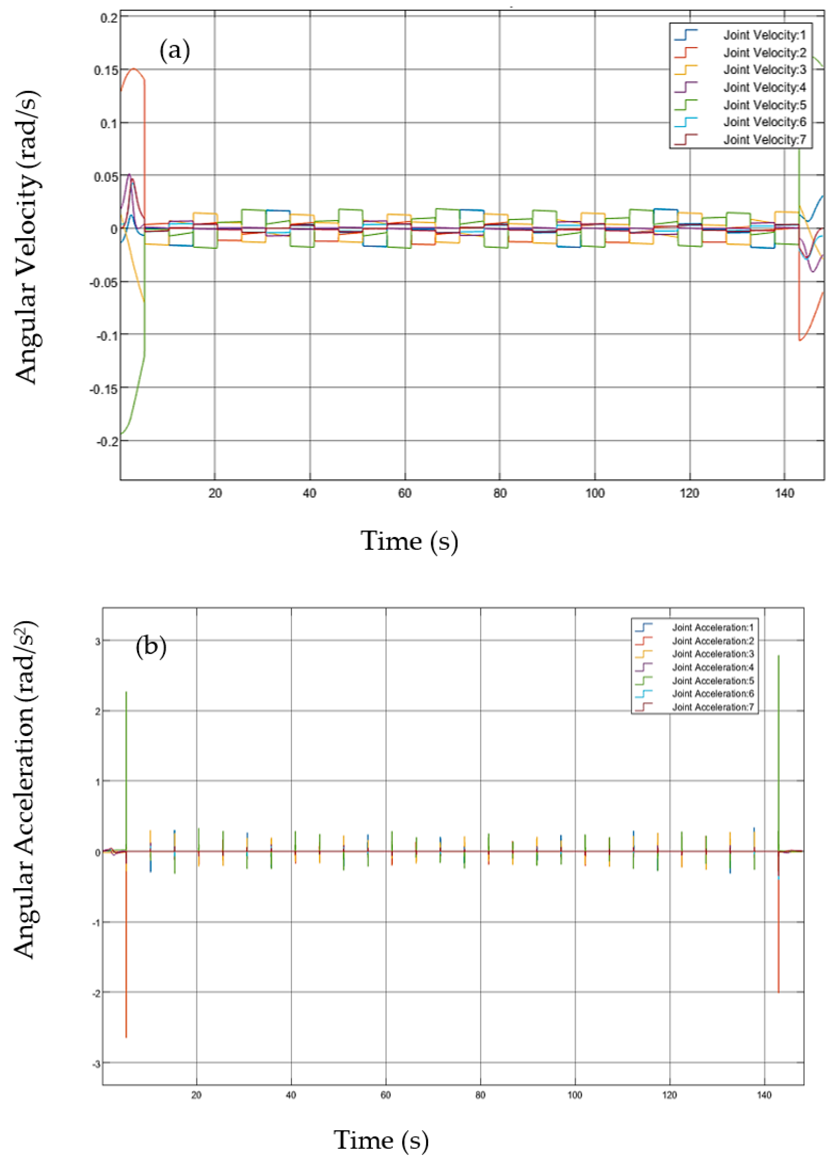
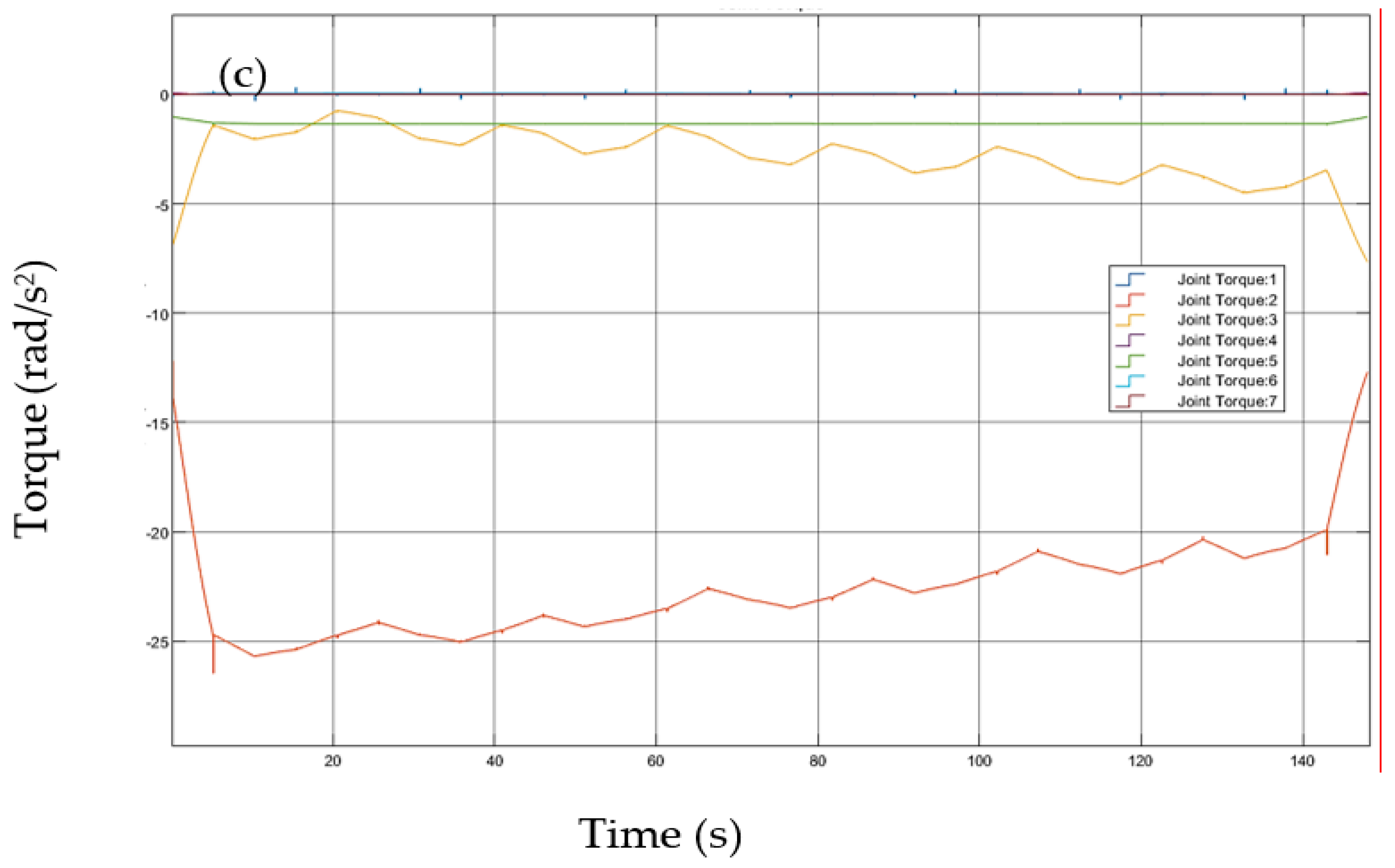
The velocity, acceleration, and torque were obtained from the offline simulation of cutting an EV battery module and then plotted for each robot joint, as demonstrated in
Figure 8, to study the involvement of each joint in the process. As seen in this figure, the angular velocities for joint 2 and joint 5 were highest, and the angular acceleration for joint 5 and joint 7 were highest at the beginning and end of the process, as compared to other joints. The angular velocity and angular acceleration of all joints are fluctuating at the middle of the process; however, their values are not significantly greater than zero. The highest torque also belongs to joint 7, followed by joints 3 and 5. The torque of other joints remains close to zero during the process. As a remarkable result, it was revealed that all velocities, accelerations, and torques can be easily handled by the robot, as shown in the
Figure 8. The error of values in
Figure 8 depends on the accuracy of the model and the model input parameters. Our estimation is that the error of the Simulink simulation for the velocity, acceleration, and torque is less than 2%.
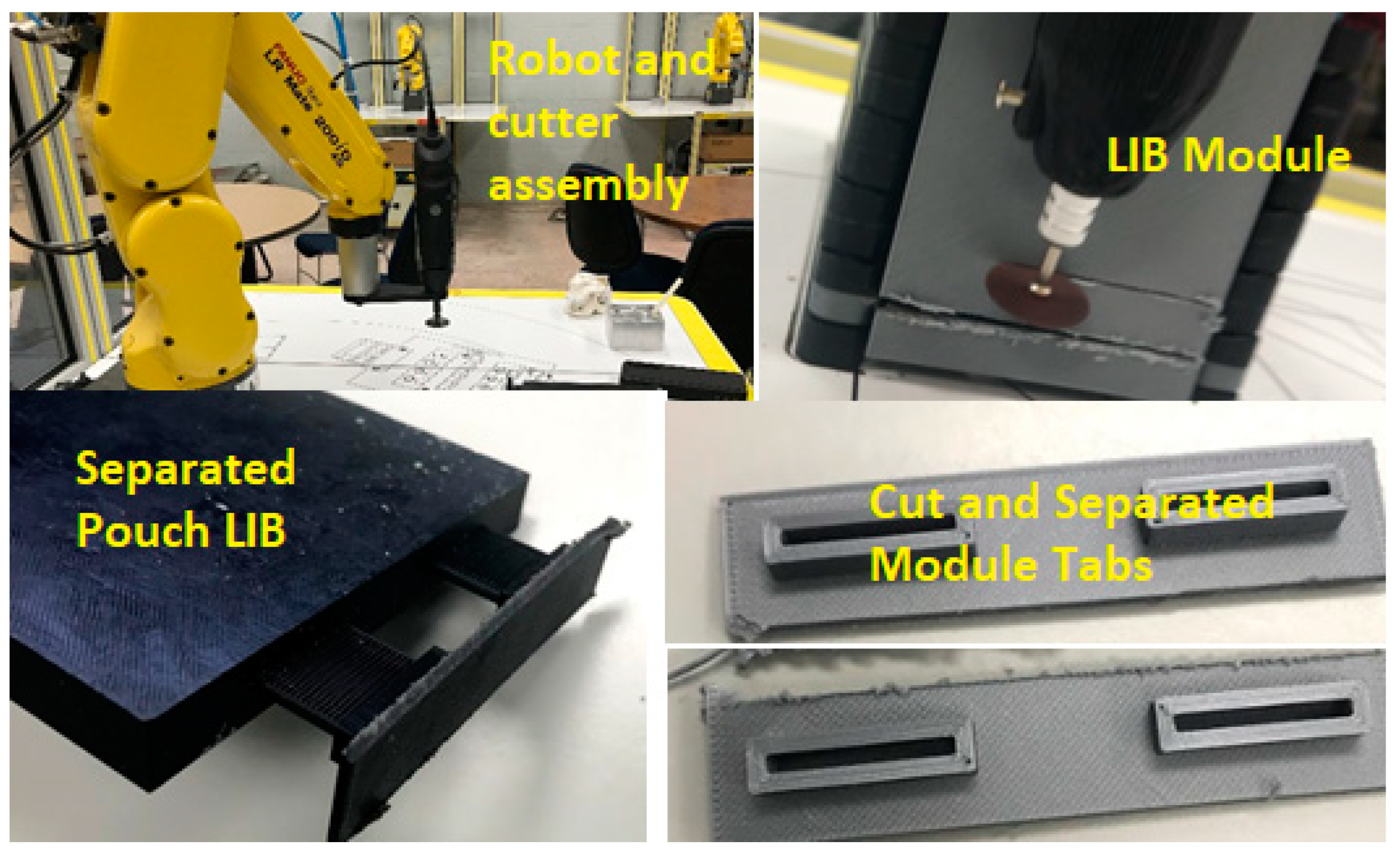
After the offline simulation was performed, the robot program was uploaded to the teach pendant to begin making the initial cuts experimentally. The cutting path was the first item to be tested in the experiment. The quality of the cut was based on two performance metrics:
All battery tabs in the EV battery modules (the LIB cells are the pouch type) were successfully cut by the robot (See
Figure 9). The cutting tool placed the cut with both accuracy and speed, performing the operation in 112 s (1:52 min). A technician completed this operation in 220 s (3:40 min) in the LIB recycling plant, which is 108 s (1:48 min) longer than the robot. This almost a 2X gain in speed efficiency. Thus, the disassembly process may be two times faster when a robot is incorporated into the process. However, more detailed time analysis is required for the final answer.
However, more importantly, the cutting path developed for the robot was more efficient, as it was a continuous cutting process and did not require the tool to be changed. Pick-and-place operations proved to be slightly lengthier and less successful in both time and performance compared to the technician. Therefore, the best option for disassembly of a LIB pack/module would be a human and robot collaboration, where the robot could make efficient cuts on the battery pack, and the technician/laborer could quickly sort the battery components and remove connectors or fasteners with which the robot would struggle. This is based on the results of the experiment, as the technician is capable of sorting through the components of the battery module 18 s faster than the robot and with higher rates of success.
The readers are referred to Ref. [
24], the publication of the authors at ASME IMECE-2019 for more information on the design aspect of this project. For more information about recycling lithium-ion batteries, the readers are recommended to look at Refs. [
25,
26,
27].


