Abstract
Three-phase inverters for photovoltaic grid-connected applications typically require some form of grid voltage phase-angle detection in order to properly synchronize to the grid and control real and reactive power generation. Typically, a phase-locked loop scheme is used to determine this real-time phase angle information. However, in the present work, a novel method is proposed whereby the phase angle of the grid can be accurately identified solely via the grid current feedback. This phase-angle observer is incorporated into a current controller which can manage the real and reactive power of the grid-connected PV inverter system. Moreover, the maximum power point of the photovoltaic arrays is achieved without using a DC–DC converter. The proposed method achieves the grid current and DC-link voltage control objectives without the knowledge of the grid information and without the need for a cascaded control scheme. The design of this combined observer/controller scheme is motivated and validated via a Lyapunov stability analysis. The experimental setup is prototyped utilizing a real-time Typhoon HIL 603 and National Instrument cRIO embedded controller in order to validate the proposed observer/controller scheme under different operation scenarios such as irradiation changes, frequency changes, reactive power injection, and operation with a distorted grid. The results show that the DC-link voltage and the active and reactive powers are well regulated from the proposed control scheme without the measurement of the grid phase and frequency.
1. Introduction
Solar energy is the most abundant and the cleanest form of renewable energy sources available in the world, which is used for a variety of applications, such as generation of electricity for domestic, commercial, or industrial applications [1,2]. Nowadays, photovoltaic (PV) generation is becoming a vital part of modern energy systems due to the cost reduction of manufacturing PV modules. Additionally, improvements in the energy extraction from solar panels has made PV generation more efficient and reliable than other generating sources [2,3]. Electrical power generated by PV array depends on the temperature and the solar irradiation, which has a strong nonlinear effect. Recently, the proliferation of installed grid-connected PV systems have begun to impact the stability of the power grid [4,5]. Thus, real-time control of grid-connected inverter systems has drawn recent attention in the literature [6,7]. The affects seen on the power system due to the stochastic nature of PV power outputs has drawn attention to the control system aspect of PV systems [8]. In the literature, connecting PV arrays to the utility grid has been accomplished in many forms and configurations [8,9]. Traditional PV systems utilize a two-stage power converter system with closed loop control schemes utilized throughout. A DC–DC converter is typically utilized as a first stage to regulate the voltage of the DC-link capacitor, thereby ensuring maximum power point operation for the PV arrays. The second stage is the DC–AC power converter, which injects AC power into the grid and/or supports a local load [10]. Using a two-stage topology results in a reduction of the system efficiency as well as an increase in the system cost [2]. For these reasons, a single-stage, three-phase, grid-connected PV system with maximum power point tracking (MPPT) and DC–AC converter will be used in this work.
Unintentional connection of the PV-based grid-connected inverter systems to the utility grid is undesirable as this could lead to system to instability [11]. Thus, in order to perform safe connection between the distribution generation unit (such as the PV-based inverter) and the grid, a synchronization unit is necessary to obtain the grid’s phase angle and frequency before connection to avoid an instantaneous out of phase connection. The main method that is used in the literature for this purpose is a Phase Locked Loop (PLL). Moreover, the grid’s information that is extracted from PLLs is used in the coordinate transformation in three-phase systems [12,13,14]. A PLL system is mainly integrated with the primary current control scheme as an outer loop, thus creating a cascaded control system [13,15]. In such cascaded schemes, the dynamics of the outer loop (in this case the PLL) should be slower (bandwidth) than the inner loop (current control loop) to maintain the stability of the system. On the other hand, the slow dynamic of a PLL-loop means delays in the detection of the grid’s phase and frequency, both of which are necessary for the current control loop. Moreover, adding a PLL loop to the main control loop will add more complexity to the system [16]. Many approaches have been proposed in the literature to improving the performance of the PLL schemes to address any potential instability issues resulting from the interaction between the PLL schemes and current control loop [17,18]. These challenges have motivated researchers to develop control schemes for grid-connected inverters that do not require a synchronization system such as PLLs [19,20,21,22]. For instance, the authors in [23] proposed a direct power controller for a single-phase grid-connected inverter without a PLL scheme. Moreover, we proposed in our work in [24] a method for a PLL-less current control scheme for three-phase, grid-connected inverters. Although these methods do not need a PLL scheme, they do not consider a grid-connected PV system or the additional dynamics this would entail. Previous studies [19,20,21,22,23,24] have considered a fixed dc voltage as an input. Hence, the dynamic of the PV panels, dc voltage regulator, and maximum power point tracking algorithm are not included in their control schemes.
A few works have investigated a PLL-less synchronization procedure for PV inverter systems. For example, in [25], the authors propose a current control scheme for single-phase PV inverter systems without a PLL scheme. The problem with this approach is that the control scheme has multiple current loops, which is problematic in managing the bandwidths with the various loops to insure the stability of the whole system. In [26], we propose a PLL-less current control scheme for PV inverter systems. Simulation results demonstrated the effectiveness of this approach to simultaneously control the grid current, DC-link voltage, and estimate the grid phase and frequency.
In this paper, a single-stage, three-phase, grid-connected photovoltaic system is controlled by a novel nonlinear current controller. The main contribution of the proposed controller is that the current tracking objective is achieved without knowledge of the grid phase angle and frequency. To do so, an estimated rotating reference frame (γδ-frame) is utilized [27]. Moreover, the proposed control scheme ensures that tracking of the DC-link capacitor reference voltage-generated from MPPT algorithm is achieved. This algorithm ensures the PV array(s) achieves their maximum power operating point. Within the control scheme, adaptive compensation terms facilitate the voltage and current tracking objectives and simultaneously account for the unavailable grid frequency and phase, hence eliminating the need for an additional feedback system for synchronization, such as a PLL. The voltage sensors required for PLL-type systems are expensive and introduce electrical noise and dc offsets, which must be compensated for in other ways.
The main contributions of the present work over our previous published work [26] and other works in the literature are:
- 1.
- The proposed controller/observer scheme eliminates the need for a cascaded control scheme. A cascaded approach is necessary in traditional control schemes for such an application to regulate the DC-link capacitor voltage, control the grid current, and determine the grid information extraction loop (PLL).
- 2.
- In terms of the control design, a new term has been added to both the DC-link voltage dynamics and grid current dynamics which accounts for un-modeled dynamics terms. Inclusion of these terms was motivated by validation experiments. Then, during the control design process, adaptive compensation terms have been included in the control to compensate for these uncertainties.
- 3.
- In terms of validation, an experimental setup has been prototyped to further validate the proposed scheme, including both control and observer aspects. A combination between Typhoon HIL [28,29,30,31] and National Instrument real time compact RIO has been used for this purpose. Furthermore, the proposed controller/observer scheme has been tested in different operating scenarios including sudden change to solar irradiance, grid frequency fluctuation, reactive power injection, and distorted grid utility.
2. System Model
A single-stage, three-phase, PV grid-connected inverter system with an inductive filter is shown in Figure 1. By applying Kirchhoff’s voltage law, the dynamic mathematical model for this system can be represented as
where are the phase voltages, are the phase currents, and are the voltages of the point of common coupling (PCC) at which the system is connected to the public utility grid. Assuming a switching average model, the three-phase inverter output voltages as the product to the DC-link voltage and the duty cycles of their respective switching legs can be represented as
where the duty cycles, . Moreover, assuming a balanced utility grid, the three-phase PCC voltages can be rewritten as
where is the amplitude of the PCC voltage, is the phase angle of the same voltage which will be donated as a grid phase angle, and to represent balanced three-phase voltages. By substituting (2) and (3) into (1), the three-phase grid current dynamics can be obtained as
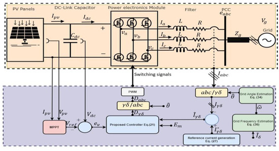
Figure 1.
Three-Phase Grid Connected PV System and proposed control scheme.
From Figure 1, the dynamic equation of the DC-link capacitor of the PV System can be obtained by applying Kirchhoff’s current law (KCL) at the capacitor node as follows:
where is the output current from PV panels, and is the DC input current to the inverter.
By using the standard Clarke and Park transformations, the -reference frame model for the system dynamics is obtained as
where is the grid frequency.
In this work, the grid angle is an unmeasurable and unknown parameter. Therefore, designing an observer for the grid angle is required to perform the transformations in the estimated reference frame [27]. This results in a rotating orthogonal axis system denoted as . After performing the transformation in the frame, the system shown in (6) can be written as
where is the error between the actual grid phase angle, and the observed phase angle will be defined later. In (7), is an unknown, slowly time-varying term added to compensate for any unknown disturbance and imperfect inverter modelling.
The dynamic equation of the DC-link capacitor in (5) can be modified by using the active power balance principle between the dc and ac system sides as follows:
where
and
Based on the Clarke transformation, (10) in the -frame can be written after some mathematical simplifications as
By performing the transformation of on (11), and after some mathematical simplifications, the power equation can be obtained in - estimated frame as follows:
Using (8), (9), and (12), the equation can be written as
Finally, the dynamic equation of the DC-link capacitor voltage for the PV inverter system in the estimated reference frame is obtained by substituting (13) into (5) as shown in (14):
where is a term added to compensate for any slowly time-varying, external, unknown disturbance.
3. Control System Development
The main objective of the proposed controller/observer scheme is designing duty cycle control signals of the PV single-stage, three-phase, grid-connected inverter system in the absence of the grid angle and frequency measurements. The and can follow their respective reference currents and , as Additionally, the PV array must operate at the maximum power point. To ensure this, the reference active current is designed in order to make sure that the DC-link capacitor voltage tracks its reference trajectory. Hence, as where the reference voltage trajectory is obtained from a standard MPPT algorithm. The subsequent stability analysis will prove that when the grid angle observer converges, , then , which means that the active and reactive power that will be injected into the grid are controllable. The following assumptions are made to facilitate this control development.
Assumption 1.
-frame currents are measurable. , are also measurable.
Assumption 2.
The nominal system parameters are known a priori.
Assumption 3.
The grid frequencyis unknown but is assumed to be a positive constant. Additionally, the grid phase angleis unknown.
Assumption 4.
The disturbance termsare assumed to be slowly time-varying; hence,
3.1. Error System Development
To facilitate the subsequent control development, the following current tracking errors are defined as
The tracking error dynamics of the DC-link voltage for the PV inverter system are defined as
Since the grid phase angle and frequency are unknown, the estimation error signals are defined as
Taking the time derivative of (15), pre-multiplying by , and utilizing the system dynamics from (7), the open loop error dynamics for the current are obtained as follows:
To simplify the analysis, assume that is small and centered about 0; hence, . Based on this assumption, (19) can be simplified in the following form:
3.2. Control Design
Motivated by the subsequent stability analysis and using the open loop error dynamics for the current in (20), the following duty cycle control inputs are defined as follows:
where is a positive control gain and is the estimation of the unknown disturbance . The update law of is designed based on the subsequent stability analysis and found to be as follows:
where is a positive estimation gain. The closed loop error dynamics of the current are obtained by substituting (21) into the open loop error dynamics in (20) as follows:
where is the estimation error defined as:
Taking the time derivative of (16), and pre-multiplying it by , and using the DC-link dynamic from (14) as well as the assumption , the open loop error dynamic of the DC- link voltage can be obtained as
Utilizing the tracking error of the current from (15), the above equation in (25) can be rewritten as
Motivated by subsequent stability analysis, can be designed based on the Equation (26) as follows:
where is a positive control gain and is the estimation of the unknown disturbance with the following updating law, which is obtained based on the subsequent stability analysis:
where is a positive estimation gain.
Remark 1.
is designed to stabilize the DC-link voltage and to make sure that the PV arrays are operating at their maximum power point. Moreover,could be selected to control the amount of the injected reactive power to the grid.
The closed loop error dynamics for can be obtained by substituting (27) into (25) as follows:
where is the estimation error of the unknown disturbance defined as
In order to design the grid phase-angle observer, the derivative of (18) is taken to obtain
Then, motivated by the subsequent stability analysis and the above equation in (31), the angle observer can be obtained after some mathematical operations as follows:
It is notable that the above update law for the grid angle observer is unrealizable due to the unknown and unmeasurable signals such as . To make this observer realizable and implementable, substitute term from the closed loop error dynamics of from (23) into (32) to obtain
Integrating both sides of (33) yields the following realizable form:
where (t) is the subsequently designed update law for the unknown grid frequency. Note that a realizable form of is still undefined, which is necessary for generating the duty cycle control inputs as shown in (21). For this reason, is subsequently designed. Given the relationship between these variables, this substitution is easily justified. Motivated by the stability analysis, the unrealizable design form for the grid frequency estimator is obtained as follows:
where is a positive estimator gain. To obtain a realizable form of this estimator, again the term from (23) should be used in (35) and then the integration of both sides is taken to obtain
3.3. Stability Analysis
Theorem 1.
The closed loop error dynamics from (23) and (29) ensure that the error signals defined in (15), (16), and (18) are regulated asas
Proof of Theorem 1.
To analyze the stability of the system, a Lyapunov function is chosen as follows:
Assumption 5.
in (37) is positive definite in the local region. Assuming thatis wrapped such that its effective domain is, the function is effectively globally positive definite.
The time derivative of is taken as follows:
Substituting the closed loop error dynamics from (23) and (29) as well as the update laws from (22), (28), (32), and (35) a long (31) into the above equation and simplifying, can be upper bounded as
By using the inequality , (t) can be further upper bounded as
It is clear that is a negative semi-definite function if and . From it is clear that . Since , from closed loop error dynamics for , and it is shown that . Moreover, and from Assumption 3, and therefore . Since and are bounded by assumption, then from (24) and (30) one can conclude that , . Since , from definition of it is clear that . Now, and from definition of , . Finally and , by Barbalat’s Lemma it is clear that as and thus as . □
4. Experimental Results
To validate the proposed controller, a hardware-in-the-loop setup has been implemented. The PV panels and the grid-connected inverter system shown in Figure 1 were emulated in Typhoon HIL603 hardware using the small-time step library. The control algorithm was implemented inside LabVIEW FPGA and then programmed into the National Instruments CompactRIO (cRIO) 9032. A digital output module NI 9401 on the cRIO is used to send the switching signals generated by the controller to the HIL603 via a digital input module. Moreover, the analog output module of the HIL603 is used to measure the emulated currents and the voltages of the inverter model and sends them to the controller via the analog input module NI 9222 of the cRIO. Analog input module NI 9015 is used to measure the DC-link voltage and PV current. Figure 2 shows the experimental setup components that are used in this C-HIL validation setup. Table 1 details the PV panels parameters that are used in Typhoon PV model generation. Table 2 summarizes the system parameters and the controller gains that are used throughout the following experiments. The controller gains have been found to meet the stability analysis conditions and have the best performance.
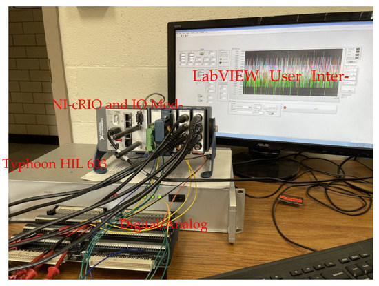
Figure 2.
C-HIL Experimental setup used for control system validation.

Table 1.
Photovoltaic Panels, System and Controller Parameters.

Table 2.
System Parameters and Controller gains.
4.1. Tracking Performance of Proposed Controller
In the first scenario, the tracking performance of the proposed controller/observer scheme, the PV system experiences standard atmospheric conditions for which the irradiation and the temperature are and , respectively. The -axis currents with their respective reference currents are shown in Figure 3 and Figure 4. It can be seen that -axis currents successfully follow the reference currents. The root mean square (RMS) of the steady-state errors for active and reactive currents and are calculated to be 0.45 A and 0.06 A, respectively. Figure 5 shows the voltage of the DC-link capacitor and the reference voltage generated by the MPPT algorithm (the MPPT algorithm will not be studied in this work). It is clear that the DC-link voltage tracks its reference voltage with the RMS steady-state error, which is around 0.1 V. The controller output (Duty cycle) that is needed for the proposed controller/observer scheme for the PV single-stage, three-phase, grid-connected inverter is shown in Figure 6. The observer of the grid angle follows the angle generated from PLL as shown in Figure 7. The PLL algorithm is used here only for comparison and is never used in the control scheme.
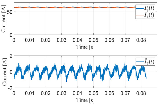
Figure 3.
Injected grid current in -axis for steady-state operation.
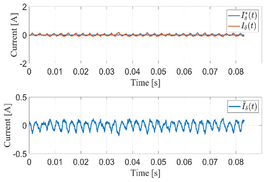
Figure 4.
Injected grid current in -axis for steady-state operation.
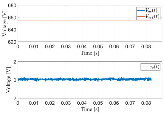
Figure 5.
DC-link bus performance in steady state operation.
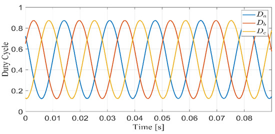
Figure 6.
Duty cycle for the inverter.
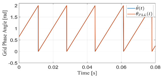
Figure 7.
Performance of the proposed observer and PLL-based grid phase angle.
Under real-world conditions, the irradiation of the sun is continuously changing, which affects the output power of the PV panels. For this reason, the controller for such a system should be tested in the presence of irradiation changes. In this test, a sudden change in irradiation occurs at 3.6 s. from to . It can be seen that the -axis currents follow the reference currents smoothly and very quickly, as shown in Figure 8. Moreover, the DC-link voltage follows the reference voltage , which is generated from the MPPT algorithm, as shown in Figure 9. It is clear from this figure that the voltage control works very well. Figure 10 shows the output active power changes based on the irradiation step change. It is clear that the active power is reduced according to irradiation drop with smooth performance. Figure 11 demonstrates the tracking performance of the proposed grid phase angle and frequency observer scheme. The grid frequency is changed from to and then back to . It is seen that the proposed observer estimates the grid frequency without any over or undershoot.
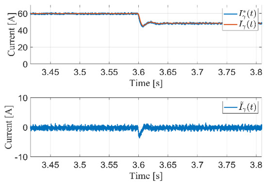
Figure 8.
Current tracking performance for irradiation change from 1000 to 800.
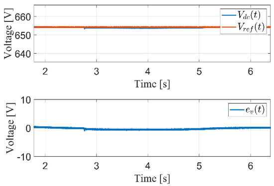
Figure 9.
DC-link bus performance for irradiation changes from 1000 to 800 .
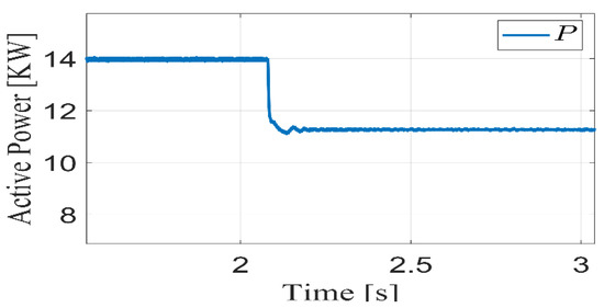
Figure 10.
Active power performance during the irradiance changes.
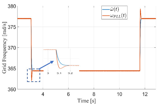
Figure 11.
Tracking performance of the estimation of the grid frequency.
4.2. Proposed Controller Performance under Low- Voltage Ride-Through (LVRT) Scenario
Generally, LVRT is a common disturbance in the utility grid voltage which creates a severe operating condition for PV grid-connected inverters. An LVRT scenario has been employed to test the robustness of our proposed controller/observer scheme against this type of grid disturbance. This scenario is emulated by dropping the magnitude of the grid voltage from to for . Figure 12 shows the active power injected into the grid during this kind of disturbance along with the grid voltage profile. As can be seen, the controller maintains constant power output to the grid. Since the grid voltage decreases, the only way to keep the power constant is to increase the current supplied from the PV system. In this case, the current limiter is added to the circuit in order to keep the current within the PV panel-rated current if the voltage drops to severe levels. Figure 13 shows the tracking performance of the injected current in this operating point.
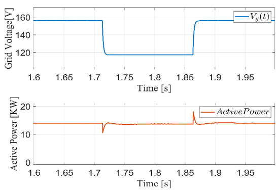
Figure 12.
System performance due to LVRT scenario (Voltage drop from 110 Vrms to 80 Vrms).
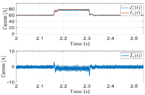
Figure 13.
Current tracking performance corresponding to LVRT condition.
4.3. Proposed Controller Performance in the Presence of Harmonic Rich Grid
Harmonics are very common in grid voltage. The effect of these harmonics on renewable based power systems must be tested. In this scenario, the gird voltage with a Total Harmonics Distortion (THD) of 16% is used in order to demonstrate the capability of the proposed controller to harvest the maximum power from the PV panels and to inject power into the grid. Figure 14 shows the active power that is injected into the grid. Figure 15 shows the controller performance—in this case, in terms of the error signals for the injected currents and DC-Link voltage. Moreover, Figure 16 shows the proposed observer performance for the phase angle and frequency of the grid voltage.
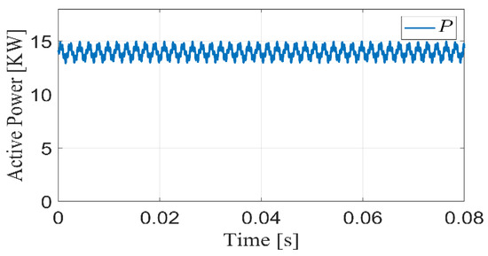
Figure 14.
Active power injected into the grid under distorted grid.
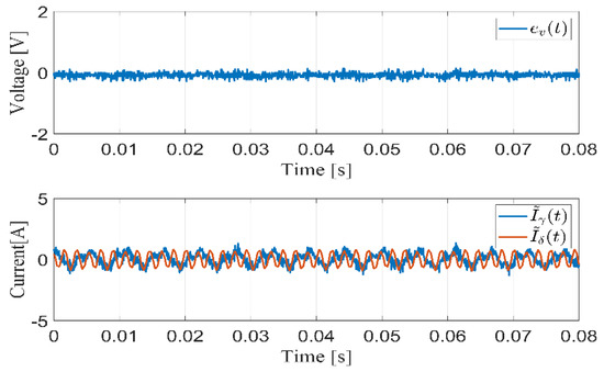
Figure 15.
Steady-state error signals under distorted grid conditions.
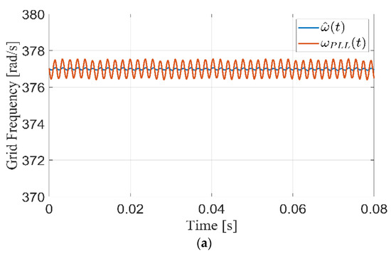
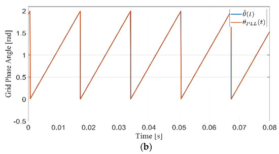
Figure 16.
Steady-state observer performance under distorted grid (a) grid frequency [rad/s] (b) grid phase angle [rad].
4.4. Proposed Controller Performance under Reactive Power Injection Condition
The proposed controller has been designed to handle both active power harvesting and reactive power injection operating conditions. In this test, the reactive power injection condition is applied by increasing the q-axis reference current to inject 7.5 KVAR into the grid. Figure 17 shows the performance during the injection condition. It is seen that the reactive power is injected with a small percentage overshoot of less than 5%. Moreover, Figure 17 shows the power factor at the grid side before and after reactive power injection. The power factor is unity before the injection instant and is calculated to be 0.86 after the injection of reactive power since the phase angle between the voltage and current is around .
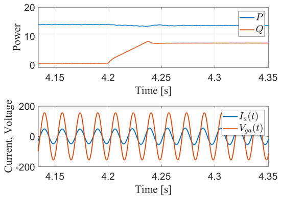
Figure 17.
Active and reactive power performance during reactive power injection condition and power factor change due to the injection.
5. Conclusions
A current and voltage control scheme for a single-stage, PV grid-connected, three-phase inverter has been proposed. The proposed controller/observer scheme achieves the grid current and DC-link voltage control objectives without the knowledge of the grid information and without the need for a cascaded control scheme. Moreover, self-synchronization between the PV inverter and the grid has been guaranteed without using a PLL scheme or a synchronization unit. The proposed scheme adaptively estimated the grid phase angle and frequency. The controller and estimation schemes are validated by a Lyapunov stability analysis, and the closed loop stability has been proven. From the hardware-in-the loop experimental results, it is clear that the proposed scheme has acceptable performance for both transient and steady-state operations. Many other real-world test cases have also been evaluated. In all cases, the proposed scheme demonstrated acceptable operations in the presence of missing system information.
Author Contributions
Conceptualization, M.L.M. and M.A.; methodology, M.L.M. and M.A.; software, M.A.; validation, M.A.; formal analysis, M.A.; investigation, M.A. and M.L.M.; resources, M.L.M.; data curation, M.A.; writing—original draft preparation, M.A.; writing—review and editing, M.L.M.; visualization, M.A.; supervision, M.L.M.; project administration, M.L.M.; funding acquisition, M.L.M. All authors have read and agreed to the published version of the manuscript.
Funding
This research received no external funding.
Institutional Review Board Statement
Not applicable.
Informed Consent Statement
Not applicable.
Data Availability Statement
Not applicable.
Conflicts of Interest
The authors declare no conflict of interest.
References
- Rashid, M.H. Alternative Energy in Power Electronics; Butterworth-Heinemann: Oxford, UK, 2014; pp. 1–363. [Google Scholar]
- Kouro, S.; Leon, J.I.; Vinnikov, D.; Franquelo, L.G. Grid-Connected Photovoltaic Systems: An Overview of Recent Research and Emerging PV Converter Technology. IEEE Ind. Electron. Mag. 2015, 9, 47–61. [Google Scholar] [CrossRef]
- Hernández-Callejo, L.; Gallardo-Saavedra, S.; Alonso-Gómez, V. A review of photovoltaic systems: Design, operation and maintenance. Solar Energy 2019, 188, 426–440. [Google Scholar] [CrossRef]
- Rahman, S.; Saha, S.; Islam, S.N.; Arif, M.T.; Mosadeghy, M.; Haque, M.E.; Oo, A.M.T. Analysis of Power Grid Voltage Stability With High Penetration of Solar PV Systems. IEEE Trans. Ind. Appl. 2021, 57, 2245–2257. [Google Scholar] [CrossRef]
- You, S.; Kou, G.; Liu, Y.; Zhang, X.; Cui, Y.; Till, M.J.; Yao, W.; Liu, Y. Impact of High PV Penetration on the Inter-Area Oscillations in the U.S. Eastern Interconnection. IEEE Access 2017, 5, 4361–4369. [Google Scholar] [CrossRef]
- Joshi, J.; Swami, A.K.; Jately, V.; Azzopardi, B. A Comprehensive Review of Control Strategies to Overcome Challenges During LVRT in PV Systems. IEEE Access 2021, 9, 121804–121834. [Google Scholar] [CrossRef]
- Singhal, A.; Ajjarapu, V.; Fuller, J.; Hansen, J. Real-Time Local Volt/Var Control Under External Disturbances With High PV Penetration. IEEE Trans. Smart Grid 2019, 10, 3849–3859. [Google Scholar] [CrossRef] [Green Version]
- Romero-Cadaval, E.; Francois, B.; Malinowski, M.; Zhong, Q. Grid-Connected Photovoltaic Plants: An Alternative Energy Source, Replacing Conventional Sources. IEEE Ind. Electron. Mag. 2015, 9, 18–32. [Google Scholar] [CrossRef]
- Basu, T.S.; Maiti, S. A Hybrid Modular Multilevel Converter for Solar Power Integration. IEEE Trans. Ind. Appl. 2019, 55, 5166–5177. [Google Scholar] [CrossRef]
- Chen, L.; Amirahmadi, A.; Zhang, Q.; Kutkut, N.; Batarseh, I. Design and Implementation of Three-Phase Two-Stage Grid-Connected Module Integrated Converter. IEEE Trans. Power Electron. 2014, 29, 3881–3892. [Google Scholar] [CrossRef]
- Dhlamini, N.; Chowdhury, S.P.D. Solar Photovoltaic Generation and its Integration Impact on the Existing Power Grid. In Proceedings of the 2018 IEEE PES/IAS PowerAfrica, Cape Town, South Africa, 28–29 June 2018; pp. 710–715. [Google Scholar]
- Golestan, S.; Guerrero, J.M.; Musavi, F.; Vasquez, J.C. Single-Phase Frequency-Locked Loops: A Comprehensive Review. IEEE Trans. Power Electron. 2019, 34, 11791–11812. [Google Scholar] [CrossRef]
- Zou, Z.; Liserre, M. Modeling Phase-Locked Loop-Based Synchronization in Grid-Interfaced Converters. IEEE Trans. Energy Convers. 2020, 35, 394–404. [Google Scholar] [CrossRef]
- Hui, N.; Feng, Y.; Han, X. Design of a High Performance Phase-Locked Loop With DC Offset Rejection Capability Under Adverse Grid Condition. IEEE Access 2020, 8, 6827–6838. [Google Scholar] [CrossRef]
- Huang, L.; Xin, H.; Li, Z.; Ju, P.; Yuan, H.; Lan, Z.; Wang, Z. Grid-Synchronization Stability Analysis and Loop Shaping for PLL-Based Power Converters With Different Reactive Power Control. IEEE Trans. Smart Grid 2020, 11, 501–516. [Google Scholar] [CrossRef]
- Sun, Y.; de Jong, E.C.W.; Wang, X.; Yang, D.; Blaabjerg, F.; Cuk, V.; Cobben, J.F.G. The Impact of PLL Dynamics on the Low Inertia Power Grid: A Case Study of Bonaire Island Power System. Energies 2019, 12, 1259. Available online: https://www.mdpi.com/1996-1073/12/7/1259 (accessed on 2 April 2019). [CrossRef] [Green Version]
- Šimek, P.; Valouch, V. Cascaded Delayed Signal Cancellation Based Pre-Filtering Technique to Improve Frequency Locked Loop for Grid Synchronization. In Proceedings of the 2019 International Conference on Electrical Drives & Power Electronics (EDPE), The High Tatras, Slovakia, 24–26 September 2019; pp. 391–396. [Google Scholar]
- Hu, W.; Wu, Y.; Shen, Y.; Yang, F.; Quan, X.; Deng, F.; Zou, Z. One-Step-Prediction Discrete Observer Based Frequency-Locked-Loop Technique for Three-Phase System. IEEE Access 2021, 9, 95401–95411. [Google Scholar] [CrossRef]
- Zhong, Q.; Nguyen, P.; Ma, Z.; Sheng, W. Self-Synchronized Synchronverters: Inverters Without a Dedicated Synchronization Unit. IEEE Trans. Power Electron. 2014, 29, 617–630. [Google Scholar] [CrossRef]
- Perenyi, C.; Alqatamin, M.; Harzig, T.; McIntyre, M.; Grainger, B.M. System Frequency Dynamic Response of a Novel, Self-Synchronizing Inverter in a High Renewable Penetration Grid. In Proceedings of the 2020 22nd European Conference on Power Electronics and Applications (EPE’20 ECCE Europe), Lyon, France, 7–11 September 2020; pp. 1–10. [Google Scholar]
- Konstantopoulos, G.C.; Zhong, Q.; Ming, W. PLL-Less Nonlinear Current-Limiting Controller for Single-Phase Grid-Tied Inverters: Design, Stability Analysis, and Operation Under Grid Faults. IEEE Trans. Ind. Electron. 2016, 63, 5582–5591. [Google Scholar] [CrossRef] [Green Version]
- Guo, X.; Liu, W.; Zhang, X.; Sun, X.; Lu, Z.; Guerrero, J.M. Flexible Control Strategy for Grid-Connected Inverter Under Unbalanced Grid Faults Without PLL. IEEE Trans. Power Electron. 2015, 30, 1773–1778. [Google Scholar] [CrossRef] [Green Version]
- Ma, J.; Song, W.; Jiao, S.; Zhao, J.; Feng, X. Power Calculation for Direct Power Control of Single-Phase Three-Level Rectifiers Without Phase-Locked Loop. IEEE Trans. Ind. Electron. 2016, 63, 2871–2882. [Google Scholar] [CrossRef]
- Alqatamin, M.; Latham, J.; Smith, Z.T.; Grainger, B.M.; McIntyre, M.L. Current Control of a Three-Phase, Grid-Connected Inverter in the Presence of Unknown Grid Parameters Without a Phase-Locked Loop. IEEE J. Emerg. Sel. Top. Power Electron. 2021, 9, 3127–3136. [Google Scholar] [CrossRef]
- Tsang, K.M.; Chan, W.L.; Tang, X. PLL-less single stage grid-connected photovoltaic inverter with rapid maximum power point tracking. Solar Energy 2013, 97, 285–292. [Google Scholar] [CrossRef]
- Alqatamin, M.; Bhagwat, B.; Hawkins, N.; Latham, J.; McIntyre, M.L. Self-Synchronizing Current Control for Single-Stage Three-Phase Grid-Connected Photovoltaic Systems. In Proceedings of the 2020 American Control Conference (ACC), Denver, CO, USA, 1–3 July 2020; pp. 192–197. [Google Scholar]
- Krause, P.; Wasynczuk, O.; Sudhoff, S.D.; Pekarek, S. Reference-Frame Theory. In Analysis of Electric Machinery and Drive Systems; Wiley: Hoboken, NJ, USA, 2013; pp. 86–120. [Google Scholar] [CrossRef]
- Goli, C.S.; Manjrekar, M.; Sahu, P.; Chanda, A.; Essakiappan, S. Implementation of Stationary and Synchronous Frame Current Regulators for Grid Tied Inverter using Typhoon Hardware in Loop System. In Proceedings of the 2021 IEEE 12th International Symposium on Power Electronics for Distributed Generation Systems (PEDG), Chicago, IL, USA, 28 June–1 July 2021; pp. 1–8. [Google Scholar]
- He, X.; Geng, H. PLL Synchronization Stability of Grid-Connected Multi-Converter Systems. IEEE Trans. Ind. Appl. 2021, 58, 830–842. [Google Scholar] [CrossRef]
- Achlerkar, P.; Panigrahi, B.K. Dynamic Harmonic Domain Modeling and Stability Augmented Design of Inverter Interface to Weak and Unbalanced Grid. IEEE Trans. Power Deliv. 2021, 1. [Google Scholar] [CrossRef]
- Gautam, G.; Poddar, S. Real Time Simulation of 3-φ Grid-Connected Converter with Real and Reactive Power Control Under Different Grid Fault Conditions. In Proceedings of the Advances in Smart Grid Automation and Industry 4.0, Singapore, 29 May 2021; Reddy, M.J.B., Mohanta, D.K., Kumar, D., Ghosh, D., Eds.; Springer: Singapore, 2021; pp. 601–612. [Google Scholar]
Publisher’s Note: MDPI stays neutral with regard to jurisdictional claims in published maps and institutional affiliations. |
© 2022 by the authors. Licensee MDPI, Basel, Switzerland. This article is an open access article distributed under the terms and conditions of the Creative Commons Attribution (CC BY) license (https://creativecommons.org/licenses/by/4.0/).