Abstract
The application of the nanosecond pulsed electric field (nsPEF) for biomedical treatments has gained more interest in recent decades due to the development of pulsed power technologies which provides the ability to control the electric field dose applied during tests. In this context, the proposed paper describes a new architecture of solid-state high-voltage pulse generators (SS-HVPG) designed to generate fully customised sequences of quasi-rectangular pulses. The idea is based on the combination of semiconductor switches (IGBT/MOSFET) known for their flexibility and controllability with special magnetic switches to build compact and modular generators. The proposed structure is inspired by the most known pulse generator of Marx, but mixes its two variants for negative and positive polarities. Thus, the polarity of the generated pulses can be freely selected. In addition to that, the use of IGBTs/MOSFET ensures a tunable repetition rate and pulse width. The capacitors are charged via a series of magnetic switches and a flyback DC–DC converter which provides fast and efficient charging and also an adjustable amplitude of the output pulses. The design can be easily simplified giving two other modified structures, based on the same idea, for mono-polar operating (only positive or only negative pulses) with a reduced number of switches. A SPICE simulation of the generator and results of experimental tests carried out on a three stages generator are presented. The obtained results confirm the operating principle and the claimed performances of the new structure.
1. Introduction
Regardless of the huge number of works treating the effects of pulsed electric field on living cells [1,2,3,4], the subject has not been completely covered due to various scientific fields interfering and the numerous correlated phenomena associated with it, which makes it a very challenging subject for studies. However, it is rewarded by a variety of applications, a vast array of perspectives, and the potential achievements that it may lead to, such as cancer treatment [5,6,7], gene transfer [8,9], medical imaging [10], and disinfection [11], etc. All these applications share the same idea of applying a specific electric field pulse to the treated sample using a dedicated delivery system. These pulses are generated using a high-voltage pulse generator which defines the main characteristics of the pulses, such as amplitude, polarity, pulse duration, and repetition rate. Thus, the success of these applications depends deeply on the quality of the generated pulses, which makes the pulse generator a key factor in any research work in this field [12].
For this reason, many studies were carried out to develop robust, efficient, flexible, and easy-to-use generators. Many of them are based on the classical architecture of a Marx generator (shown in Figure 1), such as in [13,14,15,16,17], transmission lines and Blumlein-based generators [18,19], RLC pulse-forming networks [20], and pulse transformer-based generators [21].
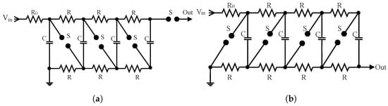
Figure 1.
Classical Marx generator: (a) positive polarity; (b) negative polarity.
Besides biomedical treatments, pulsed power technologies have many other applications, such as plasma science [22,23,24], industrial process [25], ultrawideband radiation, and EMP generation [26,27,28,29]. All these applications use architectures similar to the previously mentioned high-voltage pulse generators.
It may be noted that much of this work treats partially controlled generators. In other words, they provide control over some parameters of the pulse, but not all. In particular, only a small part of the works proposes topologies that help to change the polarity of the pulse. Even if this is possible, it is at the expense of complex structures using a large number of switches, which increases the cost, complexity, and possibility of generator failure.
For instance, in [30], the authors propose a modular high-voltage pulse generator which has the ability to generate pulses with controllable pulse width and polarity. However, each stage of the designed generator consists of two capacitors, eight IGBTs, and ten diodes, making the design of the power board, its gate driving circuit, and the control unit very complicated and expensive.
Another example can be found in [31] where the difference of outputs of two Marx generators is applied to the load to create a bipolar pulse depending on the delay between pulses. This structure has fewer semiconductor switches compared to the previous one, but a large part of the stored energy is lost and just a small part is transferred to the load. This leads to a poor power efficiency.
The new generator proposed in this paper offers the ability to control the polarity, amplitude, duration, and repetition rate of pulses using a reduced number of switches, high-voltage gain, and a modular semiconductor structure. It is clearly superior compared to the above mentioned devices.
The following sections of the paper discuss the operating principle of this design, supported by SPICE simulation and experimental studies.
2. Structure of the New Generator
The general circuit of the proposed generator is presented in Figure 2. It consists of two main parts. The first one is the charging circuit, which provides the second stage with a conditioned power from a low voltage power supply. The second part can be described as the pulse modulator, which ensures the generation of required pulses with configurable repetition rate, pulse width, amplitude, and polarity.
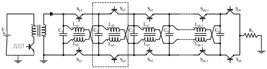
Figure 2.
New structure of fully controlled bipolar Marx generator.
2.1. Charging Stage
In the proposed structure, the capacitors are charged using a fly-back DC–DC converter. It is connected to the pulse modulator via a diode to prevent reverse power flowing. The voltage across the first capacitor is sensed and regulated. In this way, it is possible to control the pulse amplitude by controlling the charging voltage of the capacitors. The charging system also ensures high power efficiency, the only losses present at the level of the inductors’ resistance, the magnetic core, and at the semiconductor switches. Thus, the power efficiency is substantially higher than classical solutions with resistive charging which cannot exceed 50% due to joule losses such as in [31].
2.2. Pulse Modulator
The pulse modulator is developed by combining two classical structures of Marx generator for positive and negative polarities (Figure 1) with two modifications: substituting the spark gaps by IGBTs/MOSFETs and the charging resistors by magnetic switches. The modulator is built on N modules—each one contains a storage capacitor, two IGBTs, and a magnetic switch. An example module is marked with the dash-dotted box in Figure 2.
The magnetic switches used in the design differ from the conventional ones which are based on the magnetic saturation to reproduce the behaviour of a switch, e.g., in [32,33,34]. The proposed one consists of two identical, tightly coupled inductors. In reality, the inductors are never perfectly coupled. If two identical inductances L are coupled with a coupling factor k, as shown in Figure 3, then they can be conceptually divided into two components: two perfectly coupled inductors with , modeling the common flux that passes through both coils, and two independent inductors , modeling the leakage flux. If electric currents pass through both of them, the induced magnetic fluxes can add or subtract. When the currents are the same and the fluxes subtract, canceling each other, the total inductance collapses and both inductances can be considered as short circuits (just is visible). When the fluxes add, the total inductance will be doubled, and so the impedances of both coil. Thus, the two inductors can be considered as open circuit. Directions of currents in inductors can be controlled with solid-state switches. In this way, it is possible to connect the two coils to obtain a very low impedance during the charging phase and very high impedance during the discharging phase.
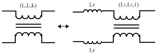
Figure 3.
Magnetic switch model.
The choice of coupled inductors as magnetic switch has many advantages:
- They provide a charging path for capacitors without passing by the load, which eliminates the dependency between the charging time and the load. In other words, the repetition rate becomes completely independent from the load;
- They reduce the charging time and raise the repetition rate of the generator;
- They increase the power efficiency of the generator in comparison to resistive charging;
- They increase robustness and decrease the cost, reducing the probability of failures caused by resistors overheating and reducing the number of semiconductor switches.
Nevertheless, for a proper functioning of the generator, the design of this coupled inductors sure can satisfy some conditions:
- Good insulation between the two coils;
- High coupling factor;
- The pulse width should be very small compared to the LC circuit time constant: .
The charging time depends on the design and the control of the charging flyback transformer, the capacitance of each stage, and the number of stages. Generally, for a quasi-rectangular pulse, the capacitors are not completely discharged, meaning that the time needed to charge them again is shorter compared to the first one.
3. Operating Principle
This generator works over three main steps: the charging phase, the waiting phase, and the discharging phase.
3.1. The First Phase—Parallel Charging of the Capacitors
During the charging phase, all IGBTs/MOSFETs of the modulator are turned off. Only the fly-back converter is working. The coils of each stage are fed with the same currents in opposite directions (see Figure 4). These currents create equal but opposite magnetic fluxes which cancel each other. The coils are thus seen as a very small impedance (basically just the negligible wire resistance and the leakage inductance ). If the coupling between the two coils is performed carefully (), then the leakage inductors can be neglected and the capacitors can be considered connected in parallel.
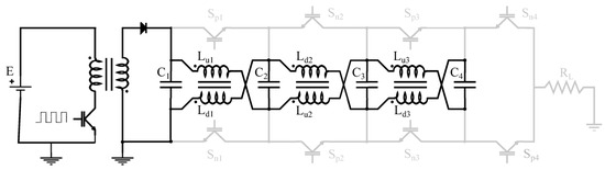
Figure 4.
Charging phase.
It should be mentioned that the first charging of the capacitors starts from fully discharged state. However, after the first discharge, the capacitors are not fully discharged. So, the recharge of the capacitors will take a shorter time as compared to the first one.
The capacitors’ initial state of charge depends on the last pulse width and the load’s impedance, and the recharging time depends on the fly-back DC–DC converter power. These two parameters are the main limitations of the generator’s maximal repetition rate.
3.2. The Second Phase—Standby
When the voltage across capacitors reaches its final value, the fly-back converter stops switching and the generator enters a standby state.
During this phase, all switches are off, the capacitors are charged, and the system waits for the triggering signal.
3.3. The Third Phase—Serial Discharge of the Capacitors
During the discharging phase, groups of switches or are closed depending on the chosen polarity (positive or negative, respectively, as shown in Figure 5). In this case, the two coils block the capacitors’ voltage and force them to discharge in the load.
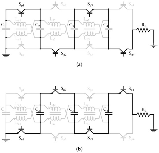
Figure 5.
Discharging path: (a) Positive polarity; (b) negative polarity.
Due to the use of IGBTs/MOSFETs, it is possible to cut the pulse at any time after firing the generator to obtain a quasi-rectangular pulse with an adjustable pulse width. This means that in this case the discharge of the capacitors is just partial, and the time needed to charge them again is reduced. This can considerably increase the repetition rate of the generator.
It worth mentioning that in reality the pulse width is limited. It cannot be longer than or shorter than . The maximal value depends on the total capacitance of the generator and the load impedance, as given in Equation (1), as the equivalent circuit of the generator in the discharge phase is an RC circuit.
On the other hand is fixed by the rising and falling times of the generated pulses which depend on several parameters: the dynamic of the chosen switches, the gate driving circuit, and also the total inductance of path followed by the current.
To evaluate the potential of the proposed structure, a comparative analysis with two other structures from the literature [35,36] was conducted in terms of the number of components used and the level of controllability, as shown in Table 1.

Table 1.
Comparison between the proposed structure and others from literature.
For the same number of stages N, compared to the two structures from the literature, the proposed one requires less semiconductor switches: half the number of MOSFETs/IGBTs and just one diode. It also requires half the number of capacitors and an additional N pair of coupled inductors.
4. Simulation
In order to better understand the behaviour of the generator in different conditions and adjust the components, a SPICE model was developed and solved using the following final parameters:
- number of stages: 4;
- capacitance per stage: 170 nF;
- inductances: 5 mH;
- coupling factor: ;
- load resistance: .
The obtained results, shown in next figures, represent the different circuit parameters, such as the capacitors’ voltages, the inductors’ currents, and output pulses for different configuration.
Figure 6 shows the variation of the capacitors’ voltages and the inductors currents on the right. From the voltages waveforms, we can notice that the capacitors are charged almost simultaneously. The observed ripples are caused by the resonance between the capacitors and the different leakage inductances.
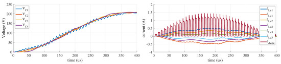
Figure 6.
Charging currents and voltages.
The currents through the each inductor are shown on the right. The symmetry of the waveforms proves that the same current flows through each pair of coils, but in opposite directions. The amplitudes of these currents decrease in successive sections as the number of capacitors remaining to be charged also decreases.
Figure 7 shows the obtained output pulses for different cases: for positive, negative, and bipolar pulses. Each case was simulated for different pulse widths to show its effect on the final pulse shape. One can see the voltage drop in the pulse amplitude caused by the discharge of the capacitors in the load which is proportional to the pulse width. From these results, it is clear that the generator can provide fully controllable pulses with a quasi-rectangular shape.
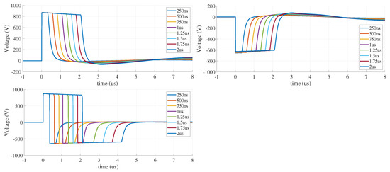
Figure 7.
Waveforms of the generated pulses obtained from simulation.
5. Experimental Validation
In order to validate the previous results, a three-stage generator was built and tested in the high-voltage laboratory at the Warsaw University of Technology, as shown in Figure 8.
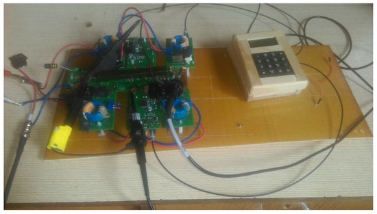
Figure 8.
Experimental setup of the prototype.
The generator uses 170 nF capacitors and 5 mH inductors. The chosen semiconductor switches are IXGF30N400 IGBT produced by IXYS which is a high-voltage IGBT designed for capacitor discharge. It can handle a voltage of 4 kV and a current of 30 A. Each switch has its own insulated power supply and gate-driving circuit designed to provide the best possible rising time. The whole system is controlled using an FPGA board: DE10-Lite based on Intel FPGA ship MAX10 referenced as 10M50DAF484C7G. The control signals are transmitted to the IGBT gate-driving circuits using optical links.
A typical sequence of bipolar pulses with repetition rate of 1000 pps is presented in Figure 9. Figure 10 shows details of a single positive pulse of the same sequence: quasi-rectangular shape with an amplitude of 7.5 kV, a pulse width of 2.5 μs, and a rise time of 28 ns.
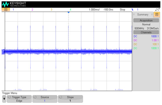
Figure 9.
A sequence of bipolar pulses.
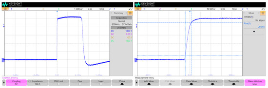
Figure 10.
A close look at the single positive pulse of the sequence presented in Figure 9.
Figure 11 shows two examples of customised bipolar pulses. The left inset shows two successive pulses of 1.5 μs width separated by 1.5 μs delay. On the right, three successive pulses are generated at one shot: two positives and one negative with the same widths and delays (1.5 μs). These two results demonstrate the great flexibility of the generator and the great possibility of controlling different pulse parameters. The device can be programmed to deliver a variety of different pulse patterns.
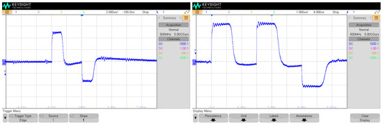
Figure 11.
Two example sequences of bipolar pulses (see the text for explanation).
6. Conclusions
In this paper, a new structure of SS-HVPG is proposed. It is designed to provide high flexibility and controllability over all characteristics of the generated pulses, which is a key point for biomedical applications to control the injected electric field dose.
The proposed structure is based on the Marx architecture, combining both versions for positive and negative polarisation and replacing classical spark gaps with solid-state MOSFETs/IGBTs. It uses coupled inductors for fast capacitor charging, providing high power efficiency.
The operation of the proposed circuit was validated using a SPICE simulation where the different key parameters were checked. These results were confirmed by a series of experimental tests made on an experimental prototype.
The presented generator provides full control over the generated pulses in terms of amplitude, pulse width, repetition rate, and polarity. It does not require a high-voltage supply due to its high-voltage gain, and it uses reduced number of switches compared to other generators with similar performances found in literature.
Author Contributions
Conceptualization, Y.A.; methodology, Y.A.; software, Y.A. and J.S.; validation, Y.A. and J.S.; formal analysis, Y.A. and J.S.; investigation, Y.A. and J.S.; resources, J.S.; data curation, Y.A. and J.S.; writing—original draft preparation, Y.A.; writing—review and editing, Y.A., J.S. and K.J.; visualization, Y.A., J.S. and K.J.; supervision, J.S.; project administration, J.S.; funding acquisition, J.S. All authors have read and agreed to the published version of the manuscript.
Funding
This research was partially founded by the CB POB grant of Warsaw University of Technology in frames of the project “High power and frequency electromagnetic impulse generator”, POB_182_42_Z01_POB7_2021.
Institutional Review Board Statement
Not applicable.
Informed Consent Statement
Not applicable.
Data Availability Statement
Not applicable.
Conflicts of Interest
The authors declare no conflict of interest.
Abbreviations
The following abbreviations are used in this manuscript:
| nsPEF | nanosecond pulsed electrical field |
| SS-HVPG | solid-state high-voltage pulse generator |
| MOSFET | metal oxide field-effect transistor |
| IGBT | insulated gate bipolar transistor |
| MS | magnetic switch |
References
- Carr, L.; Golzio, M.; Orlacchio, R.; Alberola, G.; Kolosnjaj-Tabi, J.; Leveque, P.; Arnaud-Cormos, D.; Rols, M.P. A nanosecond pulsed electric field (nsPEF) can affect membrane permeabilization and cellular viability in a 3D spheroids tumor model. Bioelectrochemistry 2021, 141, 107839. [Google Scholar] [CrossRef] [PubMed]
- Pakhomov, A.G.; Gudvangen, E.; Xiao, S.; Semenov, I. Interference targeting of bipolar nanosecond electric pulses for spatially focused electroporation, electrostimulation, and tissue ablation. Bioelectrochemistry 2021, 141, 107876. [Google Scholar] [CrossRef] [PubMed]
- Kasprzycka, W.; Trębińska-Stryjewska, A.; Lewandowski, R.B.; Stępińska, M.; Osuchowska, P.N.; Dobrzyńska, M.; Achour, Y.; Osuchowski, L.P.; Starzyński, J.; Mierczyk, Z.; et al. Nanosecond Pulsed Electric Field Only Transiently Affects the Cellular and Molecular Processes of Leydig Cells. Int. J. Mol. Sci. 2021, 22, 11236. [Google Scholar] [CrossRef] [PubMed]
- Lorenzo, M.F.; Bhonsle, S.P.; Arena, C.B.; Davalos, R.V. Rapid Impedance Spectroscopy for Monitoring Tissue Impedance, Temperature, and Treatment Outcome During Electroporation-Based Therapies. IEEE Trans. Biomed. Eng. 2021, 68, 1536–1546. [Google Scholar] [CrossRef]
- Sarathi, R.; Rayala, S.; Kumar, P.; Sundararajan, R. Effective pancreatic cancer treatment using electrical pulses: An in vitro model study. In Proceedings of the 2014 IEEE Conference on Electrical Insulation and Dielectric Phenomena (CEIDP), Des Moines, IA, USA, 19–22 October 2014; pp. 232–234. [Google Scholar] [CrossRef]
- Poompavai, S.; Sree, V.G.; Sridhar, T. Pulse Electric Field analysis on breast cancer model. In Proceedings of the 2015 International Conference on Condition Assessment Techniques in Electrical Systems (CATCON), Bangalore, India, 10–12 December 2015; pp. 168–172. [Google Scholar] [CrossRef]
- Sato, H.; Minamitani, Y.; Fujiwara, Y.; Ohnishi, N.; Katsuki, S. Development of High Power Burst Pulse Generator for Cancer Treatment and Investigation of Superiority of High Power Burst Pulse as against Single Pulse. In Proceedings of the 2018 IEEE International Power Modulator and High Voltage Conference (IPMHVC), Jackson, WY, USA, 3–7 June 2018; pp. 477–481. [Google Scholar] [CrossRef]
- Potočnik, T.; Miklavčič, D.; Maček Lebar, A. Gene transfer by electroporation with high frequency bipolar pulses in vitro. Bioelectrochemistry 2021, 140, 107803. [Google Scholar] [CrossRef]
- Kranjc, M.; Kranjc Brezar, S.; Serša, G.; Miklavčič, D. Contactless delivery of plasmid encoding EGFP in vivo by high-intensity pulsed electromagnetic field. Bioelectrochemistry 2021, 141, 107847. [Google Scholar] [CrossRef]
- Tu, S.H.L.; Tsai, P.Y. A Class-E high-voltage pulse generator for ultrasound medical imaging applications. Microelectron. J. 2020, 100, 104776. [Google Scholar] [CrossRef]
- Elgenedy, M.A.; Massoud, A.M.; Ahmed, S.; Williams, B.W. A High-Gain, High-Voltage Pulse Generator Using Sequentially Charged Modular Multilevel Converter Submodules, for Water Disinfection Applications. IEEE J. Emerg. Sel. Top. Power Electron. 2018, 6, 1394–1406. [Google Scholar] [CrossRef]
- Xiao, S.; Zhou, C.; Yang, E.; Rajulapati, S.R. Nanosecond bipolar pulse generators for bioelectrics. Bioelectrochemistry 2018, 123, 77–87. [Google Scholar] [CrossRef]
- Achour, Y.; Starzyński, J.; Łasica, A. New Marx Generator Architecture with a Controllable Output Based on IGBTs. IEEE Trans. Plasma Sci. 2017, 45, 3271–3278. [Google Scholar] [CrossRef]
- Zhao, B.; Li, H.; Wang, L.; Liu, J.; Liu, X. A New Modular XRAM-Like Inductive High- Current Pulse Generator Circuit Topology. IEEE Access 2020, 8, 210158–210166. [Google Scholar] [CrossRef]
- Achour, Y.; Starzyński, J.; Rąbkowski, J. Modular Marx Generator Based on SiC-MOSFET Generating Adjustable Rectangular Pulses. Energies 2021, 14, 3492. [Google Scholar] [CrossRef]
- Rong, C.; Jianhua, Y.; Xinbing, C.; Baoliang, Q. Developing a solid-state quasi-square pulse Marx generator. Rev. Sci. Instruments 2018, 89, 064707. [Google Scholar] [CrossRef]
- Hochberg, M.; Sack, M.; Herzog, D.; Weisenburger, A.; An, W.; Fetzer, R.; Mueller, G. A Fast Modular Semiconductor-Based Marx Generator for Driving Dynamic Loads. IEEE Trans. Plasma Sci. 2019, 47, 627–634. [Google Scholar] [CrossRef]
- Achour, Y.; Starzyński, J.; Kasprzycka, W.; Trafny, E.A. Compact low-cost high-voltage pulse generator for biological applications. Int. J. Circuit Theory Appl. 2019, 47, 1948–1962. [Google Scholar] [CrossRef]
- Achour, Y.; Starzyński, J.; Łasica, A. Compact nanosecond pulse generator based on IGBT and spark gap cooperation. Bull. Pol. Acad. Sci. Tech. Sci. 2020, 68, 377–388. [Google Scholar]
- Zhang, H.; Shu, T.; Zhang, Z. An ultra-compact 260 MW PFN-Marx generator. In Proceedings of the 2020 IEEE International Conference on High Voltage Engineering and Application (ICHVE), Beijing, China, 6–10 September 2020; pp. 1–4. [Google Scholar] [CrossRef]
- Mi, Y.; Wan, J.; Bian, C.; Zhang, Y.; Yao, C.; Li, C. A high-repetition-rate bipolar nanosecond pulse generator for dielectric barrier discharge based on a magnetic pulse compression system. IEEE Trans. Plasma Sci. 2018, 46, 2582–2590. [Google Scholar] [CrossRef]
- Huiskamp, T. Nanosecond pulsed streamer discharges Part I: Generation, source-plasma interaction and energy-efficiency optimization. Plasma Sources Sci. Technol. 2020, 29, 023002. [Google Scholar] [CrossRef]
- Plotnikov, V.; Diaz, G. High-voltage pulsed plasma generation with frequency control for streamer initiation in liquid phase. Plasma Res. Express 2020, 2, 015003. [Google Scholar] [CrossRef]
- Ramezani, M.; Shayegani Akmal, A.A.; Niayesh, K. Solid-State High-Voltage Pulse Generator for Low Temperature Plasma Ion Mobility Spectrometry. IEEE Trans. Plasma Sci. 2019, 47, 1629–1636. [Google Scholar] [CrossRef]
- Meng, L.; Zeng, Y.; Zhu, D. Wire electrochemical micromachining of Ni-based metallic glass using bipolar nanosecond pulses. Int. J. Mach. Tools Manuf. 2019, 146, 103439. [Google Scholar] [CrossRef]
- Efremov, A.M.; Koshelev, V.I.; Plisko, V.V.; Sevostyanov, E.A. A high-power synthesized ultrawideband radiation source. Rev. Sci. Instruments 2017, 88, 094705. [Google Scholar] [CrossRef] [PubMed]
- Park, S.M.; Song, S.H.; Jo, H.B.; Jeong, W.C.; Jang, S.R.; Ryoo, H.J. Solid-State Pulsed Power Modulator for 9.3 GHz 1.7 MW X-Band Magnetron. IEEE Trans. Ind. Electron. 2021, 68, 1148–1154. [Google Scholar] [CrossRef]
- Achour, Y.; Starzyński, J.; Josko, A. Nanosecond EMP simulator using a new high voltage pulse generator. Prz. Elektrotech. 2017, 93, 33–36. [Google Scholar] [CrossRef][Green Version]
- Achour, Y.; Starzyński, J.; Josko, A.; Suproniuk, M. D-dot, Bdot Data Processing of Fields Generated with Broadband Pulsed Antenna. Prz. Elektrotech. 2019, 95, 109–112. [Google Scholar]
- Gholamalitabar, H.; Adabi, J.; Rezanejad, M. A Modular Step-Up High-Voltage Bipolar Pulse Generator. IEEE Trans. Plasma Sci. 2019, 47, 2736–2741. [Google Scholar] [CrossRef]
- He, Y.; You, X.; Ma, J.; Yu, L.; Zeng, W.; Dong, S.; Zhang, Z.; Yao, C. A Polarity-Adjustable Nanosecond Pulse Generator Suitable for High Impedance Load. IEEE Trans. Plasma Sci. 2020, 48, 3409–3417. [Google Scholar] [CrossRef]
- Deng, Z.; Ding, Z.; Yuan, Q.; Ding, W.; Ren, L.; Wang, Y. High voltage nanosecond pulse generator based on diode opening switch and magnetic switch. Rev. Sci. Instruments 2021, 92, 064713. [Google Scholar] [CrossRef]
- Watanabe, M.; Kamiya, J.; Takayanagi, T. Design and Circuit Simulation of a Magnetic Switching System for Kicker Magnet Power Supply of 3 GeV RCS in J-PARC. IEEE Trans. Appl. Supercond. 2010, 20, 1681–1684. [Google Scholar] [CrossRef]
- Kim, S.H.; Ehsani, M. Control and Analysis of Magnetic Switch Reset Current in Pulsed Power Systems. IEEE Trans. Power Electron. 2014, 29, 529–533. [Google Scholar] [CrossRef]
- Redondo, L.M.; Zahyka, M.; Kandratsyeu, A. Solid-State Generation of High-Frequency Burst of Bipolar Pulses for Medical Applications. IEEE Trans. Plasma Sci. 2019, 47, 4091–4095. [Google Scholar] [CrossRef]
- Liu, Y.; Fan, R.; Zhang, X.; Tu, Z.; Zhang, J. Bipolar high voltage pulse generator without H-bridge based on cascade of positive and negative Marx generators. IEEE Trans. Dielectr. Electr. Insul. 2019, 26, 476–483. [Google Scholar] [CrossRef]


Publisher’s Note: MDPI stays neutral with regard to jurisdictional claims in published maps and institutional affiliations. |
© 2022 by the authors. Licensee MDPI, Basel, Switzerland. This article is an open access article distributed under the terms and conditions of the Creative Commons Attribution (CC BY) license (https://creativecommons.org/licenses/by/4.0/).