1. Introduction
The urban transport system based on trams as the basic means of transport is one of the oldest systems of human transport in urban agglomerations. A tram is a more efficient, cheaper-to-operate, and greener means of transport compared to a bus [
1,
2].
Bearing in mind the directions of the EU transport policy considering such phenomena in cities and on its outskirts, such as congestion, air pollution, aging people in cities, and the need to provide people with disabilities with conditions to move, constructors and manufacturers of tram vehicles began to include contracting authorities’ requirements. Low floor, air-conditioning, and increased speed, while reducing noise and vibrations, have become the basic requirements set by public transport operators in cities.
Drive systems with independently rotating wheels are increasingly used in modern tram vehicles. In this type of bogie solution, the wheels mounted on a given wheelset can rotate at different speeds, causing unfavorable dynamic phenomena in the wheel–rail system. There are many publications on the dynamics of such a set, bearing in mind primarily the stability of traffic [
3,
4,
5,
6], and publications proposing to improve the dynamics of traffic in such a case. Some relate to the setting up some given elastic–dissipative characteristics of a wheels torsion joint in a wheelset. The using of sprung wheels mounted on a rigid axle is the simplest solution [
7,
8].
More advanced technical solutions include special devices for reducing the torsion-al rigidity of a wheelset axle. A number of them are focused on ensuring the optimal characteristics of the torsion coupling of the wheels in a wheelset. The use of a limited slip differential device [
9,
10] is an example of this approach. The research of recent decades proves that the concept of including an IRW is practically feasible by improving the wheel-to-bogie and bogie-to-body interaction characteristics using mechatronic systems with passive mechanisms for monitoring of a wheelsets position in the horizontal plane. The goal of this study was to achieve minimum lateral forces and low wear [
11,
12,
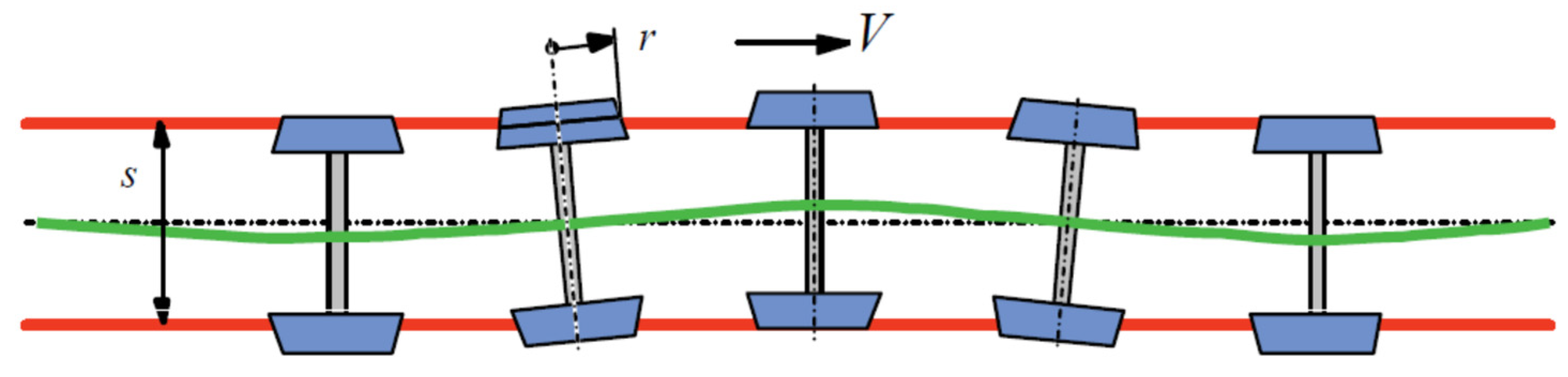
13]. The use of the control system enables the adjustment of the rotational speeds of individual wheels to the different radii of rails occurring on the curves of the tracks. However, the introduction of an innovative solution of tram bogies into common operation includes a few problems related to the dynamics of the motion of a rail vehicle, which include, among others, the lack of oscillating movement of the wheelsets when driving on a straight track (
Figure 1) and the resulting tendency for constant contact of the wheel flange with the rail [
14,
15]. These undesirable effects lead to excessive wear of the wheels and the rails, and, in extreme cases, may lead to vehicle derailment [
16,
17].
The currently conducted research concerns mainly the dynamics of the movement of a railway bogie, considering the side unevenness of the track or the properties resulting from the wheel profile [
18,
19,
20], but, unfortunately, without the electric drive system. The induction motor control strategy plays a key role in ensuring the stable movement of the wheelset in special conditions [
21], which include the movement along a transition curve connecting a straight track with a section of a curved track, or motion along a straight track, but with significant transverse track irregularities. Most often in such cases, scalar and vector methods are used to control the asynchronous motors, driving individual wheels of the bogie through integrated gears. In the case of scalar control, the most common method is the control method maintaining a constant voltage to frequency ratio (U/f = const.) to create a constant value of electromagnetic flux in an induction motor [
22].
The use of this type of control allows for continuous adjustment of the engine speed in a wide range, which can be successfully used to drive a tram vehicle. Moreover, by changing the voltages supplying induction motors based on the difference in rotational speeds of individual wheels, i.e., the left wheel and the right wheel, it is possible to significantly reduce the unfavorable phenomenon of wheel set snaking.
An unquestionable disadvantage of scalar methods for controlling asynchronous motors is the lack of control of the torque generated by the motor in transient states [
23]. In the case of vector control methods, it is possible to adjust the stator current components to obtain the appropriate position of the stator current vectors in relation to the rotor flux [
24]. Such a method of regulation ensures the maximization of the generated torque and the stabilization of parameters in the dynamic states of the drive’s operation. One of the most popular vector control methods, i.e., the method oriented towards direct control of the rotating magnetic field of the stator, can be used to control the driving torque of individual wheels during the movement of rail vehicles under various operating conditions [
25].
The problems of synchronization of the rotational speed of electric drives are widely analyzed in the case of other technological objects, e.g., in metallurgical issues. In [
26,
27,
28,
29] the authors analyzed a drive system of a section of a metallurgical rolling table and vibrations in the drive system of a paper machine. A significant problem in the rolling technologies used in the production of sheets, pipes or, for example, rails is the problem of synchronization of motors driving cylindrical mechanisms, considering vibrations, production accuracy, optimization of rolling time, and production costs. These issues were dealt with by the authors in [
30,
31,
32,
33]. The problems of synchronizing several electric drives have recently been taken up also in the field of broadly understood transport, in naval and aerospace applications. As an example of this trend, electromechanical drive alternatives are currently being considered as a replacement to pneumatic and/or hydraulic thrust reverse actuation systems in future aircraft [
34,
35,
36].
The innovation of the proposed solution consists in building a mathematical model of the electromechanical system, later used in the simulation model, and then used in the construction of a prototype of a low-floor tram vehicle. In the construction of the mathematical model of the rail vehicle, the Boltzmann–Hamel equations [
2] were used, enabling the modeling of nonholonomic constraints resulting from the specificity of nonlinear phenomena occurring in the wheel–rail contact system. On the other hand, the adopted model of the drive control system was taken from the literature rich in this area. The combination of these two models and the use of the developed method using the actual angular velocity values of the wheels of the wheelsets in the control system in the prototype of the low-floor tram vehicle should be considered an innovation. A prototype of such a tram was then put into production.
The introduction contains a justification for taking up the topic and a review of the literature on the topic. Then, the constructional solutions used for the boogie are discussed, in the case of low-floor trams, considering the foundation of the drive and transmission of the driving torque to the wheels of the vehicle. The next part of the work presents the concept of the wheel control system of a low-floor tram boogie and a simulation model of the electromechanical system of the vehicle–drive system–control system. Then, the results of the control system simulation are presented and discussed. The work is completed with conclusions.
2. Design Solutions of the Drive System Depending on the % of Low Floor
The percentage of low floor occupancy in a tram vehicle may vary and depends on, inter alia, the requirements formulated by the contracting authority or the condition of the track infrastructure on which the tram vehicle is to be operated [
37,
38].
Among the low-floor trams, there are vehicles that use a conventional power bogie and conventional towed bogie. They cover 9 to 15% of the low floor area but can also cover up to 48% of the low floor area. The next category of low-floor trams are vehicles that use conventional powered bogies at each end and innovative towed bogies. Certain structures fitted with towed bogies of a conventional design, but with smaller diameter wheels, should fall into this category. They have 50 to 75% of the low-floor, uninterrupted space between the bogies. The “highest” category of design advanced uses vehicles’ innovative propulsion and trailed bogies. They have approx. 100%, low-floor, uninterrupted surfaces.
The adoption of an appropriate low-floor solution at the stage of formulating design assumptions also implies later solutions for the vehicle’s chassis. The basic subassemblies of the running gear of a tram vehicle are a wheelset structurally connected to the bogie frame through the components of a compliant system of the first degree.
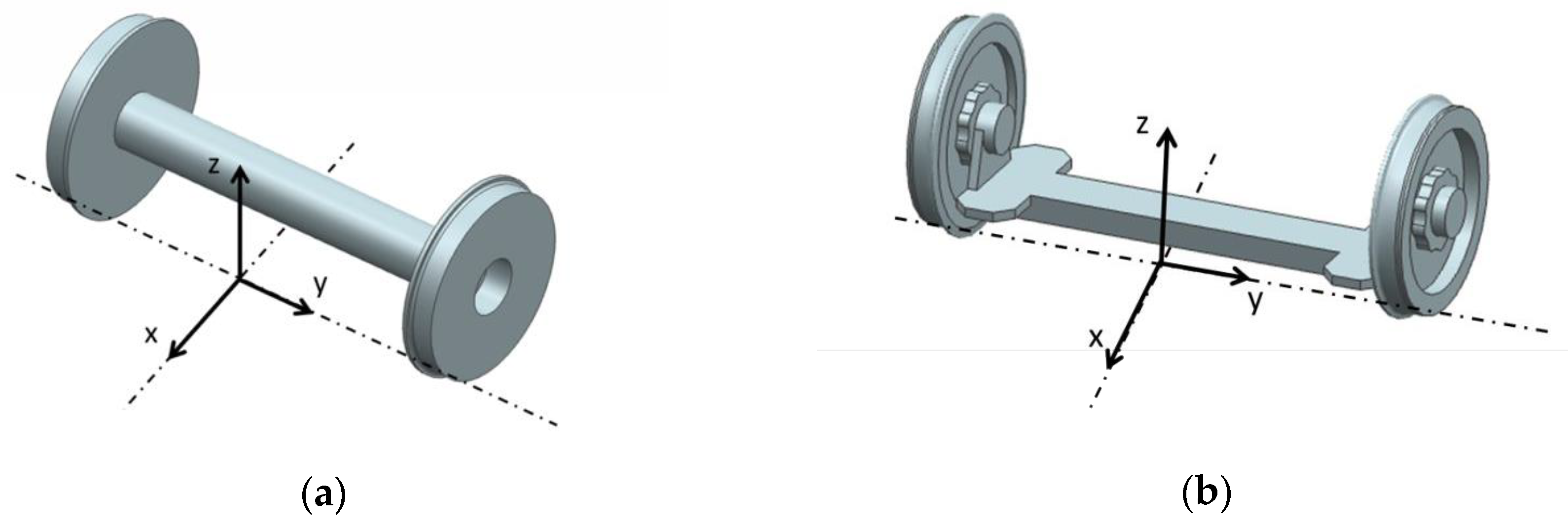
Depending on whether the bogie is to act as a driving or trailed trolley, its structure is more or less complex. The design of 100% low-floor vehicles excludes the use of classic wheelsets with fixed axles between the right and left wheels. A classic and unconventional wheelset is shown in
Figure 2a,b.
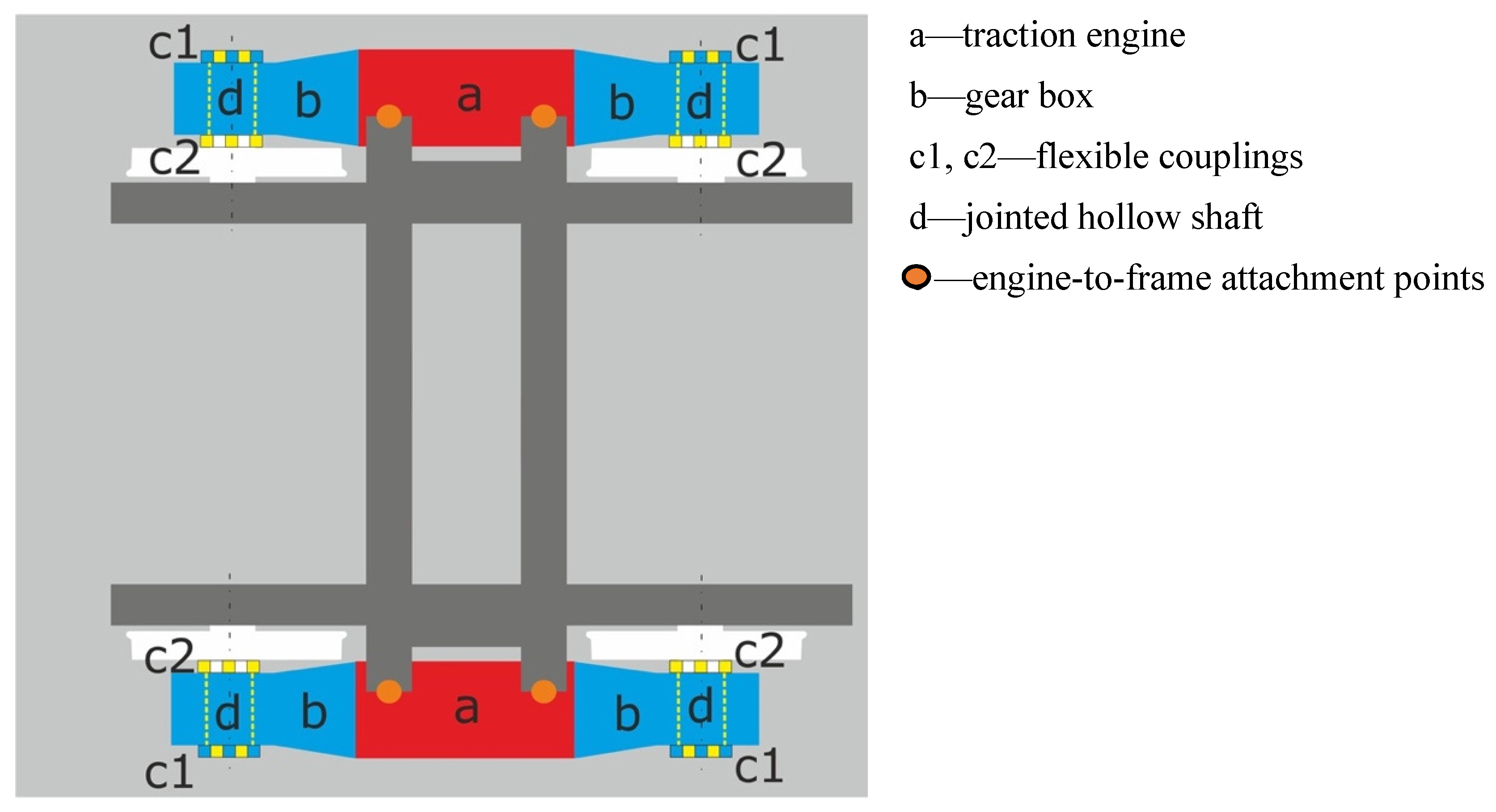
It is generally assumed that in low-floor trams the floor is approx. 350 mm above the rail head, and its upper part cannot be placed higher than approx. 600 mm above the rail head. In a fully low-floor tram, the entire floor is at the same level, approx. 350 mm above the rail head. However, above the bogies, the floor may be slightly higher (up to 450 mm above the top rail). The adoption of one of the two wheelsets, classic or unconventional, in the design of the bogies, forced by the adopted assumption regarding the percentage of coverage of the body with a low floor, results in the adopted solution for the drive system. In the case of a bogie with conventional wheel sets, the basic solution of the drive unit in the bogie is the drive carried out by one motor driving two axles or two identical motors driving each axle separately (
Figure 3 and
Figure 4). In such a case, each axle of the wheelset in the bogie is driven by a torque of the same value and each wheel of the wheelset has the same rotational speed.
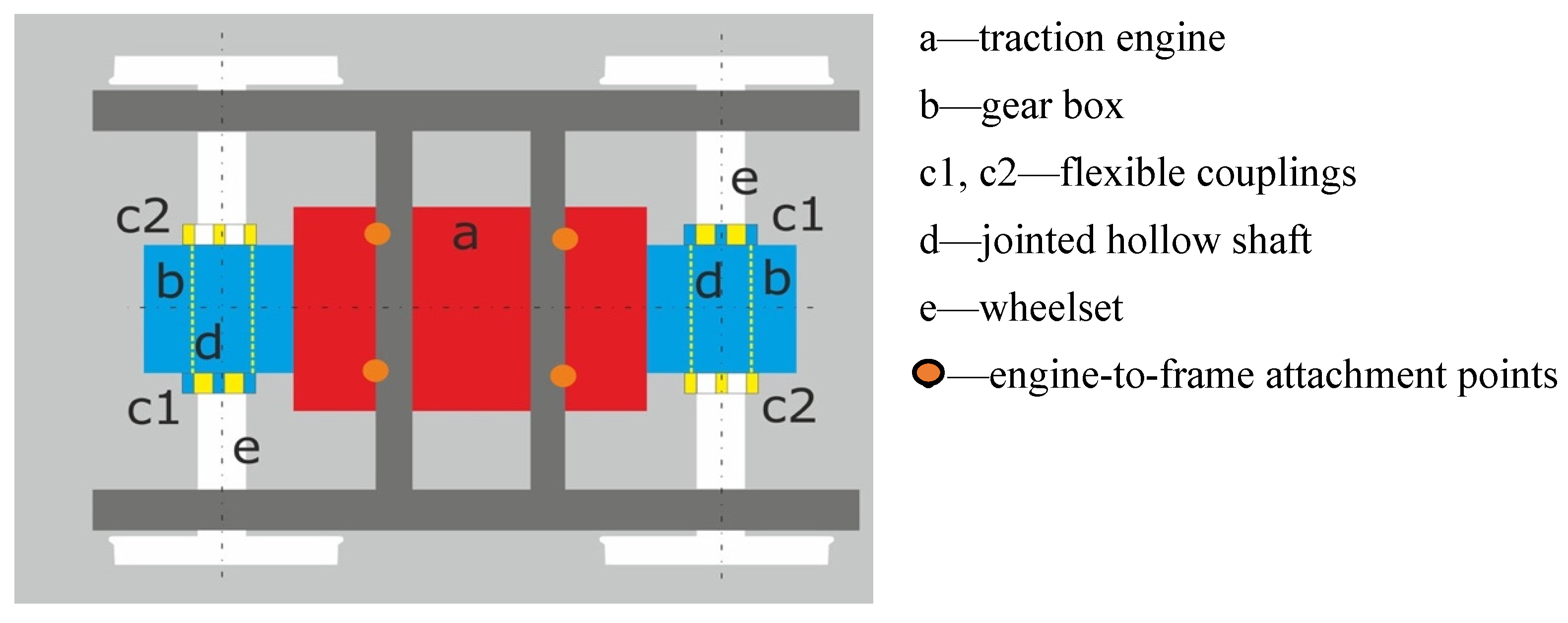
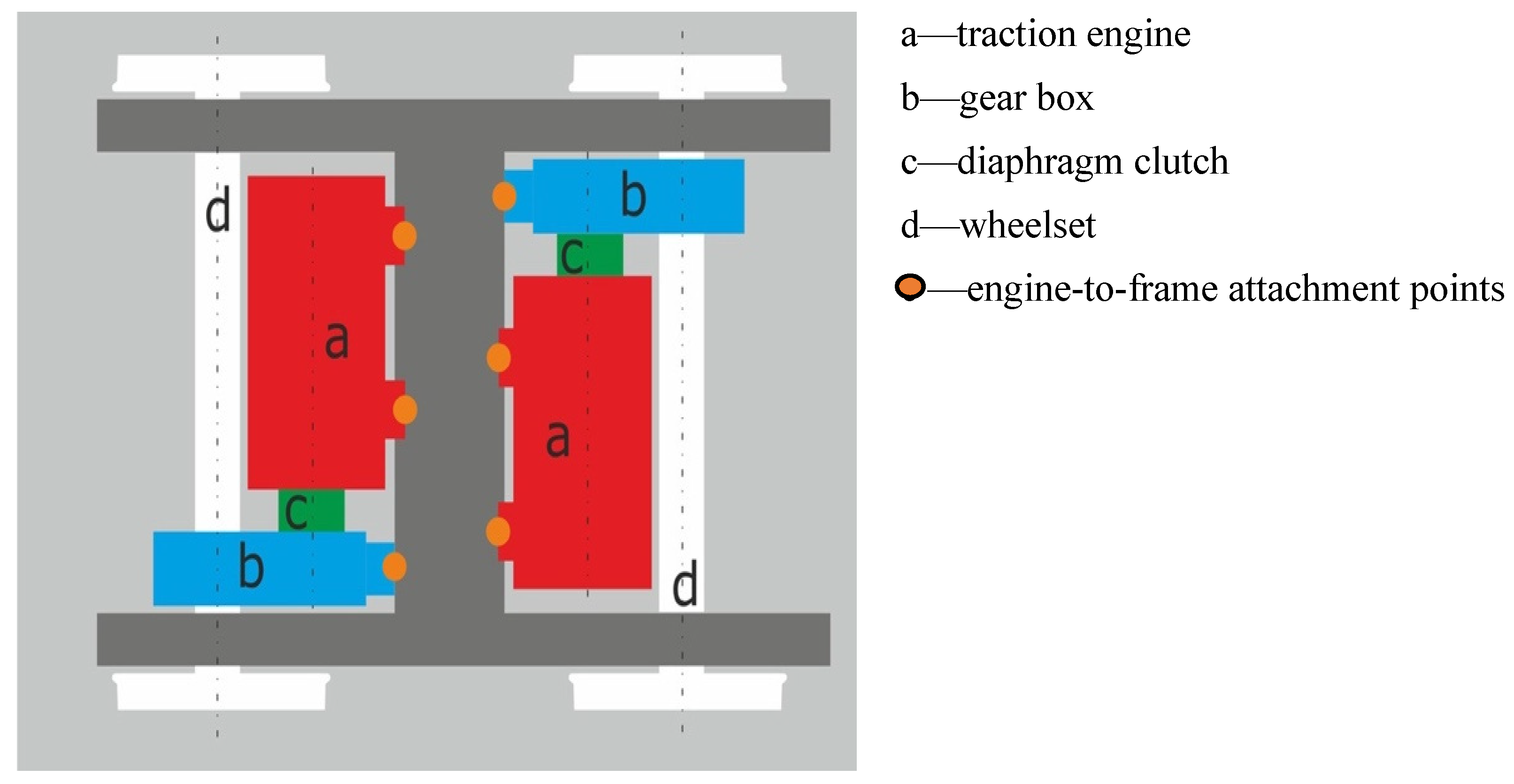
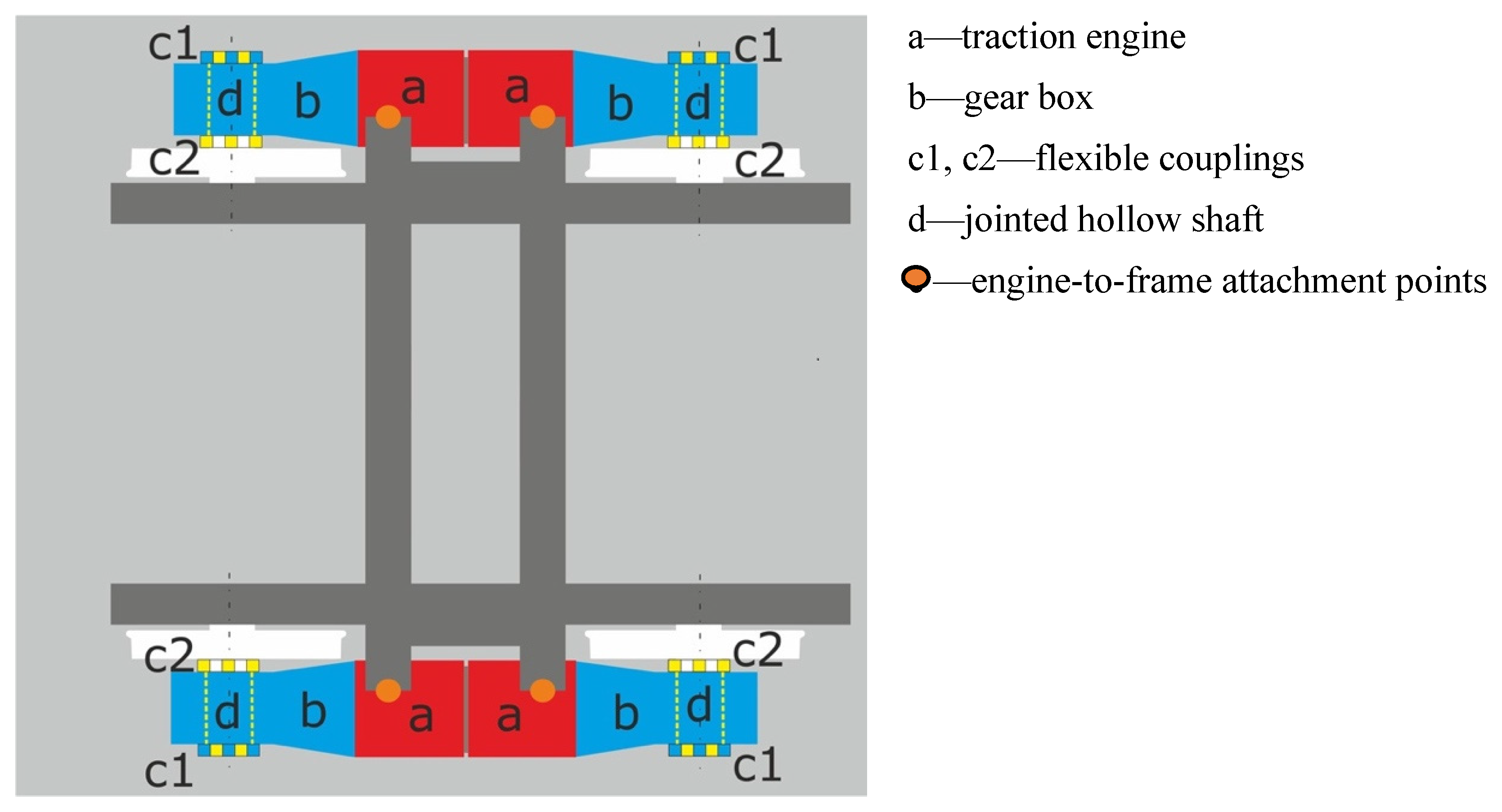
However, in the case of wheelsets with independently rotating wheels, a drive with the use of two motors is used, while one traction motor drives two wheels (
Figure 5) or a drive with the use of four motors (
Figure 6). In such a case, each wheel has an individual drive, which provides appropriate conditions for controlling independently rotating wheels and, thus, improves the dynamic behavior of the bogie in the track and significantly reduces the wear of wheel profiles and rails.
In the presented work, the analyzed system will be the one shown in
Figure 6.
4. Simulation Model Setup
4.1. Model of the Mechanical System of the Vehicle
There is a rich literature on modelling a rail vehicle, which dates back to the 19th century. The 20th and 21st centuries have seen a dynamic development of rail transport, high-speed railways, and methods of testing rail vehicles [
15,
39,
40].
The general form of the mathematical model of the rail vehicle adopted in the tests can be written as (6) and (7):
where:
M, C, K—matrices of inertia, damping and elasticity,
q—vector of generalized coordinates,
p—vector of forcing forces:
f(t)—vector of exciting forces, which also includes the forces coming from the drive and control, and
h(q,)—vector of forces occurring in the wheel–rail contact system.
The number of degrees of freedom of the system described by the matrix Equation (6) may be from several to several dozen, depending on the structure of the vehicle and the structure of its model.
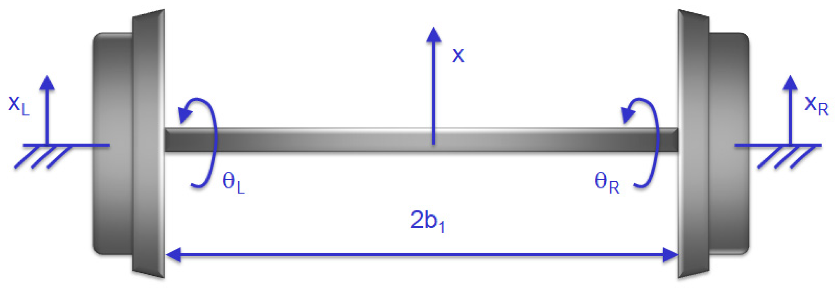
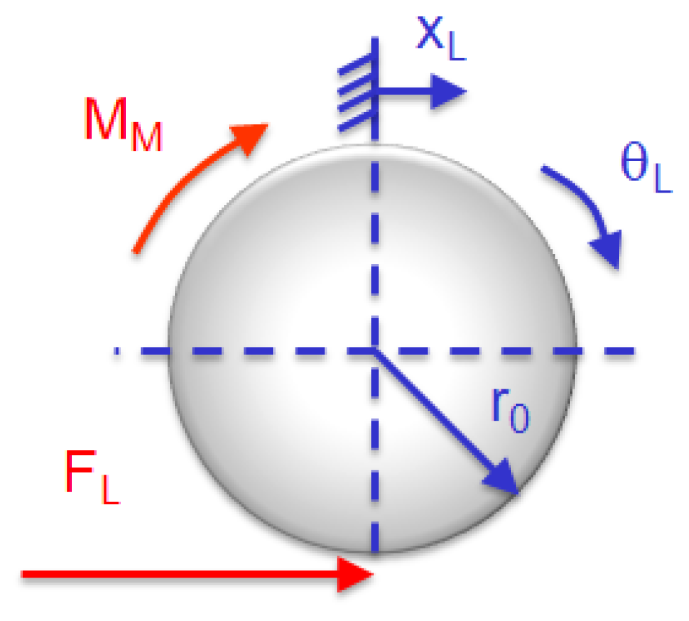
In the case of a single wheelset with independently rotating wheels, the system model has four degrees of freedom, i.e., y1 lateral displacement of the center of mass of the set, the tire relaxation angle ψ1, and the winding angles of the left and right wheels related to the angular velocities of the left wheel ωL and right ωR. On the other hand, the bogie model, in this case, consists of seven rigid bodies, i.e., the bogie frame, two sets and four independently rotating wheels. In total, the system has 14 degrees of freedom. In the linear model presented by Equation (8), the real profile of the contacting surfaces of the wheel and rail was considered by the equivalent conicity of the wheels, and the contact phenomenon of the rim with the rail in the form of a high elastic force acting after exceeding the value of the lateral displacement of 4.5 mm.
The equations of motion of a single wheelset for a linear model are presented below.
where:
mw,
Iwz,
Iw,
W,
a, and
r0—mass-inertia and geometrical parameters, characterizing the wheelset,
Kpy,
Cpy,
Kpx, and
Cpx—parameters of elastic-damping elements of the bogie,
f11,
f12,
f33,
f22, and
λ—parameters characterizing micro-slips in the area of contact between the wheel and rail.
If the phenomenon of nonlinear wheel–rail contact is taken into account in Equation (8), the functions describing the nonlinear wheel and rail profiles as well as the modified form of the functions defining micro-slips should be taken into account [
2]. However, if the control is considered, the Equations (3)–(5) should be added to the system of Equation (8). The obtained system of equations will describe the electro-mechanical model of a tram vehicle with independently rotating wheels.
4.2. Model of the Induction Motor—Control System
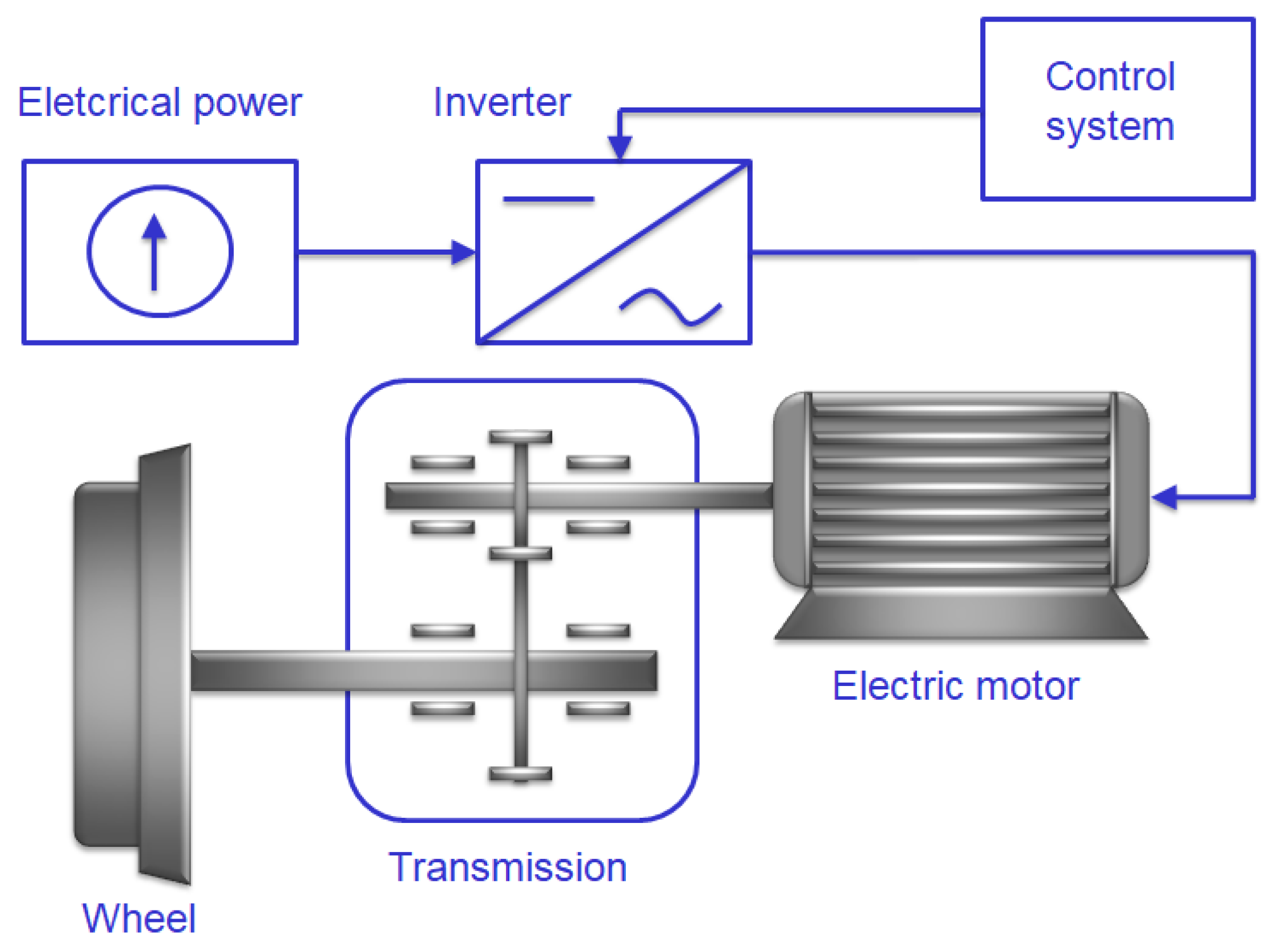
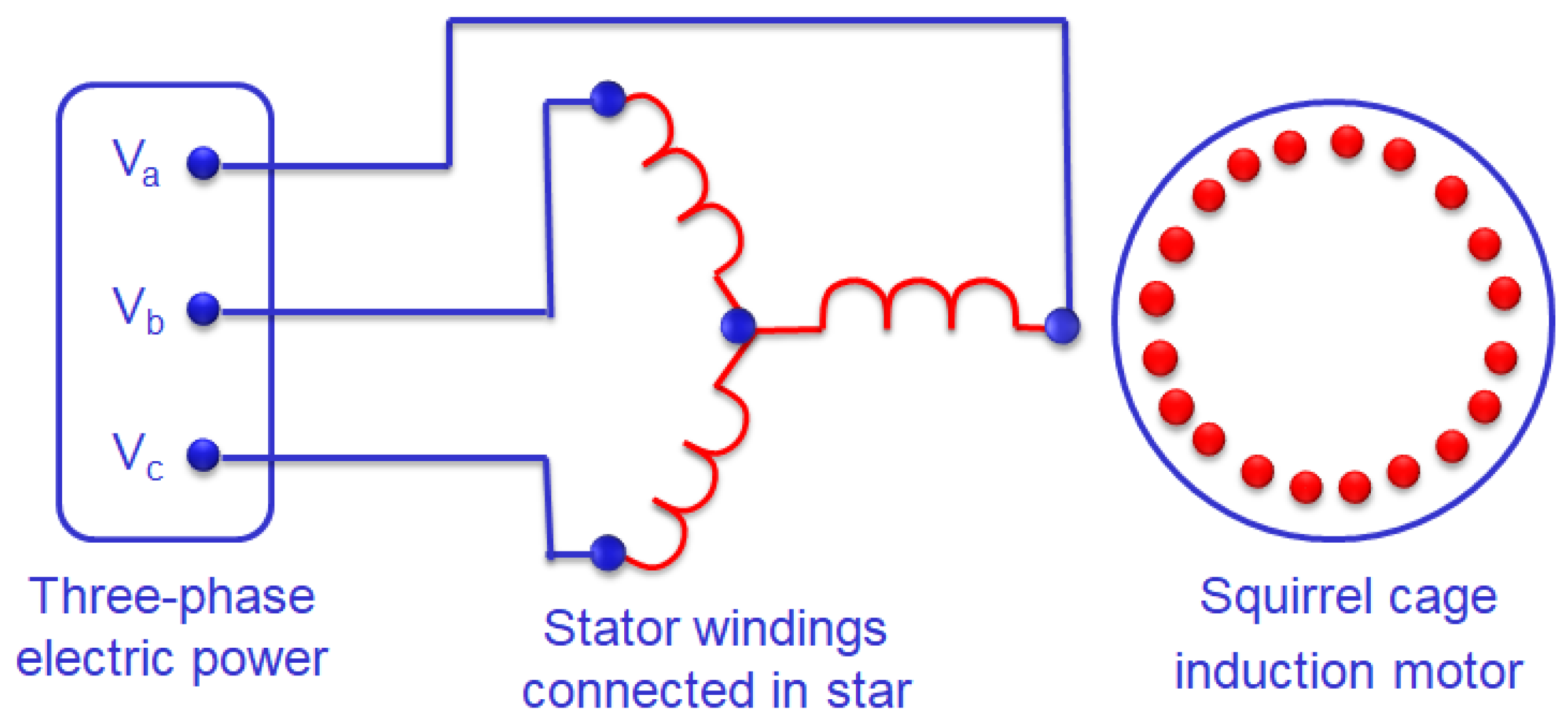
The basic element of the drive system is an induction motor belonging to the group of asynchronous machines, i.e., machines in which the rotor speed is different from the rotational speed of the stator electromagnetic field. The stator windings connected with a star are supplied from a three-phase network, which creates a rotating magnetic field which causes the motor’s squirrel cage rotor to rotate (
Figure 10).
Dependencies describing the variable voltage in individual power supply circuits of the motor are given as follows:
where its rated value considers the voltage drop caused by the resistance of the power cables [
25]:
where:
E—supply voltage,
Rc—cable resistance, and
is—value of the current consumed by the motor from the supply network.
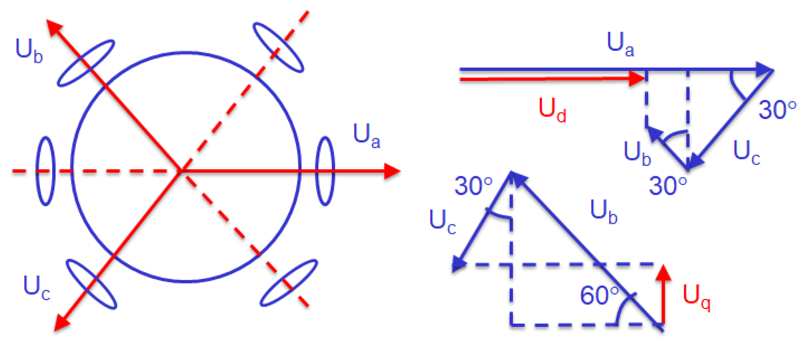
As a result of the Clarke transformation [
10], the voltage in the three-phase stator coordinate system is transformed to a two-phase coordinate system as follows:
where:
Ud and
Uq—vector components of the stator voltage. The application of the Clarke transform to the voltage transformation is illustrated in
Figure 11.
The equations determining the actual values of the currents flowing in the stator and rotor windings are written in the following form [
11]:
where:
ids and
iqs—vector components of the stator current,
idr and
iqr—vector components of the rotor current,
Ls—stator inductance,
Lr—rotor inductance,
Lm—mutual inductance,
Rs—stator resistance,
Rr—rotor resistance,
P—number of pole pairs,
—gear ratio, and
—rotation angle of the rotor.
4.3. Vector Control of an Induction Motor
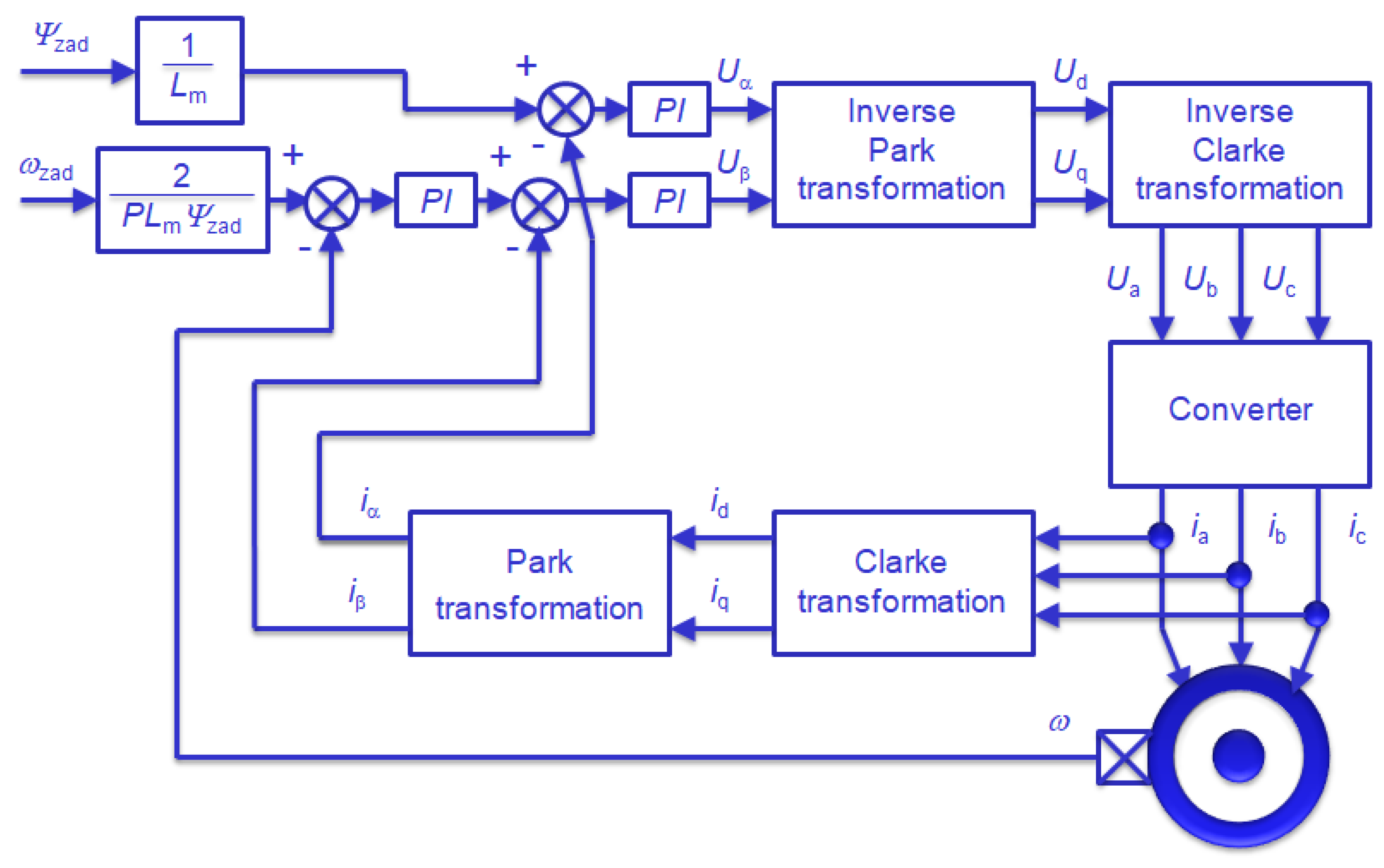
In the case of the selected vector control method (Field Oriented Control), it is possible to adjust the stator current components in order to obtain the appropriate position of the stator current vectors in relation to the rotor flux. Such a method of motor control ensures the maximization of the generated torque and the stabilization of system parameters in the dynamic states. One of the most popular vector control methods is the direct control of the rotating magnetic field (
Figure 12). By using the transformation of the stator winding currents (Clarke and Park transformation) to DC values, the Proportional–Integral (PI) control algorithms can be implemented easily, one for the outer speed control loop
ω and two for the inner current loops
iα and
iβ. The two PI controllers within the inner loops determine the voltage demands
Uα and
Uβ that, in turn, are converted back into the three-phase system via an inverse Park and Clarke transformation. Such transformed voltage demands
Ua, Ub, and
Uc are applied to the motor in order to facilitate appropriate current flow through the stator windings.
Relatively simple implementation makes the PI controller most widely used for the Field Oriented Control due to its simplicity, functional structure, and robust performance [
23] The main feature of the applied speed control loop
ω is the capability to use the proportional P and integral I in terms that influence the system dynamics in different ways. The first term P is used to generally eliminate an error between the set-point and the actual rotational speed of a wheel. Then the second term I is employed to remove the residual error by adding the previous cumulative value of the error. Such a control strategy in-creases the required accuracy of speed control.
In order to develop such a control system (
Figure 12), initially the currents measured in the three-phase stator system
ia,
ib, and
ic are transformed into a two-phase system,
ids,
iqs, using the Clarke transformation [
41]. On the other hand, the Park transformation introduces a rotating coordinate system as a reference, transforming the rotating stator current vector into simple variables that depend only on time.
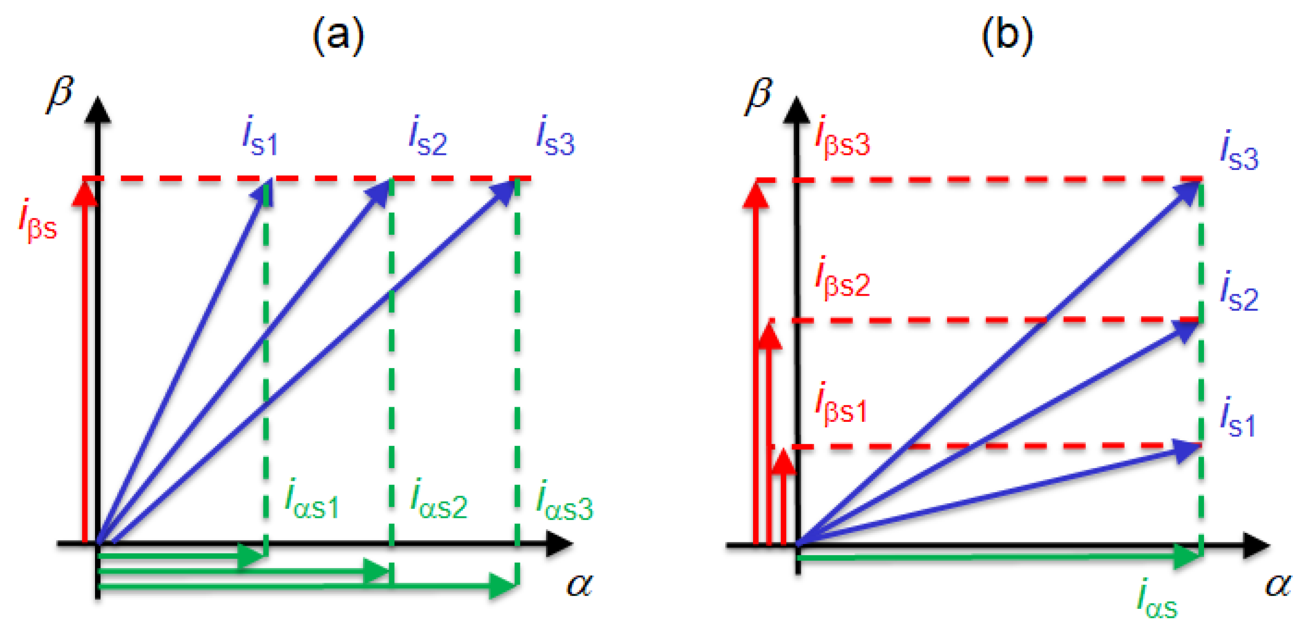
The effect of applying the Clarke and Park transformation in the vector control algorithm are two DC components:
- (a)
the vector component
corresponds to a change in the magnetizing flux (
Figure 13a) and
- (b)
the vector component
corresponds to a change in the motor torque (
Figure 13b).
Therefore, the motor control system includes two separate control systems, i.e., the stator magnetic flux control system (stator current component
iαs) and the motor electromagnetic torque control system (stator current component
iβs). The reference value for the upper control system (
Figure 12) is kept constant in order to obtain a constant value of the magnetic flux. The lower control system (
Figure 12) has two feedback loops in a cascade system, creating a speed and torque control system.
Subsequently, the inverse Park and Clarke transformations are used to transform the voltages determined in the rotating coordinate system into the three-phase system. The inverse Park transformation allows for converting the stator voltage vector defined in the rotating coordinate system into a stationary system [
41].
5. Simulation Results of the Truck Control System
For the purpose of this paper, the dynamic behavior of the rail vehicle together with its electric drive system is investigated in the MATLAB-Simulink
® software package. The equations of motion are programmed using the interactive graphical environment which allows the simulating and testing of a variety of time-varying systems [
Appendix A]. The proposed vector control method is used to control the rotational speeds of individual wheels while the bogie is driving along the curve of the track (
Figure 14).
There are many publications in the literature on the issue of radial alignment of a rail vehicle bogie with conventional wheelsets during the vehicle’s ride on a curve [
3,
4,
5]. These works are concerned about the conditions that should be met by the flexible system of the first and second levels of wheelset springing so that the wheel sets and the bogie can be positioned radially on the curve of the track. There are some proposals for reducing the impact of the vehicle on the track and, thus, reducing the wear of wheel and rail profiles.
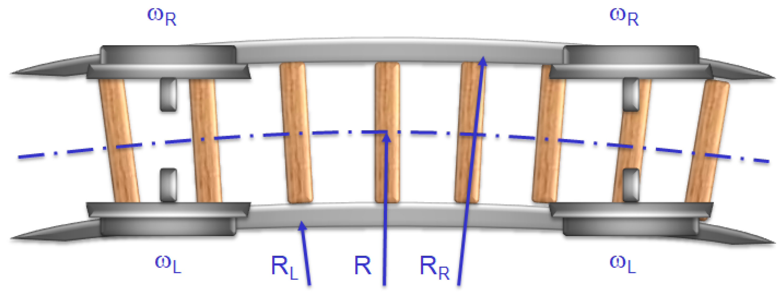
In the case of a bogie traveling in a curve with independently rotating wheels, the relationships describing the rotational speeds of the wheels on both sides of the bogie (
Figure 14) should be determined, which are as follows:
where:
—set value of the wheel rotational speed, and
—difference in wheel rotational speed resulting from different rail radii on the track curve.
Summing up both equations, a kinematic relationship is obtained that determines the relationship between the rotational speeds of the wheels in the following form [
6,
25].
from which the required speeds of the left and right wheels are determined:
Although the set speed
may have many values, its actual value is selected by the driver (Equation (14)). The rotational speed of specific wheels is automatically adjusted to a specific radius of the left and right rail profiles based on difference in wheel rotational speed
(Equation (13)). The proposed concept of the control system, written in Equations (13)–(15), was the basis for the developed control system, which was patented by patent [
42]. This patent was used by the Polish manufacturer and deployed in a tram which is currently used by public transport in Warsaw.
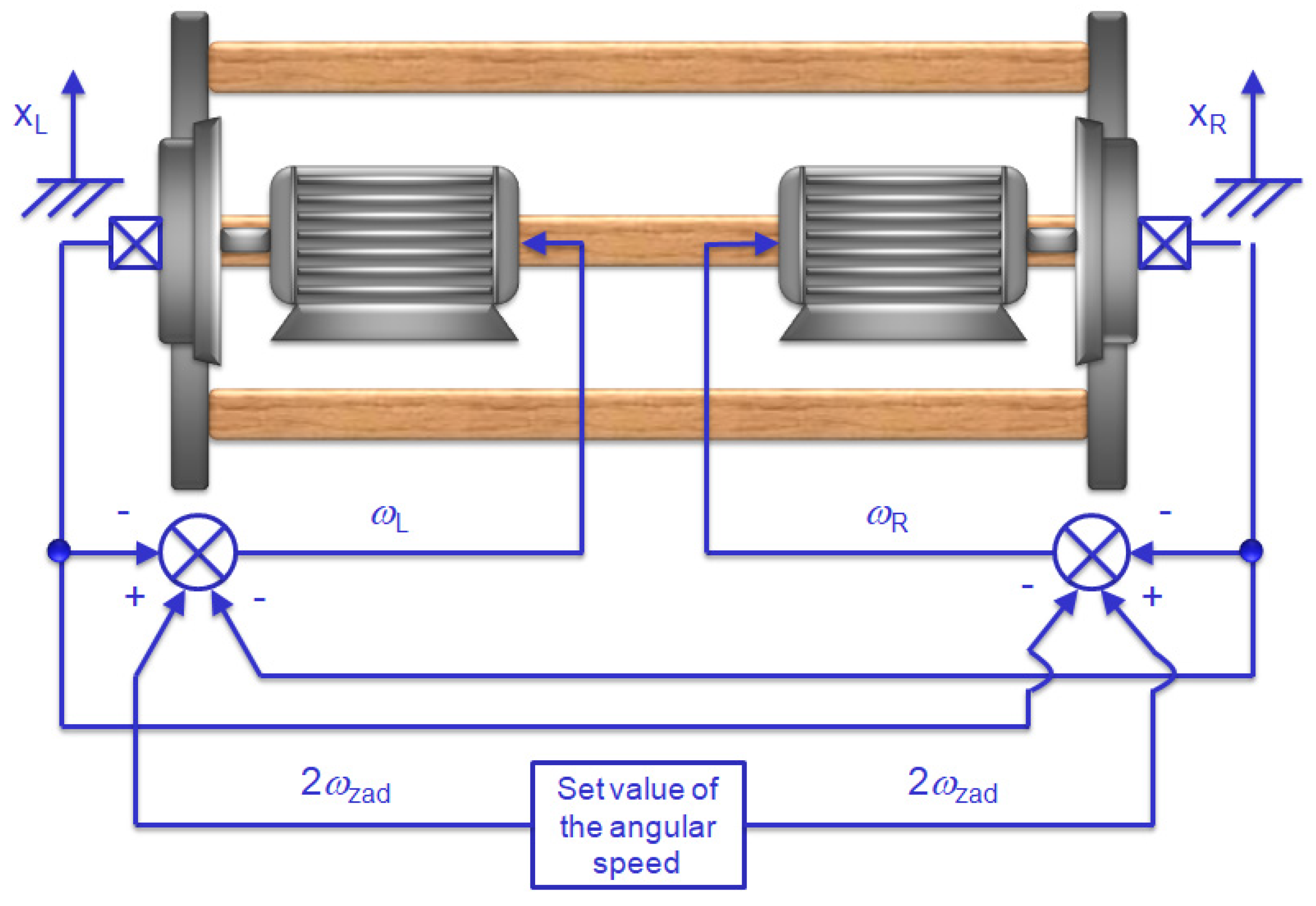
The above-described strategy of controlling the speed of individual wheels is used in the wheelset control system, and the corresponding block diagram is shown in
Figure 15:
As shown in
Figure 15, the doubled value of the rotational speed of the wheelset
is compared with the actual rotational speeds of individual wheels, i.e., the left wheel
and the right wheel
. By using such a control policy, it is possible to adjust the rotational speeds of individual wheels to different track radii occurring on the railway.
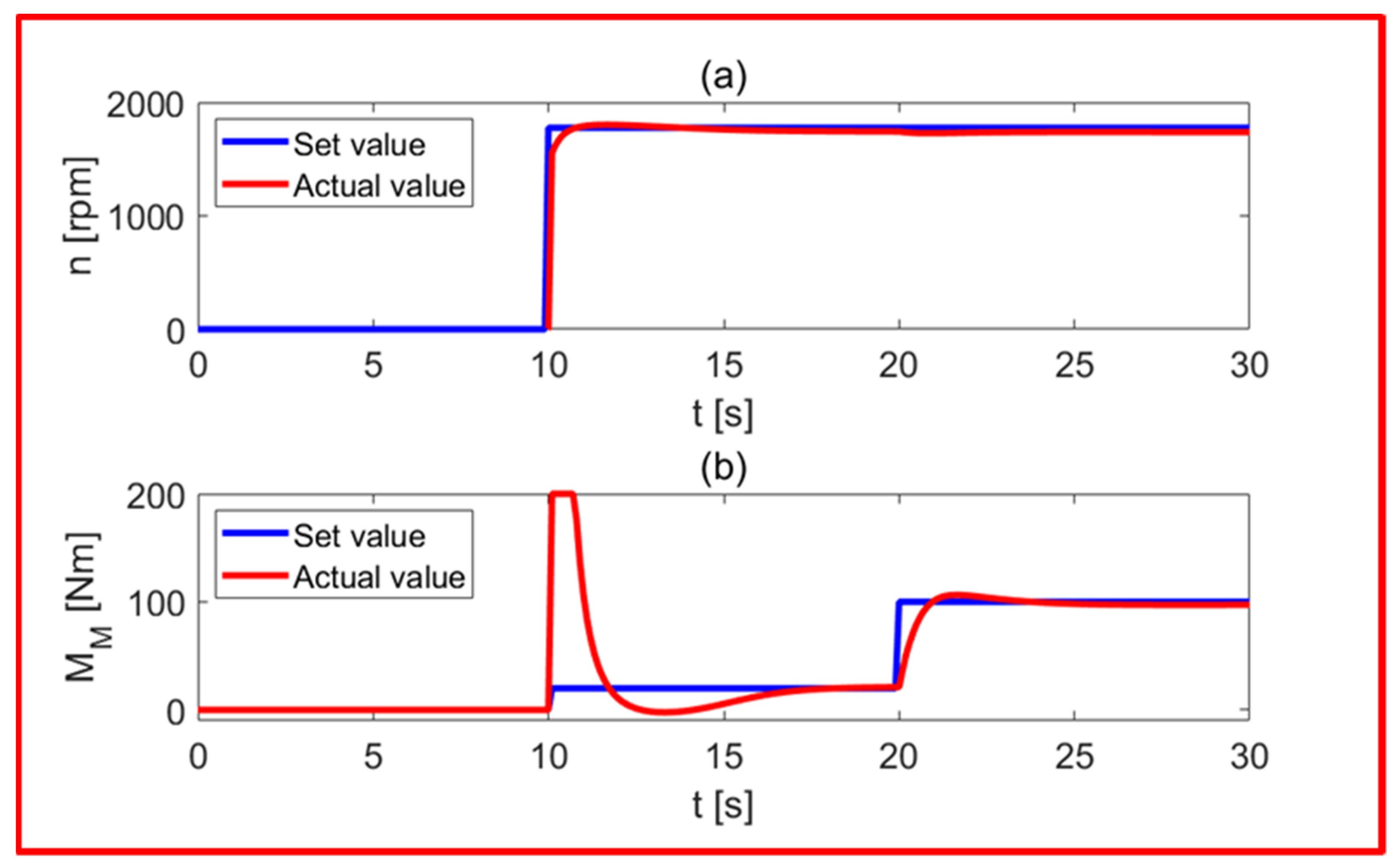
Figure 16 shows the rotational speed (
Figure 16a) and the electromagnetic torque of the motor (
Figure 16b), using the Field Oriented Control (FOC) method. As shown in the upper
Figure 16a, after 10 s of simulation time, the set value of the rotational speed changes to the value of 1800 rpm, and the rotor speeds up to this value after about 5 s of operation. Such a fast response of the motor is possible only at low load conditions (approx. 10 Nm), as shown in
Figure 16b. An instantaneous change in the set value of the rotational speed results in a slight oscillatory behavior because of PI controllers are used by the proposed control structure (see
Figure 12). After a simulation time of 20 s, a load torque of 100 Nm is applied, which is successfully counteracted by the electromagnetic torque of the motor after another 2 s of operation.
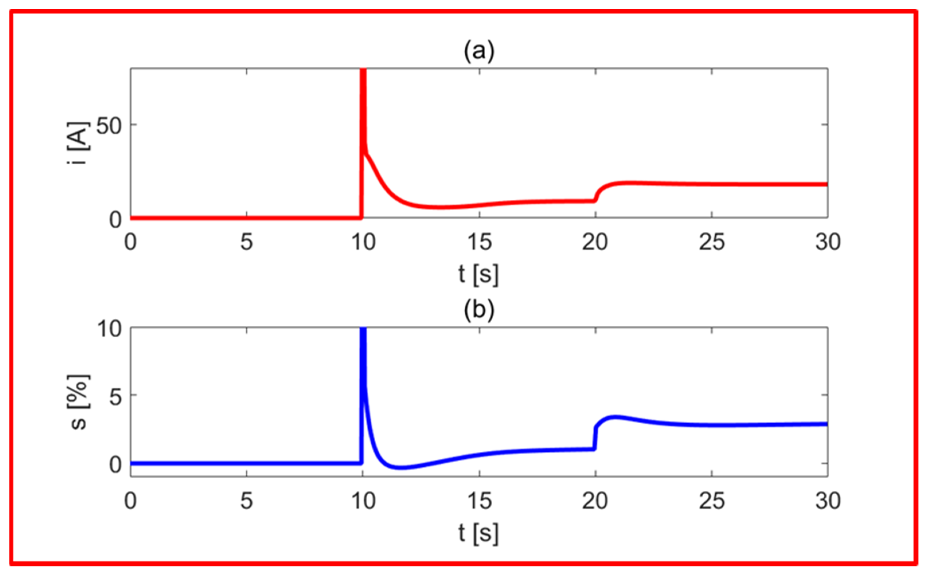
Figure 17 shows the current consumed from the power network (
Figure 17a) and the obtained rotor slip (
Figure 17b) during the operation of the asynchronous motor in accordance with the conditions specified in the previous figure. As it follows from the results presented in
Figure 17a, the start-up of an asynchronous motor is accompanied by a significant current consumption from the supply network (after 10 s of operation), which decreases in the further phase of steady operation. After 20 s, the intensity of the current consumed from the power network increases to the value of about 20 A, which is related to the motor load due to resistance to motion. In
Figure 17b, a significant engine slip is observed (in the 10th second of operation), which decreases when the motor is running at low load conditions, i.e., around synchronous speed. The motor slip increases during operation under load (after 20 s) and in this case amounts to several per cent.
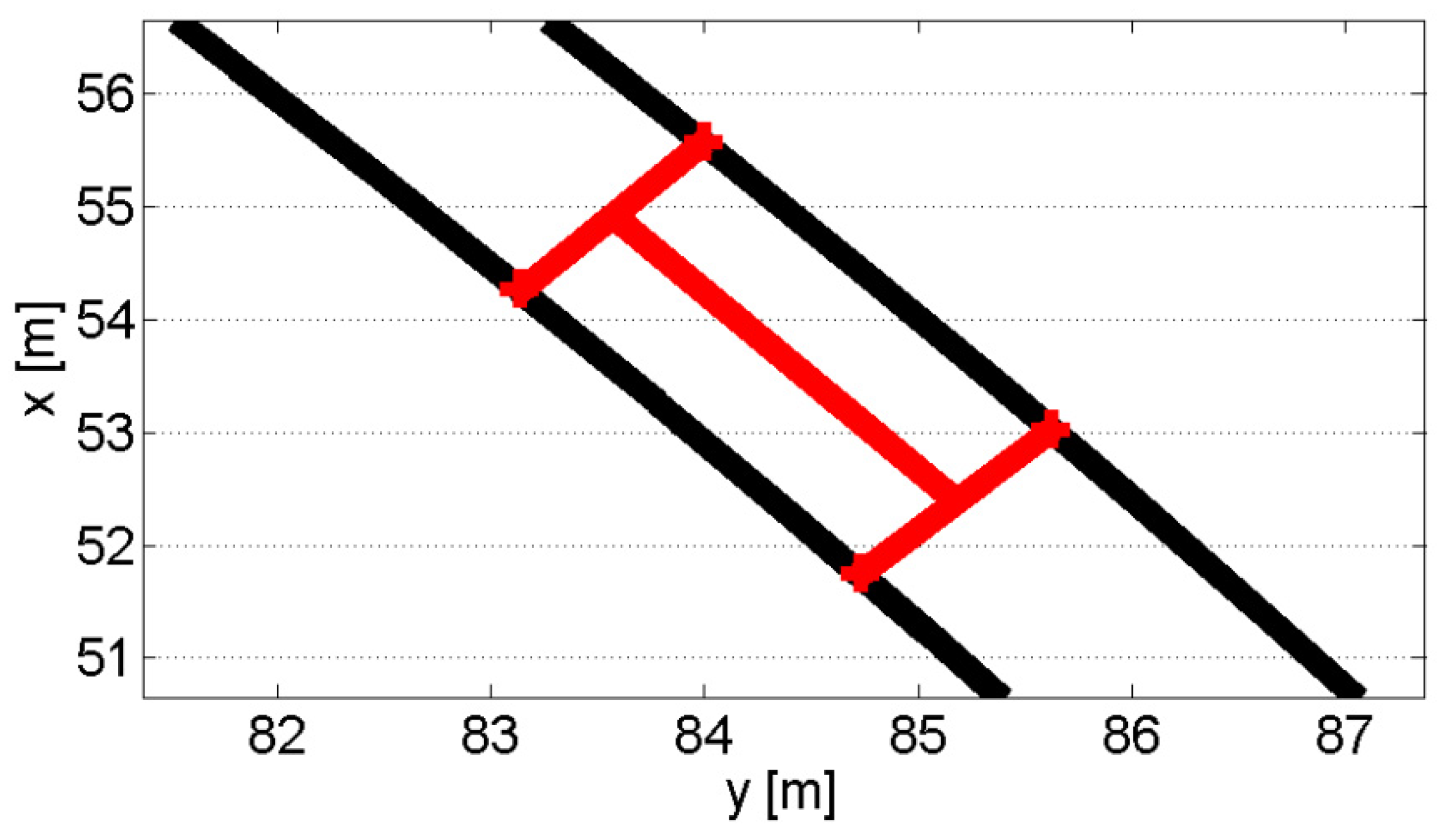
The possibilities of using the vector control system to drive a bogie with independently rotating wheels are investigated while moving along a curve of a track with a strictly defined radius (
Figure 18).
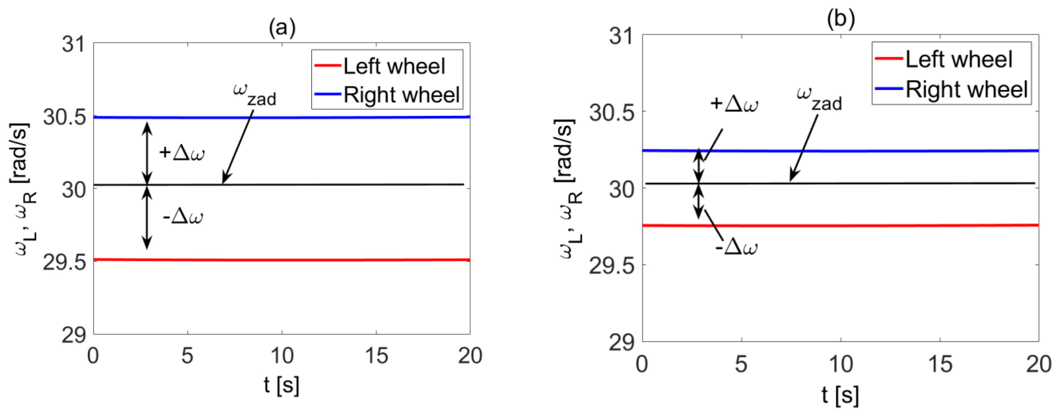
Figure 19a shows the speeds of individual wheels during the bogie’s movement along a track curve with a radius of 50 m, while
Figure 19b shows the speeds when the bogie moves along a 100 m radius. In both cases, the Field Oriented Control (FOC) method is used for controlling the railway bogie.
As it results from the presented results of the computer simulation (
Figure 19), the concept of the vector control system proposed in this paper allows the adjusting of the rotational speeds of individual wheels to different track radii occurring on the track curves. When the bogie moves along the curve of the track with a smaller radius, a greater difference in rotational speed between the individual wheels is obtained (
Figure 19a). On the other hand, when the bogie moves along a curve with a larger radius, the difference in rotational speeds between the wheels decreases (
Figure 19b).
In this paper just a concept of the control system for a single wheelset driven by induction motors is investigated using a simulation method. The results of experimental tests of this control system, carried out by the manufacturer before the implementation of this solution in the prototype of the vehicle, allowed for adjusting the system parameters to the actual operating conditions. Due to the manufacturer’s lack of consent to the presentation of the results, the authors cannot present them in this work. More than a dozen trams with this solution are currently operated in Poland by public transport operators.
6. Conclusions
This paper deals with the issue of drive control in low-floor trams in which, for design reasons, wheelsets with independently rotating wheels are installed in the bogies of such vehicles. Such a solution, due to the necessity to meet the basic requirements concerning the behavior of the vehicle on the track, requires the use of a system for controlling the angular speeds of the individual wheels of the bogie wheelsets so that the wheelsets move along the center line of the track. In this case, the concept of vector control of the induction motor is used, which allowed for indirect control of the angular velocities of the bogie wheels. The control system fulfills its role both when driving on curves of different radii and when driving on a straight track, when the center of mass of the bogie does not coincide with the center line of the track and then the rim of one of the wheels of the set is in constant contact with the rail, which results in a difference in the rotational speed of the left wheel compared to the right wheel. The vector control method used in this paper gives the possibility of simultaneous control of the rotational speed and electromagnetic torque of the motor, which is characterized by a better dynamic of the drive system compared to control with scalar methods. The proposed solution was implemented in a tram produced by Polish company. The implementation was preceded by numerous experiments made by the manufacturer before putting the vehicle into service. The innovation of the proposed solution consists in building a mathematical model of the electromechanical system, later used in the simulation model, and then used in the construction of a prototype of a low-floor tram vehicle.
As with any research method, the proposed solution has limitations in application resulting from the specifics of the real object. Since simulation tests are always burdened with an error resulting from the accuracy of the adopted model, the implementation of the method in the solution used in a prototype requires research and experiments in order to select the parameters of the control system to the actual operating conditions of the vehicle. The method can also be used in the case of railway vehicles with other parameters (geometric parameters, elastic–damping parameters, and mass–inertia parameters) and may also be used for a scale model of the vehicle. Currently, 50 such trams are operated in Warsaw.


 ,
, 
