Article

Numerical Simulation of the Flow and Heat Transfer Characteristics of Sweeping and Direct Jets on a Flat Plate with Film Holes

1
School of Energy, Power and Mechanical Engineering, North China Electric Power University, Beijing 102206, China
2
Key Laboratory of Light-Duty Gas-Turbine, Institute of Engineering Thermophysics, Chinese Academy of Sciences, Beijing 100190, China
3
University of Chinese Academy of Sciences, Beijing 100049, China
*
Author to whom correspondence should be addressed.
Energies 2022, 15(12), 4470; https://doi.org/10.3390/en15124470
Submission received: 10 May 2022 / Revised: 2 June 2022 / Accepted: 14 June 2022 / Published: 19 June 2022
(This article belongs to the Special Issue Flow and Heat Transfer in Turbomachinery)

Abstract

:
The internal heat transfer performance and flow structures of a sweeping jet and film composite cooling on a flat plate were numerically studied. Sweeping jet and film composite cooling consists of a fluidic oscillator and 20 cylindrical film holes; the direct jet is formed by removing the feedback from the fluidic oscillator, which is different from the traditional cylindrical nozzle. Four different mass flow rates of coolant were considered, and the inclination angle of the film hole was 30°. The Conjugate Heat Transfer method (CHT) and Unsteady Reynolds Averaged Navier Stokes equation (URANS) were employed. The results indicated that the flow resistance coefficients of the sweeping jet were larger than those of the direct jet, and the Nusselt number monotonously increased with the increase in the mass flow rate. Compared to the direct jet, the sweeping jet had a more spatially uniform heat removal rate, and the area-averaged Nusselt number was slightly lower. Therefore, the sweeping jet and film composite cooling caused the distribution of the flat plate heat transfer to be more uniform. It is worth noting that the novel direct jet nozzle in the present work had considerable area-averaged impingement cooling effectiveness.

1. Introduction

The leading edge of the active blade usually adopts the impingement and film composite cooling structure to reduce the heat load. Hollworth [1] first studied impingement and film composite cooling in 1980; the results showed that the impingement cooling effectiveness of the composite cooling was improved when the thickness of the boundary layer near the film holes was reduced. Therefore, film holes have a profound effect on the flow structure inside the impingement chamber. Moreover, Ekkad [2] found that the crossflow in the impingement chamber only developed in one direction due to the suction effect of the film holes, and the impingement cooling effectiveness was reduced. The study of Huber [3] also indicated that the film holes weakened the cooling effectiveness of the adjacent impingement holes. In addition, research on the impingement and film cooling on a semi-cylindrical model [4,5] and the leading edge of the actual blades [6,7,8] has been conducted. Therefore, the previous literature shows that the addition of film holes leads to a decrease in the impingement cooling effectiveness.
The impingement cooling structure mentioned above is a traditional cylindrical nozzle, and it is sprayed directly on the target surface, which has a limited high cooling effectiveness area. To obtain a relatively uniform distribution of cooling effectiveness on the impinging surface, a vortex jet cooling structure is proposed; that is, the cylindrical nozzle is moved to one side of the semi-cylindrical model. In addition, a confined slot jet [9] or Nanofluid jet [10,11] can also obtain satisfactory impingement cooling effectiveness. Moreover, a fluidic oscillator is also used in the field of impingement cooling [12,13] because it can produce a sweeping jet with no moving parts. The fluidic oscillator is a patent proposed by Dr. Stouffer [14] in 1979, and it has been used with film holes [15,16,17,18] to enhance the heat transfer performance of blades.
Compared to a direct jet, a sweeping jet can impinge the coolant with the same mass flow relatively evenly in a larger area. Wu Yongjia [19] performed a Large Eddy Simulation on three configurations of impingement cooling, including an angled fluidic oscillator, a curved fluidic oscillator, and a direct jet. The results showed that the cooling effectiveness of the direct jet was the highest at the impinging point, but it decreased sharply downstream; conversely, the curved fluidic oscillator had a more uniform cooling effectiveness distribution. Hossain [13] numerically investigated the effects of the exit fan angle and jet distance on the impingement heat transfer of a fluidic oscillator. It was found that the sweeping jet increased the turbulence in the shear layer near the impinging surface, and the cooling effectiveness increased with the decrease in the exit fan angle and impinging distance. In addition, Osorio [20] found that there was no stagnation zone when the impinging distance was less than two, and the cooling effectiveness was the highest when the impinging distance was three. Kim [21] found that the cooling effectiveness of a sweeping jet was higher than a direct jet when the impinging distance was less than five. Significantly, Agricola [22] investigated the flow structures and heat transfer characteristics of a sweeping jet and a direct jet with different mass flow rates and turbulence on a low-speed cascade test rig. The experimental results showed that the impingement cooling effectiveness of the direct jet exceeded the sweeping jet, and the aerodynamic loss was smaller when the impinging distance was five. The reason for the divergence might be that the impinging surface was concave in the experiment of Agricola [22], large-scale vortices were formed on both sides of the jet core region, and the cooling effectiveness was reduced because the coolant with a higher temperature was sucked into the core region. In addition, the effect of solid heat conduction on the impingement cooling effectiveness needs to be considered. Compared to the wall boundary conditions with constant temperature or constant heat flux, the conjugate heat transfer method can achieve more actual convection boundary conditions; the predicted results of the conjugate heat transfer method perfectly matched the experimental results.
The review of the literature on the flow and heat transfer characteristics of the sweeping jet showed that there is hardly any research on a fluidic oscillator impinging on a flat plate with film holes, but the turbine blades in service usually have a composite cooling structure of an impinge nozzle and film holes. Therefore, in this paper, the sweeping jet and film composite cooling on a flat plate are investigated using the conjugate heat transfer method. A new type of direct jet, that is, removing the feedback loops of the fluidic oscillator, is also combined with the film holes to form a novel direct jet and film composite cooling structure, which is used for a comparative study with the sweeping jet and film composite cooling. The issues discussed in this paper are summarized as follows:
(1)
The internal and external flow structures and cooling effectiveness of the sweeping jet and novel direct jet combined with film holes are studied.
(2)
The solid domain and the fluid domain are combined into a flat plate computational domain through “interface” boundary conditions to simulate the leading-edge on the pressure side of actual turbine blades.
(3)
The flat plate model computational domain is calculated using the Unsteady Reynolds Averaged Navier Stokes equation (URANS) with the SST k-ω turbulence model for all working conditions.
(4)
The effect of four different mass flow rates of coolant (mc = 0.04 g/s, 0.08 g/s, 0.14 g/s, and 0.30 g/s) on the flow and heat transfer characteristics of the sweeping jet and direct jet are investigated.

2. Computational Method

2.1. Geometry Details

The fluidic oscillator used in the present work was adjusted from the invention of Bowles Fluidic Corporation [14]. The 3D view is shown in Figure 1; the overall size of the fluidic oscillator was 14 mm × 7 mm × 1 mm. The width of the fluidic oscillator throat was 1 mm, and it was set to “D”. The aspect ratio of the throat was one, which could obtain the highest sweep frequency [23]. The specific coordinate points of the fluidic oscillator profile are shown in Appendix A. The width and length of the impingement chamber were 7.5D and 32D, respectively, which were the same as those of the mainstream chamber and solid domain. The inlet of the mainstream chamber was expanded by 16D in order to ensure full development of the boundary layer of the mainstream. The distance between the throat of the fluidic oscillator and the impinging surface was 5D, and the exit fan angle was 100°, which could obtain a relatively higher impingement cooling effectiveness [13]. The height of the solid domain was D, where 4 × 5 cylindrical film holes with a diameter of 0.5D were located. Meanwhile, the distance between adjacent film holes in each row was 9D, and in each column was 1.5D; the inclination angle of the film holes was 30°. In addition, two feedback loops of the fluidic oscillator were removed; thus, the novel direct jet as a reference was established.

2.2. Mesh Procedure

The fluid domain was meshed using hexahedron grids and connected with the solid domain, which used tetrahedron grids by an interface boundary; the meshes close to the film holes and walls were refined to ensure the value of Y+ less than 1. The grid quality was checked and adjusted carefully to ensure better convergence (Figure 2).

2.3. Boundary Conditions and Numerical Setup

The specific boundary conditions are shown in Table 1. In all cases in the present work, air ideal gas was used in the fluid domain, the velocity inlet boundary condition was set to the inlet of the mainstream chamber, the mass flow rate inlet boundary condition was set to the coolant, the total temperature was set to 600 K at the mainstream inlet, the velocity was 20 m/s, the static pressure was set to 101,325 Pa at the mainstream outlet, the inlet turbulent intensity was 1%, and the inlet total temperature of the coolant was set to 300 K. Four different mass flow rates of coolant (0.04 g/s, 0.08 g/s, 0.14 g/s, and 0.30 g/s) were studied in the present work. Both side walls of the fluid and solid domain were set as translational periodic boundaries, the conjugate boundaries between the fluid domain and the solid domain were set as a general thermal coupling to transfer heat flux, and the non-slip adiabatic wall boundary was assigned to the rest surface. In addition, the thermal conductivity was set to 10 W/(m·K), which led to the Bi number in the present work being similar to the actual turbine blade [24]. Therefore, the wall heat flux and wall temperature were obtained by the parameters of the coolant, the mainstream, and the thermal conductivity of the solid domain.
For the solver control of CFX 19.0, the high resolution and second-order backward Euler methods were adopted for the advection and transient scheme. CFX is a fully coupled solver, which does not need pressure–velocity coupling as that is taken care of in the matrix solution. It takes more time per iteration and uses more memory as the matrix is larger, but it usually converges much faster. Due to the long convergence time of the transition model, the maximal coefficient loops for each timestep were set to 10, and the iteration continued until the root mean square residuals of the momentum, mass, energy, turbulent, and transition equations were lower than 10−6, which were same for the direct jet cases. In addition, the timesteps varied from 2 × 10⁻⁷ s to 5 × 10⁻⁶ s depending on the inlet velocity of the fluidic oscillator to keep the root mean square (RMS) courant number less than unity. As initial conditions, the steady results were used in the transient numerical simulation, which obtained time accurate and time-averaged results for the sweeping jet and the direct jet.
To evaluate the aerodynamic performance of the combined cooling configuration, the time-averaged flow resistance coefficient of the coolant was discussed in detail, and it is calculated by:
C f = P i n , c P o u t 0.5 ρ i n , g V i n , g 2
The Nu number was employed to represent the internal cooling performance, while the heat conduction of the solid domain was considered, and it is calculated by:
N u = h D j λ c = q w D j λ c ( T w T c )
where qw is the wall heat flux, Dj is the hydraulic diameter of the fluidic oscillator throat, λc is the thermal conductivity of coolant, Tc is the temperature of the coolant, and Tw is the temperature of the impinging surface (which is the side surface in contact with the coolant jet).
The overall cooling effectiveness (η) was used to evaluate the cooling performance. The heat conduction of the solid domain was considered and calculated by:
η = T g T o s T g T c
where Tg is the total temperature of the mainstream inlet, Tc is the total temperature of the coolant inlet, and Tos is the outer surface (which is the side surface in contact with the mainstream) temperature of the cooled plate.
The Strouhal number is the dimensionless sweep frequency of the sweeping jet, and its definition is as follows:
S t = f D j V j
where f is the sweep frequency of the sweeping jet, and Vj is the average velocity at the throat of the fluidic oscillator.

2.4. Validation Analysis

For the numerical simulations of the sweeping jet and film composite cooling, the sweep frequency of the fluidic oscillator and heat transfer performance were strongly influenced by the turbulence model. The SST k-ω model of Menter [25] for a sweeping jet was employed in previous works, and their results are in good agreement with the experimental results [12,13,15]. In addition, the aerodynamic and heat transfer results of the SST k-ω model were similar to the results of the Large Eddy Simulation [19]. Further, details on the selection of the turbulence model in a numerical simulation of the combination of impingement and film cooling were investigated in Liu Zhao’s paper [26], which demonstrated that the SST k-ω model obtained the highest accuracy.
The experimental case investigated by Hossain [12] was adopted as the model verification; the shape of the fluidic oscillator and the aspect ratio of the fluidic oscillator throat was the same as that employed in the present work. As shown in Table 2, the results demonstrated that the SST k-ω model agreed well with experimental results. The experimental results of Agricola et al. [27] were selected to compare the Nu number distribution of the sweeping jet on a smooth target surface. The size and boundary conditions of the calculation model were the same as those in the experiment. In the experiment, the ratio of the distance between the throat and the target surface to the hydraulic diameter (H/D) was 6, and the Re number was 35,000. Figure 3 shows the comparison between the simulation results of the spanwise-averaged Nu number on the target surface of the sweeping jet and the experimental results in reference [27]; the standard k-ε and RNG k-ε models overestimated the heat transfer effectiveness, while the calculated results of the SST k-ω model were basically consistent with the experimental data. Therefore, the SST k-ω model was adopted for the present work.

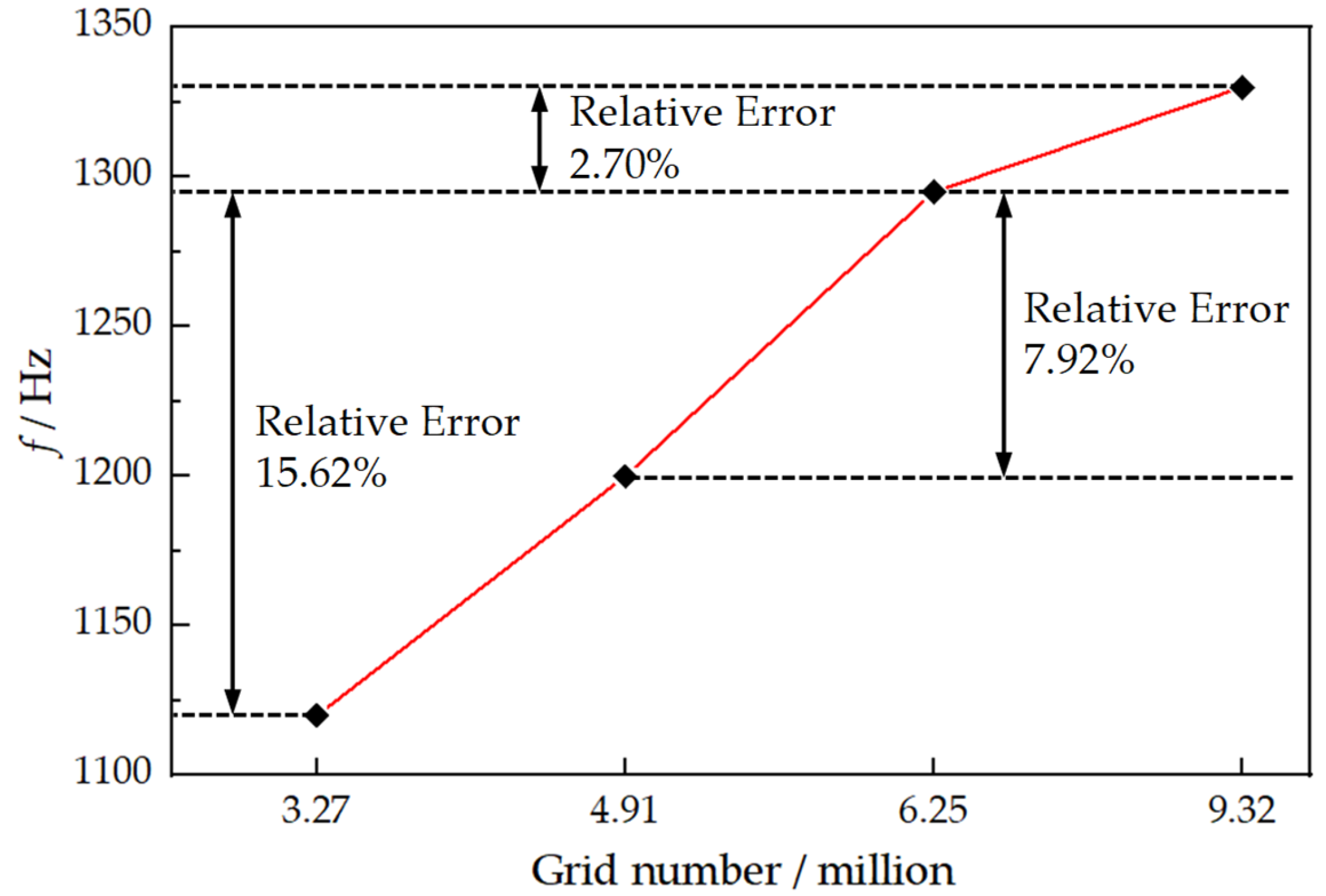
2.5. Grid Independency

A grid independence analysis was carried out to balance the accuracy of the computational results and the grid number. The comparison of the sweep frequency of the fluidic oscillator was conducted based on 4 different grid numbers at mc = 0.08 g/s. As shown in Figure 4, it is observed that the calculated results for the case of 4.91 million grids were a little lower than those with more meshes. However, the calculated results for the case with 6.25 million grids had a good agreement with the case with 9.32 million grids. Thus, about 6.25 million grids were used in the following simulations, considering the calculation cost.

3. Results and Discussions
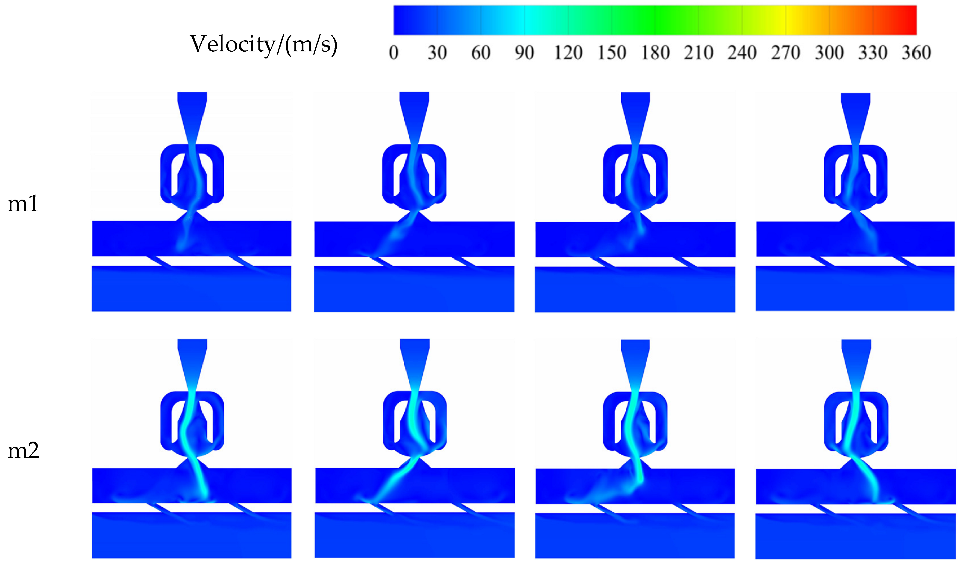
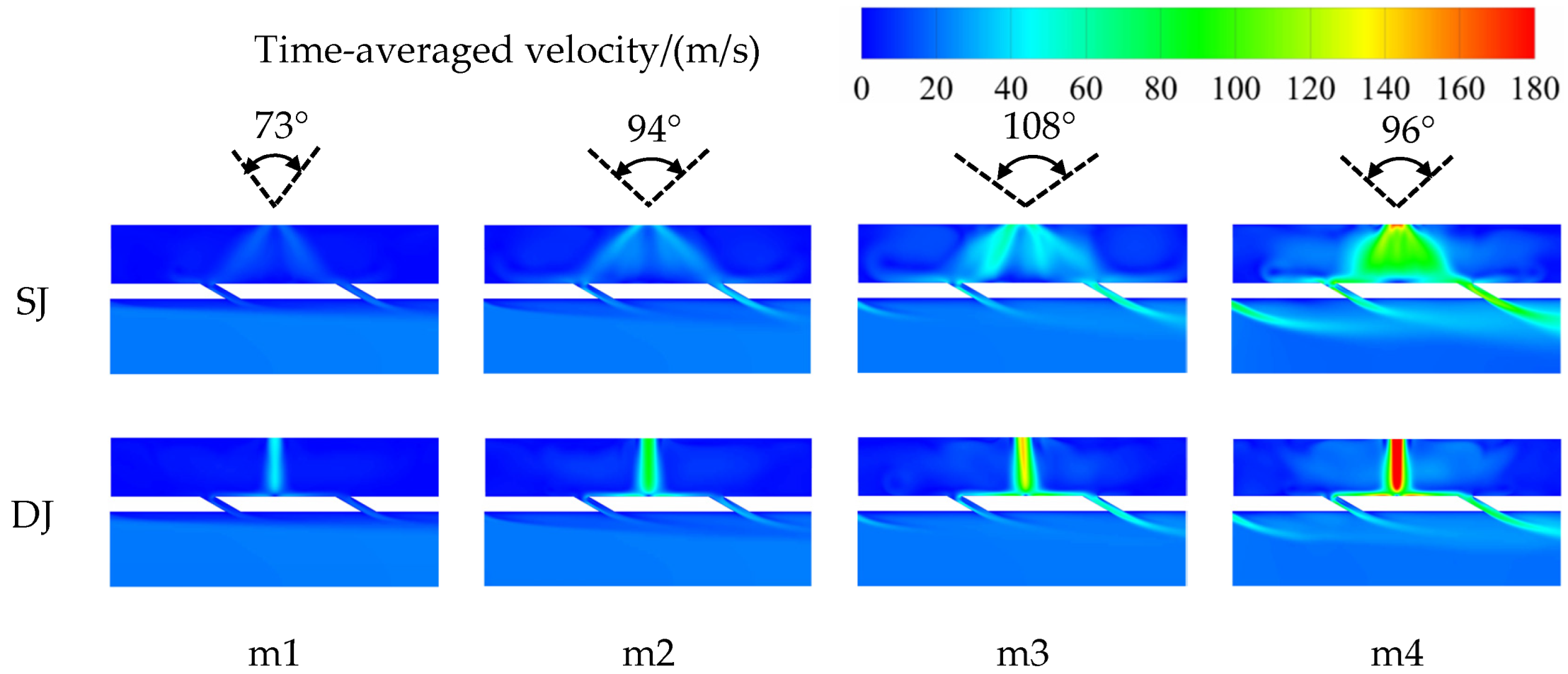
3.1. Flow Structure

Figure 5 shows the time-accurate velocity magnitude (Front view) for α = 30° case at 4 mass flow rates of coolant for half a sweep period. The impingement of the fluidic oscillator matched the direct jet that rotated around an axis, sweeping from leftmost to rightmost in half a period; meanwhile, the lateral velocity of the coolant was increased by the sweeping behavior near the impinging surface. In addition, the jet velocity inside the impingement chamber increased with the increase in mass flow rate, but the deflect angle did not increase monotonically. The deflect angle is defined as the angle between the leftmost and rightmost jet (Figure 6 shows the specific values of the deflect angle); it first increased when the mass flow rate increased from 0.04 g/s to 0.14 g/s, but it became small due to the supersonic flow at the throat of the fluidic oscillator when the mass flow rate was 0.30 g/s. Previous studies [28] have shown that when the Ma > 0.5, the fluid in the fluidic oscillator begins to be compressed, resulting in an increase in density. With the increase in the inlet mass flow rate, the increase in density gradually exceeded the increase in velocity. When the velocity of the fluid at the throat of the fluidic oscillator reached the sound velocity, the increased mass flow rate could only further compress the fluid slightly; this caused the deflect angle to remain constant when the fluidic oscillator impacted the smooth surface. However, the reason why the deflect angle decreased when the velocity of the fluid at the throat of the fluidic oscillator reached the sound velocity in the present work was that most of the coolant was pumped out by the film holes. The extraction by the film holes accelerated the velocity of the coolant near the impinging surface, resulting in a thinner boundary layer, which was conducive to enhancing the internal heat transfer effectiveness. In addition, the momentum of the film fluctuated periodically with the sweeping behavior of the jet, as well. Therefore, the area covered by the coolant of the sweeping jet was relatively larger than that of the direct jet.
As depicted in Figure 6, the time-averaged velocity contours were observed for the sweeping jet and the direct jet at four mass flow rates. Clearly, there were some distinct features of the direct jet on the impinging surface, a stagnation region with peak velocity occurred, and the coolant flowed out evenly from the film holes at the corresponding positions. The velocity of the coolant near the impinging surface was faster when the mass flow rate increased, but the thickness of the film on the outer surface became larger.
The flow structures of the sweeping jet were different to those of the direct jet; there were two peak velocity regions on both sides of the impingement core region due to the sweeping behavior of the jet. Consequently, compared with the direct jet, the impingement flow generated by the fluidic oscillator covered a larger area. The coolant also tended to deviate from the impinging surface at the end of the impingement chamber. However, the film holes extracted the coolant, which tended to be separated from the impinging surface and formed a film on the outer surface, which weakened the strength of the large-scale vortex that affected the impingement cooling effectiveness [12]. Moreover, the mass flow rate of each hole fluctuated periodically with the sweeping jet, but the time-averaged results demonstrated that the film thickness on the outer surface was not significantly different from that of the direct jet at the same mass flow rate. Similar to the direct jet, the momentum of the sweeping jet increased with the increase in the mass flow rate, which led to an increase in the film momentum on the outer surface; thus, the ability to penetrate the mainstream was increased.
Table 3 demonstrates the values of the time-averaged flow resistance coefficient of the direct jet and the sweeping jet at different mass flow rates when the inclination angle is 30°. It is obvious that with the increase in the mass flow rate, the flow resistance coefficient of the sweeping jet was higher than the direct jet, which increased from 39.90% to 147.55%. Therefore, the growth rate of the flow resistance coefficient of the sweeping jet was much greater than the direct jet.

3.2. Internal Heat Transfer

In the previous literature, Park [29] and Kim [21] considered that the overall heat transfer coefficient could be increased by the sweeping jet, but Hossain [12] considered that the sweeping jet was at a disadvantage. Wu Yongjia [19] considered that the heat transfer coefficient in the core region of the direct jet was higher than the sweeping jet, but it decreased sharply outside the core region, and the coverage area and uniformity of the sweeping jet were higher than the direct jet. In this section, whether similar conclusions will be drawn using a flat plate with film holes is investigated. Unlike their traditional direct jet nozzle, the direct jet nozzle in the present work was formed by removing two feedback loops from the fluidic oscillator, which can easily use the same set of boundary conditions for the direct jet and the sweeping jet. The novel direct jet nozzle used in the present work made the heat transfer results of the comparative study of the sweeping jet and the direct jet interesting.
The time-averaged Nusselt number contours of the impinging surface at α = 30° for different mass flow rates are shown in Figure 7. Obviously, the high overall Nu number region of the direct jet corresponded to the stagnation region of the velocity contours, which were located at the jet core and the inlets of the film holes. In addition, different from the direct jet, which had a single peak, two distinct peaks occurred on the impinging surface of the sweeping jet. According to Kim’s conclusion [21], the dwelling time of the coolant on both sides of the fluidic oscillator was about 70% of the whole sweeping period; therefore, there were two peak values of the Nu number distribution on both sides of the impinging surface. With the increase in the mass flow rate, the area of the high Nu number of both the direct and sweeping jets increased (the high Nu number is defined as Nu > 20), and the area of the high Nu number of the sweeping jet was higher than that of the direct jet at the identical mass flow rate. Therefore, the sweeping jet had the advantage of evenly distributing coolant to obtain a relatively uniform Nu number distribution.
The Nu number value near the film holes was relatively higher, which is because the suction effect of the film holes increases the velocity of the coolant, resulting in the convective heat transfer coefficient being higher than in the downstream region. For the direct jet, the shape of the Nu number distribution was circular when mc = 0.04 g/s, and when mc > 0.08 g/s, the shape of the Nu number distribution was elliptical, which indicated that the existence of the film holes effectively weakened the lift-off effect of the coolant on the impinging surface. Similarly, the internal heat transfer effectiveness of the sweeping jet was affected by the film holes, as well. When the jet swept to the left, the suction of the right film holes caused a part of the coolant to flow to the right against the impinging surface. This flow structure caused the Nu number at the jet core to be almost equal to the peak value of the Nu number on both sides. For example, in the area where the Nu number was greater than 20 at mc = 0.08 g/s and mc = 0.14 g/s, its distribution was basically consistent.
Table 4 lists the area-averaged Nu number of the direct and sweeping jets at different mass flow rates. When the mass flow rate was in the range of 0.04–0.14 g/s, compared with the direct jet, the sweeping jet showed an average 9.31% decrease in heat transfer capability. However, the heat transfer capability of the sweeping jet was 5% higher than the direct jet at mc = 0.30 g/s. This is because the supersonic phenomenon in the fluidic oscillator had a profound impact on the flow structure of the coolant, and the deflection angle of the coolant decreased; thus, the momentum dissipation in the mainstream direction was reduced, and the impingement strength increased severely. Therefore, the heat removal performance of the sweeping jet was lower than that of the direct jet excluding mc = 0.30 g/s when the impinging distance was 5.
According to Table 4, the area-averaged Nu number of the sweeping jet and the direct jet was a monotonic function of the mass flow rate at the inlet of the coolant, and their mapping relationship can be fitted into a correlation that can accurately predict the Nu number within a certain range. The mapping relationship between the Nu number and the coolant inlet mass flow rate is defined as:
Y = a X b
The constant a and the exponent b are calculated by regression analysis of different data using the software MATLAB 2017a. The desired correlation of the sweeping jet is as follows:
N u _ S J = 65.44 m c 0.7881
The desired correlation of the direct jet is as follows:
N u _ D J = 47.08 m c 0.6133
where 0.04 g/s ≤ mc ≤ 0.30 g/s.

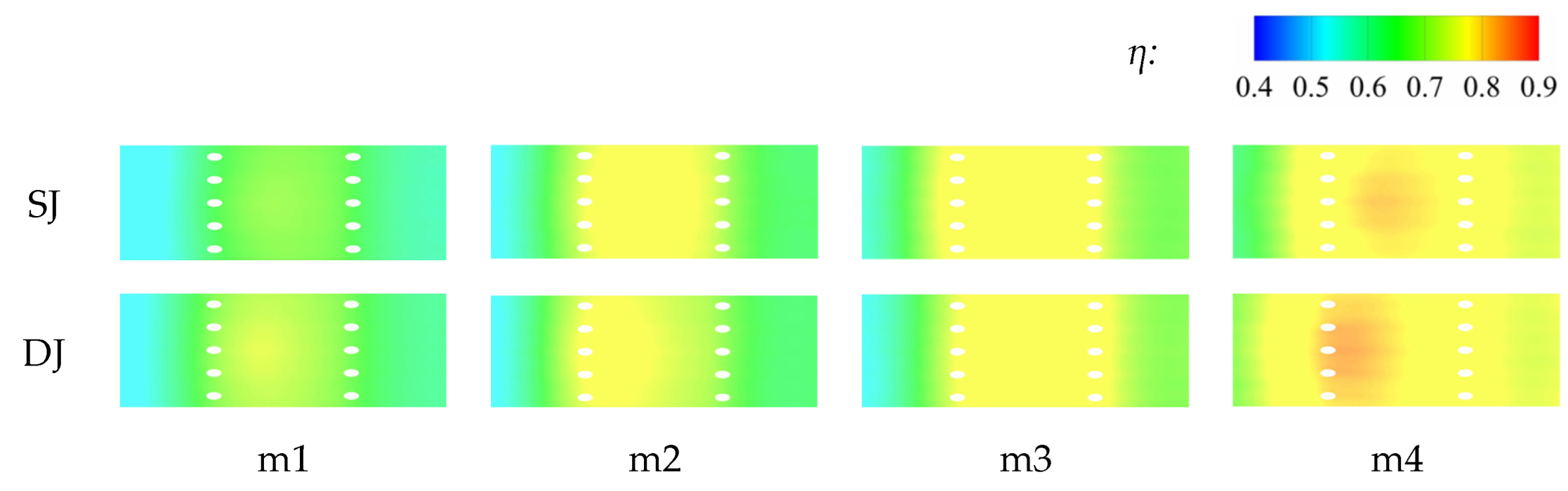
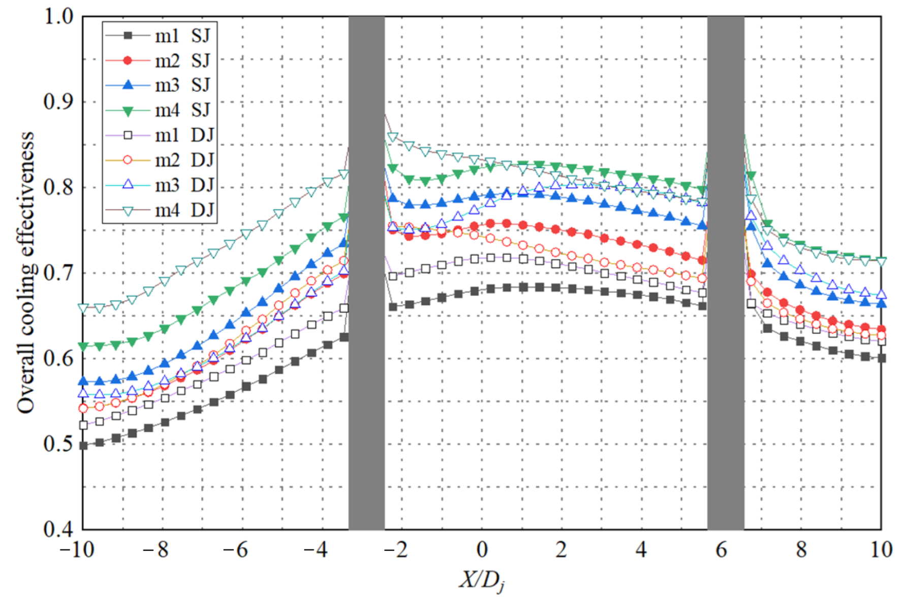
3.3. Overall Cooling Effectiveness

Figure 8 shows the time-averaged overall cooling effectiveness contours of the outer surface in different mass flow rates. Some obvious characteristics were observed for the fluidic oscillator and the direct jet. Due to the long dwelling time of the sweeping jet, the uniform overall cooling effectiveness near the orifices is vividly shown in Figure 8. Unlike the direct jet, which passively extracted the coolant, the sweeping jet actively blew a large amount of coolant into the film holes, which led to an increase in the outflow momentum of the coolant. The film adhered to the outer surface after being suppressed by the mainstream. However, the spanwise momentum of the film was lower than the streamwise momentum and continued to mix with the mainstream; the film gradually dissipated downstream of the orifices. Despite all this, due to the 3D heat conduction of the solid domain and the continuous film coverage, the overall cooling effectiveness difference between the center and the two peaks of the outer surface was not as obvious as the Nu number of the impinging surface. In addition, to further demonstrate the differences in the overall cooling effectiveness between the direct jet and the sweeping jet, the area-averaged overall cooling effectiveness of the direct and sweeping jets at different mass flow rates are listed in Table 5.
When compared with the direct jet, the sweeping jet illustrated a −0.9%~3.8% decrease in heat transfer capability. Therefore, the heat removal performance of the sweeping jet was lower than the direct jet excluding mc = 0.08 g/s when the impinging distance was 5. The reason is mainly that the momentum of the coolant was quickly weakened due to the large impinge distance, the sweeping jet did not reach its full potential of impingement heat transfer, and the novel direct jet nozzle structure in the present work was different from the traditional cylindrical nozzle. Its nozzle shape was “contraction–expansion–contraction–expansion”, so the compressible air experienced two accelerations in its interior. Moreover, it removed the feedback loops from the fluidic oscillator; the pressure loss of the compressible air in its interior was less than that of the fluidic oscillator, so the momentum of the direct jet was slightly higher than that of the sweeping jet, and the internal cooling effectiveness of the direct jet was slightly higher than that of the sweeping jet. From the comparison results of the overall cooling effectiveness, the area-averaged cooling performance of the direct jet was still higher than that of the sweeping jet. However, the direct jet nozzle in the present work has some disadvantages. If the mass flow rate was relatively smaller or higher, the coolant flowed randomly along the left wall or the right wall when passing through the direct jet nozzle due to the Coanda effect, resulting in the inclination of the direct jet. The other reason is that the ratio of the internal impingement cooling effectiveness and the external cooling effectiveness in the overall cooling effectiveness was more harmonious in the structure of the sweeping jet and film composite cooling when mc = 0.08 g/s.
Figure 9 indicates the effect of the mass flow rate on the overall cooling effectiveness along the streamwise midline of the outer surface. It can be observed that the overall cooling effectiveness increased with the mass flow rate in the case of the sweeping and direct jets; the sweeping jet provided a desirably flat profile, while the direct jet exhibited the typical non-uniform profile. That is because, with the increase in the mass flow rate, the frequency of the sweeping jet was higher, and the internal cooling effectiveness on the impinging surface was higher and more uniform, while the momentum of the direct jet was higher, and the peak value of the core area became higher. However, it was obviously found that the overall cooling effectiveness of the sweeping jet seldom exceeded that of the direct jet in the core region of the outer surface (−2 ≤ X/Dj ≤ 4), although most of the film obtained a large momentum to penetrate the mainstream when the mass flow rate was too large (mc = 0.30 g/s); however, the overall cooling effectiveness kept increasing with the mass flow rate.

4. Conclusions

To investigate the flow structure and heat transfer performance of the sweeping jet and film composite cooling in the flat plate, four mass flow rates of coolant were considered. A conjugate heat transfer simulation was performed using ANSYS CFX 19.0 to investigate the Nu number and overall cooling effectiveness distribution for the sweeping and direct jets. The comparative study revealed that the sweeping jet and film composite cooling showed a more uniform heat removal performance than the direct jet and film composite cooling configuration.
(1)
With the increase in the blowing ratio, although the supersonic velocity in the domain resulted in the decrease in the deflection angle of the coolant at mc = 0.30 g/s, the sweeping frequency of the fluidic oscillator, the Nu number, and the overall cooling effectiveness increased monotonously in all cases. However, the maximum flow resistance coefficient appeared at mc = 0.30 g/s for the sweeping jet and film composite cooling.
(2)
The sweeping jet and film composite cooling had a more uniform heat removal performance but an excessive flow resistance coefficient compared to the direct jet and film composite cooling, especially at a relatively higher mass flow rate (mc = 0.30 g/s in this study). The overall cooling effectiveness of the sweeping jet and film composite cooling was slightly higher than that of the direct jet and film composite cooling only when mc = 0.08 g/s.
(3)
The novel direct jet nozzle employed in the present work was formed by the fluidic oscillator, which removed the feedback loops; thus, the pressure loss of the compressible air in it was less than that of the fluidic oscillator. Therefore, the momentum of the direct jet was slightly higher than that of the sweeping jet, and the cooling effectiveness of the direct jet was slightly higher than that of the sweeping jet. However, the direct jet nozzle in the present work had some disadvantages; the direct jet randomly tilted to the left or right because of the Coanda effect when the mass flow was relatively small or large.

Author Contributions

X.K.: Conceptualization, methodology, software, validation, writing—original draft, visualization. Y.Z.: Conceptualization, project administration, funding acquisition, supervision. G.L.: investigation, data curation. X.L.: investigation, formal analysis, visualization. J.Z.: project administration, resources. J.X.: Conceptualization, methodology, software, writing—review and editing, supervision. All authors have read and agreed to the published version of the manuscript.

Funding

This research was funded by the National Natural Science Foundation of China (Nos. 51876202 and 51976214) and the National Science and Technology Major Project of China (J2019-II-0002-0022, 2017-IV-0010-0047).

Institutional Review Board Statement

Not applicable.

Informed Consent Statement

Not applicable.

Data Availability Statement

Not applicable.

Conflicts of Interest

The authors declare no conflict of interest.

Nomenclature

The following nomenclature are used in this manuscript:
DjHydraulic diameter of exit throat [m]
Y+Non-dimensional distance = (Y·uτ)/υ
YThickness of first grid [m]
uτShear velocity [m/s]
υKinematic viscosity [m2/s]
TTemperature [K]
VVelocity [m/s]
PPressure [Pa]
ρDensity [kg/m3]
CfFlow resistance coefficient as given by Equation (1)
NuNusselt number as given by Equation (2)
qwHeat flux of impinging surface [J/(m2·s)]
λcThermal conductivity of coolant [w/(m·K)]
fFrequency of the fluidic oscillator [Hz]
ηOverall cooling effectiveness as given by Equation (3)
αInclination angle of film holes [°]
ΦPhase angle [°]
SJSweeping jet
DJDirect jet
StStrouhal number

Subscripts

The following subscripts are used in this manuscript:
jExit throat of the fluidic oscillator
cCoolant
gMainstream
outOutlet of mainstream
wImpinging surface
inInlet

Appendix A. Coordinate Set

Table A1. Coordinate set of fluidic oscillator profile.
No.XYNo.XYNo.XYNo.XY
18.1332.503412.194.04675.000.931009.696.84
22.1920.843511.884.04685.310.781019.386.84
38.7520.843611.564.20695.630.621029.067.00
49.3820.683711.254.35705.93750.621038.757.15
510.3120.533810.944.35716.250.471048.447.31
610.9420.373910.314.51726.560.311058.137.46
711.5620.224010.004.67736.880.161068.1312.28
812.1920.06419.694.67747.190.001077.8112.44
912.8119.90429.384.67750.000.001087.8112.91
1013.1319.75439.064.51765.9418.041097.5013.06
1113.4419.59448.754.35776.8818.041107.5013.37
1213.7519.44458.444.20787.1918.041117.1913.53
1314.0619.28468.134.04797.5018.041127.1913.68
1414.3819.13477.813.89807.8117.891136.8813.84
1514.6918.97487.503.73818.1317.731146.8814.00
1615.0018.82497.193.58828.4417.731156.5614.15
1715.3118.66506.883.42838.7517.571166.2514.30
1815.6318.50516.563.27849.0617.421176.2514.46
1915.9418.35526.253.11859.3817.261185.9414.77
2016.2518.19535.632.95869.6917.111195.6314.93
2116.5618.04543.132.958710.0016.951205.6315.08
2216.5617.88552.812.808810.3116.791215.3115.24
2316.8817.57562.502.648910.6316.641225.3115.71
2417.1917.26572.192.499010.9416.481235.0015.86
2517.5016.95582.192.339110.9416.171245.0016.17
2617.505.29592.502.189211.2516.021254.6916.33
2717.194.98602.812.029311.2515.551264.6916.64
2816.884.82613.131.879411.5615.391274.3816.79
2916.564.67623.441.719511.566.841284.3817.11
3016.254.51633.751.569611.256.691294.0617.26
3115.944.35644.061.409710.946.53
3215.634.20654.381.249810.316.53
3315.314.04664.691.099910.006.67

References

  1. Hollworth, B.R.; Dagan, L. Arrays of Impinging Jets with Spent Fluid Removal through Vent Holes on the Target Surface—Part 1: Average Heat Transfer. J. Eng. Power 1980, 102, 994–999. [Google Scholar] [CrossRef]
  2. Ekkad, S.V.; Huang, Y.; Han, J.C. Impingement Heat Transfer on a Target Plate with Film Cooling Holes. J. Thermophys. Heat Transf. 1999, 13, 522–528. [Google Scholar] [CrossRef]
  3. Huber, A.M.; Viskanta, R. Effect of jet-jet spacing on convective heat transfer to confined, impinging arrays of axisymmetric air jets. Int. J. Heat Mass Transf. 1994, 37, 2859–2869. [Google Scholar] [CrossRef]
  4. Metzger, D.E.; Bunker, R.S. Local Heat Transfer in Internally Cooled Turbine Airfoil Leading Edge Regions: Part II—Impingement Cooling With Film Coolant Extraction. J. Turbomach. 1990, 112, 459–466. [Google Scholar] [CrossRef]
  5. Taslim, M.E.; Pan, Y.; Spring, S.D. An Experimental Study of Impingement on Roughened Airfoil Leading-Edge Walls with Film Holes. In Proceedings of the ASME Turbo Expo 2001: Power for Land, Sea, and Air, New Orleans, LA, USA, 4–7 June 2001; p. GT2002-30477. [Google Scholar]
  6. Ravelli, S.; Dobrowolski, L.; Bogard, D.G. Evaluating the Effects of Internal Impingement Cooling on a Film Cooled Turbine Blade Leading Edge. In Proceedings of the ASME Turbo Expo 2010: Power for Land, Sea, and Air, Glasgow, UK, 14–18 June 2010; pp. 1655–1665. [Google Scholar]
  7. Guo, Q.L.; Liu, C.L.; Zhu, H.R.; Liu, H.Y.; Wang, R.D.; Gao, C. Investigation on the Leading Edge Film Cooling of Counter-Inclined Cylindrical and Laid-Back Holes With and Without Impingement: Part I—Film Cooling Effectiveness. In Proceedings of the ASME Turbo Expo 2018: Turbomachinery Technical Conference and Exposition, Oslo, Norway, 11–15 June 2018; p. GT2018-76061. [Google Scholar]
  8. Mathew, S.; Ravelli, S.; Bogard, D.G. Evaluation of CFD Predictions Using Thermal Field Measurements on a Simulated Film Cooled Turbine Blade Leading Edge. J. Turbomach. 2012, 135, 011021. [Google Scholar] [CrossRef] [Green Version]
  9. Hussain, S.; Ismael, M.A.; Chamkha, A.J. Impinging jet into an open trapezoidal cavity partially filled with a porous layer. Int. Commun. Heat Mass Transf. 2020, 118, 104870. [Google Scholar] [CrossRef]
  10. Selimefendigil, F.; Chamkha, A.J. Cooling of an isothermal surface having a cavity component by using CuO-water nano-jet. Int. J. Numer. Methods Heat Fluid Flow 2020, 30, 2169–2191. [Google Scholar] [CrossRef]
  11. Selimefendigil, F.; Oztop, H.F.; Chamkha, A.J. Jet Impingement Heat Transfer of Confined Single and Double Jets with Non-Newtonian Power Law Nanofluid under the Inclined Magnetic Field Effects for a Partly Curved Heated Wall. Sustainability 2021, 13, 5086. [Google Scholar] [CrossRef]
  12. Hossain, M.A.; Agricola, L.; Ameri, A. Effects of Curvature on the Performance of Sweeping Jet Impingement Heat Transfer. In Proceedings of the 2018 AIAA Aerospace Sciences Meeting, Kissimmee, FL, USA, 8–12 January 2018. [Google Scholar]
  13. Hossain, M.A.; Agricola, L.; Ameri, A.; Gregory, J.W.; Bons, J.P. Effects of Exit Fan Angle on the Heat Transfer Performance of Sweeping Jet Impingement. In Proceedings of the 2018 International Energy Conversion Engineering Conference, Cincinnati, OH, USA, 9–11 July 2018. [Google Scholar]
  14. Stouffer, R.D. Oscillating Spray Device. U.S. Patent 4151955, 1 May 1979. [Google Scholar]
  15. Hossain, M.A.; Prenter, R.; Lundgreen, R.K.; Ameri, A.; Gregory, J.W.; Bons, J.P. Experimental and Numerical Investigation of Sweeping Jet Film Cooling. J. Turbomach. 2017, 140, 031009. [Google Scholar] [CrossRef] [Green Version]
  16. Hossain, M.A.; Asar, M.E.; Gregory, J.W.; Bons, J.P. Experimental Investigation of Sweeping Jet Film Cooling in a Transonic Turbine Cascade. J. Turbomach. 2020, 142, 041009. [Google Scholar] [CrossRef]
  17. Hossain, M.A.; Ameri, A.; Gregory, J.W.; Bons, J.P. Sweeping Jet Film Cooling at High Blowing Ratio on a Turbine Vane. J. Turbomach. 2020, 142, 121010. [Google Scholar] [CrossRef]
  18. Hossain, M.A.; Agricola, L.; Ameri, A.; Gregory, J.W.; Bons, J.P. Sweeping Jet Film Cooling on a Turbine Vane. J. Turbomach. 2019, 141, 031007. [Google Scholar] [CrossRef]
  19. Wu, Y.; Yu, S.; Zuo, L. Large eddy simulation analysis of the heat transfer enhancement using self-oscillating fluidic oscillators. Int. J. Heat Mass Transf. 2019, 131, 463–471. [Google Scholar] [CrossRef]
  20. Osorio, A.; Hodges, J.; Zawati, H.; Fernandez, E.J.; Kapat, J.S.; Rodriguez, J. Impact of Sweeping Jet on Area-Averaged Impingement Heat Transfer. In Proceedings of the ASME Turbo Expo 2019: Turbomachinery Technical Conference and Exposition, Phoenix, AZ, USA, 17–21 June 2019. [Google Scholar]
  21. Kim, S.; Kim, H.D.; Kim, K. Measurement of two-dimensional heat transfer and flow characteristics of an impinging sweeping jet. Int. J. Heat Mass Transf. 2019, 136, 415–426. [Google Scholar] [CrossRef]
  22. Hossain, M.A.; Ameri, A.; Gregory, J.W.; Bons, J.P. Turbine Vane Leading Edge Impingement Cooling with a Sweeping Jet. In Proceedings of the ASME Turbo Expo 2018 Turbomachinery Technical Conference and Exposition, Oslo, Norway, 11–15 June 2018. [Google Scholar]
  23. Hossain, M.A.; Agricola, L.; Ameri, A.; Gregory, J.; Bons, J. Sweeping jet impingement heat transfer on a simulated turbine vane leading edge. J. Glob. Power Propuls. Soc. 2018, 2, 402–414. [Google Scholar] [CrossRef]
  24. Zhang, X.D.; Liu, J.J.; An, B.T. The investigations of slot film outflow used on the laminated cooling configuration. Int. J. Heat Mass Transf. 2019, 141, 1078–1086. [Google Scholar] [CrossRef]
  25. Menter, F.R. Two-equation eddy-viscosity turbulence models for engineering applications. AIAA J. 1994, 32, 1598–1605. [Google Scholar] [CrossRef] [Green Version]
  26. Liu, Z.; Ye, L.; Wang, C.; Feng, Z. Numerical simulation on impingement and film composite cooling of blade leading edge model for gas turbine. Appl. Therm. Eng. 2014, 73, 1432–1443. [Google Scholar] [CrossRef]
  27. Agricola, L.; Prenter, R.; Lundgreen, R.; Hossain, M.; Ameri, A.; Gregory, J.; Bons, J. Impinging Sweeping Jet Heat Transfer. In Proceedings of the 53rd AIAA/SAE/ASEE Joint Propulsion Conference, Atlanta, GA, USA, 10–12 July 2017. [Google Scholar]
  28. von Gosen, F.; Ostermann, F.; Woszidlo, R.; Nayeri, C.; Paschereit, C.O. Experimental Investigation of Compressibility Effects in a Fluidic Oscillator. In Proceedings of the 53rd AIAA Aerospace Sciences Meeting, Kissimmee, FL, USA, 5–9 January 2015. [Google Scholar]
  29. Park Tongil; Kara Kursat; Kim Daegyoum, Flow structure and heat transfer of a sweeping jet impinging on a flat wall. Int. J. Heat Mass Transf. 2018, 124, 920–928. [CrossRef]
Figure 1. Schematic of the model and boundary condition. (a) The Fluidic Oscillator [14], (b) The novel direct jet, (c) Computational domain and boundary conditions.
Energies 15 04470 g001aEnergies 15 04470 g001b
Figure 2. Local views of computation grids. (a) Mesh in periodic boundary, (b) Mesh on impinging surface, (c) Mesh of fluidic oscillator, (d) Mesh in solid domain.
Energies 15 04470 g002
Figure 3. Heat transfer comparison between experimental data [27] and different turbulence models for sweeping jet at Re = 35,000, H/D = 6.
Energies 15 04470 g003
Figure 4. Grid independence analysis.
Energies 15 04470 g004
Figure 5. Instantaneous velocity magnitude (front view) for α = 30° at various phase angles and mass flow rates.
Energies 15 04470 g005aEnergies 15 04470 g005b
Figure 6. Time-averaged velocity magnitude (front view) for α = 30° at various mass flow rates.
Energies 15 04470 g006
Figure 7. Time-averaged Nu number contours on the impinging surface at α = 30°.
Energies 15 04470 g007
Figure 8. Time-averaged overall cooling effectiveness contours upon the outer surface at α = 30°.
Energies 15 04470 g008
Figure 9. Overall cooling effectiveness along streamwise midline of outer surface in different mass flow rates.
Energies 15 04470 g009
Table 1. Boundary conditions of computational domain.
Mainstream temperature, Tg600 K
Mainstream inlet velocity, Vin,g20 m/s
Outlet static pressure, Pout101,325 Pa
Coolant flow inlet temperature, Tc300 K
Turbulence intensity, Tu1%
Mass flow rate, mcm1 = 0.04 g/s
m2 = 0.08 g/s
m3 = 0.14 g/s
m4 = 0.30 g/s
Table 2. Aerodynamic comparison between experimental data [12] and different turbulence models for sweeping jet at Re = 35,200, H/D = 5.
Turbulence ModelSt
SST k-ω0.0601
Standard k-ε0.0590
RNG k-ε0.0608
Experiment data0.0602
Table 3. The time-averaged flow resistance coefficient of the coolant flow.
mcSJDJ
0.04 g/s17.2312.32
0.08 g/s72.5651.02
0.14 g/s217.21133.48
0.30 g/s876.69354.24
Table 4. The Area-averaged Nu number on impinging surface.
mcSJDJ
0.04 g/s4.875.69
0.08 g/s9.0110.02
0.14 g/s14.0815.12
0.30 g/s25.2422.10
Table 5. The area-averaged overall cooling effectiveness.
mcSJDJ
0.04 g/s0.62470.6492
0.08 g/s0.68070.6744
0.14 g/s0.71640.7144
0.30 g/s0.75760.7746
Publisher’s Note: MDPI stays neutral with regard to jurisdictional claims in published maps and institutional affiliations.

