Article

Fault Detecting and Isolating Schemes in a Low-Voltage DC Microgrid Network from a Remote Village

by
Pascal Hategekimana
1,*,
Adria Junyent Ferre
2,
Joan Marc Rodriguez Bernuz
2 and
Etienne Ntagwirumugara
1
1
African Center of Excellence Energy for Sustainable Development, University of Rwanda, Kigali P.O. Box 3900, Rwanda
2
Electrical and Electronics Engineering Department, Imperial College London, London SW7 2BX, UK
*
Author to whom correspondence should be addressed.
Energies 2022, 15(12), 4460; https://doi.org/10.3390/en15124460
Submission received: 5 April 2022 / Revised: 13 May 2022 / Accepted: 18 May 2022 / Published: 19 June 2022

Abstract

:
Fault detection and isolation are important tasks to improve the protection system of low voltage direct current (LVDC) networks. Nowadays, there are challenges related to the protection strategies in the LVDC systems. In this paper, two proposed methods for fault detection and isolation of the faulty segment through the line and bus voltage measurement were discussed. The impacts of grid fault current and the characteristics of protective devices under pre-fault normal, under-fault, and post-fault conditions were also discussed. It was found that within a short time after fault occurrence in the network, this fault was quickly detected and the faulty line segment was efficiently isolated from the grid, where this grid was restored to its normal operating conditions. For analysing the fault occurrence and its isolation, two algorithms with their corresponding MATLAB/SIMULINK platforms were developed. The findings of this paper showed that the proposed methods would be used for microgrid protection by successfully resolving the fault detection and grid restoration problems in the LVDC microgrids, especially in rural villages.

1. Introduction

Fast and effective fault detecting and isolating in any DC microgrid (DCMG) is still challenging, where researchers are considering the application of DC circuit breakers (DCCBs) and relays for fault detecting and isolating the faulty part of the microgrid [1]. Microgrid systems are autonomous and independent systems, that are capable of self-controlling and protecting system necessities [2,3]. Several customers in rural LVDC distribution networks experienced long periods of electricity outages due to the lack of an appropriate strategy for network protection [4]. Therefore, protection is considered the backbone of the sustainability of any DCMG network. Different types of fault detection and isolation schemes that were previously used have been proposed in [5]. Instead, [6] classified the fault detection methods as current derivative protection, differential protection, distance protection, directional overcurrent protection, and overcurrent protection. The authors of [7] proposed another method for fault detection called the resistance-based method where the selection of the faulty branch was completed in a few milliseconds.
Comparing DC with AC microgrids (ACMG), DCMG has more advantages related to efficiency (no energy conversion), cost, and scalability [8]. The key challenges in protecting the DCMG network are the absence of procedures and standards as discussed in [9]. In smart DCMG networks, grid relays are installed on the protective equipment for sensing and controlling faults in the network, and communicating with their DAB converters [10]. The currently available protection schemes for LVDC consist of the shutdown of the whole network during the fault occurrence [11]. In this paper, the proposed LVDC microgrid protection with fault detection and isolation consists of quick fault detection and isolation of the faulty grid part, resulting in the grid restoration without shutting it down for a long time. According to [12], despite numerous advantages of DCMGs, their protection systems suffer from quite a lot of challenges such as grounding and lack of natural zero-crossing current. The high magnitude of the fault current change is a challenge for securing a DCMG and causes significant difficulties in establishing specific rapid methods for fault detection and isolation in the network [13]. In the LVDC microgrid, the rate of rising faults would be significantly high, resulting in the cause of severe damage to the MG structural components. Therefore, power protecting devices (PPDs) were employed for protecting the DCMG networks [14]. Referring to [15], it was reported that the perfect selection of the reclosing sequence of the grid is the major challenging technique in the grid protection system, which leads to the preventable whole grid system shutdown. Therefore, the purpose of this paper will be to select a suitable and quick method, where the faulty section would be isolated from the grid through the PPDs followed by automatic grid re-energisation. After being inspired by the above studies, the principal contributions of this paper are summarised as follows:
  • Detailed study of the LVDC microgrid networks, their topologies, possible faults in the LVDC microgrid, power protective devices, and fault protection method.
  • Selection of the suitable and quick method for fault detection and isolation of the faulty segment in the LVDC microgrid network to efficiently protect that network.
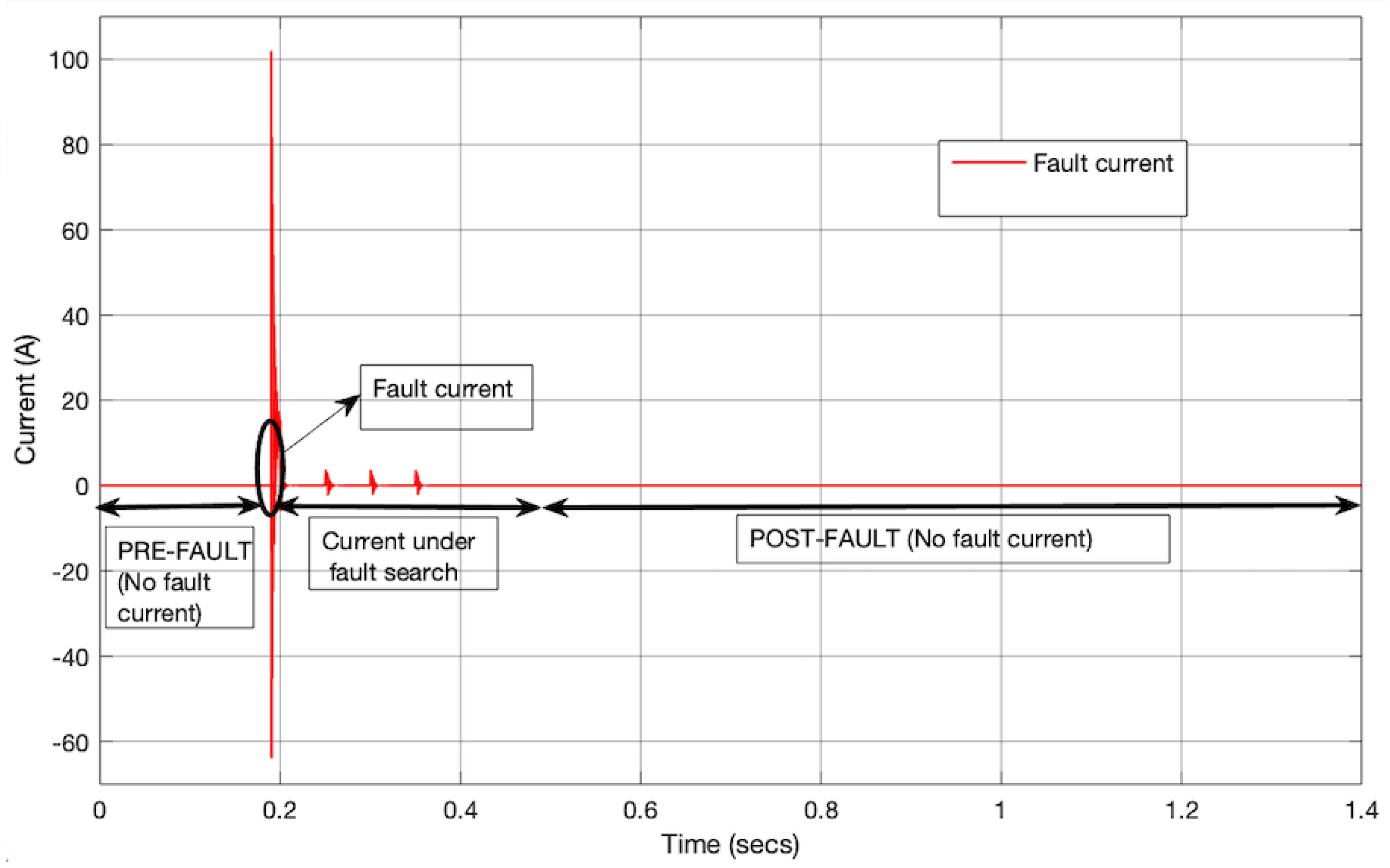
  • Analysis of the fault current into the LVDC microgrid.
The rest of this article is subdivided into five consecutive sections. Section 1 introduces the LVDC microgrid and the article’s contribution. Section 2 discusses the background of DCMG topologies and their protection systems. Section 3 discusses the materials and methods used to carry out this research. Section 4 presents the results and discussion of this work. Lastly, Section 5 discusses the conclusion of the paper.

2. Background of DC Microgrids and Their Protection Systems

In this section, typical microgrid topologies are discussed. Additionally, possible faults that most of the time happen in the DC microgrids with their protection methods are analysed. Protective devices, fault detection methods, and DCMG topology for fault detection are discussed. According to [16], DCMG protection is an important option for power system studies and the major objective of DCMG protection strategies is to improve the overall reliability of the system. Thus, a smart protection scheme could be provided such that it employs the flowchart which can solve the network protection problems due to the appropriately designed topologies [16]. For better grid protection performance, it is essential to reflect on the impacts of currents injected from DAB converters into the grid during fault occurrence. Since the fault is not detected, switches in converters are not blocked, and the control systems keep the normal control strategy during this period [17]. To determine the influence of fault current injected into the grid, it is essential to consider the converter control effects on the characteristics of the transient fault.
The DCMG topology can be categorised into three main types; (1) single bus, multi-bus, (2) meshed, and (3) loop or ring [18]. An example of a DCMG topology is presented in Figure 1, where different distributed energy systems (DESs) and DC loads are interconnected to form a ring-main type, where loads and power sources are interconnected to form a ring system. Comparing the ring type with other types, the ring-main topology was selected and its advantages compared to other topologies were analysed [19].

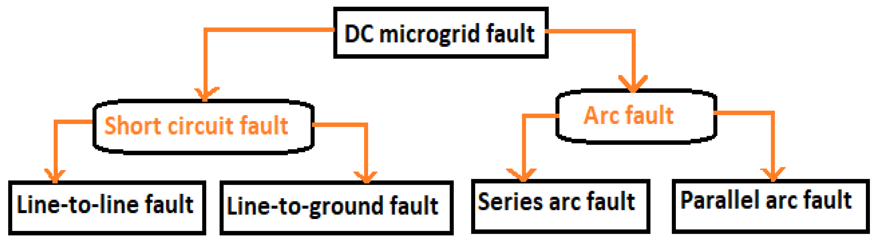
2.1. Possible Fault in DC Microgrid

The fault can happen at any segment of the grid network. The fault detection and isolation also may dramatically affect the grid system performance as a result of protection strategies [20]. When any fault occurs in a DCMG, it causes the fault current to go through an unsuitable path, resulting in damage to the system equipment, which also leads to a power outage. It was found that the danger of the grid fault depends on the fault current level, voltage level, and fault location [21]. The study of DCMC protection is mainly based on the control for grid stable operation. According to [22], the DC fault is classified into short-circuit and arc fault, as shown in Figure 2 [22,23], and in this work, short-circuit with line-to-line fault was considered. Two categories of short-circuit fault line-to-ground and line-to-line fault were discussed in [24]. Ground faults occur due to the objects falling on the power line, such as trees, which create a path to the ground [24]. The line-to-ground fault also occurs in the MG network due to the ageing of grid components and their physical contacts.
Line-to-line faults may result from an object falling across the negative and positive power lines. It may also happen during the switching device failure, which causes the power lines to be short [10]. It was found that during short-circuit fault in the DCMG, the line resistance will tend to zero or minimum value, while its current will tend to infinity or maximum value [25,26].

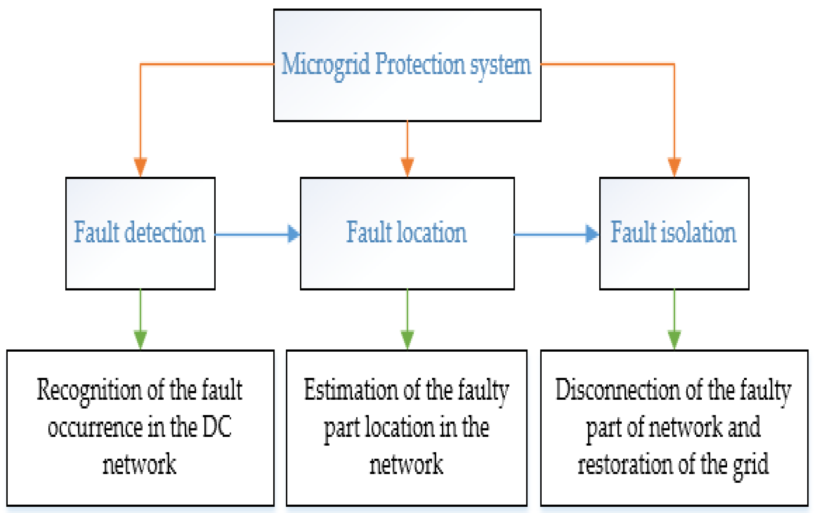
2.2. Network Protection and Fault Detection in the DCMG

The main objective of the protection scheme in the DCMG network is to quickly detect the fault and isolate it at any power line [27]. Thus, when the fault happens, the fault current in the DCMG would increase to 100 times the rated current. The main objective of smart MG protection when a fault is identified is that the trip signals must be sent to the DC circuit breaker for isolating the faulty section to prevent the MG components from being damaged [6]. The protection of DCMG systems employs numerous types of PPDs such as CBs and overcurrent relays [27]. The DCMGs can be protected by preventing them from reaching their current limit, where the grid components can be damaged [28].
In this work, the proposed flowchart for DCMG protection involving the process of detecting the fault up to its removal is shown in Figure 3. The DCMG presents some challenges for protection systems; refer to [1,27]. There is a difference in fault clearance in AC systems in comparison with DC systems [1]. The common methods used for fault detection in DCMGs were discussed in [2]. To optimise the time for short-circuit fault detection, different types of PPDs are used in DC systems [15]. According to [3], the requirements for a typical CB to be used for DCMG are described. First of all, this CB might be able to rapidly trip with adequate breaking aptitude. The five kinds of PPDs that are used for interrupting the DC fault are described in [29]. Important fault sequences from the event where the fault happened to that where the fault is isolated in a DCMG are developed in [30]. Thus, after fault locating, the quick restoration of the remaining non-faulty section of the MG line is desirable for ensuring a minimum power outage time [15]. According to [31], during the design of the protection strategy, the following factors must be considered: fault types, fault positions, and grounding system.
Normally, a DCMG system is working without fault. At the time the fault is occurring in the grid, proper fault localisation is essential for minimising the fault effects, otherwise, this would disturb the healthy sections of the MG. Referring to [32,33,34], the methods for localising a fault were discussed as follows: (1) The online-based fault localisation method and the key benefits of this method are (i) reliable, (ii) robust, (iii) capable, (iv) fast, and (v) able to accurately locate the fault [35]. (2) The offline-based fault localisation method, which is focusing on the pre-setting of the voltage or current threshold value in which the tripping signal will be given [33]. (3) Another method is applied by voltage or current measurement at each network bus, which can determine the abnormal changes in threshold MG ratings [27]. It was reported that a sudden decrease in the DC voltages and increase in current is considered as an indicating parameter for detecting the fault in the network [32]. In this paper, other methods for detecting a fault in the LVDC microgrid are proposed.

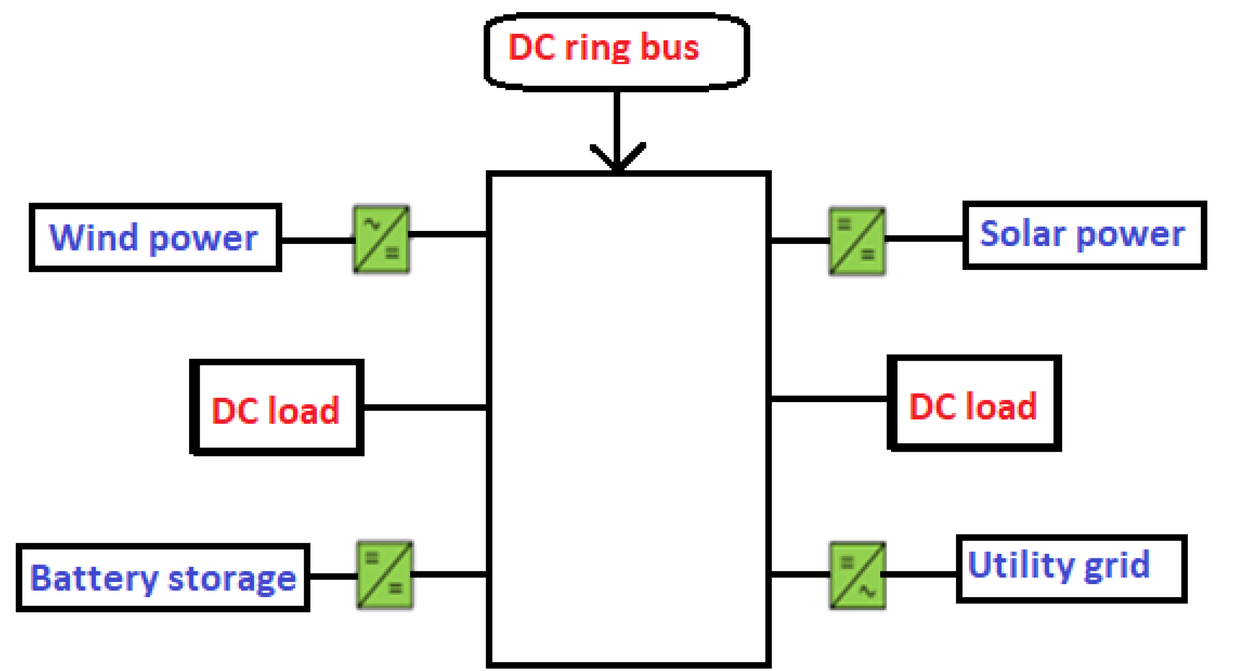
2.3. Rural Village LVDC Microgrid

At present, there is an increase in demand for LVDC microgrids compared with AC microgrids, where they are most commonly employed in rural villages. To meet the demands for the DC grid for electrifying the rural village, grid network protection is important [36]. In this work, the network topology is designed to be installed in a rural village, powered by the solar PV system with battery storage, and far away from the national grid. The grid network owner must improve the efficiency of electricity supplied from the MG to the rural customers. This is due to the increase in the system equipment failures and power supply outages; the system protection is critical once the fault has remained in the grid without being isolated [37]. Thus, rural MGs provide many benefits due to the replacement of the low-value energy resources being locally used with the higher-value energy resources for improving the community life standards including education, productivity, safety, and health [38]. It was concluded that the LVDC microgrid configurations can be proposed as suitable solutions that provide reliability to the electricity access for remote villages resulting in higher efficiency, the performance of load-sharing, stability, and aptitude of being coupled to other DC energy or storage units [39].

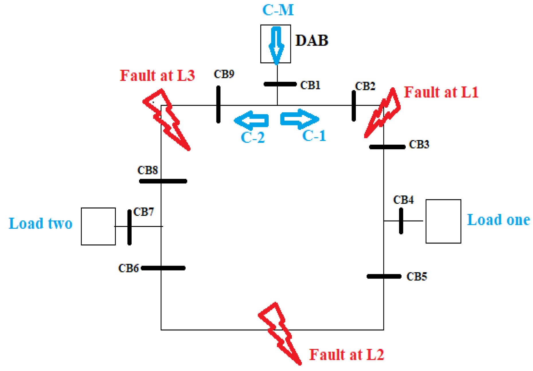
2.4. Proposed Topology for Fault Detection

The proposed structure from the previous work for the case study of Kagoma Village [19] was upgraded into Figure 4, which consists of a DC source, the DAB converter that creates the interface between the DC loads DC sources, two DC loads, and grid relays by considering a ring-main network type. Referring to [35], this DAB converter has capacitors that are connected to the load side of the DCMG for absorbing the higher-frequency ripple current. According to [40,41], this DAB converter possesses numerous advantages such as good power density, bidirectional power flow, galvanic isolation, etc. This is undertaken because the low impedance which is offered by the grid cable is not capable of limiting the high rate of the fault current rise. Referring to [42], it was reported that the ring-main distribution system has a noble system efficiency compared to the topologies for the case of a remote village.
In this paper, it was considered that under normal operation the DAB operates based on the conventional single-phase shift strategy. However, when the fault is detected, the DAB converter stops the feeding of current into the DC network and starts a checking mode where it injects pulses to determine whether a particular segment of the grid is faulty or not. Generally, the DAB converter is used to detect something wrong within the grid system and can block the fault current. The ring-main topology used in this paper is recognised as more expensive due to a greater number of grid relays, but it is resulting in additional advantages compared to other topology types [25].
The proposed LVDC ring-main system with possible fault occurrence and their respective relays is shown in Figure 4. To ensure the fault checking at each point shown in Figure 4, this circuit consists also of six-line segments, where segment one is composed of three circuit breaker relays (CB1, CB2, and CB9), segment two (CB2 and CB3), segment three (CB3, CB4, and CB5), segment four (CB5 and CB6), segment five (CB6, CB7, and CB8), and segment six (CB8 and CB9). In this paper, the process of fault detection according to Figure 4 is assumed clockwise, i.e., from CB1 to CB2 and ends at CB9. This is undertaken for simplification because the location where the fault is occurring is unknown, and from this reference direction, the faulty section will be determined. Initially, it is assumed that a current will flow from the grid source with the main current source (ICM), passing into the DAB converter (to boost the voltage source up to 200 V) and entering the ring-main network in two directions: C-1 and C-2, where C-1 denotes a right-side current direction (IC1) and C-2 denotes a left-side current direction (IC1), as formulated in Equation (1).
ICM = IC1 + IC2
From Figure 4, it is assumed that the faults can either happen in line 1 (between CB2 and CB3), line 2 (between CB5 and CB6), or line 3 (between CB8 and CB9). It is considered that there is no operator (human interaction) to suddenly remove the cause of the fault when this fault happens. Once the faulty line is successfully isolated and de-energised the current will be cut by the CB from that line, and only the current will flow from the remaining healthy grid side. The study of reclosing scheme in the LVDC microgrids could be used to significantly expand the reliability of MG operation [1].

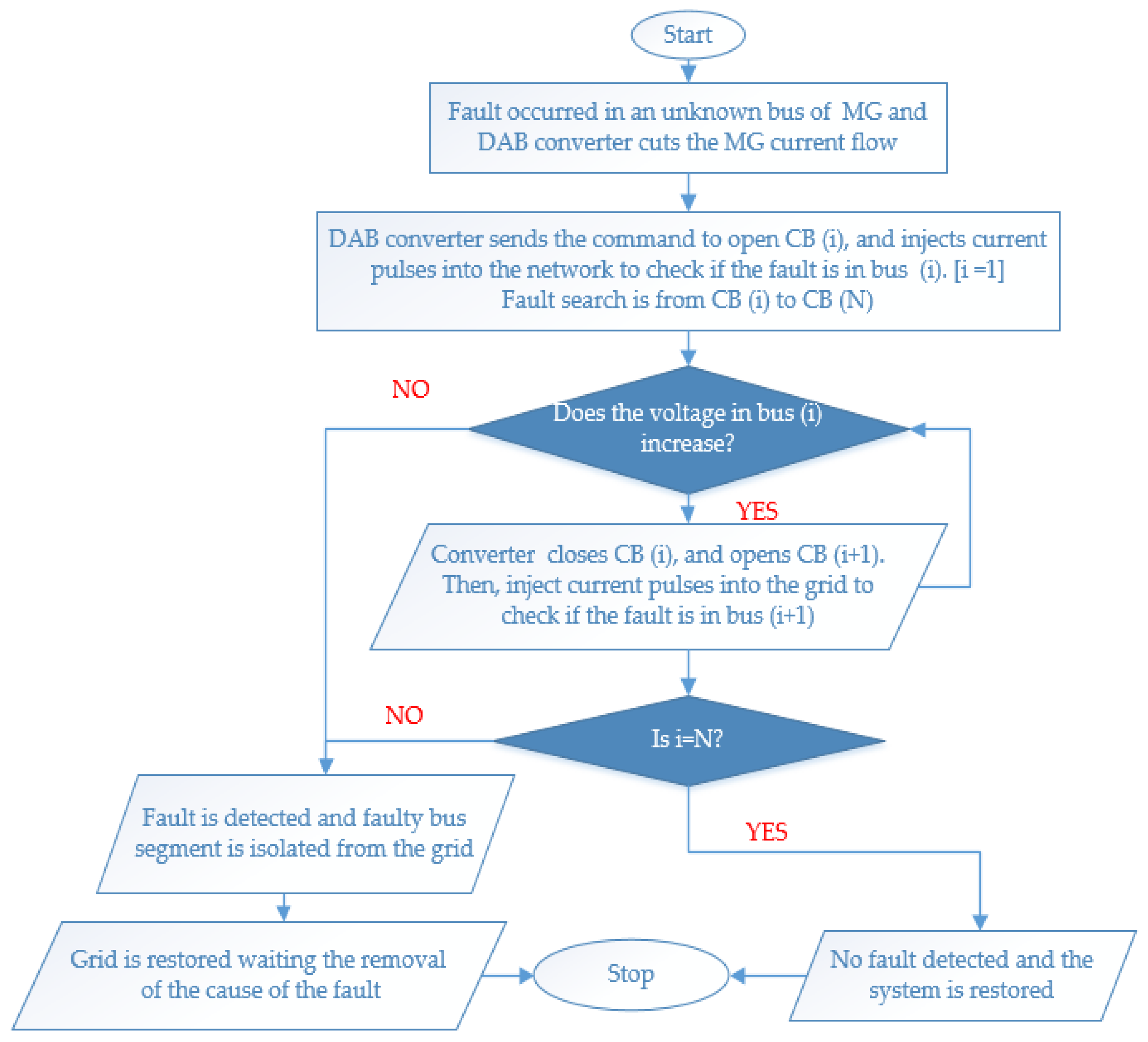
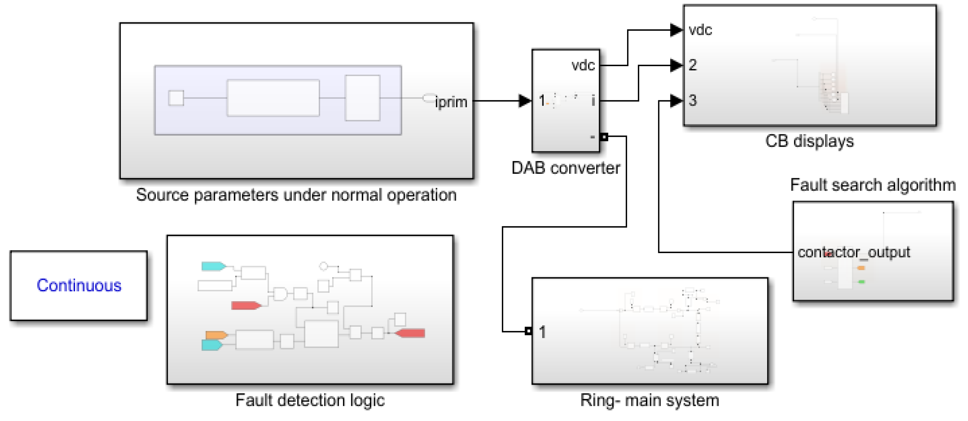
3. Methods and Materials

In this paper, it is assumed that once a fault is detected in any line or bus segment, the PPDs will be enabled to isolate that faulty segment for restoring the grid. The fault detection and its isolation in the LVDC microgrid were accomplished through the implementation of the algorithms and simulated into the SIMULINK platform in the interval of 1.4 s. In this paper, two methods named bus fault search and line fault search for fault detection and isolation were proposed and analysed; refer to the flowcharts from Figure 5 and Figure 6, respectively. Both methods were based on the voltage measurement, where a faulty segment of the grid would be identified and the decision of the fault location is taken by looking at the sudden increase in current and drop compared with the rated threshold values of current and voltage simultaneously. The voltage characteristics are provided after the DAB converter injects the pulses of the current into the grid for testing if the fault is in a specific grid segment using the two methods shown in Figure 5 and Figure 6. The first method, named bus fault search, relied on the voltage measurement through each CB bus where a faulty bus segment would be identified and isolated from the healthy remaining bus segments. After isolating the faulty segment, the next step was to re-energise the grid and bring back the customers into electricity comfort, as shown in the algorithm in Figure 5. From this method, once a fault has occurred at any unknown grid bus, the DAB converter sends the current signal into the grid relays to open the CBs where there is no more current flow in the network. To start fault searching, the DAB converter sends the current signals in the grid for tripping the bus (CB1), and then the bus voltage is measured. Once the bus voltage is increased, it means that there is no fault detected. However, once this measured voltage is not increased i.e., almost zero, the fault is detected and the fault bus segment is isolated from the network followed by the grid restoration.
The difference between this method with the first one is that the fault is occurring at any grid line, and the technique for detecting the fault is based on the line voltage measurement across the two line relays of both ends of the tested line. Here, a fault is detected once the measured line voltage is not increasing or equivalent to zero by following the steps shown in Figure 6. In both methods, it is assumed that during normal operation, the current and voltage are constantly working at rated threshold values. Under the fault condition, the protective relays will detect and isolate faulty line segments for ensuring the normal operation of the remaining healthy line segments. For simplifications during design and simulation, it was assumed that the DAB converter represents the power source in the considered DCMG network. Thus, the converter nominal voltage at its high voltage side (HVS) under normal operating conditions (Vth) was 200 V, while the converter rated current at its high voltage side (HVS) under normal conditions (Ith) was 5 A as shown in Table 1. These threshold values were considered as the output from the HVS of the DC-DC converter, where the rated values from the grid source were discussed by the authors in [19], and this converter acts as the interface between the grid DES (at its LVS) and the load (at its HVS).
In both used methods, both line voltage (VLine) and bus voltage (Vbus) are compared with the rated threshold voltage (Vth) as shown in equation (2). Under normal operating conditions, these three voltages are of the same values and during the fault, VLine and Vbus become less than Vth. Consequently, VLine and Vbus decrease and collapse to zero. This is associated with the sudden increase in line current for a short moment, where also it drops to zero. During this research, the system components and their ratings are presented in Table 1, where the types of used power cables are found in [43].
VLine (Vbus) < Vth
In this work, the proposed system protections with fault detection, identification, and isolation are constructed through SIMULINK/MATLAB as shown in Figure 7 with a ring-main system. In this model, the threshold values of voltages are compared with simulated values in the whole interval from 0 to 1.4 s. From this model, the faulty segment was detected and isolated from the healthy grid network, where the voltage and current values under normal operating conditions are compared with those under fault conditions. At this time, the block diagrams of the network between the DER source, DAB converter, and fault detection logic in a ring-main system with the CBs display were shown.

4. Results and Discussion

The proposed fault detecting and isolating methods employed in DCMG systems are analysed in this section. Here, the tripping devices (i.e., protective relays) could reliably trip within microseconds for limiting the effects of the fault in the network. In this work, the ring-main system is fragmented into line sections and each section is monitored by a DAB converter which is used to send the current signal to the relays (located at each bus) for opening or closing the corresponding grid CBs. Once a fault is detected, the relay receives a command from the DAB converter for opening its assigned CB of the corresponding line as presented in Figure 8, and these CBs could be automatically closed once there is no fault detected or when the faulty section is isolated from the network.
During this case refer to Figure 8, where the fault is detected in L-1 at 0.5 s; the corresponding relay is acting in the way that the CBs of the faulty line would open and de-energise the fault segment. If the faulty section is successfully de-energised, the relay attempts to send a command for reclosing the protective relays for restoring the faulty section but it fails, and the reclosing will be achieved once the cause of the fault is removed.
Once fault checking is complete without fault recognition (the same case as normal grid operation), all grid relays are switched-on as shown in Figure 9; for ensuring the current flow in both directions refer to Figure 4. Once a short-circuit fault is detected in any part of the grid (see at 0.5 s in Figure 8), all CBs are tripped to cut off their respective current flow in the specified faulty section of the MG. This is accomplished in a short period to avoid the MG structures becoming damaged, and so that customers do not lose electricity comfort for a long time. Figure 8 shows the position of two CBs in the segment under fault, while Figure 9 shows the positions of two CBs under normal operation.

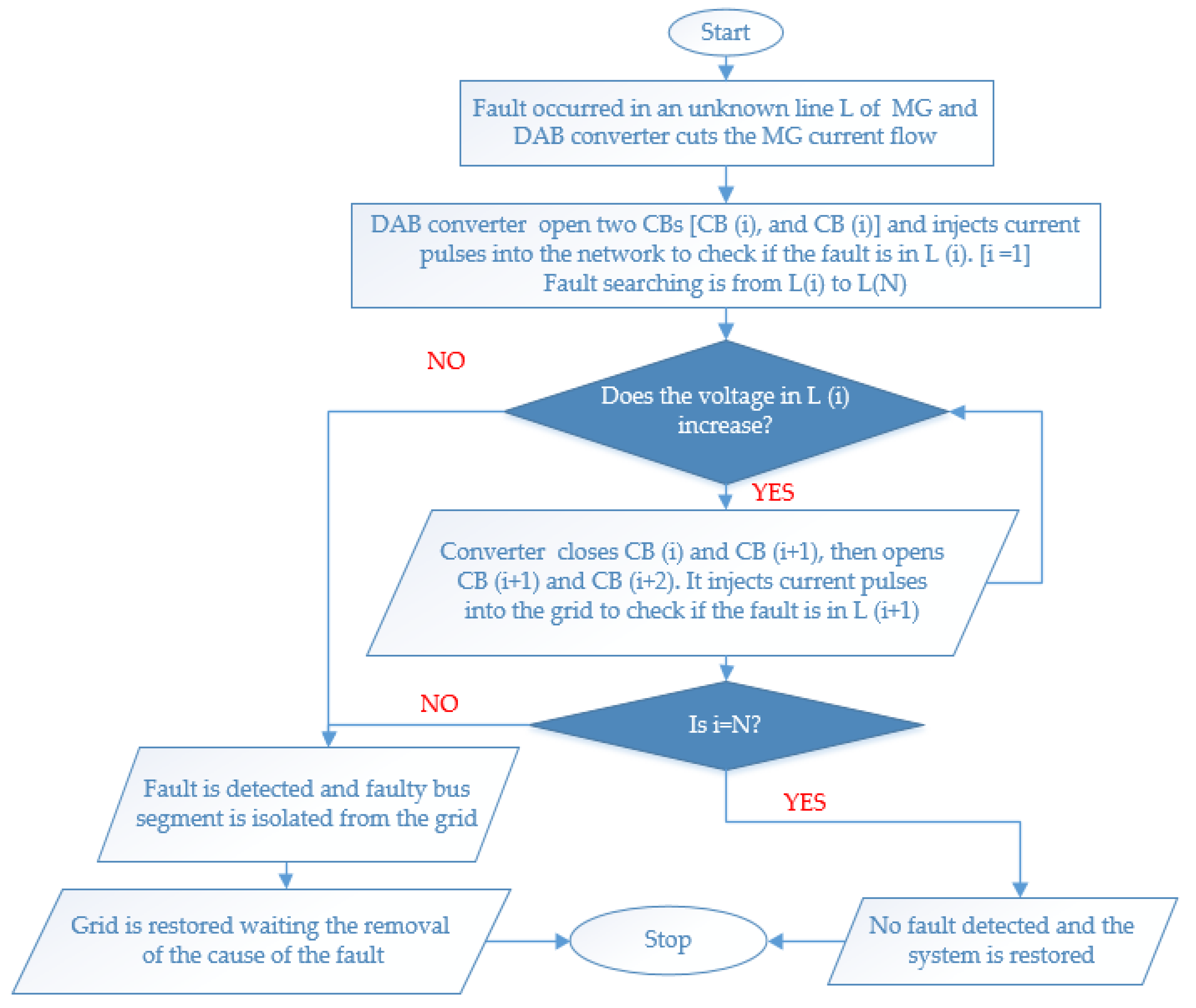
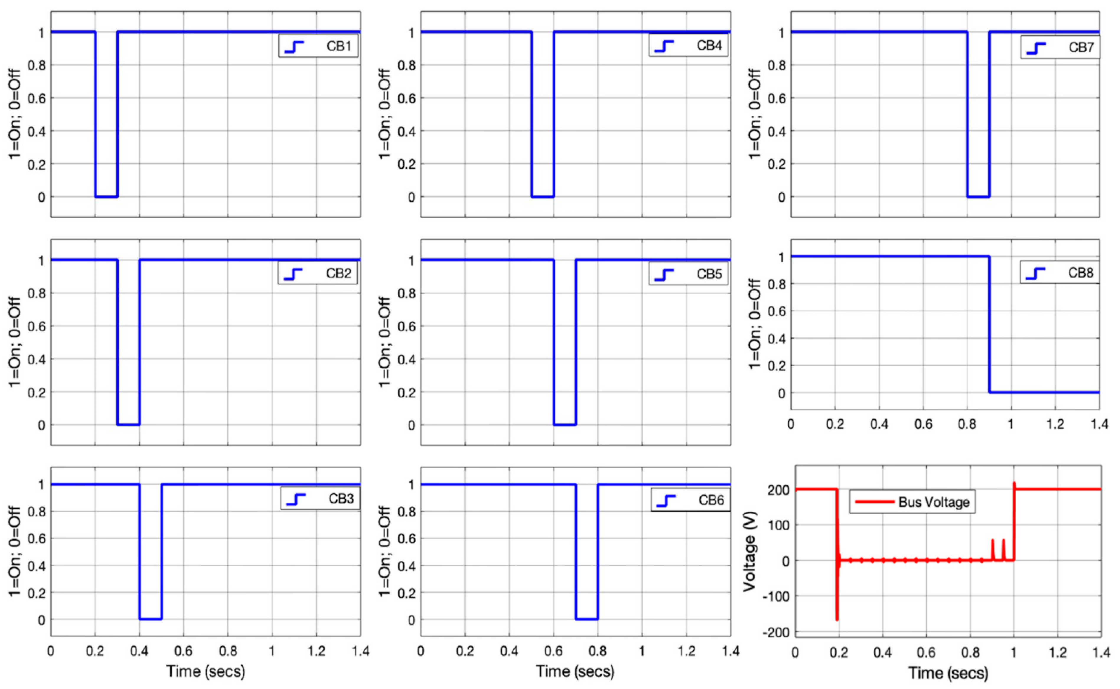
4.1. Bus Fault Searching by Operating Individual CBs in the Microgrid

The simulation results in this section were obtained following the methodology from the flowchart in Figure 5. Quick fault detection and the isolation of the faulty part of the LVDC microgrid are necessary for keeping the grid customers in electricity comfort, and the grid remains safely protected. Therefore, possible technologies and methods could be applied for reaching the above goals. In this paper, the first proposed method was to search for where the fault was occurring by considering each bus in the network. Referring to Figure 10, it can be seen that during normal operation, the rated current continues to flow without any blackout and variations as this current was injected from the DC-DC or (DAB) converter HVS. In this study, the threshold values of the currents and voltages when the MG is under normal operation are shown in Table 1. Initially, refer to Figure 10 during normal operating conditions (from 0 to 0.175 s.), no fault was detected and both current and the voltage are at their threshold rated values. When a fault is detected, the voltage is suddenly dropped to zero, while the current is transiently increased to its higher value and then dropped to zero. Therefore, the fault searching is started by opening the bus-1 using CB1 and letting the DAB converter inject pulses of current into the grid to see if the fault is there and continue to do so for CB2, CB3 up to the last CB.
Here, when the fault is detected it refers to the voltage characteristics when there is no voltage increase (remains at 0 V) as discussed in Section 3. If the fault is detected, the relay will isolate the faulty bus segment from the healthy network and the DAB converter activates/closes all relays of the healthy part for restoring the grid network. It is observed that the fault is detected the bus-8, where this faulty bus is isolated (remains at 0). It is clear that during the fault searching when the fault is detected (from 0.2 to 1 s), the measured voltage value is zero (0 v), i.e., less than the threshold value of 200V as indicated by Equation (2). Once the faulty bus segment is isolated, the grid is restored and the customers are back into electricity comfort, as shown after 1 second. The advantage of using this method is that the fault can be detected once it is occurring at any grid part, but it suffers from a long time that it could take to detect the fault and isolate the faulty part of the MG because each grid bus must be checked.

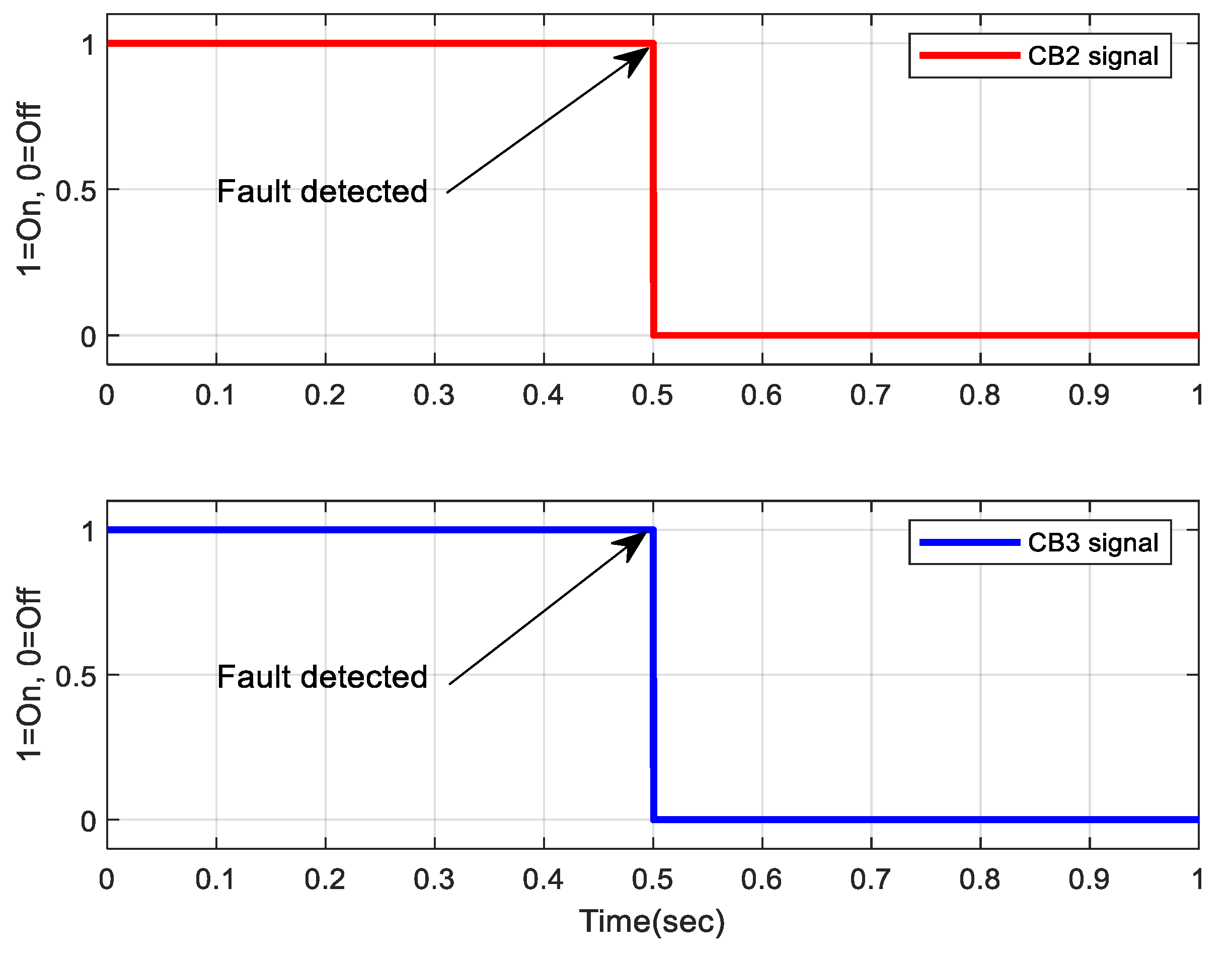
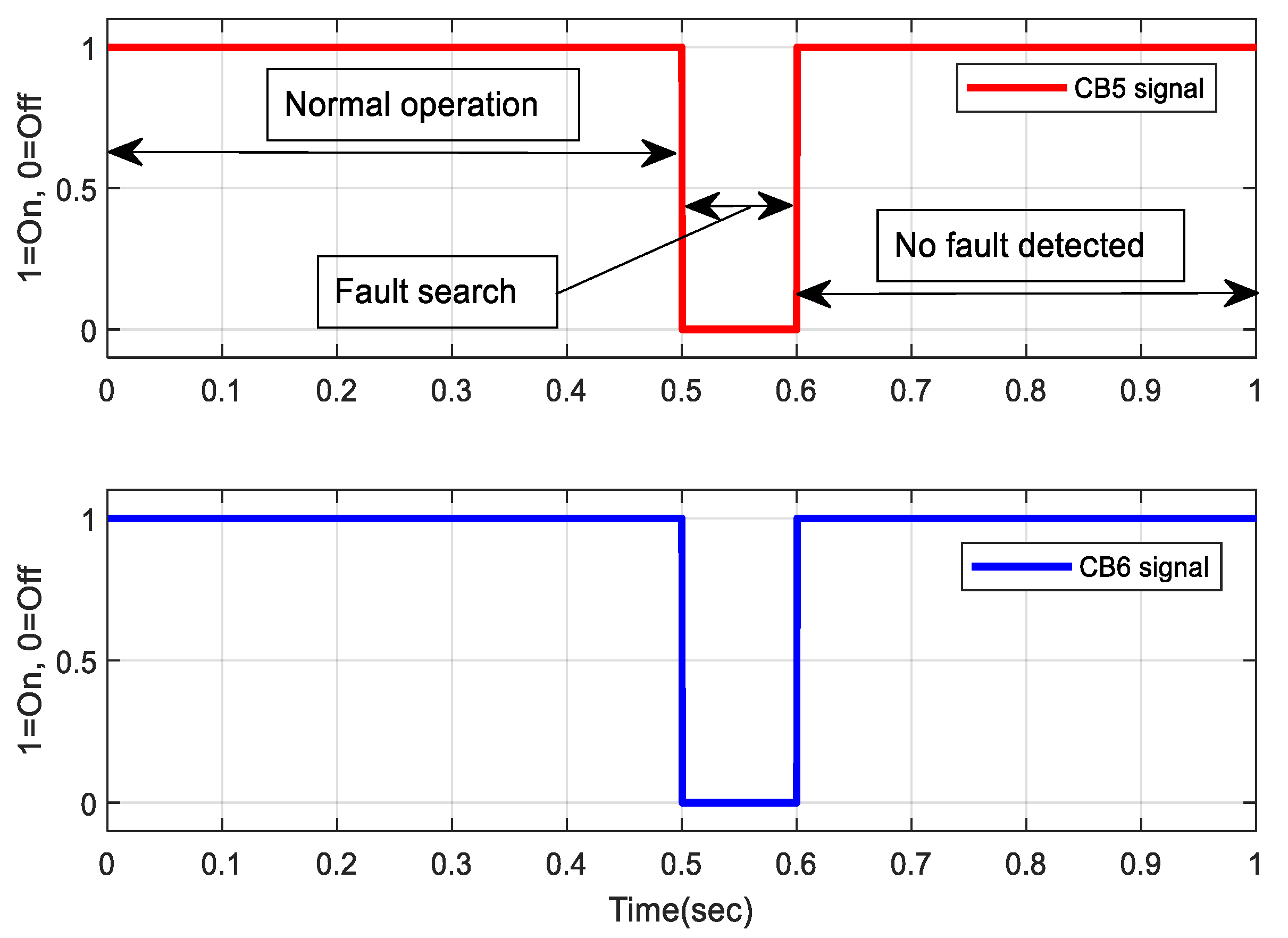
4.2. Line Fault Searching through the Two Nearby CBs across a Line

The simulation results in this subsection were obtained following the methods from the flowchart in Figure 6. This paper proposed an improved scheme for detecting the fault and isolating the faulty section in any DCMG network compared to the previous one (bus fault searching) because it takes a short duration to check all CBs in the grid lines. Here, the fault searching is achieved by opening the two grid relays located on both sides of a grid line (for example CB2 and CB3 for Line-1) in Figure 4, where the remaining relays of other lines will remain closed.
To detect the faulty segment, here the DAB converter also sends the current pulses into the grid as completed in Section 4.1. As shown in Figure 11, the fault is detected at L-3, and the two relays around this line open and isolate this faulty line segment, and the DAB converter activates all relays in the remaining healthy grid part followed by the grid re-energisation and the customers are back in electricity comfort in a short time after the fault occurrence. The simulation results show that during normal operation (pre-fault and post-fault conditions), the fault current is ideally zero as shown in Figure 11 from 0.2 to 0.5 s. When the fault is detected at 0.175 s, the current is suddenly increased to 20 times the rated value of the current, and at 0.2 s the current is dropped to zero; then the next step is to search for where the fault is located. As observed in Figure 11, the fault search starts by opening the two relays in the first line (CB1 and CB2), and then the current is injected into this line. As observed, the fault is not detected there and those relays are closed, then the fault search continues to the next line where CB3 and CB4 are opened. Despite the fault occurrence, it can be observed that the normal current would continuously flow for a short time (0.175 to 0.2 s) from the DAB converter to the grid network due to the load-side discharge capacitor because of the fault current blocking conditions. The advantage of this method is related to the short time it would take for detecting the fault and isolating the faulty segment of the MG compared to the bus fault search method, and this method is recommended to be applied to the LVDC microgrid networks. The choice of this method is also linked to the reduction in the PPDs because one relay can be used to monitor the status of two CBs around a power line. From Figure 11 it is observed that in 0.5 s the fault is detected, the faulty section is removed from the grid, and simultaneously the grid is restored, which is one of the advantages of using this method.

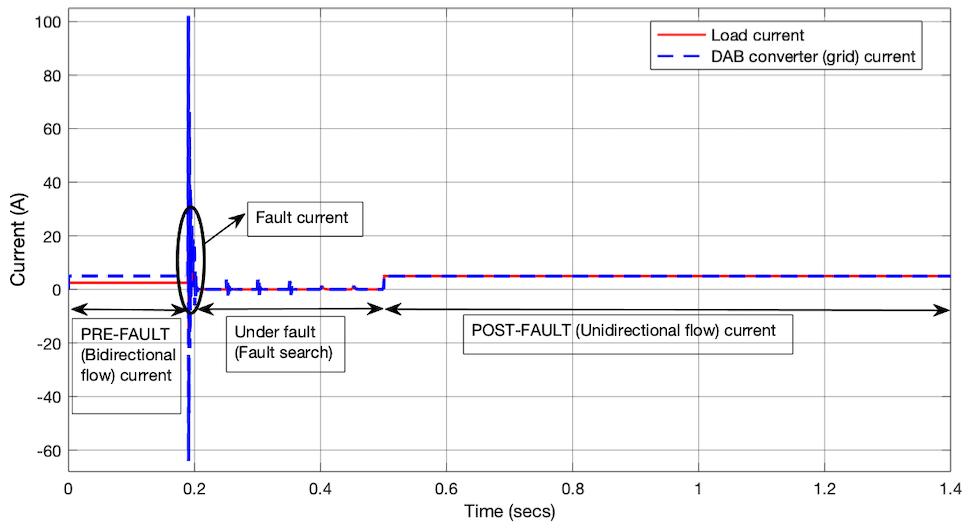
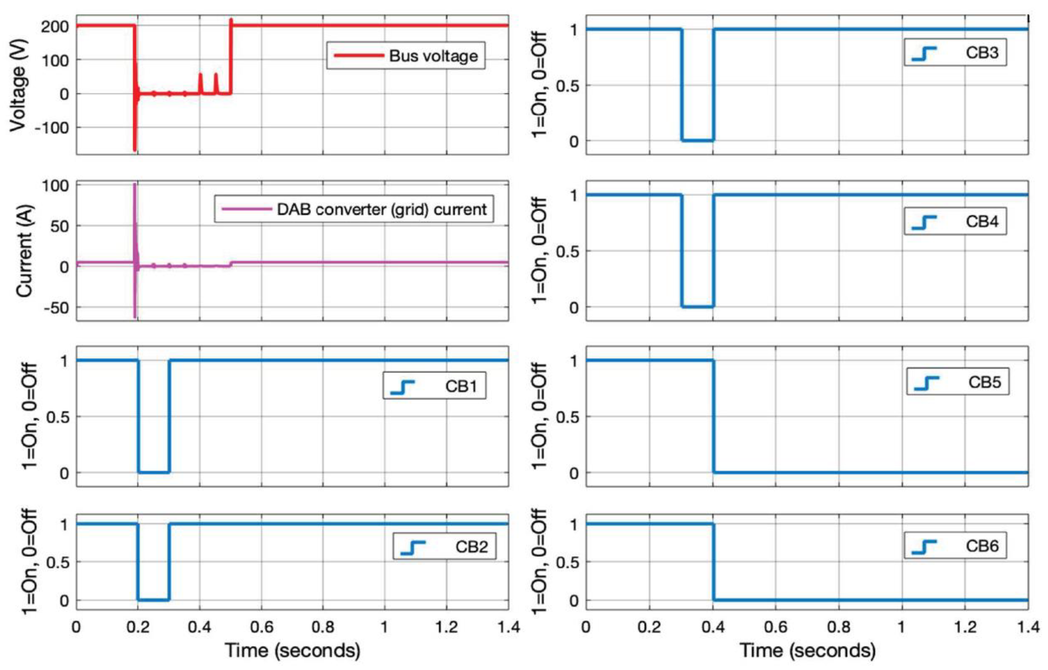
4.3. Analysis of Current under Normal and Fault Conditions

Fault current analysis in the DCMG network is crucial during the design of a suitable protection scheme. The rapid increase in the initial transient DC fault current in a short time of fault occurrence [31], as shown in both Figure 12 and Figure 13 (from 0.175 to 0.2 s), exposes the grid system to a high thermal and mechanical stress. For avoiding the grid equipment damage, the fault clearance through the PPDs could be completed in a short scheduled period. Thus, the DCCBs could be capable of resisting the high fault current. Load current and grid current are affected by the fault occurrence in the DC ring-main distribution networks. It was observed that DCMD systems have a high rate of fault current rise compared to ACMG systems due to the availability of DC capacitors in the output DAB converters which discharge over a cable of low values of impedance parameters. This is also associated with a slow decaying of the fault current resulting from the discharge of the grid inductors. Figure 12 and Figure 13 show these current characteristics during the normal operation (with a bidirectional current flow from 0 to 0.175 s), fault searching, and after grid re-energisation (unidirectional current flow). During the normal operation, the grid current of 5 A is injected into the ring-main DCMG network and is subdivided into two directions with 2.5 A on each side (Ic1 and Ic2) as a result of bidirectional current flow during the pre-fault condition (under normal operation).
As explained in Section 3, a fault current would rise to hundreds referring to its rated value as shown in Figure 12 between 0.175 and 0.02 s. Under fault conditions, after short variation followed by the voltage and current are dropping to zero, the next step is to quickly identify the faulty segment and isolate it. The current pulses available from 0.2 to 0.5 s are due to the relay opening, injecting the current and closing that CB relay, means that no fault is detected. In this condition, the purpose of sustaining the grid customers’ electricity was achieved first by identifying (or locating) and isolating the faulty bus or line in the shortest time. Once the fault occurs at 0.175 s, as shown in Figure 12, the tripping signals were sent to the CB for isolating the faulty line using the method developed in Section 3. After fault line searching, this fault was localised at 0.5 s, then the fault line was isolated. After isolating the faulty line (from 0.5 to 1.4 s), the grid was re-energised, which results in a unidirectional current flow as the ring-main system was converted into a radial distribution system, where one current direction is cut. Consequently, the DAB converter current became the same as that of the load (load current was changed from 2.5 to 5 A) as shown in Figure 12. Therefore, the whole current from the DAB converter would be the same as that of the loads in the remaining healthy part after isolating the faulty part of the LVDC microgrid. Figure 13 shows the fault current characteristics from 0 to 1.4 s. It was shown that the fault current was zero during normal operating conditions and when there was an isolation of the fault in the grid. This current started appearing from 0.175 to 0.2 s when the fault suddenly appeared in the MG, and the level of this current depended on the fault type and its cause.
It was observed that once the fault was detected and isolated from the grid, this current remained at zero position i.e no fault current detected. Mostly, the proposed LVDC protection scheme consisted of detecting the fault current in the line and bus segments of a DCMG system. Looking at both Figure 12 and Figure 13, it was observed that the fault current became 20 times the threshold value, and the methods for isolating a faulty segment were discussed for avoiding the whole grid system blackout for a long time, which results in the customers’ loss of electricity comfort. In practice, an inductor is needed to be inserted into the output filters of the DAB converters for reducing the above high current fault.

5. Conclusions

In this paper, the methods for detecting the fault and isolating the faulty segment in the low voltage DCMG system were discussed. The simulation results showed that the faulty part of the network could precisely and quickly be identified and isolated from the entire network, resulting in the grid restoration allowing the customers of the remaining unfaulty part to continue to receive electricity. From the proposed methods, the line fault searching method was recommended for detecting the fault and isolating it from the grid as it took a short amount of time to restore that grid after isolation of the faulty segment, which improved the grid performance. Moreover, it was seen that the design and simulation of the said method could reduce the time taken to detect the fault, requiring relays inserted at both ends of the grid line for communicating with the DAB converter. It can be concluded that the proposed scheme for grid protection may be applied in different DCMG systems in remote villages.

Author Contributions

The first author is P.H. Other authors have contributed as follows: conceptualisation, A.J.F. and J.M.R.B.; methodology, A.J.F.; software, J.M.R.B.; validation, A.J.F. and J.M.R.B.; formal analysis, A.J.F.; writing—original draft preparation, P.H.; writing—review and editing, A.J.F. and J.M.R.B.; visualisation, A.J.F. and J.M.R.B.; supervision, A.J.F., E.N. and J.M.R.B.; project administration, E.N.; funding acquisition, A.J.F. All authors have read and agreed to the published version of the manuscript.

Funding

This work was supported by the GCRF fund through the Engineering and Physical Sciences Research Council UK (EPSRC) under project RENGA (EP/R030235/1). It was also funded by the African Center of Excellence in Energy for Sustainable Development (ACE-ESD) under the University of Rwanda, College of Science and Technology (UR-CST).

Acknowledgments

The authors of this paper would like to acknowledge the Engineering and Physics Sciences Research Council (UK) as part of the Resilient Electricity Networks for a productive Grid Architecture (RENGA) project based at the Imperial College of London (UK) for the support to this for this work. The authors also acknowledge the African Center of Excellence in Energy for Sustainable Development under the University of Rwanda, College of Science and Technology.

Conflicts of Interest

The authors declare no conflict of interest.

Nomenclatures

CBCircuit breaker
DAB DualActive bidirectional (converter)
PPDPower protective devices
ZCPZero-crossing point
ICM MainCurrent (from DAB converter)
IC1Current in direction-1
IC2Current in direction-2
VLineLine voltage
VbusBus voltage
VthThreshold voltage
IthThreshold current
LVDCLow-voltage direct current
MGMicrogrid
RENGAResilient Electricity Networks for a productive Grid Architecture

References

  1. He, J.; Chen, K.; Li, M.; Luo, Y.; Liang, C.; Xu, Y. Review of protection and fault handling for a flexible DC grid. Prot. Control Mod. Power Syst. 2020, 5, 15. [Google Scholar] [CrossRef]
  2. Lin, Z.; Nengling, T.I.; Wentao, H.; Jian, L.; Yanhong, W. A review on protection of DC microgrids. J. Mod. Power Syst. Clean Energy 2018, 6, 1113–1127. [Google Scholar] [CrossRef] [Green Version]
  3. Thi, T.H.M. Evaluation of DC Supply Protection for Efficient Energy Delivery in Low Voltage Applications. Ph.D. Thesis, Universite de Lyon, Lyon, France, 2018. [Google Scholar]
  4. Wei-Chen, L.; Wei-Tzer, H.; Kai-Chao, Y.; Hong-Ting, C.; Chun-Chiang, M. Fault Location and Restoration of Microgrids via Particle Swarm Optimization. Appl. Sci. 2021, 11, 7036. [Google Scholar] [CrossRef]
  5. Sonia, M.; Manel, J.B.G.; Jihen, A.Z.; Ilhem, S.B. Residual-Based Fault Detection and Isolation in LVDC Microgrid; Elsevier Inc.: New York, NY, USA, 2022; pp. 1–24. [Google Scholar] [CrossRef]
  6. Siavash, B.; Robert, M.C.; Mojtaba, F.; Mehdi, S.; Guerrero, J.M. DC Microgrid protection: A Comprehensive Review. IEEE J. Emerg. Sel. Top. Power Electron. 2019, 21, 1–25. [Google Scholar] [CrossRef]
  7. Yadav, N.; Tummuru, N.R. A Real-Time Resistance Based Fault Detection Technique for Zonal Type Low-Voltage DC Microgrid Applications. IEEE Trans. Ind. Appl. 2020, 56, 6815–6824. [Google Scholar] [CrossRef]
  8. Sheikh, A.A.; Wakode, S.A.R.; Deshmukh, R.; Ballal, M.S. A Protection Scheme for Fault Detection, Location and Isolation in DC Ring Microgrid. In Proceedings of the IECON 2019—45th Annual Conference of the IEEE Industrial Electronics Society, Lisbon, Portugal, 14–17 October 2019. [Google Scholar] [CrossRef]
  9. Sijo, A.; Jimmy, E.Q.; Matthew, J.R.; Sukumar, B. DC Microgrid Protection: Review and Challenges; Technical Report for Sandia National Laboratories: Albuquerque, NM, USA, 2018. [Google Scholar] [CrossRef]
  10. Meenakshisundaram, R.; Sivasakthi, S.; Vignesh, M. DC Ring-Bus Microgrid Fault Protection and Identification of Fault Location. Int. J. Technol. Res. Eng. 2015, 2, 2347–4718. [Google Scholar]
  11. Rajeev, K.C.; Kalpana, C. Smart protection system for identification and localisation of faults in multi-terminal DC microgrid. IET Smart Grid 2020, 3, 882–889. [Google Scholar] [CrossRef]
  12. Sohrab, M.; Xinzhou, D.; Shenxing, S.; Dimitrios, T. Challenges, Advances and Future Directions in Protection of Hybrid AC/DC Microgrids. IET Renew. Power Gener. 2017, 10, 79. [Google Scholar] [CrossRef] [Green Version]
  13. Behrooz, T.; Seyed, A.H. Detection of High Impedance Fault in DC Microgrid Using Impedance Prediction Technique. In Proceedings of the 15th International Conference on Protection and Automation of Power Systems (IPAPS), Shiraz, Iran, 30–31 January 2021; pp. 1–8. [Google Scholar]
  14. Nikhil, K.S.; Ruturaj, P.; Samantaray, S.R.; Bhende, C.N. A Fast Fault Detection Scheme for Low Voltage DC Microgrid. In Proceedings of the 21st National Power Systems Conference (NPSC), Gandhinagar, India, 29 January 2021; pp. 1–7. [Google Scholar] [CrossRef]
  15. Waqas, J.; Dong, C.; Mohamed, E.F.; Yan, X. System Configuration, Fault Detection, Location, Isolation and Restoration: A Review on LVDC Microgrid Protections. Energies 2019, 12, 1001. [Google Scholar] [CrossRef] [Green Version]
  16. Sumanth; Akash, S.; Sangeeta, M. Fault Analysis and Protection of DC Microgrid. Int. J. Eng. Res. Technol. IJERT 2020, 8, 122–126. [Google Scholar]
  17. Liang, K.; Heng, N. Transient Modeling Method for Faulty DC Microgrid Considering Control Effect of DC/AC and DC/DC Converters. IEEE Access 2020, 8, 150759–150772. [Google Scholar] [CrossRef]
  18. Deshmukh, R.R.; Ballal, M.S.; Suryawanshi, H.M.; Mishra, M.K. An Adaptive Approach for Effective Power Management in DC Microgrid Based on Virtual Generation in Distributed Energy Sources. IEEE Trans. Ind. Inform. 2020, 16, 362–372. [Google Scholar] [CrossRef]
  19. Hategekimana, P.; Rodriguez-Bernuz, J.M.; Junyent-Ferre, A.; Ntagwirumugara, E. Assessment of Feasible DC Microgrid Network Topologies for Rural Electrification in Rwanda: Studying the Kagoma Village. In Proceedings of the 2020 International Conference on Smart Grids and Energy Systems (SGES), Perth, Australia, 23–26 November 2020; pp. 854–859. [Google Scholar] [CrossRef]
  20. Chetan, S.; Manoj, T. DC microgrid protection issues and schemes: A critical review. Renew. Sustain. Energy Rev. 2021, 151, 111546. [Google Scholar] [CrossRef]
  21. Gururajapathy, S.S.; Mokhlis, H.; Illias, H.A. Fault Location and Detection Techniques in Power Distribution Systems with Distributed Generation: A Review; Elsevier: Berlin, Germany, 2017; Volume 74, pp. 949–958. [Google Scholar] [CrossRef]
  22. Ming, Y.; Wang, Y.; Zhang, L.; Ziguang, Z. DC short circuit fault analysis and protection of ring type DC microgrid. In Proceedings of the IEEE 8th International Power Electronics and Motion Control Conference (IPEMC-ECCE Asia), Hefei, China, 22–26 May 2016; pp. 1694–1700. [Google Scholar] [CrossRef]
  23. Anselmo, I.S.; Rashid, M.H. Solid-State Circuit Breakers for D.C. Microgrid Applications. In Proceedings of the International Conference on Electrical, Communication, and Computer Engineering (ICECCE), Istanbul, Turkey, 12–13 June 2020; pp. 1–4. [Google Scholar] [CrossRef]
  24. Pate, P.; Kamal, S.; Pate, P. New Scheme of Protection for LVDC Bus Microgrid System. Cikitusi J. Multidiscip. Res. 2018, 7, 53–60. [Google Scholar]
  25. Ibrahim, A.; Marwan, A. Fault Diagnosis Based Approach to Protecting DC Microgrid Using Machine Learning Technique. Procedia Comput. Sci. 2017, 114, 449–456. [Google Scholar] [CrossRef]
  26. Mohammad, A.; Yaqobi, H.M.; Mir, S.S.D.; Mohammed, E.L.; Abdul, M.H.; Senjyu, T. Low-Voltage Solid-State DC Breaker for Fault Protection Applications in Isolated DC Microgrid Cluster. Appl. Sci. 2019, 9, 723. [Google Scholar] [CrossRef] [Green Version]
  27. Noor, H.; Mashood, N.; Juan, C.V.; Guerrero, J.M. Recent Developments and Challenges on AC Microgrids Fault Detection and Protection Systems–A Review. Energies 2020, 13, 2149. [Google Scholar] [CrossRef]
  28. Wu, P.; Huang, W.; Tai, N.; Liang, S. A novel design of architecture and control for multiple microgrids with hybrid AC/DC connection. Appl. Energy 2018, 74, 1002–1016. [Google Scholar] [CrossRef]
  29. Sharthak, M.; Juan, C.B. Short-Circuit Protection for Low-Voltage DC Microgrids Based on Solid-State Circuit Breakers. In Proceedings of the IEEE IEEE 7th International Symposium on Power Electronics for Distributed Generation Systems (PEDG), Vancouver, BC, Canada, 27–30 June 2016. [Google Scholar] [CrossRef]
  30. Dionne, S.; Mike, S.; Harsha, R.; Mischa, S. Advances to megawatt scale demonstrations of high speed fault clearing and power restoration in breakerless MVDC shipboard power systems. In Proceedings of the IEEE Electric Ship Technologies Symposium (ESTS), Arlington, VA, USA, 14–17 August 2017; pp. 312–315. [Google Scholar] [CrossRef]
  31. Ankan, C.; Singh, G.K.; Vinay, P. Protection techniques for DC microgrid—A review. Electr. Power Syst. Res. 2020, 187, 106439. [Google Scholar] [CrossRef]
  32. Sheikh, A.A.; Wakode, S.A.; Deshmukh, R.R.; Ballal, M.S.; Suryawanshi, H.M.; Mishra, M.K.; Kumar, S. A Brief Review on DC Microgrid Protection. In Proceedings of the 2020 IEEE First International Conference on Smart Technologies for Power, Energy and Control (STPEC), Nagpur, India, 25–26 September 2020; pp. 1–7. [Google Scholar] [CrossRef]
  33. Anju, M.; Saikat, C.; Srivastava, S.C. An On-line Fault Location Technique for DC Microgrid Using Transient Measurements. In Proceedings of the 7th International Conference on Power Systems (ICPS), Pune, India, 21–23 December 2017; pp. 386–391. [Google Scholar] [CrossRef]
  34. Bayati, N.; Baghaee, H.R.; Hajizadeh, A.; Soltani, M.; Lin, Z.; Savaghebi, M. Local Fault Location in Meshed DC Microgrids based on Parameter Estimation Technique. IEEE Syst. J. 2021, 16, 1606–1615. [Google Scholar] [CrossRef]
  35. Anju, M.; Suresh, C.S.; Saikat, C. Local measurement-based technique for estimating fault location in multi-source DC microgrids. IET Gener. Transm. Distrib. 2018, 12, 3305–3313. [Google Scholar] [CrossRef]
  36. Sangit, S.; Abhinav, B.; Elangovan, D.; Arunkumar, G. DC Microgrid System for Rural Electrification. In Proceedings of the International Conference on Energy, Communication, Data Analytics and Soft Computing (ICECDS), Chennai, India, 1–2 August 2017; pp. 307–317. [Google Scholar]
  37. Vinogradov, A.; Vinogradova, A.; Bolshev, V. Analysis of the Major Constituents of the Power Supply System Efficiency for Rural Consumers. IETE J. Res. 2020, 17, 1–10. [Google Scholar] [CrossRef]
  38. Luis, E.Z. Are Microgrids the Future of Energy? DC microgrids from concept to demonstration to deployment. EE Electrif. Mag. 2016, 14, 37–44. [Google Scholar] [CrossRef]
  39. Vinny, M.; Pitshou, N.B.; Moses, O.O. A Review of Microgrid-Based Approach to Rural Electrification in South Africa: Architecture and Policy Framework. Energies 2020, 13, 2193. [Google Scholar] [CrossRef]
  40. Chengwei, L.; Rodriguez-Bernuz, J.M.; Junyent-Ferre, A. A low-cost and efficient fault detection and location algorithm for LVDC microgrid. In Proceedings of the IEEE 22nd Workshop on Control and Modeling for Power Electronics (COMPEL), Cartagena, Colombia, Online Conference, 2–5 November 2021. [Google Scholar] [CrossRef]
  41. Rodriguez-Bernuz, J.M.; Junyent-Ferré, A.; Xin, X. Optimal Droop Offset Adjustments for Accurate Energy Trading in Rural DC Mini-Grid Clusters. In Proceedings of the 2020 International Conference on Smart Grids and Energy Systems (SGES), Perth, Australia, 23–26 November 2020; pp. 1–6. [Google Scholar] [CrossRef]
  42. Somasekar, K.; Mathumathi, T.; Anand, K. Fault detection in dc microgrid system. Int. J. Adv. Manag. Technol. Eng. Sci. 2017, 7, 245–257. [Google Scholar]
  43. Power Stream Technology. Wire Gauge and Current Limits Including Skin Depth and Strength. 23 April 2021. Available online: https://www.powerstream.com/Wire_Size.htm (accessed on 3 October 2021).
Figure 1. A typical ring-main topology of a DCMG.
Energies 15 04460 g001
Figure 2. Possible fault types in the DCMG system.
Energies 15 04460 g002
Figure 3. Proposed flowchart for protection schemes for a DCMG system.
Energies 15 04460 g003
Figure 4. Proposed DCMG with possible line faults (F-L1, F-L2, and F-L3).
Energies 15 04460 g004
Figure 5. Fault detection using bus fault search by opening and closing individual CBs.
Energies 15 04460 g005
Figure 6. Fault detection using line fault search by opening and closing two nearby CBs.
Energies 15 04460 g006
Figure 7. Simulink model with PI controller for fault detection logic and renewable energy source parameters normal operation controller.
Energies 15 04460 g007
Figure 8. The CB2 and CB3 signals under grid fault occurrence at Line-1.
Energies 15 04460 g008
Figure 9. The CB5 and CB6 of the MG under normal operation, fault searching, and no-fault detected at Line-2.
Energies 15 04460 g009
Figure 10. Bus fault searching by opening and closing each relay in the DCMG with the fault detected at CB8 in 0.9 s, and the faulty part was isolated, then the grid was re-energised.
Energies 15 04460 g010
Figure 11. Line fault searching using a pair of the CBs across each line of the grid, the fault is found in Line-3 (see CB5 and CB6), where the faulty line is isolated and the grid is restored.
Energies 15 04460 g011
Figure 12. DAB converter (or grid) current and load current under normal or pre-fault (bidirectional current flow), fault searching, and after grid re-energisation or post-fault (unidirectional current flow) conditions.
Energies 15 04460 g012
Figure 13. Fault current in the LVDC microgrid during normal operation, during the fault, and when the fault is isolated.
Energies 15 04460 g013
Table 1. Ratings of DCMG components for the study case.
System ComponentRating
Converter nominal voltage at HVS (Vth)200 V
Converter rated current at HVS (Ith)5 A
Rated power1000 W
Frequency of operation 100 kHz
Line resistance0.81508 mΩ/m
Line inductance0.1 mH/m
Length of grid cable500 m
Converter low-voltage side48 V
Converter capacitor50 µF
Publisher’s Note: MDPI stays neutral with regard to jurisdictional claims in published maps and institutional affiliations.

