Abstract
This paper proposes the full simulation model for the electrical analysis of all-electric ship (AES) based on a medium voltage DC power system. The AES has become popular both in the commercial and the military areas due to a low emission, a high fuel consumption efficiency, and a wide applicability. In spite of many advantages, it is complex and difficult to construct the whole system with many mechanical and electrical components onboard. Full electrical analysis is essentially required to simplify the design of the AES, a control and optimization of a ship electric system. The proposed full simulation model of the AES includes the mechanical and the electrical elements by using the MATLAB/Simulink. The mechanical elements are comprised of a steam turbine and a hydrodynamic model of a ship which is adopted by an average value model that is based on the characteristic equation of the mechanical system. The electrical elements are developed by full detailed models which consist of generators, a propulsion motor, a battery, and a power electronics system. In order to design the distribution of the ship, the presented simulation model combined the mechanical and the electrical systems. The consistency of the developed individual models and the integrated AES was verified through the results of the presence or absence of the energy storage system for the speed acceleration and deceleration, loss of prime mover, and full propulsion load rejection.
1. Introduction
The all-electrical ship (AES) is becoming an advanced technology that will dominate the future shipbuilding industry. The conventional ship directly generates a rotating force by a prime mover with a propeller that is connected to a high-speed reduction gear. Hence in the past, the efficiency of the propeller system was a critical factor. However, nowadays, as ships become faster and larger, vibration and noise have become the main problems [1,2,3,4,5]. Unlike conventional propulsion system, the AES is directly applied from a power supply to the high-output propulsion motor. Adopting an electric ship system offers many advantages: space utilization, a reduction of vibration and noise, and reduced fuel consumption of the ship. Furthermore, automation and reliability are increased, which makes the electric propulsion system suitable to reduce labor and the installation of equipment.
Moreover, a medium voltage DC system offers higher energy efficiency by reducing the number of energy conversion steps to feed a large percent of DC loads, higher power density, lower losses, and greater space flexibility. In addition, it is easier to integrate energy storage systems in a DC power system than an AC power system [6,7].
Despite the benefits that are offered by the AES, the electric ship network is infinite, and different from a land electric system. Since the AES operates in various conditions, the electric load and the fluctuation of power consumption change within wide ranges. As such, understanding the interaction between the mechanical and the complex electrical components of the AES is challenging. Also, experimental verification is complicated since the capacity of the ship components is large and complex. A large number of simulation studies have been conducted on the electrical analysis of the AES with a variety of conditions [8,9,10,11,12,13,14]. The papers in [8,9,10,11] have studied transient responses according to the generator output and load regulation of AES. The paper in [12] deals with the effect of variation of AES parameters. The paper in [13] suggests the general design method for AES. The paper in [14] improves the stability of AES using SMES/battery. The paper in [15] proposes the optimal operation strategy under fault conditions. Therefore, this paper proposes a full simulation model for the electrical characteristic analysis of the AES with medium voltage DC system according to the operating conditions and the insertion of the energy storage system.
2. System Configuration and Modeling
Figure 1 shows the full simulation block diagram of the AES. The full simulation model is made with the mechanical and the electrical components that include the power generation system, propulsion system, power electronics system, energy storage system, and power management system, listed in Table 1. The detailed simulation model of the mechanical components and the electrical model are referred to [16,17,18,19,20,21,22,23,24,25,26,27,28,29,30,31,32,33]: the system turbine, the three-phase synchronous generator, the exciter and the governor [16,17,18], the three-phase diode rectifier, the three-phase PM motor, the DC/AC inverter, the DC/DC buck converter, DC/AC inverter and bi-directional DC/DC converter [19,20,21], the hydrodynamic model of the ship [22,23,24], the li-ion battery [25,26,27,28], the ship service load [28,29], the distribution system, and the power management system [30,31,32]. The main DC bus feeds the propulsion motor through a DC/AC PWM inverter. The rated power of the propulsion motor is approximately 90% of the total generation power. Other ship service loads are connected to the secondary low voltage bus through DC/DC converters and a DC/AC inverter. The detailed parameters are referred in the Appendix A.
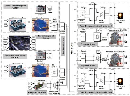
Figure 1.
Full simulation model of the AES implemented in MATLAB/Simulink.

Table 1.
Parameters of the simulation elements.
2.1. Power Generation System
The power generation system serves as an electrical power supply for the AES. It is composed of two steam turbines, two three-phase synchronous generators, two exciter-governors, and two three-phase diode rectifiers.
The steam turbine extracts thermal energy from the pressurized steam. And this steam causes mechanism work on a rotating shaft. [16].
MATLAB/Simulink provides the preset model of the steam turbine which embodies the transfer function of the heat and the flow [16,22,29]. The output torque of the steam turbine Tm can be expressed as Equation (1), where k is the coefficient of the turbine torque and Q is the flow rate.
The three-phase synchronous generator is used by adopting the modified preset model in MATLAB/Simulink. The three-phase diode rectifier is chosen to provide a constant DC voltage. It cannot control the generator output voltage. The voltage is regulated by the excitation system. The excitation system ensures the quality of the generator voltages and the reactive power. The applied excitation system is IEEE standard type of DC1A [17,18].
The governor regulates the fuel injection to control the turbine speed. This is integrated into the power generation system.
Figure 2 shows the waveforms of the simulation results of the power generation system. Figure 2a shows the output power of the propulsion motor which was driven by the ramped reference. According to the demand of the load power, Figure 2b–d shows the output power of the steam turbine, DC bus voltage, and the frequency of the generator, respectively.
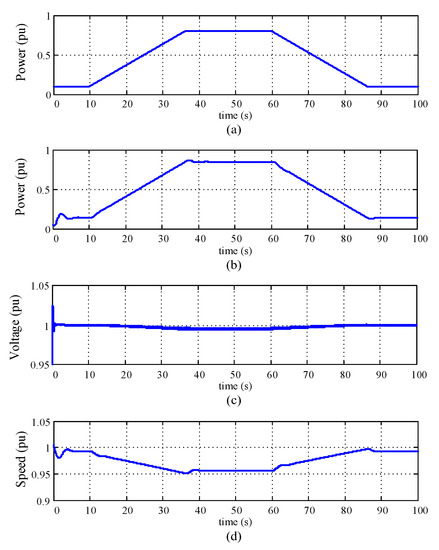
Figure 2.
Simulation results of the power generation system: (a) Output power of the propulsion motor; (b) Output power of the steam turbine; (c) DC bus voltage; and (d) Frequency of the generator.
2.2. Propulsion System
The propulsion system generates the driving force for all-electric ships. It consists of two controllable DC/AC PWM inverters, two propulsion motors, and a ship hydrodynamics model [19,20,21,23]. Various types of propulsion motor have been researched. The propulsion motor adopted the permanent magnet synchronous motor for the simple analysis in this paper. The motor parameters have been modified for the simulation of the MATLAB/Simulink model. The d-q voltages and the torque equations of the propulsion motor are shown in Equation (2), where Rs, Ls, λm, ωr, ωm, Te, TL, Jm, and Bm denote the stator resistance, the stator inductance, the flux density, the rotational angular speed, the mechanical speed, the electric torque, the load torque, the coefficient inertia, and the friction, respectively.
The DC/AC PWM inverter produces the variable output voltage and the frequency for the control of the propulsion motor. Modeling of the propeller can be acquired from the relationships with thrust, torque, and speed. It can be expressed by Equation (3), where is the propeller thrust [N], nm is the propeller shaft speed [rpm], and Qp is the propeller torque [Nm]. The parameters , and KQ are the water density, the propeller diameter, the thrust coefficient, and the torque coefficient, respectively. VA is the advanced velocity of the propeller which is normally less than the ship speed Vs due to the wake of the ocean.
In order to calculate the ship speed from the hydrodynamic model, the ship hydrodynamics model is usually obtained through the experimental results. However, it is impossible to get those data directly. The applied variables of the simulation model that are related to the ship model were acquired indirectly and employed by MATLAB/Simulink Marine system toolbox [22]. Figure 3 shows the simulation results of the propulsion system. Figure 3a–d show the output torque, the motor speed, the output phase currents, and output power of the propulsion, respectively.
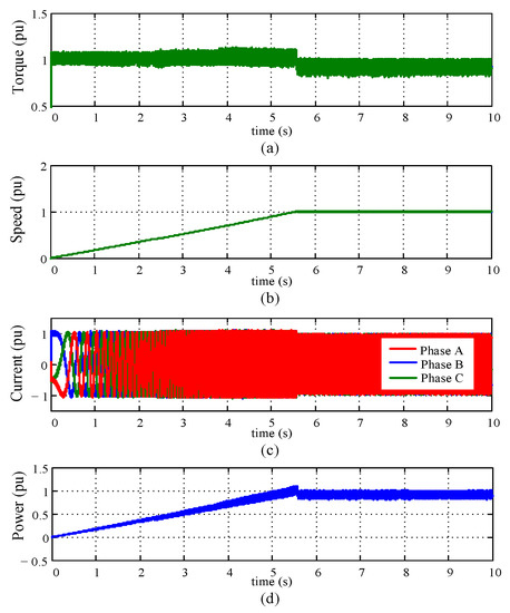
Figure 3.
Simulation results of the propulsion system: (a) Torque of the propulsion motor; (b) Speed of the propulsion motor; (c) Phase currents of the propulsion motor; (d) Output power of the propulsion motor.
2.3. Power Electronics System
The power electronics system consists of three DC/DC converters and two DC/AC inverters for supplying power to the electric loads except the main power of the propulsion motor [19,20,21]. There were two types of DC/DC converters that were simulated for the ship service load and the energy storage system, respectively. Figure 4 shows the simulation results of the DC/DC buck converter for the ship service load. Although the load power is changed, the output voltages of the DC/DC converter and the DC/AC inverter are maintained by the constant power control of the DC/DC converter.
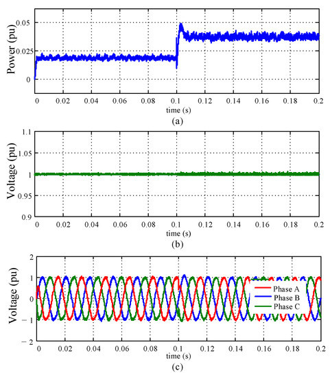
Figure 4.
Simulation results of the power electronics system: (a) Load power; (b) Output voltage of the DC/DC converter; (c) Output voltages of the DC/AC inverter.
2.4. Energy Storage System
The energy storage system is used for the purpose of improving the power quality which is especially affected by a start/stop of the propulsion motor, an abrupt load change and some fault conditions [25,26,27,28,30]. This system is composed of the bidirectional buck/boost DC/DC converter and the Li-ion battery. The capacity of the Li–ion battery is decided from the difference between the output power of the generation capacity and the load power. To verify the operation performance of the modeled energy storage system, the constant charging and discharging currents were both regulated. Figure 5 shows the simulation results of the energy storage system. The charge and discharge current and the battery SOC are shown according to the current reference.
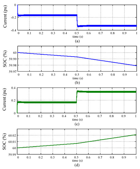
Figure 5.
Simulation results of the energy storage system: (a) Battery discharge current; (b) Battery SOC in case of discharge; (c) Battery charge current; (d) Battery SOC in case of charge.
2.5. Power Management System
Figure 6 shows the configuration of the power management system (PMS), which performs a variety of roles: total ship system control, monitoring, and checking the availability of the electrical power depending on the electrical network status [31,32,33,34,35,36]. The PMS makes it possible to determine the operating status, limit the output power of the propulsion motor, shed the load in accordance with the priorities, control the energy storage system, and detect the system operating mode. Figure 6 suggests a general configuration without designing and reflecting the actual PMS and is modeled to be the background of the simulation results.
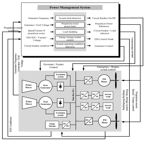
Figure 6.
Configuration of the power management system.
3. Modeling of Integrated Power System
The full simulation model of the AES was combined to obtain the electrical characteristics of the various ship operating conditions. Both voltage and frequency stability are important issues in the power system of the all-electric ship. As such, strict rules need to be established to guarantee secure operation under various operating conditions, such as STANAG 1008, IEC 60092/101, IEEE Std 1709–2010, and MIL Std 1339 [37,38,39,40]. IEEE Std 1709−2010 and STANAG 1008 were used to evaluate the resulting simulation performance. As per IEEE Std 1709−2010, the limitations of the steady state DC voltage tolerances should be within ±10%. Transient state DC voltage can be allowed to have a tolerance of 200% from 0.1 to 10 ms. Frequency stability is referenced with regard to STANAG 1008. This defines the frequency limits for the steady state to be ±3%, and momentary deviations could be allowed to be about ±4%, respectively. A total of three different operating conditions were simulated for the purpose of evaluating the performance of the proposed simulation model. Figure 7 shows three operation conditions of the propulsion motor.
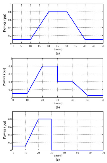
Figure 7.
The operating conditions: (a) Acceleration and deceleration; (b) Loss of prime mover trip; (c) Full propulsion load rejection.
- Acceleration and deceleration (ACC&DEC): Figure 7a shows that the two turbine generators set are initially operating to supply the service load of 10% rated power. Then after 10 s, a 7 %/s acceleration of the propulsion motor is introduced to the system until it reaches to 80% rate power, where it stays for 10 s. Starting from this point, a 7 %/s deceleration is applied to the system, until it finally settles to 10% rated power.
- Loss of prime mover trip (LPMT): 80% of the propulsion power demand is presented in Figure 7b. The circuit breaker for one of the two turbine generators is tripped. The propulsion motors operate at a reduced load, then immediately restored to a power level that is sustainable by the remaining one turbine generator. During this procedure, the turbine generator shall adjust its output power according to the reduced load demand.
- Full propulsion load rejection (FPLR): As shown in Figure 7c, this condition denotes the loss of the full propulsion load. Load rejection is initiated at 30 s with 80% of the propulsion power load. The supply frequency varies directly with the steam turbine speed and frequency because the shaft of the generator is directly coupled to the steam turbine.
4. Simulation Results
Figure 8 shows the simulation results of the acceleration and the deceleration operations. The power of the propulsion motor is initially increasing at a rate of 7%/s. After a steady state at 80%, it starts the decreasing of the rate of 7%/s until the resuming power is at 10% power. Note that the transient DC bus voltage agrees with the IEEE std 1709–2010 voltage tolerance from Figure 8b. Figure 8a,c shows the output power of the propulsion motor and steam turbine, respectively. And Figure 8d shows the pulsation of the frequency which is above the transient state tolerance limit of STANAG 1008.
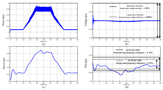
Figure 8.
Simulation results of the acceleration and deceleration (without the energy storage system): (a) Output power of the propulsion motor; (b) Main DC bus voltage; (c) Output power of the steam turbine; (d) Frequency of the generator.
In the case of the trip of one prime mover, Figure 9 shows the simulation results in accordance with IEEE Std 1709–2010 and STANAG 1008. The output power of the propulsion motor is reduced to half due to the control of the power management system to protect the ship electric system. As shown in Figure 9b,d, although the stability of the main DC bus voltage is satisfied, the frequency pulsation during the transient state is increased to about 10%.
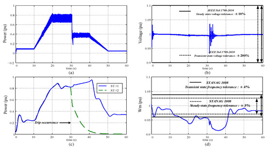
Figure 9.
Simulation results of the loss of prime mover trip (without the energy storage system): (a) Output power of the propulsion motor; (b) Main DC bus voltage; (c) Output power of the steam turbine; (d) Frequency of the generator.
Figure 10 shows the simulation results of the full propulsion load rejection. The turbine generator set supplies the propulsion motor at 80% power, then the circuit breaker of the propulsion motor is open for the purpose of the trip operation. As shown in Figure 10, after the full propulsion load is removed from the electrical distribution system of the ship, the DC bus voltage rises to 1.1 times higher than the rated voltage but it is tolerable by the IEEE Std 1709–2010. However, as shown in Figure 10d, the generator frequency exceeds over approximately 35% and remains around there for about 25 s, which are not tolerable by the IEEE std 1709–2010.
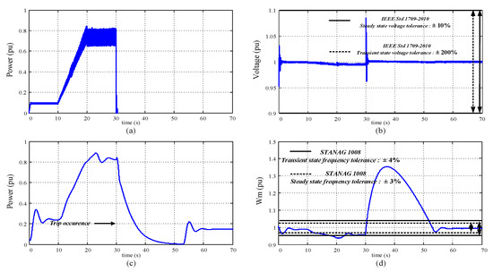
Figure 10.
Simulation results of the full propulsion load rejection (without the energy storage system): (a) Output power of the propulsion motor; (b) Main DC bus voltage; (c) Output power of the steam turbine; (d) Frequency of the generator.
As shown in Figure 8, Figure 9 and Figure 10, the transient and the steady state voltages satisfy the IEEE Std 1709–2010 limits. However, note that the energy storage system is required to reduce the fluctuation of the generator frequency and the transient times.
Figure 11 shows the simulation results that focused on the stability of the generator frequency after inserting the energy storage system to reduce the transient time. When the energy storage system is connected, the frequency excursion is reduced in all operating conditions. For two operating conditions (acceleration and deceleration, loss of prime mover trip), the transient of the frequency appears to be slightly higher than the limits of STANAG 1008. Despite the insertion of the energy storage system, the transient of the frequency excess and the transient time of full propulsion load rejection and does not satisfy the STANAG limits. In this case, from the operation of the power management system, the output power of the generator is reduced to maintain power for the ship service load. Table 2 shows the improved electrical characteristics of the transient and steady state voltages and the frequency by inserting the energy storage system into the main DC bus. The results (pass/fail) of transient and steady state were determined based on the STANAG 1008, even if energy storage system is connected, the full power load rejection case does not satisfy the frequency standard. In order to solve this problem an energy storage system with a sufficiently large capacity must be added.
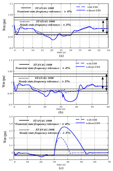
Figure 11.
Simulation results with the energy storage system: (a) Acceleration and deceleration; (b) Loss of prime mover; (c) Full propulsion load rejection.

Table 2.
Electrical characteristics according to the operation conditions.
5. Conclusions
Interest has been increasing in AES with a medium voltage DC power system. However, modeling and integration of the whole system is a complex and difficult task. To analyze the electrical characteristic of the medium voltage DC ship power system, this paper proposed the full simulation modeling of the AES with the mechanical and the electrical components by deriving the mathematical equations and using MATLAB/Simulink. The simulation was performed under three different ship operating conditions. The electrical characteristics of the AES that were related to DC bus voltage and generator frequency were analyzed according to the presence or absence of the energy storage system to meet IEEE Std 1709–2010 and STANAG 1008 standards. The effect of the energy storage system to improve the dynamic performance is shown at all operating conditions.
Author Contributions
Conceptualization, H.-K.K., C.-H.P. and J.-M.K.; validation, H.-K.K., C.-H.P. and J.-M.K.; formal analysis, H.-K.K. and C.-H.P.; investigation, H.-K.K.; writing—original draft preparation, H.-K.K.; writing—review and editing H.-K.K., C.-H.P. and J.-M.K. All authors have read and agreed to the published version of the manuscript.
Funding
This work was supported by a two-year research Grant of Pusan National University.
Institutional Review Board Statement
Not applicable.
Informed Consent Statement
Not applicable.
Data Availability Statement
Not applicable.
Conflicts of Interest
The authors declare no conflict of interest.
Appendix A
- (1)
- Steam turbine: Typical cylinder fractions (FVHP, FHP = 0.3, FIP = 0.4, FLP = 0.3), Typical Time constants (TCH = 0.1~0.4, TRH = 4~11, TRH2, TCO = 0.3~0.5), 3600 rpm [16,22,29].

Figure A1.
Configuration of the tandem compound steam turbine.
- (2)
- Governor & Excitation: Governor consists of gain setting, Speed relay, and servo motor (Droop 5%, IEEE standard DC1A excitation system model [17,18].
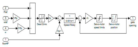
Figure A2.
Configuration of the governor system.
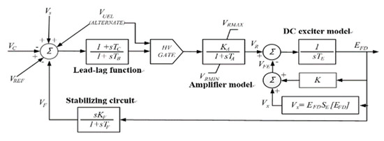
Figure A3.
Configuration of the IEEE type DC1A excitation model.
- (3)
- Synchronous generator: based on d-q equivalent circuit with 6.6 MW, 4160 V, 60 Hz, .
- (4)
- 3-phase permanent magnet motor: 12 MW, 150 rpm, .
- (5)
- 3-phase DC/AC PWM inverter: .
- (6)
- Ship model: to acquire thrust () and propeller torque () necessary to obtain propulsion motor speed (nm), ship parameter () and experimental data (). Ship speed is calculated by hull resistance [22,24].

Figure A4.
Configuration of the marine systems simulator (MSS).
- (7)
- DC/AC inverter, DC/DC converter: 3 phase DC/AC inverter for AC ship service load (300 kW/450 V/60 Hz), buck converter for DC ship service load (200 kW/200 V), bidirectional DC/DC converter between DC bus and Energy storage system.
- (8)
- Ship service load: 1 MW (capacitive, inductive, resistive) RLC load
- (9)
- Li-ion battery: 2 MW/500 kW, 4 C/rate, Li-ion battery charging/discharging comprehensive modeling

Table A1.
Specification of the Li-ion battery cell.
Table A1.
Specification of the Li-ion battery cell.
| Characteristics | Value |
|---|---|
| Nominal capacity | 31.5 Ah |
| Nominal voltage | 43.2 V |
| Charge limit | 49.2 V |
| Discharge limit | 30.0 V |
| Energy | 1.3 kWh |
| Maximum discharge current | 200 A |
Charging
Discharging
- , ,
- ,,
- , ,
- ,
- , .
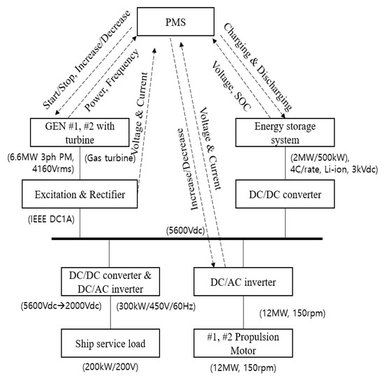
Figure A5.
Relationship with parameters for PMS.
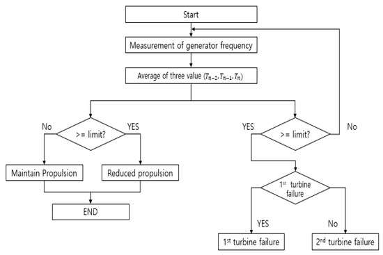
Figure A6.
Example of PMS operation in prime mover trip scenario.
References
- Kalsi, S.S.; Nayal, O. Ship electrical system simulation. In Proceedings of the IEEE Electric Ship Technologies Symposium, Philadelphia, PA, USA, 27 July 2005. [Google Scholar] [CrossRef]
- Hebner, R.E. Electric ship power system—Research at the University of Texas at Austin. In Proceedings of the IEEE Electric Ship Technologies Symposium, Philadelphia, PA, USA, 27 July 2005. [Google Scholar]
- Ku, H.K.; Seo, H.R.; Kim, J.M. Full simulation modeling for electrical analysis of all electric ships with medium voltage DC power system. In Proceedings of the 2015 9th International Conference on Power Electronics and ECCE Asia, Seoul, Korea, 1–5 June 2015; pp. 1955–1960. [Google Scholar]
- Norbert Doerry CAPT. Open Architecture Approach for the Next Generation Integrated Power System. In Proceedings of the ASNE Automation and Controls Symposium 2007, Biloxi, MS, USA, 10–11 December 2007. [Google Scholar]
- Zahedi, B.; Norum, L.E. Modeling and simulation of all-electric ships with low-voltage DC hybrid power systems. IEEE Trans. Power Electron. 2013, 28, 4525–4537. [Google Scholar] [CrossRef]
- Sulligoi, G.; Bosich, D.; Zhu, L.; Cupelli, M.; Monti, A. Linearizing Control of Shipboard Multi-Machine MVDC Power Systems feeding Constant Power Loads. In Proceedings of the 2012 IEEE Energy Conversion Congress and Exposition (ECCE), Raleigh, NC, USA, 15–20 September 2012. [Google Scholar]
- Arcidiacono, V.; Monti, A.; Sulligoi, G. Generation control system for improving design and stability of medium-voltage DC power systems on ships. Electr. Syst. Transp. IET 2012, 3, 158–167. [Google Scholar] [CrossRef]
- Wang, H.; Zhang, C.; Kong, X.; Zhang, H. Research on Transient Stability Simulation of Ship Power System. Adv. Mater. Res. 2012, 383–390, 2055–2059. [Google Scholar] [CrossRef]
- Jeon, W.; Wang, Y.P.; Jung, S.Y. Dynamic Characteristic Analysis at Each Operating Condition for Electric Ship Propulsion System. J. Korean Soc. Mar. Eng. 2008, 32, 1296–1302. [Google Scholar]
- Kulkarni, S.; Santoso, S. Estimating Transient Response of Simple AC and DC Shipboard Power Systems to Pulse Load Operations. In Proceedings of the IEEE Electric Ship Technologies Symposium, Baltimore, MD, USA, 20–22 April 2009. [Google Scholar]
- Sulligoi, G.; Bosich, D.; Arcidiacono, V.; Giadrossi, G. Considerations on the Design of Voltage Control for Multi-Machine MVDC Power Systems on Large Ships. In Proceedings of the 2013 IEEE Electric Ship Technologies Symposium (ESTS), Arlington, VA, USA, 22–24 April 2013. [Google Scholar]
- Sulligoi, G.; Vicenzutti, A.; Arcidiacono, V.; Khersonsky, Y. Voltage Stability in Large Marine-Integrated Electrical and Electronic Power Systems. IEEE Trans. Ind. Appl. 2016, 52, 3584–3594. [Google Scholar] [CrossRef]
- Sulligoi, G.; Vicenzutti, A.; Menis, R. All-Electric Ship Design: From Electrical Propulsion to Integrated Electrical and Electronic Power Systems. IEEE Trans. Trans. Elec. 2016, 2, 3584–3594. [Google Scholar] [CrossRef]
- Alafnan, H.; Zhang, M.; Yuan, W.; Zhu, J.; Li, J.; Elshiekh, M.; Li, X. Stability Improvement of DC Power Systems in an All-Electric Ship Using Hybrid SMES/Battery. IEEE Trans. Appl. Supercon. 2018, 28, 5700306. [Google Scholar] [CrossRef] [Green Version]
- Xu, Q.; Yang, B.; Han, Q.; Yuan, Y.; Chen, C.; Guan, X. Optimal Power Management for Failure Mode of MVDC Microgrids in All-Electric Ships. IEEE Trans. Pow. Sys. 2018, 34, 1054–1067. [Google Scholar] [CrossRef] [Green Version]
- IEEE Committee Report. Dynamic Models for Steam and Hydro Turbines in Power System Studies. IEEE Trans. Power Appar. Syst. 1973, 6, 1904–1915. [Google Scholar]
- Krause, P.C. Analysis of Electric Machinery, Section 12.5; McGraw-Hill: New York NY, USA, 1986. [Google Scholar]
- IEEE Std 421.5-2005; IEEE Recommended Practice for Excitation System Models for Power System Stability Studies, Energy Development and Power Generation Committee of the IEEE Power Engineering Society, 2005. IEEE: Piscataway, NJ, USA, 2016.
- Mohan, N.; Undeland, T.M.; Robbins, W.P. Power Electronics: Converters, applications and Design; John Wiley & Sons, Inc.: Hoboken, NJ, USA, 1995. [Google Scholar]
- Erickson, R.W. Fundamentals of Power Electronics; Springer: Berlin/Heidelberg, Germany, 2013. [Google Scholar]
- Sul, S.K. Control of Electric Machine Drive Systems; Wiley: New York, NY, USA, 2010. [Google Scholar]
- Fossen, T.I. Handbook of Marine Craft Hydrodynamics and Motion Control; Wiley: New York, NY, USA, 2011. [Google Scholar]
- Zahedi, B.; Norum, L.E. Modelling and Simulation of Hybrid Electric Ships with DC Distribution Systems, Norwegian University of Science and Technology (NTNU). In Proceedings of the 2013 15th European Conference on Power Electronics and Applications (EPE), Lille, France, 2–6 September2013. [Google Scholar]
- Perez, T.; Smogeli, O.; Fossen, T.; Sorensen, A.J. An Overview of the Marine Systems Simulator (MSS): A Simulink Toolbox for Marine Control Systems. Modeling Identif. Control 2006, 27, 259–275. [Google Scholar] [CrossRef] [Green Version]
- Monti, A.; Darco, S.; Gao, L.; Dougal, R.A. Energy storage management as key issue in control of power systems in future all electric ships. In Proceedings of the 2008 International Symposium on Power Electronics, Electrical Drives, Automation and Motion, Ischia, Italy, 11–13 June 2008; pp. 580–585. [Google Scholar]
- Hebner, R.E.; Herbst, J.; Gattozzi, A. Large scale simulations of a ship power system with energy storage and multiple directed energy loads. In Proceedings of the 2010 Grand Challenges in Modeling & Simulation (GCMS 2010), Ottawa, ON, Canada, 11–14 July 2010; pp. 430–435. [Google Scholar]
- Pascal, M.; Rachid, C.; Alexandre, O. Optimizing a battery energy storage system for frequency control application in an isolated power system. IEEE Trans. Power Syst. 2009, 24, 1469–1477. [Google Scholar]
- Hebner, R.E.; Davey, K.; Herbst, J.; Hall, D.; Hahne, J.; Surls, D.D.; Ouroua, A. Dynamic Load and Storage Integration. Proc. IEEE 2015, 103, 2344–2354. [Google Scholar] [CrossRef] [Green Version]
- Jadric, I.; Borojevic, D.; Jadric, M. Modeling and control of a synchronous generator with an active DC load. IEEE Trans. Power Elec. 2000, 15, 303–311. [Google Scholar] [CrossRef]
- Khan, M.M.S.; Faruque, M.O.; Newaz, A. Fuzzy Logic Based Energy Storage Management System for MVDC Power System of All Electric Ship. IEEE Trans. Energy Conv. 2017, 32, 798–809. [Google Scholar] [CrossRef] [Green Version]
- Seenumani, G.; Sun, J.; Peng, H. A hierarchical optimal control strategy for power management of hybrid power systems in all electric ships applications. In Proceedings of the 2010 49th IEEE Conference on Decision and Control (CDC), Atlanta, GA, USA, 15–17 December 2010; pp. 3972–3977. [Google Scholar]
- Qunying, S.; Ramachandran, B.; Srivastava, S.K.; Andrus, M.; Cartes, D.A. Power and Energy Management in Integrated Power System. In Proceedings of the 2011 IEEE Electric Ship Technologies Symposium (ESTS), Alexandria, VA, USA, 10–13 April 2011; pp. 414–419. [Google Scholar]
- Damir, R. Integrated Control of Marine Electrical Power Systems. Fakultet for Ingeniørvitenskap Og Teknologi: Trondheim, Norway; ISBN 978-82-471-6647-5.
- IEEE Standard 1662-2008; Guide for the Design and Application of Power Electronics in Electrical Power Systems on Ships. IEEE: Piscataway, NJ, USA, 2009.
- Chua, L.W.Y.; Tjahjowidodo, T.; Seet, G.G.L.; Chan, R. Implementation of Optimization-Based Power Management for All-Electric Hybrid Vessels. IEEE Access 2018, 6, 74339–74354. [Google Scholar] [CrossRef]
- Satpathi, K.; Ukil, A.; Nag, S.S.; Pou, J.; Zagrodnik, M.A. DC Marine Power System: Transient Behavior and Fault Management Aspects. IEEE Trans. Indus. Inform. 2019, 15, 1911–1925. [Google Scholar] [CrossRef]
- IEEE Std 45-1998; IEEE Recommended Practice for Electrical Installation on Shipboard. IEEE: Piscataway, NJ, USA, 1998.
- IEEE Std 1709-2010; IEEE Recommended Practice for 1kV to 35kV Medium-Voltage DC Power Systems on Ships, DC Power Systems on Ships Working Group of the IEEE Industry Applications Society Petroleum & Chemical Industry (IAS/PCI) Committee. IEEE: Piscataway, NJ, USA, 2010.
- STANAG 1008 Characteristics of Shipboard Electrical Power Systems in Warships of the North Atlantic Treaty Navies, 9th ed.; NATO: Brussels, Belgium, 2004.
- MIL-STD-1399, Section 680; Navy High Voltage Power, Alternating Current. Department of Defense: Arlington, VA, USA, 24 April 2008.
Publisher’s Note: MDPI stays neutral with regard to jurisdictional claims in published maps and institutional affiliations. |
© 2022 by the authors. Licensee MDPI, Basel, Switzerland. This article is an open access article distributed under the terms and conditions of the Creative Commons Attribution (CC BY) license (https://creativecommons.org/licenses/by/4.0/).