
Predictive Control of PV/Battery System under Load and Environmental Uncertainty

 ,
,  ,
,  ,
,
Abstract
:1. Introduction
- A detailed mathematical model for the study system is developed. The model includes the complete mathematical model of the PV panels, battery system, converter dynamics and the dc bus.
- A nonlinear MPC based on the ARIMA algorithm has been proposed to effectively manage the power flow in a standalone dc microgrid with a PV-BESS-load system that has fast variations in the load and environmental conditions.
- The paper considers the various operational modes in the power management strategy such as power curtailment of the PV and proper charging/discharging of the battery. The maximum and minimum state of charge of the battery is considered to prevent it from over/under charge conditions.
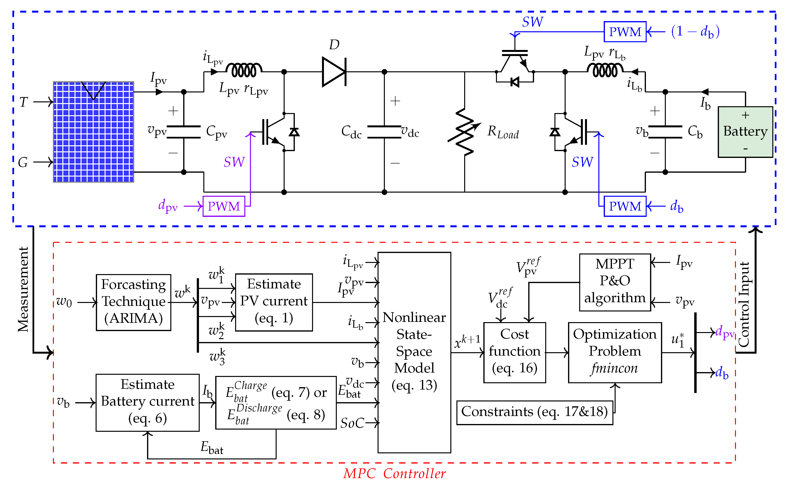
2. Study System
2.1. Mathematical Modeling
2.1.1. Model of PV Subsystem
2.1.2. Model of Battery Energy Storage Subsystem
2.1.3. Model of the DC Bus
2.2. State Space Model of the Considered System
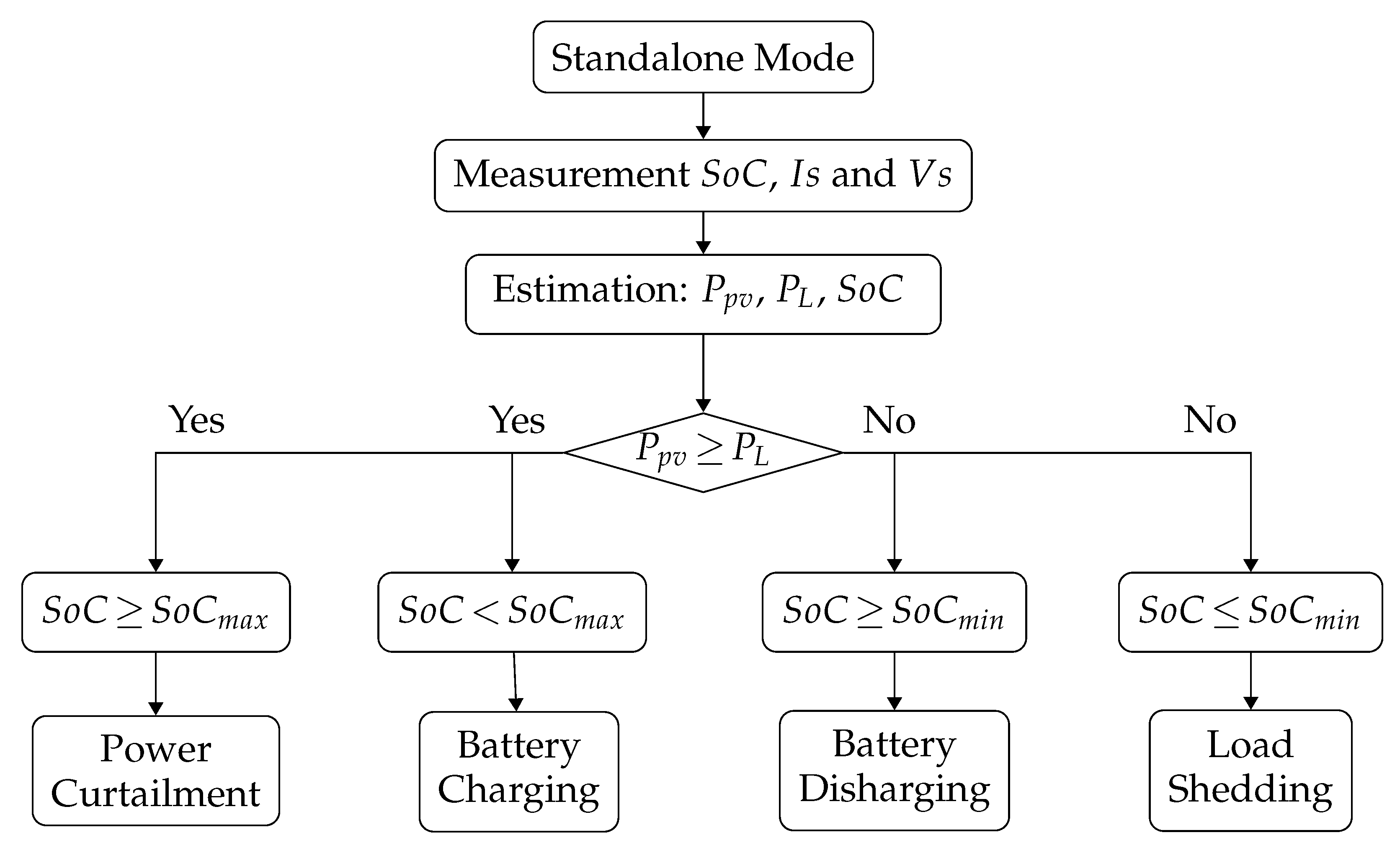
3. Power Management Strategy
Operational Modes
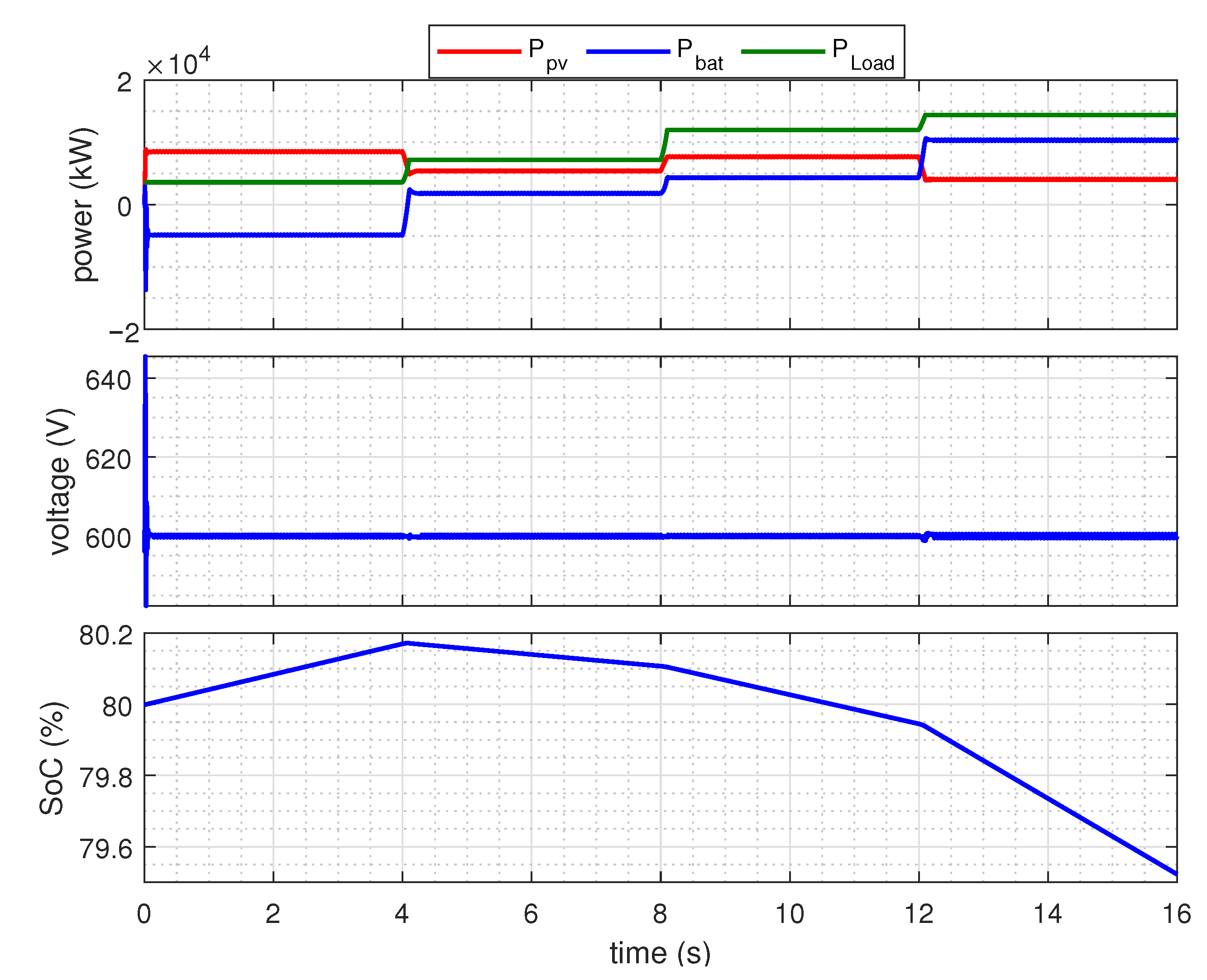
- Mode I ( and ): In this mode, the available power from the PV is greater than the load demand, and the battery can absorb extra power. The PV operates at MPP while the battery regulates the common DC bus voltage at its nominal value.
- Mode II ( and ): In this mode, the power from the PV is not enough to meet the load demand. Therefore, the battery discharges to meet the extra load. Similar to Mode I, the PV operates at MPP and the battery regulates the voltage of the DC bus.
- Mode III ( and ): If the battery is fully charged and the available PV power exceeds the load demand, the battery current is set at zero to prevent it from overcharging, and the PV power is curtailed. The power curtailment is achieved by operating the PV to regulate the DC bus voltage at its nominal value.
- Mode IV ( and ): During cloudy days and at night, the PV power is not available. The PV, in this mode, is disconnected, and the battery regulates DC bus voltage to meet the load demand.
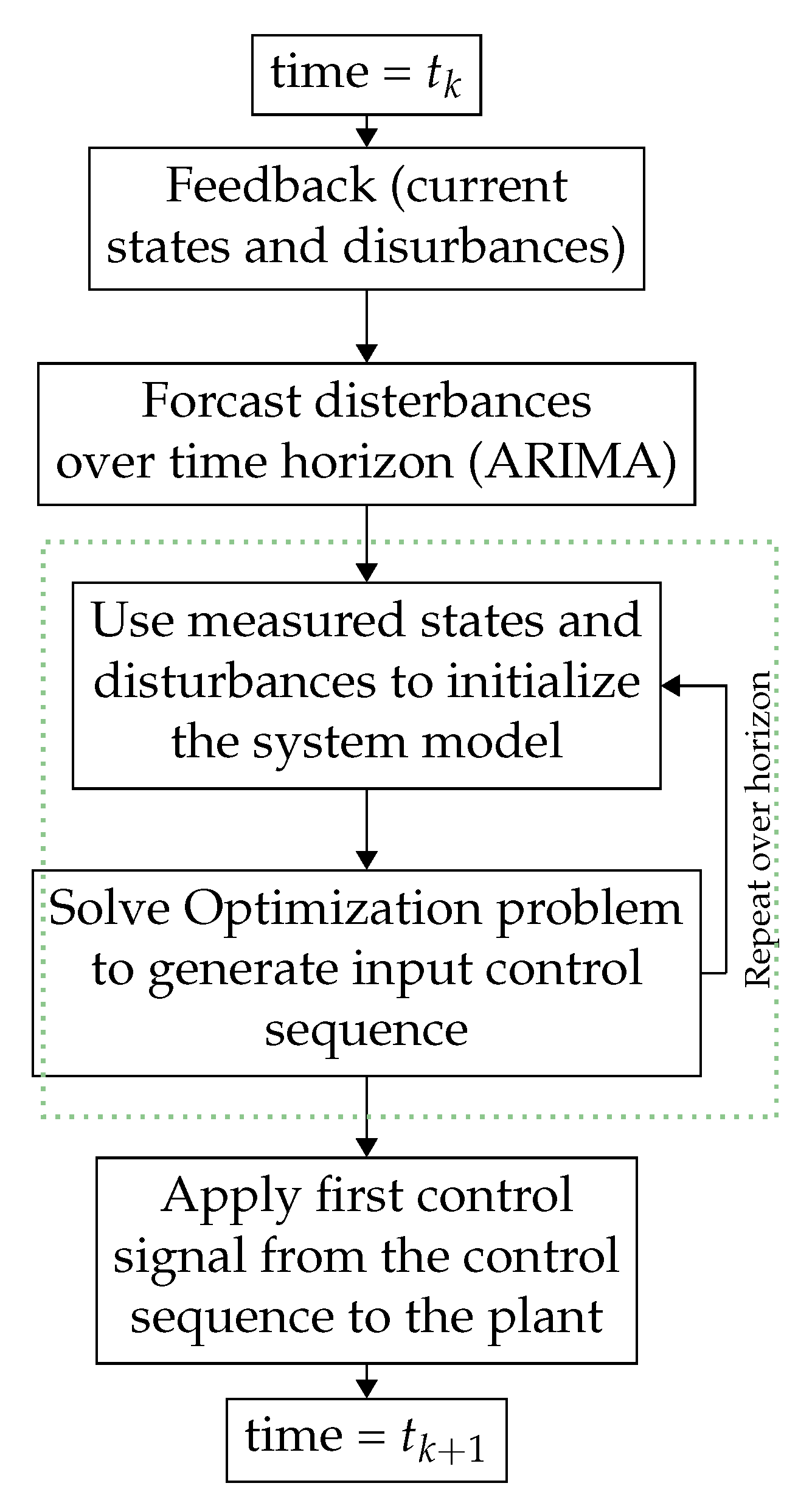
4. The Proposed MPC-Based Control Method
4.1. Model Predictive Control Approach
4.2. Control Problem Formulation
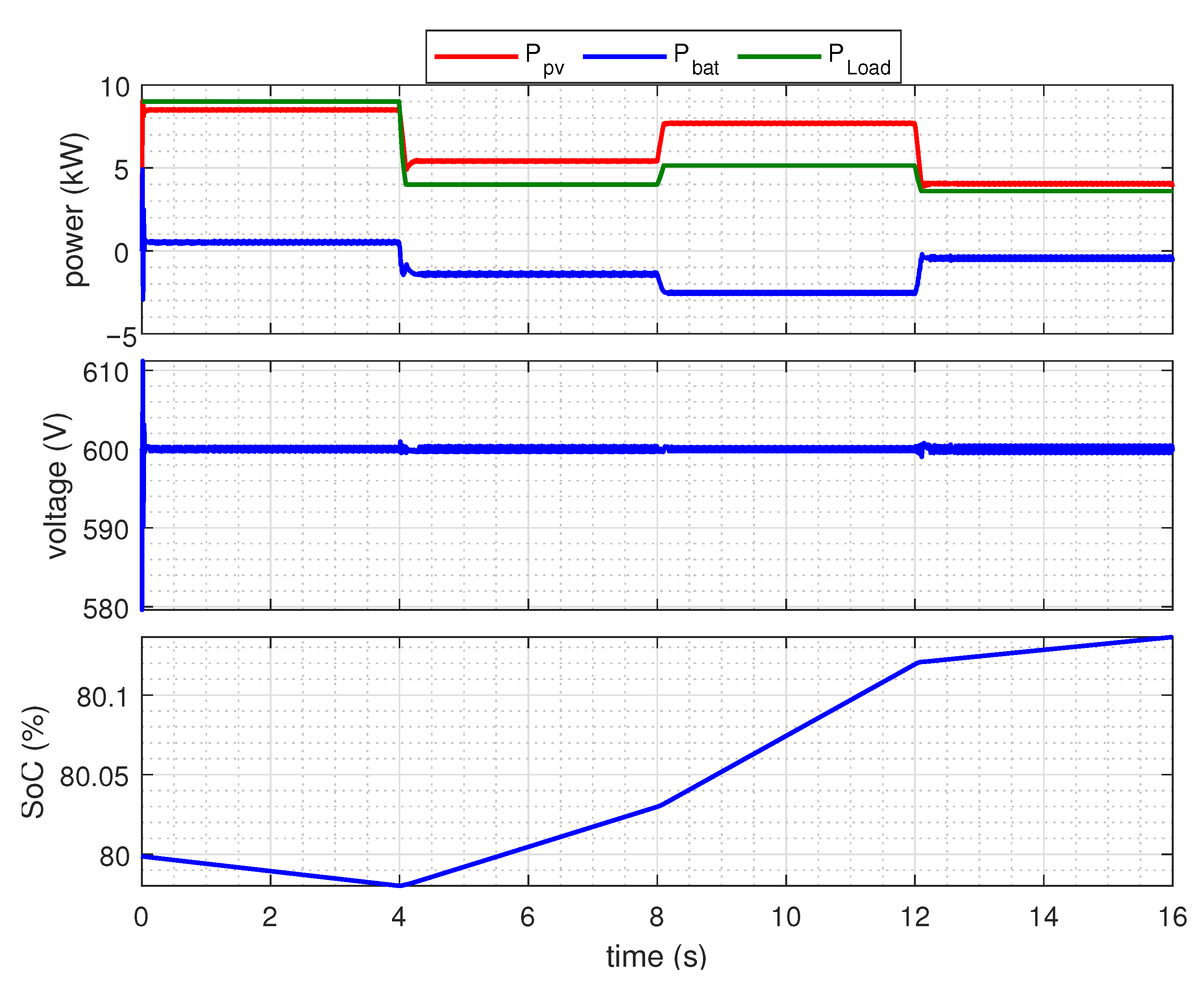
5. Simulation Results
5.1. Mode I Operation
5.2. Mode II Operation
5.3. Mode III Operation
5.4. Mode IV Operation
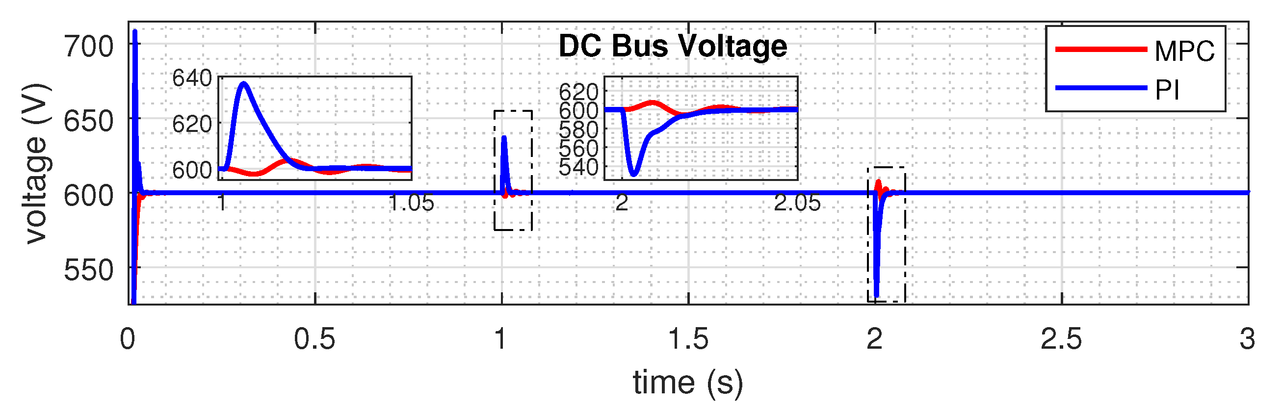
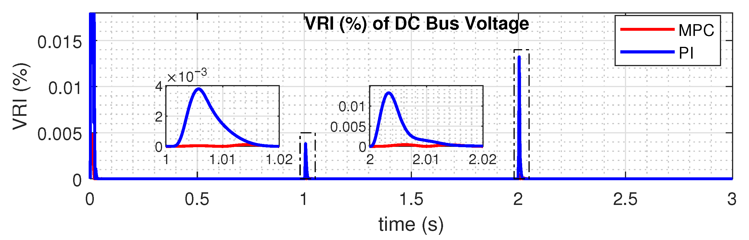
5.5. Comparison of the Proposed Controller with PI Controller
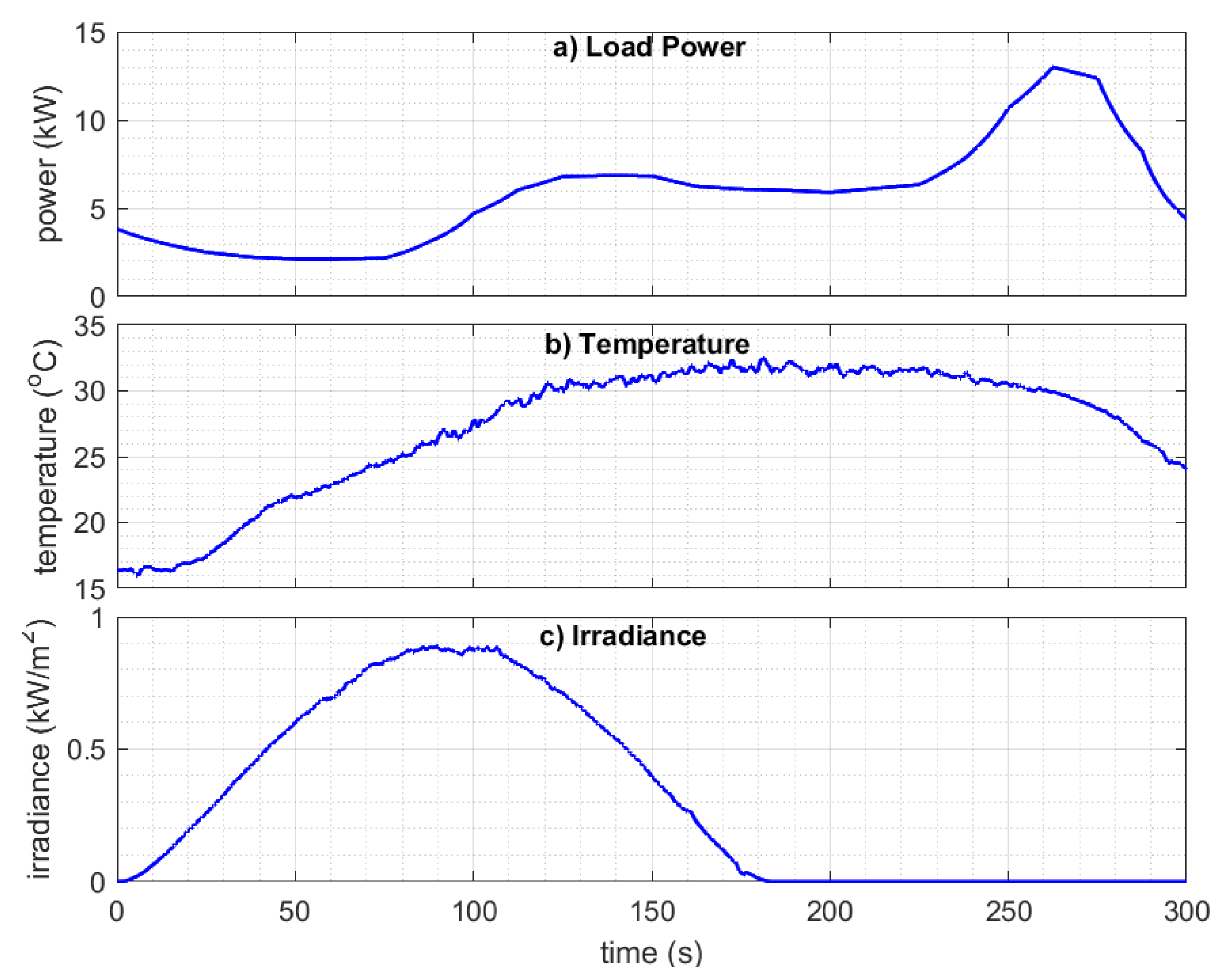
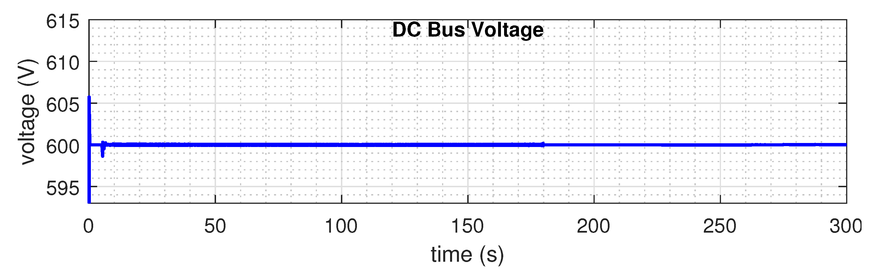
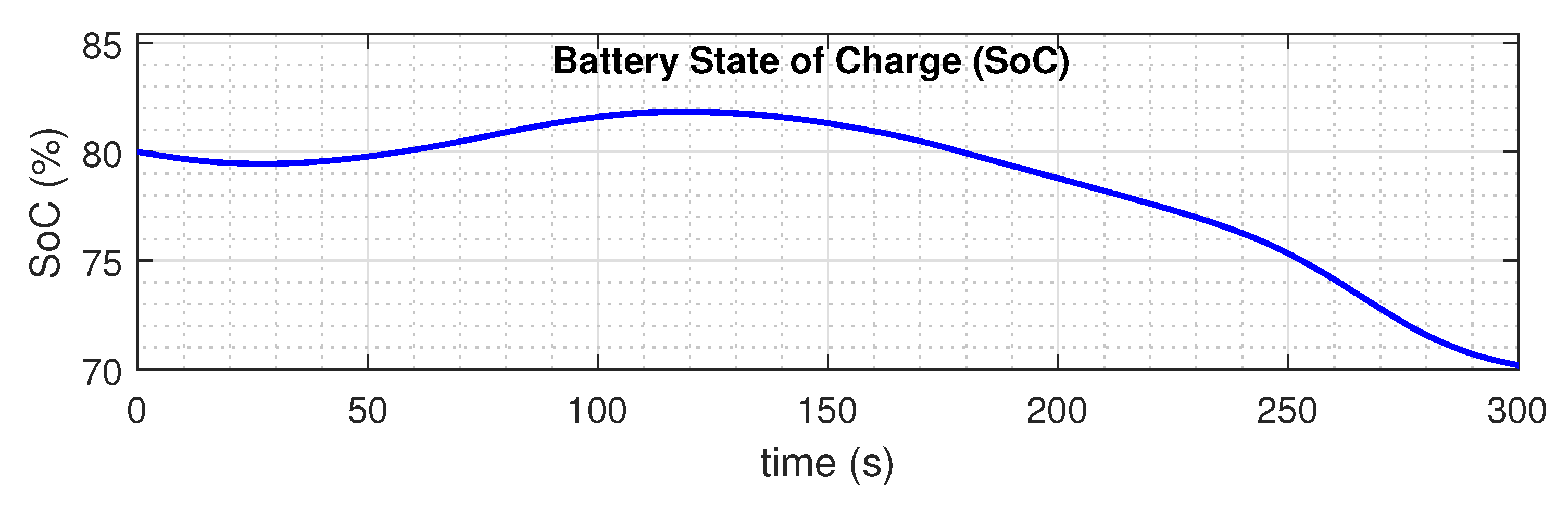
5.6. Response of the Proposed Control to the Real-World Environmental and Load Profile
6. Conclusions
Author Contributions
Funding
Institutional Review Board Statement
Informed Consent Statement
Data Availability Statement
Conflicts of Interest
References
- Zia, M.F.; Benbouzid, M.; Elbouchikhi, E.; Muyeen, S.M.; Techato, K.; Guerrero, J.M. Microgrid Transactive Energy: Review, Architectures, Distributed Ledger Technologies, and Market Analysis. IEEE Access 2020, 8, 19410–19432. [Google Scholar] [CrossRef]
- Annual Energy Outlook 2020 with Projections to 2050. 2020. Available online: https://www.eia.gov/outlooks/aeo/pdf/aeo2020.pdf (accessed on 19 April 2022).
- Qunais, T.; Sharma, R.; Karimi-Ghartemani, M.; Silwal, S.; Khajehoddin, S.A. Application of Battery Storage System to Improve Transient Responses in a Distribution Grid. In Proceedings of the 2019 IEEE 28th International Symposium on Industrial Electronics (ISIE), Vancouver, BC, Canada, 12–14 June 2019; pp. 52–57. [Google Scholar] [CrossRef]
- Sharma, R.; Karimi-Ghartemani, M. Addressing Abrupt PV Disturbances, and Mitigating Net Load Profile’s Ramp and Peak Demands, Using Distributed Storage Devices. Energies 2020, 13, 1024. [Google Scholar] [CrossRef] [Green Version]
- Sharma, R.; Zakerian, A.; Karimi-Ghartemani, M. Local Controller for an Autonomous Grid-Supportive Battery Energy Storage System. IEEE Trans. Power Electron. 2021, 37, 2191–2202. [Google Scholar] [CrossRef]
- Nejabatkhah, F.; Li, Y.W. Overview of Power Management Strategies of Hybrid AC/DC Microgrid. IEEE Trans. Power Electron. 2015, 30, 7072–7089. [Google Scholar] [CrossRef]
- Merabet, A.; Ahmed, K.T.; Ibrahim, H.; Beguenane, R.; Ghias, A.M. Energy management and control system for laboratory scale microgrid based wind-PV-battery. IEEE Trans. Sustain. Energy 2017, 8, 145–154. [Google Scholar] [CrossRef]
- Cai, H.; Xiang, J.; Wei, W. Decentralized Coordination Control of Multiple Photovoltaic Sources for DC Bus Voltage Regulating and Power Sharing. IEEE Trans. Ind. Electron. 2018, 65, 5601–5610. [Google Scholar] [CrossRef]
- Mahmood, H.; Jiang, J. Decentralized Power Management of Multiple PV, Battery, and Droop Units in an Islanded Microgrid. IEEE Trans. Smart Grid 2019, 10, 1898–1906. [Google Scholar] [CrossRef]
- Karimi, Y.; Guerrero, J.M.; Oraee, H. Decentralized method for load sharing and power management in a hybrid single/three-phase islanded microgrid consisting of hybrid source PV/battery units. In Proceedings of the 2016 IEEE Energy Conversion Congress and Exposition (ECCE), Milwaukee, WI, USA, 18–22 September 2016; pp. 1–8. [Google Scholar] [CrossRef] [Green Version]
- Yi, Z.; Dong, W.; Etemadi, A.H. A Unified Control and Power Management Scheme for PV-Battery-Based Hybrid Microgrids for Both Grid-Connected and Islanded Modes. IEEE Trans. Smart Grid 2018, 9, 5975–5985. [Google Scholar] [CrossRef]
- Bayat, F. Model Predictive Sliding Control for Finite-Time Three-Axis Spacecraft Attitude Tracking. IEEE Trans. Ind. Electron. 2019, 66, 7986–7996. [Google Scholar] [CrossRef]
- He, H.; Jia, H.; Sun, C.; Sun, F. Stochastic Model Predictive Control of Air Conditioning System for Electric Vehicles: Sensitivity Study, Comparison, and Improvement. IEEE Trans. Ind. Inform. 2018, 14, 4179–4189. [Google Scholar] [CrossRef]
- Wang, D.; Xiang, H. Composite Control of Post-Chlorine Dosage During Drinking Water Treatment. IEEE Access 2019, 7, 27893–27898. [Google Scholar] [CrossRef]
- Parisio, A.; Rikos, E.; Glielmo, L. A Model Predictive Control Approach to Microgrid Operation Optimization. IEEE Trans. Control. Syst. Technol. 2014, 22, 1813–1827. [Google Scholar] [CrossRef]
- Ouammi, A.; Dagdougui, H.; Dessaint, L.; Sacile, R. Coordinated Model Predictive-Based Power Flows Control in a Cooperative Network of Smart Microgrids. IEEE Trans. Smart Grid 2015, 6, 2233–2244. [Google Scholar] [CrossRef]
- Abdeltawab, H.H.; Mohamed, Y.A.I. Market-Oriented Energy Management of a Hybrid Wind-Battery Energy Storage System Via Model Predictive Control With Constraint Optimizer. IEEE Trans. Ind. Electron. 2015, 62, 6658–6670. [Google Scholar] [CrossRef]
- Minchala-Avila, L.I.; Garza-Castañon, L.; Zhang, Y.; Ferrer, H.J.A. Optimal Energy Management for Stable Operation of an Islanded Microgrid. IEEE Trans. Ind. Inform. 2016, 12, 1361–1370. [Google Scholar] [CrossRef] [Green Version]
- Hooshmand, A.; Malki, H.A.; Mohammadpour, J. Power flow management of microgrid networks using model predictive control. Comput. Math. Appl. 2012, 64, 869–876. [Google Scholar] [CrossRef] [Green Version]
- Lee, J.; Kim, Y.; Moon, S. Novel Supervisory Control Method for Islanded Droop-Based AC/DC Microgrids. IEEE Trans. Power Syst. 2019, 34, 2140–2151. [Google Scholar] [CrossRef]
- Lei, M.; Yang, Z.; Wang, Y.; Xu, H.; Meng, L.; Vasquez, J.C.; Guerrero, J.M. An MPC-Based ESS Control Method for PV Power Smoothing Applications. IEEE Trans. Power Electron. 2018, 33, 2136–2144. [Google Scholar] [CrossRef] [Green Version]
- Hredzak, B.; Agelidis, V.G.; Jang, M. A model predictive control system for a hybrid battery-ultracapacitor power source. IEEE Trans. Power Electron. 2014, 29, 1469–1479. [Google Scholar] [CrossRef]
- Dragičević, T. Model Predictive Control of Power Converters for Robust and Fast Operation of AC Microgrids. IEEE Trans. Power Electron. 2018, 33, 6304–6317. [Google Scholar] [CrossRef]
- Tan, K.; So, P.; Chu, Y.; Chen, M. Coordinated control and energy management of distributed generation inverters in a microgrid. IEEE Trans. Power Deliv. 2013, 28, 704–713. [Google Scholar] [CrossRef] [Green Version]
- Yi, Z.; Zhao, X.; Shi, D.; Duan, J.; Xiang, Y.; Wang, Z. Accurate Power Sharing and Synthetic Inertia Control for DC Building Microgrids With Guaranteed Performance. IEEE Access 2019, 7, 63698–63708. [Google Scholar] [CrossRef]
- Tavakoli, A.; Negnevitsky, M.; Muttaqi, K.M. A decentralized model predictive control for operation of multiple distributed generators in an islanded mode. IEEE Trans. Ind. Appl. 2017, 53, 1466–1475. [Google Scholar] [CrossRef]
- Tan, K.; Peng, X.; So, P.L.; Chu, Y.C.; Chen, M. Centralized control for parallel operation of distributed generation inverters in microgrids. IEEE Trans. Smart Grid 2012, 3, 1977–1987. [Google Scholar] [CrossRef] [Green Version]
- Shan, Y.; Hu, J.; Chan, K.W.; Fu, Q.; Guerrero, J.M. Model Predictive Control of Bidirectional DC-DC Converters and AC/DC Interlinking Converters-A New Control Method for PV-Wind-Battery Microgrids. IEEE Trans. Sustain. Energy 2018, 10, 1823–1833. [Google Scholar] [CrossRef]
- Kou, P.; Liang, D.; Wang, J.; Gao, L. Stable and Optimal Load Sharing of Multiple PMSGs in an Islanded DC Microgrid. IEEE Trans. Energy Convers. 2018, 33, 260–271. [Google Scholar] [CrossRef]
- Mardani, M.M.; Khooban, M.H.; Masoudian, A.; Dragičević, T. Model Predictive Control of DC–DC Converters to Mitigate the Effects of Pulsed Power Loads in Naval DC Microgrids. IEEE Trans. Ind. Electron. 2019, 66, 5676–5685. [Google Scholar] [CrossRef] [Green Version]
- Batiyah, S.; Zohrabi, N.; Abdelwahed, S.; Sharma, R. An MPC-Based Power Management of a PV/Battery System in an Islanded DC Microgrid. In Proceedings of the 2018 IEEE Transportation Electrification Conference and Expo (ITEC), Long Beach, CA, USA, 13–15 June 2018; pp. 231–236. [Google Scholar]
- Batiyah, S.; Sharma, R.; Abdelwahed, S.; Zohrabi, N. An MPC-based power management of standalone DC microgrid with energy storage. Int. J. Electr. Power Energy Syst. 2020, 120, 105949. [Google Scholar] [CrossRef]
- Motapon, S.N.; Lupien-Bedard, A.; Dessaint, L.; Fortin-Blanchette, H.; Al-Haddad, K. A Generic Electrothermal Li-ion Battery Model for Rapid Evaluation of Cell Temperature Temporal Evolution. IEEE Trans. Ind. Electron. 2017, 64, 998–1008. [Google Scholar] [CrossRef]
- Tremblay, O.; Dessaint, L.A. Experimental validation of a battery dynamic model for EV applications. World Electr. Veh. J. 2009, 3, 289–298. [Google Scholar] [CrossRef] [Green Version]
- Li, X.; Wang, Q.; Wen, H.; Xiao, W. Comprehensive Studies on Operational Principles for Maximum Power Point Tracking in Photovoltaic Systems. IEEE Access 2019, 7, 121407–121420. [Google Scholar] [CrossRef]
- Yunus, K.; Thiringer, T.; Chen, P. ARIMA-Based Frequency-Decomposed Modeling of Wind Speed Time Series. IEEE Trans. Power Syst. 2016, 31, 2546–2556. [Google Scholar] [CrossRef]
- Karimi-Ghartemani, M.; Khajehoddin, S.A.; Jain, P.; Bakhshai, A. Linear quadratic output tracking and disturbance rejection. Int. J. Control 2011, 84, 1442–1449. [Google Scholar] [CrossRef]
- Yoder, M.; Andreas, A. Lowry Range Solar Station: Arapahoe County, Colorado (Data); National Renewable Energy Laboratory: Golden, CO, USA, 2014. [Google Scholar]
- Li, X. Microgrid Load and LCOE Modelling Results; National Renewable Energy Laboratory: Golden, CO, USA, 2018. [Google Scholar]


| Parameter | Symbol | Value |
|---|---|---|
| PV Capacitor | 300 F | |
| PV Inductor | 10 mH | |
| Resistance of Inductance | 10 m | |
| Battery Capacitor | 300 F | |
| Battery Inductor | 10 mH | |
| Resistance of Inductance | 10 m | |
| DC bus Capacitor | 1500 F | |
| Switch Frequency | 10 kHz | |
| PV Parameters | ||
| Maximum Power | 213.15 W | |
| MP, OC Voltage | , | 29 V, 36.3 V |
| SC, MP Current | 7.84 A, 7.35 A | |
| battery parameters | ||
| Battery Voltage | 300 V | |
| Battery Capacity | Q | 20 Ah |
Publisher’s Note: MDPI stays neutral with regard to jurisdictional claims in published maps and institutional affiliations. |
© 2022 by the authors. Licensee MDPI, Basel, Switzerland. This article is an open access article distributed under the terms and conditions of the Creative Commons Attribution (CC BY) license (https://creativecommons.org/licenses/by/4.0/).
Share and Cite
Batiyah, S.; Sharma, R.; Abdelwahed, S.; Alhosaini, W.; Aldosari, O. Predictive Control of PV/Battery System under Load and Environmental Uncertainty. Energies 2022, 15, 4100. https://doi.org/10.3390/en15114100
Batiyah S, Sharma R, Abdelwahed S, Alhosaini W, Aldosari O. Predictive Control of PV/Battery System under Load and Environmental Uncertainty. Energies. 2022; 15(11):4100. https://doi.org/10.3390/en15114100
Chicago/Turabian StyleBatiyah, Salem, Roshan Sharma, Sherif Abdelwahed, Waleed Alhosaini, and Obaid Aldosari. 2022. "Predictive Control of PV/Battery System under Load and Environmental Uncertainty" Energies 15, no. 11: 4100. https://doi.org/10.3390/en15114100
APA StyleBatiyah, S., Sharma, R., Abdelwahed, S., Alhosaini, W., & Aldosari, O. (2022). Predictive Control of PV/Battery System under Load and Environmental Uncertainty. Energies, 15(11), 4100. https://doi.org/10.3390/en15114100