
Grid-Forming Operation of Energy-Router Based on Model Predictive Control with Improved Dynamic Performance

 ,
, 
 and
and 
Abstract
:1. Introduction
2. Conventional Grid-Forming Control Systems and Problem Definition
3. Grid-Forming Operations Based on Indirect Model Predictive Control
4. Optimal Parameters Selection
5. Conclusions
Author Contributions
Funding
Institutional Review Board Statement
Informed Consent Statement
Data Availability Statement
Conflicts of Interest
References
- Liu, Y.; Fang, Y.; Li, J. Interconnecting microgrids via the energy router with smart energy management. Energies 2017, 10, 1297. [Google Scholar] [CrossRef] [Green Version]
- Huang, A.Q.; Crow, M.L.; Heydt, G.T.; Zheng, J.P.; Dale, S.J. The future renewable electric energy delivery and management (FREEDM) system: The energy internet. Proc. IEEE 2011, 99, 133–148. [Google Scholar] [CrossRef]
- Roncero-Clemente, C.; Vilhena, N.; Delgado-Gomes, V.; Romero-Cadaval, E.; Martins, J.F. Control and operation of a three-phase local energy router for prosumers in a smart community. IET Renew. Power Gener. 2020, 14, 560–570. [Google Scholar] [CrossRef] [Green Version]
- Martins, J.F.; Romero-Cadaval, E.; Vinnikov, D.; Malinowski, M. Transactive Electronics Power Energy: Challenges. IEEE Power Electron. Mag. 2022, 9, 20–32. [Google Scholar] [CrossRef]
- Liu, Y.; Li, J.; Wu, Y.; Zhou, F. Coordinated Control of the Energy Router-Based Smart Home Energy Management System. Appl. Sci. 2017, 7, 943. [Google Scholar] [CrossRef] [Green Version]
- Fu, R.; Remo, T.; Margolis, R.; Fu, R.; Remo, T.; Margolis, R. 2018 U.S. Utility-Scale Photovoltaics-Plus-Energy Storage System Costs Benchmark. 2018. Available online: https://www.nrel.gov/docs/fy19osti/71714.pdf.%0Ahttps://www.nrel.gov/docs/fy19osti/71714.pdf (accessed on 21 November 2018).
- Liu, Y.; Chen, X.; Wu, Y.; Yang, K.; Zhu, J.; Li, B. Enabling the Smart and Flexible Management of Energy Prosumers via the Energy Router with Parallel Operation Mode. IEEE Access 2020, 8, 35038–35047. [Google Scholar] [CrossRef]
- Liu, Y.; Li, Y.; Liang, H.; He, J.; Cui, H. Energy Routing Control Strategy for Integrated Microgrids Including Photovoltaic, Battery-Energy Storage and Electric Vehicles. Energies 2019, 12, 302. [Google Scholar] [CrossRef] [Green Version]
- Ray, O.; Mishra, S. Integrated Hybrid Output Converter as Power Router for Renewable-based Nanogrids. In Proceedings of the ECON 2015—41st Annual Conference of the IEEE Industrial Electronics Society, Yokohama, Japan, 9–12 November 2015; pp. 1645–1650. [Google Scholar]
- Zhen, L.; Penghua, L.; Wanxing, S.; Songhuai, D.; Qing, D.; Zhipeng, L. Research on a household energy router for energy internet. In Proceedings of the 2018 13th IEEE Conference on Industrial Electronics and Applications (ICIEA), Wuhan, China, 31 May–2 June 2018; pp. 952–957. [Google Scholar] [CrossRef]
- Tarafdar, M.H.; Hamzeh, F. Aghdam Smart Hybrid Nanogrids Using Modular Multiport Power Electronic Interface. In Proceedings of the 2016 IEEE Innovative Smart Grid Technologies—Asia (ISGT-Asia), Melbourne, VIC, Australia, 28 November–1 December 2016; pp. 11–16. [Google Scholar]
- Mishra, S.; Ray, O. Advances in nanogrid technology and its integration into rural electrification in India. In Proceedings of the 2014 International Power Electronics Conference (IPEC-Hiroshima 2014—ECCE ASIA), Hiroshima, Japan, 18–21 May 2014; pp. 2707–2713. [Google Scholar] [CrossRef]
- Majumder, R. A hybrid microgrid with dc connection at back to back converters. IEEE Trans. Smart Grid 2014, 5, 251–259. [Google Scholar] [CrossRef]
- Najafzadeh, M.; Husev, O.; Roasto, I.; Jalakas, T. Improved DC-Link Voltage Transient Response and Stability Issues in Energy Router with Fuzzy Logic Control Method. In Proceedings of the 2020 IEEE 61th International Scientific Conference on Power and Electrical Engineering of Riga Technical University (RTUCON), Riga, Latvia, 5–7 November 2020. [Google Scholar]
- Roasto, I.; Rosin, A.; Jalakas, T. Multiport Interface Converter with an Energy Storage for Nanogrids. In Proceedings of the IECON 2018—44th Annual Conference of the IEEE Industrial Electronics Society, Washington, DC, USA, 21–23 October 2018; Volume 1, pp. 6088–6093. [Google Scholar]
- Najafzadeh, M.; Roasto, I.; Jalakas, T. Energy Router Based Energy Management System for Nearly Zero Energy Buildings. In Proceedings of the 2019 IEEE 60th International Scientific Conference on Power and Electrical Engineering of Riga Technical University (RTUCON), Riga, Latvia, 7–9 October 2019. [Google Scholar]
- Yang, Y.; Hadjidemetriou, L.; Blaabjerg, F.; Kyriakides, E. Benchmarking of Phase Locked Loop based Synchronization Techniques for Grid-Connected Inverter Systems. In Proceedings of the 9th International Conference on Power Electronics—ECCE Asia, Seoul, Korea, 1–5 June 2015; pp. 2167–2174. [Google Scholar]
- Husev, O.; Roncero-Clemente, C.; Makovenko, E.; Pimentel, S.P.; Vinnikov, D.; Martins, J. Optimization and Implementation of the Proportional-Resonant Controller for Grid-Connected Inverter with Significant Computation Delay. IEEE Trans. Ind. Electron. 2020, 67, 1201–1211. [Google Scholar] [CrossRef]
- Rocabert, J.; Luna, A.; Blaabjerg, F.; Rodriguez, P. Control of Power Converters in AC Microgrids. IEEE Trans. Power Electron. 2012, 27, 4734–4749. [Google Scholar] [CrossRef]
- Hossain, M.J.A.J.; Pota, H.R.; Issa, W.; Hossain, M.J.A.J. Overview of AC microgrid controls with inverter-interfaced generations. Energies 2017, 10, 1300. [Google Scholar] [CrossRef]
- Unamuno, E.; Barrena, J.A. Hybrid ac/dc microgrids—Part II: Review and classification of control strategies. Renew. Sustain. Energy Rev. 2015, 52, 1123–1134. [Google Scholar] [CrossRef]
- Malik, S.M.; Ai, X.; Sun, Y.; Zhengqi, C.; Shupeng, Z. Voltage and frequency control strategies of hybrid AC/DC microgrid: A review. IET Gener. Transm. Distrib. 2017, 11, 303–313. [Google Scholar] [CrossRef]
- Loh, P.C.; Li, D.; Chai, Y.K.; Blaabjerg, F. Autonomous control of interlinking converter with energy storage in hybrid AC-DC microgrid. IEEE Trans. Ind. Appl. 2013, 49, 1374–1382. [Google Scholar] [CrossRef]
- Tayab, U.B.; Roslan, M.A.B.; Hwai, L.J.; Kashif, M. A review of droop control techniques for microgrid. Renew. Sustain. Energy Rev. 2017, 76, 717–727. [Google Scholar] [CrossRef]
- Guerrero, J.M.; de Vicuña, L.G.; Matas, J.; Castilla, M. Output Impedance Design of Parallel-Connected UPS Inverters with Wireless Load-Sharing Control. IEEE Trans. Ind. Electron. 2005, 52, 1126–1135. [Google Scholar] [CrossRef]
- Zhang, H.; Zhou, J.; Sun, Q.; Guerrero, J.M.; Ma, D. Data-Driven Control for Interlinked AC/DC Microgrids Via Model-Free Adaptive Control and Dual-Droop Control. IEEE Trans. Smart Grid 2017, 8, 557–571. [Google Scholar] [CrossRef] [Green Version]
- Mahmood, H.; Michaelson, D.; Jiang, J. Decentralized Power Management of a PV/Battery Hybrid Unit in a Droop-Controlled Islanded Microgrid. IEEE Trans. Power Electron. 2015, 30, 7215–7229. [Google Scholar] [CrossRef]
- Wang, J.; Dong, C.; Jin, C.; Lin, P.; Wang, P. Distributed Uniform Control for Parallel Bidirectional Interlinking Converters for Resilient Operation of Hybrid AC/DC Microgrid. IEEE Trans. Sustain. Energy 2022, 13, 3–13. [Google Scholar] [CrossRef]
- He, J.; Li, Y.W.; Guerrero, J.M.; Blaabjerg, F.; Vasquez, J.C. An Islanding Microgrid Power Sharing Approach Using Enhanced Virtual Impedance Control Scheme. IEEE Trans. Power Electron. 2013, 28, 5272–5282. [Google Scholar] [CrossRef]
- Jiang, X.y.; He, C.; Jermsittiparsert, K. Online optimal stationary reference frame controller for inverter interfaced distributed generation in a microgrid system. Energy Rep. 2020, 6, 134–145. [Google Scholar] [CrossRef]
- Zhong, Q.C.; Weiss, G. Synchronverters: Inverters that mimic synchronous generators. IEEE Trans. Ind. Electron. 2011, 58, 1259–1267. [Google Scholar] [CrossRef]
- Liu, J.; Hossain, M.J.; Lu, J.; Rafi, F.H.M.; Li, H. A hybrid AC/DC microgrid control system based on a virtual synchronous generator for smooth transient performances. Electr. Power Syst. Res. 2018, 162, 169–182. [Google Scholar] [CrossRef]
- Arghir, C.; Jouini, T.; Dörfler, F. Grid-forming control for power converters based on matching of synchronous machines. Automatica 2018, 95, 273–282. [Google Scholar] [CrossRef] [Green Version]
- Wang, J.; Rong, J.; Yu, L. Dynamic prescribed performance sliding mode control for DC–DC buck converter system with mismatched time-varying disturbances. ISA Trans. 2022; in press. [Google Scholar] [CrossRef]
- Wang, J.; Rong, J.; Yang, J. Adaptive Fixed-Time Position Precision Control for Magnetic Levitation Systems. IEEE Trans. Autom. Sci. Eng. 2022, 1–12. [Google Scholar] [CrossRef]
- Kouro, S.; Perez, M.A.; Rodriguez, J.; Llor, A.M.; Young, H.A. Model Predictive Control: MPC’s Role in the Evolution of Power Electronics. IEEE Ind. Electron. Mag. 2015, 9, 8–21. [Google Scholar] [CrossRef]
- Rodriguez, J.; Kolar, J.; Espinoza, J.; Rivera, M.; Rojas, C. Predictive Torque and Flux Control of an Induction Machine fed by an Indirect Matrix Converter with Reactive Power Minimization. In Proceedings of the 2010 IEEE International Symposium on Industrial Electronics, Bari, Italy, 4–7 July 2010; pp. 3177–3183. [Google Scholar]
- Kennel, R.; Linder, A. Predictive control of inverter supplied electrical drives. In Proceedings of the 2000 IEEE 31st Annual Power Electronics Specialists Conference. Conference Proceedings (Cat. No. 00CH37018), Galway, Ireland, 23 June 2000; pp. 761–766. [Google Scholar]
- Zhuikov, V.; Pavlov, V.; Strzelecki, R.G. Preemptive Control Systems for Valve Converters; Nauk. Dumka: Kiev, Ukraine, 1991; 240p. [Google Scholar]
- Rodriguez, J.; Kazmierkowski, M.P.; Espinoza, J.R.; Zanchetta, P.; Abu-Rub, H.; Young, H.A.; Rojas, C.A. State of the art of finite control set model predictive control in power electronics. IEEE Trans. Ind. Inform. 2013, 9, 1003–1016. [Google Scholar] [CrossRef]
- Falkowski, P.; Sikorski, A. Finite Control Set Model Predictive Control for Grid-Connected AC—DC Converters with LCL Filter. IEEE Trans. Ind. Electron. 2018, 65, 2844–2852. [Google Scholar] [CrossRef]
- Wojciechowski, D.; Strzelecki, R. Sensorless predictive control of three-phase parallel active filter. In Proceedings of the AFRICON 2007, Windhoek, South Africa, 26–28 September 2007. [Google Scholar]
- Hu, J.; Shan, Y.; Guerrero, J.M.; Ioinovici, A.; Chan, K.W.; Rodriguez, J. Model predictive control of microgrids–An overview. Renew. Sustain. Energy Rev. 2021, 136, 110422. [Google Scholar] [CrossRef]
- Wojciechowski, M.; Strzelecki, R.; Benysek, G. Predictive Control System of the Shunt Active Power Filter. In Proceedings of the 2008 International Biennial Baltic Electronics Conference (BEC2008), Tallinn, Estonia, 6–8 October 2008. [Google Scholar]
- Wojciechowski, D.; Strzelecki, R. Predictive Control of Active Filter System with LCL Coupling Circuit. In Proceedings of the 2010 International Power Electronics Conference, Sapporo, Japan, 21–24 June 2010. [Google Scholar]
- Lee, J.; Lee, J.; Moon, H.; Lee, K. An Improved Finite-Set Model Predictive Control Based on Discrete Space Vector Modulation Methods for Grid-Connected Three-Level Voltage Source Inverter. IEEE J. Emerg. Sel. Top. Power Electron. 2018, 6, 1744–1760. [Google Scholar] [CrossRef]
- Wang, F.; Xie, H.; Chen, Q.; Davari, S.A.; Rodríguez, J.; Kennel, R. Parallel Predictive Torque Control for Induction Machines Without Weighting Factors. IEEE Trans. Power Electron. 2020, 35, 1779–1788. [Google Scholar] [CrossRef]
- Wang, J.; Yang, H.; Liu, Y.; Rodriguez, J. Low-cost Multi-step FCS-MPCC for PMSM Drives Using a DC Link Single Current Sensor. IEEE Trans. Power Electron. 2022, 37, 11034–11044. [Google Scholar] [CrossRef]
- Najafzadeh, M.; Ahmadiahangar, R.; Husev, O.; Roasto, I.; Jalakas, T.; Blinov, A. Recent Contributions, Future Prospects and Limitations of Interlinking Converter Control in Hybrid AC/DC Microgrids. IEEE Access 2021, 9, 7960–7984. [Google Scholar] [CrossRef]
- Roasto, I.; Husev, O.; Najafzadeh, M.; Jalakas, T.; Rodriguez, J. Voltage Source Operation of the Energy-Router Based on Model Predictive Control. Energies 2019, 12, 1892. [Google Scholar] [CrossRef] [Green Version]


| Parameter | Value |
|---|---|
| Input RMS ac voltage VIN | 230 V |
| Output ac RMS voltage VOUT | 230 V |
| Output power | 0.3–3.6 kW |
| Dc-link capacitor C1 | 0.8 mF |
| Grid side inductor filter L1 | 0.6 mH |
| Grid side second inductor filter L2 | 1.44 mH |
| Grid side capacitor filter Cf1 RC1 | 3 µF, 0.8 Ohm |
| Output side inductor filter L3 | 1.44 mH |
| Output side second inductor filter L4 | 0.6 mH |
| Output side capacitor filter Cf2 RC2 | 9.6 µF, 0.8 Ohm |
| Switching frequency f | 25 kHz |
| Sampling frequency f | 25 kHz |
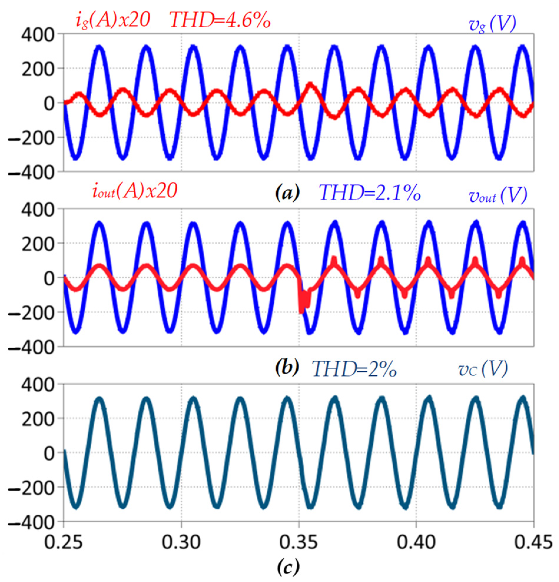
| Scenario | Parameter | THD (%) |
|---|---|---|
| linear and nonlinear load with kout = 0.0 and kc = 1.0 | Grid current ig | 4.6 |
| Output voltage vout | 2.1 | |
| Filter capacitor voltage vc | 2.0 | |
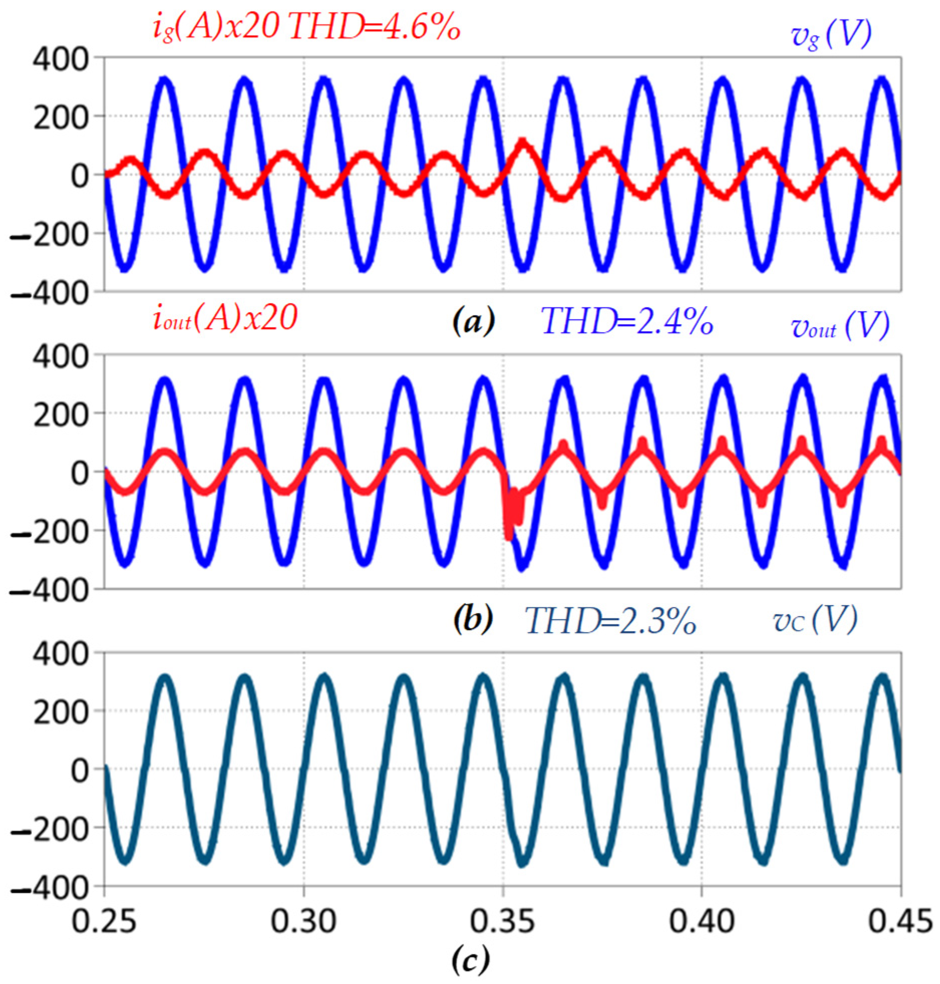
| linear and nonlinear load with kout = 1.0 and kc = 0.0 | Grid current ig | 4.6 |
| Output voltage vout | 2.4 | |
| Filter capacitor voltage vc | 2.3 | |
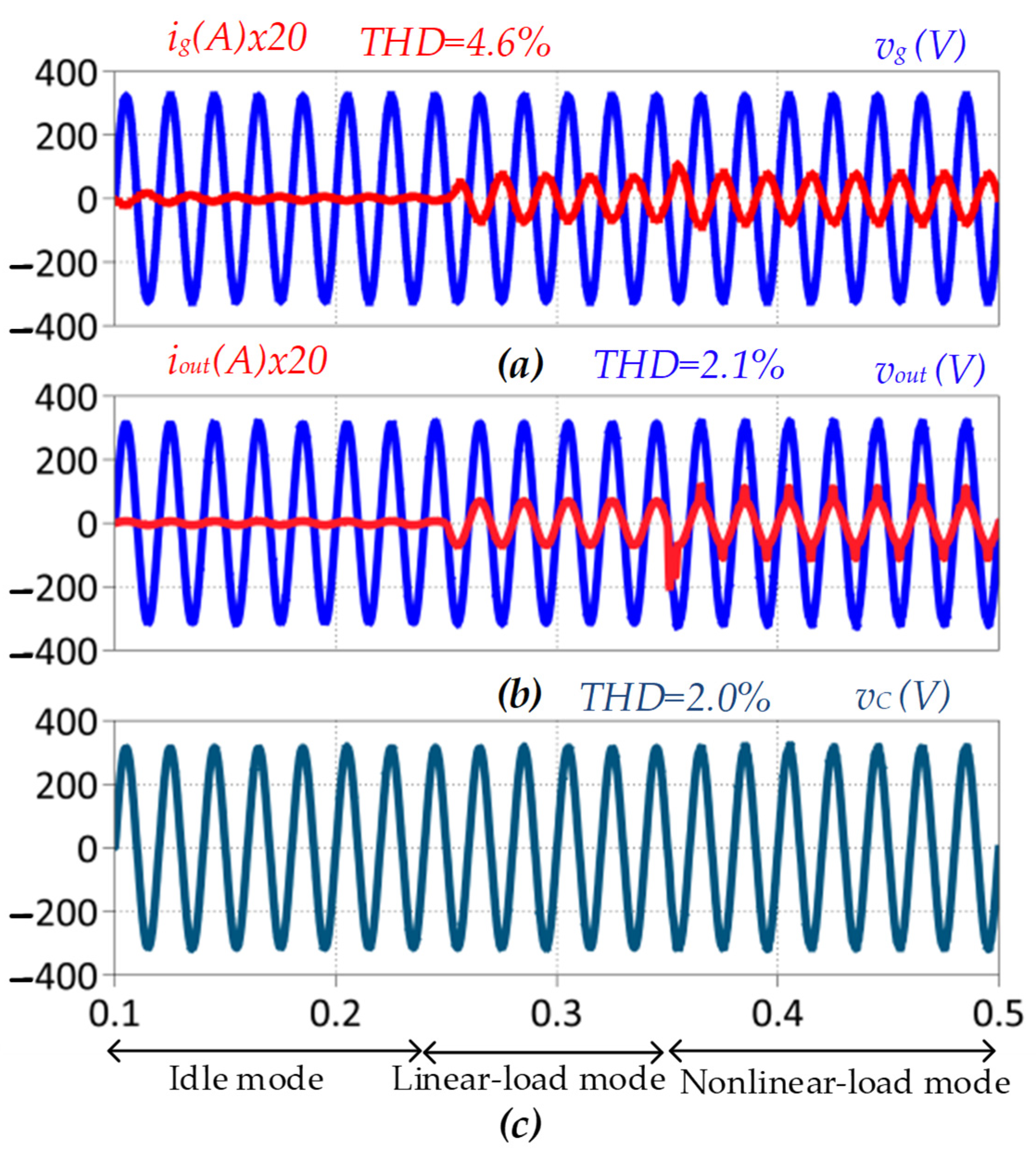
| linear and nonlinear load with kout = 0.2 and kc = 0.8 | Grid current ig | 4.6 |
| Output voltage vout | 2.1 | |
| Filter capacitor voltage vc | 2.0 | |
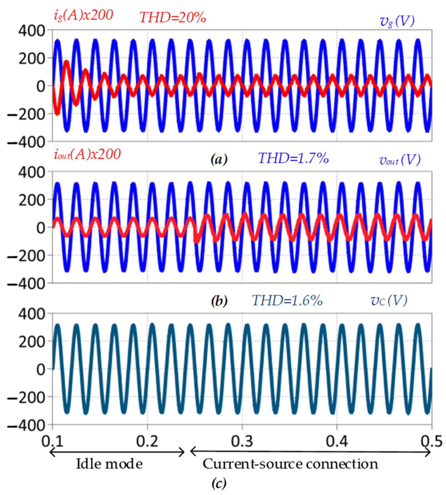
| current-source connection with kout = 0.2 and kc = 0.8 | Grid current ig | 20 |
| Output voltage vout | 1.7 | |
| Filter capacitor voltage vc | 1.6 | |
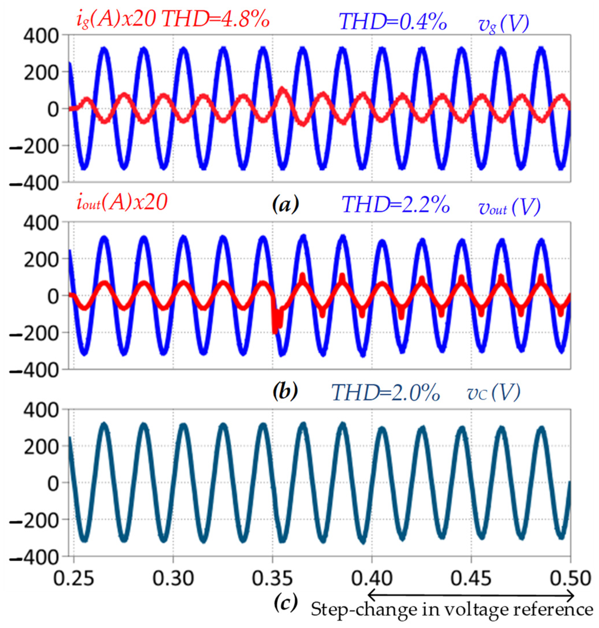
| Step change in reference from 230 V to 210 V with kout = 0.2 and kc = 0.8 | Grid current ig | 4.8 |
| Output voltage vout | 2.2 | |
| Filter capacitor voltage vc | 2.0 |
Publisher’s Note: MDPI stays neutral with regard to jurisdictional claims in published maps and institutional affiliations. |
© 2022 by the authors. Licensee MDPI, Basel, Switzerland. This article is an open access article distributed under the terms and conditions of the Creative Commons Attribution (CC BY) license (https://creativecommons.org/licenses/by/4.0/).
Share and Cite
Najafzadeh, M.; Strzelecka, N.; Husev, O.; Roasto, I.; Nassereddine, K.; Vinnikov, D.; Strzelecki, R. Grid-Forming Operation of Energy-Router Based on Model Predictive Control with Improved Dynamic Performance. Energies 2022, 15, 4010. https://doi.org/10.3390/en15114010
Najafzadeh M, Strzelecka N, Husev O, Roasto I, Nassereddine K, Vinnikov D, Strzelecki R. Grid-Forming Operation of Energy-Router Based on Model Predictive Control with Improved Dynamic Performance. Energies. 2022; 15(11):4010. https://doi.org/10.3390/en15114010
Chicago/Turabian StyleNajafzadeh, Mahdieh, Natalia Strzelecka, Oleksandr Husev, Indrek Roasto, Kawsar Nassereddine, Dmitri Vinnikov, and Ryszard Strzelecki. 2022. "Grid-Forming Operation of Energy-Router Based on Model Predictive Control with Improved Dynamic Performance" Energies 15, no. 11: 4010. https://doi.org/10.3390/en15114010
APA StyleNajafzadeh, M., Strzelecka, N., Husev, O., Roasto, I., Nassereddine, K., Vinnikov, D., & Strzelecki, R. (2022). Grid-Forming Operation of Energy-Router Based on Model Predictive Control with Improved Dynamic Performance. Energies, 15(11), 4010. https://doi.org/10.3390/en15114010