Abstract
In general, severe load imbalances in small AC micro-grid systems can degrade their operational performance and their maintenance. This is because the unbalanced load in the micro-grid affects the energy flow and the voltage regulation functions of each phase. In order to solve the voltage imbalance problem, several algorithms for the 3-phase 4-leg CVCF inverter have been proposed, but the control algorithms are not enough to operate the 4-leg CVCF inverter in a stable manner. Therefore, this paper proposes a single-phase voltage and power control algorithm for the 3-phase 4-leg CVCF inverter based on a dq control in order to improve the voltage imbalance problem caused by a severely unbalanced load, where the single phase voltage control algorithm is composed of an αβ-dq and a dq-αβ transformer, a voltage and a current controller, and an off-set controller and a PWM, and the single-phase power control algorithm is also composed of an αβ-dq and a dq-αβ transformer, an active/reactive power and a current controller, and an off-set controller and a PWM. Additionally, this paper performs modeling of the single-phase voltage and the power controller for a 4-leg CVCF inverter using the Matlab/Simulink S/W. From the simulation results, it is confirmed that the transient stability of the proposed single voltage control algorithm can be improved compared to the conventional control algorithm, and voltage control can also be maintained in a stable manner under extremely unbalanced conditions. Further, it is confirmed that 3-phase currents of the proposed single-phase power control algorithm are controlled in a stable manner under extremely unbalanced conditions.
1. Introduction
An off micro-grid system has been considered as one of the solutions for effective power supply systems for islands away from the power grid. The micro-grid system is basically composed of diesel generators, customer loads, and renewable energy such as ESS, PV, and wind turbine. However, severe load imbalances in small AC micro-grid systems can degrade their operational performance and their maintenance. This is because the unbalanced load in the micro-grid affects the energy flow and the voltage regulation functions of each phase [1,2,3,4,5]. Most customer loads are consumed in a single-phase connection, and they are also being operated under unbalanced conditions, but the inverters of PV, wind turbines, and CVCF are generally designed and operated as a balanced 3-phase system [6,7]. If the degree of imbalance for a single-phase load is worsening, the power flow of one phase could be in a state of discharging and the other phases could be charging, which may cause an unstable voltage control of the off-grid CVCF inverter. In order to solve the voltage imbalance problem, several algorithms for the 3-phase 4-leg CVCF inverter have been proposed, but the control algorithms are not enough to operate the 4-leg CVCF inverter in a stable manner [8,9,10,11,12,13,14]. Therefore, this paper proposes a single-phase voltage and power control algorithm for the 3-phase 4-leg CVCF inverter based on a dq control in order to improve the unbalanced voltage problems caused by a severely unbalanced load, where the single-phase voltage control algorithm is composed of a αβ-dq and a dq-αβ transformer, a voltage and a current controller, and an off-set controller and a PWM, and the single-phase power control algorithm is also composed of an αβ-dq and a dq-αβ transformer, an active/reactive power and a cur-rent controller, and an off-set controller and a PWM. Additionally, this paper performs modeling of the single-phase voltage and power controller for a 4-leg CVCF inverter using the Matlab/Simulink S/W. From the simulation results, it is confirmed that the transient stability of the proposed single-voltage control algorithm can be improved compared to the conventional control algorithm, and voltage control can also be maintained in a stable manner under extremely unbalanced conditions. Further, it is confirmed that 3-phase currents of the proposed single-phase power control algorithm are controlled in a stable manner under extremely unbalanced conditions.
2. Characteristics of Unbalanced Control for CVCF Inverter in Off-Grid MG System
2.1. Operation Mode of CVCF Inverter
A micro-grid system is composed of a diesel generator, a CVCF inverter, renewable energy, an ESS, and a customer load, where a CVCF inverter can be operated with the following two operation modes based on the customer load and the output of renewable energy. When the customer load is bigger than the output of renewable energy, a diesel generator performs constant voltage and constant frequency control; a CVCF inverter can be operated in a grid-connected mode as shown in Figure 1a. On the other hand, when the customer load is smaller than the output of renewable energy, the CVCF inverter performs constant voltage and constant frequency control, and the diesel generator is separated from the grid, as shown in Figure 1b.
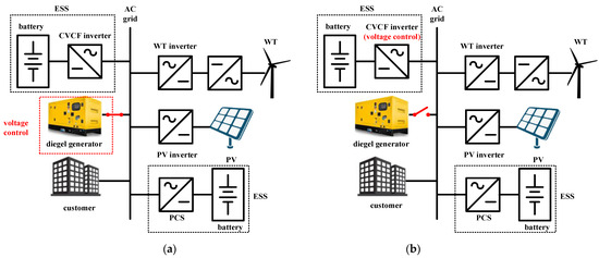
Figure 1.
Operation modes of CVCF inverter in off-grid MG systems. (a) operation mode in case I; (b) operation mode in case II.
2.2. Characteristics of Existing CVCF Inverter Control Algorithm
Generally, 3-phase CVCF inverters in an MG system have adapted a dq0 control algorithm with a PI controller based on synchronous coordination, as shown in Figure 2. This control algorithm, which adds 0-axis control from the d-q control algorithm of an existing 3-phase 3-wire CVCF inverter, generates a 0-axis signal through the abc-αβ and the αβ-dq0 transformers. Additionally, the output signals of d, q, 0-axis calculating voltages, and the current controller are converted with the dq0-αβ inverse transformers; and, they are delivered to the 3D SVPWM to control the 3-phase CVCF inverter. However, the conventional control algorithms are usually adjusted by a 3-phase controller, which cannot maintain the balanced 3-phase voltages in a stable manner because it can partially compensate for the deviation of the 3-phase voltage through a 0-axis control algorithm. In order to overcome the unbalanced load problem, the configuration and the control block diagram of a 4-leg CVCF inverter to adapt a linear/nonlinear or a balanced/unbalanced load is illustrated, as shown in Figure 2. The idea of a 4-leg CVCF inverter is to add one leg to the bridge of a conventional 3-phase 3-wire CVCF inverter to compensate for the deviation of the line-to-line voltage depending on the unbalanced load. The 4-leg CVCF inverter adopts an offset SVPWM algorithm to directly control the reference voltage of the N-phase as offset voltage, as shown in Figure 3 [15,16,17,18,19,20].
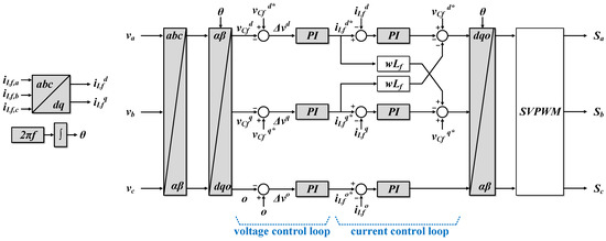
Figure 2.
Block diagram of 3-phase 3-wire CVCF inverter using dq0 control.
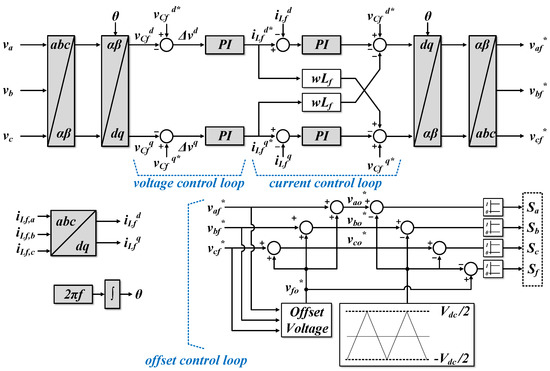
Figure 3.
Block diagram of 4-leg CVCF inverter using off-set control.
3. Single-Phase Control Algorithm for 4-Leg CVCF Inverter
The concept of a single-phase control algorithm for a 4-leg CVCF inverter is to control the 3-phase voltage and current with the control algorithm of a single-phase CVCF inverter, which maximizes the performance of the unbalanced voltage and current by controlling the phase-basis power flow and the unbalanced load. Additionally, the proposed algorithm can be classified into single-phase voltage control and into power control.
3.1. Single-Phase Voltage Control Algorithm
The proposed single-phase voltage control algorithm is composed of an αβ-dq and a dq-αβ transformer, a voltage and a current controller, and an off-set controller and a PWM, as shown in Figure 4, where in order to transform each phase voltage with an αβ-dq transformer, each phase voltage Vxα (x is to be substituted with a, b, or c) is as shown in Equation (1), each phase voltage with a 90° lagging Vxβ is as shown in Equation (2), and the transformation matrix to convert the abc coordinate with a stationary coordinate is expressed as shown in Equation (3). Therefore, based on Equations (1)–(3), the dq components of each phase voltage are obtained in Equation (4).
where Vxα is each phase voltage [V].
where Vxβ is each phase voltage with a 90° lagging [V].
where is the transformation matrix to convert the abc coordinate with a stationary coordinate.
where vCf,xd is the d component of each phase voltage, and vCf,xq is the q component of each phase voltage.
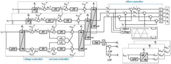
Figure 4.
Block diagram of single-phase voltage control algorithm.
On the other hand, voltage errors are calculated from the dq components of each phase voltage considering reference voltages; they create reference currents with the PI voltage controller. Additionally, current errors are calculated from each measured phase current considering reference currents, and then they create each phase current with the PI current controller. Phase currents are compared with reference currents, and then are delivered to the SPWM through the dq-αβ transformer. Therefore, the gate signals of the upper and the lower switches for each phase are integrated with the SPWM output signal and the off-set control signal.
3.2. Single-Phase Power Control Algorithm
The proposed single-phase power control algorithm is composed of an αβ-dq and a dq-αβ transformer, an active/reactive power and a current controller, and an off-set controller and a PWM, as shown in Figure 5, where in order to transform each phase current with an αβ-dq transformer, each phase current Ixα (x is to be substituted with a, b or c) is as shown in Equation (5), each phase current with a 90° lagging Ixβ is as shown in Equation (6), and the transformation matrix to convert the abc coordinate with a stationary coordinate is expressed as Equation (3). Therefore, based on Equations (3), (5), and (6), the dq components of each phase current are obtained in Equation (7). Additionally, based on Equations (4) and (7), the dq components of the active power Pxd and the reactive power Qxq are obtained as in Equations (8) and (9), respectively.
where Ixα is each phase current [A].
where Ixβ is each phase current with a 90° lagging [A].
where iLf,xd is the d component of each phase current, and iLf,xq is the q component of each phase current.
where Pxd is the d component of the active power of each phase.
where Qxq is the q component of each phase reactive power.
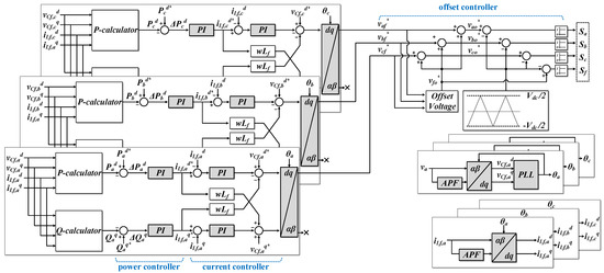
Figure 5.
Block diagram of single-phase power control algorithm.
On the other hand, power errors are calculated from the dq components of the power in each phase, considering reference powers; and, then they create reference currents with the PI power controller. Additionally, current errors are calculated from each measured phase current, considering reference currents; and then they create each phase current with the PI current controller. Phase currents are compared with reference currents, and then they are delivered to the SPWM through the dq-αβ transformer. Therefore, the gate signals of the upper and the lower switches for each phase are integrated with an SPWM output signal and an off-set control signal.
4. Modeling of Voltage and Power Controller Using Matlab/Simulink S/W
4.1. Modeling of Single-Phase Voltage Controller
Based on the Matlab/Simulink S/W, the proposed 3-phase voltage controller using three single-phase control algorithms is represented as shown in Figure 6, where the values of vCf,a, vCf,b, and vCf,c are obtained by an inverse transform to the abc frame for the outputs of each voltage controller—vCf,xd and vCf,xq (where x is a, b, and c)—which are used as switching patterns for the 4-leg in the off-set PWM block. The analog signals of measured voltages are transformed into discrete signals using ZOH (zero order hold), as expressed in Equation (10). Therefore, by combining Equations (1), (2) and (10), the dq components of each phase voltage is transformed into discrete signals, which can be obtained as shown in Equation (11).
where G(s) is the ZOH, and T is the sampling frequency.
where vCf,xd(s) is the d component of each phase voltage transformed into discrete signals [V], and vCf,xq(s) is the q component of each phase voltage transformed into discrete signals [V].
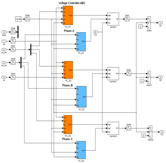
Figure 6.
Modeling of single-phase voltage controller.
4.2. Modeling of Single-phase Power Controller
Using the Matlab/Simulink S/W, the proposed 3-phase power controller with three single-phase control algorithms is represented as shown in Figure 7, where the values of iLf,a, iLf,b, and iLf,c are obtained by an inverse transform to the abc frame for the outputs of each current controller—iLf,xd and iLf,xq (where x is a, b, and c)—which are used as switching patterns for the 4-leg in the off-set PWM block. The analog signals of measured voltages are transformed into discrete signals using ZOH (zero order hold), as expressed in Equation (10). Additionally, by combining Equations (5) and (6) with Equation (10), the dq components of each phase current is transformed into discrete signals, which can be obtained as shown in Equation (12). Therefore, based on Equations (11) and (12), the dq components of the active and reactive power in each phase is transformed into discrete signals, which can be obtained as shown in Equations (13) and (14).
where iLf,xd(s) is the d component of each phase current transformed into discrete signals [V], and iLf,xq(s) is the q component of each phase current transformed into discrete signals [V].
where Pxd(s) is the d component of each phase active power transformed into discrete signals [W].
where Qxq(s) is the q component of the reactive power of each phase transformed into discrete signals [var].
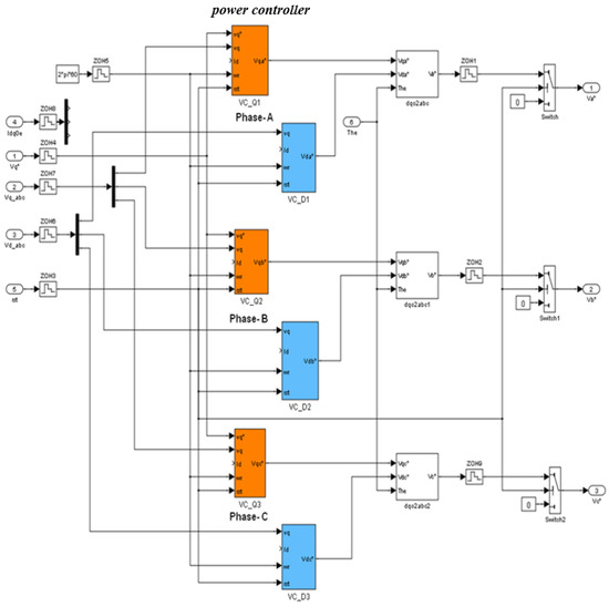
Figure 7.
Modeling of single-phase power controller.
5. Case Studies
5.1. Simulation Conditions
In order to evaluate the operation characteristics of the presented single-phase voltage and power controller, the simulation conditions are assumed as in Figure 8 and Figure 9, where the simulation conditions adapt the system parameter of the demonstration projects for the micro-grid system. Figure 8 shows the stand-alone mode of an off-grid MG, which is composed of a CVCF inverter, a PV inverter, and customer loads, where if the 3-phase PV inverter supplies 3-phase balanced power by an MPPT operation and the customer load is in an unbalanced condition, the CVCF inverter may be in an extremely unbalanced condition—suppling power at two phases and consuming power at one phase, as shown in Figure 8.
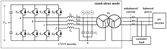
Figure 8.
Operation condition of stand-alone mode.
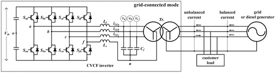
Figure 9.
Operation condition of grid-connected mode.
Figure 9 shows the grid-connected mode of an off-grid MG, which is composed of a diesel generator, a CVCF inverter, and customer loads, where the CVCF inverter is operated in a grid-connected mode. If the 3-phase diesel generator supplies 3-phase balanced power and the customer load is in an unbalanced condition, the CVCF inverter may be in an extremely unbalanced condition—suppling power at two phases and consuming power at one phase, as shown in Figure 9.
Furthermore, the customer loads in Figure 8 and Figure 9 are assumed as single-phase or 3-phase 4-wire R loads, the DC input voltage of the 4-leg CVCF inverter is 700 V, and the switching and sampling frequencies are 10 kHz, respectively. Additionally, the reference voltage of the CVCF inverter in standard mode (va, vb, vc) is assumed as 311 V, and the reference power of the CVCF inverter in grid-connected mode (Pa, Pb, Pc) is 6.2 kW. Further, the unbalanced factors of the CVCF inverter in standard mode are assumed at 42.9% and 28.6%, respectively, the unbalanced factors of the CVCF inverter in grid-connected mode is 60%, and the detailed system parameters are expressed as shown in Table 1 [21].

Table 1.
System parameter.
5.2. Characteristic of Single-Phase Voltage Control
Based on the simulation conditions in Figure 8, the performances of the proposed single-phase voltage control algorithm and the conventional 3-phase dq0 control algorithm are demonstrated as shown in Figure 10 and Figure 11, where Figure 10a and Figure 11a are phases of the output voltage and Figure 10b and Figure 11b are the current of the customer load, Figure 10c and Figure 11c are the dq0 component of the grid voltage, and Figure 10d and Figure 11d are the dq0 components of the current of customer load. Additionally, as shown in Figure 11c, the d and the q components of the proposed control algorithm are properly maintained as 311 V and 0 for the 75/50/50Apeak and the 80/70/60Apeak unbalanced conditions, respectively. Therefore, this paper assumes four different operation conditions, which are 60Apeak balanced load, 75/50/50Apeak unbalanced load, 100Apeak balanced load, and 80/70/60Apeak unbalanced condition, as shown in Figure 10 and Figure 11. As shown in Figure 10, the 3-phase grid voltages of the conventional 3-phase dq0 control algorithm are maintained in a stable manner for the 75/50/50Apeak and the 80/70/60Apeak unbalanced condition, but the values of the d component at each phase voltage drop significantly to 106 V at t3 time interval.
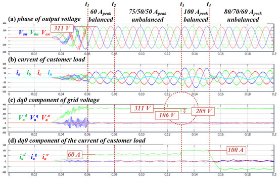
Figure 10.
Performance of conventional 3-phase dq0 control.
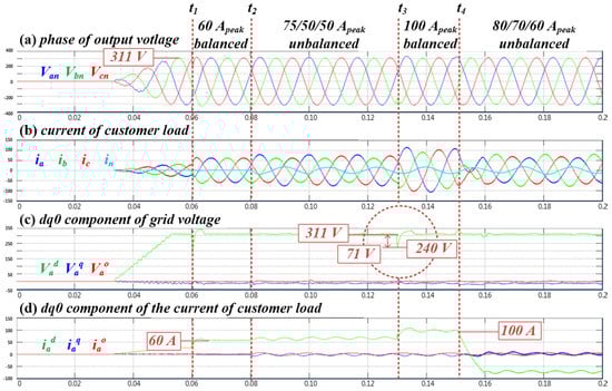
Figure 11.
Performance of single-phase voltage control algorithm.
Furthermore, as shown in Figure 11c, the d and the q components of the proposed control algorithm are properly maintained as 311 V and 0 for the 75/50/50Apeak and the 80/70/60Apeak unbalanced conditions, respectively. Additionally, it is clear that the 3-phase grid voltages of the proposed single-phase voltage algorithm are maintained in a stable manner for the unbalanced conditions, and the values of the d component at each phase voltage drops to 71 V, as shown in Figure 11. Therefore, by comparing the proposed algorithm in Figure 11 with the conventional algorithm in Figure 10, it is confirmed that the transient stability of the proposed algorithm can be improved, and voltage control can also be maintained in a stable manner under extremely unbalanced conditions.
5.3. Characteristics of Single-Phase Power Control
Based on the simulation conditions in Figure 9, the performances of the proposed single-phase power control algorithm are demonstrated as shown in Figure 12, where Figure 12a is each phase current of the CVCF inverter, Figure 12b is the d-component of each phase current, and Figure 12c is the q-component of each phase current. Additionally, this paper adapts two different operation scenarios, which are the −40Apeak balanced load and the −40/−40/20Apeak unbalanced load, as shown in Figure 12. From the simulation results, it is clear that the d-components of each phase current are controlled from −40/−40/−40Apeak to −40/−40/20Apeak, as shown in Figure 12b; and, the q-components of each phase current are maintained at 0, as shown in Figure 12c. Therefore, it is confirmed that 3-phase currents of the proposed single-phase power control algorithm are controlled in a stable manner under extremely unbalanced conditions.
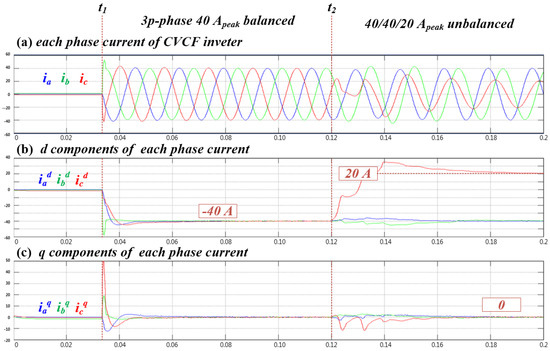
Figure 12.
Performance of a single-phase power control algorithm.
6. Conclusions
In order to overcome the voltage unbalance problem of the off-grid micro-grid system, this paper has proposed a single-phase voltage and power control algorithm for the 4-leg CVCF inverter. The main results of this paper are summarized as follows.
- (1)
- The conventional control algorithms are usually adjusted by a 3-phase controller, which cannot maintain the balanced 3-phase voltages in a stable manner because it can partially compensate for the deviation of the 3-phase voltage through a 0-axis control algorithm.
- (2)
- From the simulation results, it is confirmed that the values of the d component at each phase voltage drop significantly to 106 V in a conventional 3-phase dq0 control algorithm, but the 3-phase grid voltages of the proposed single-phase voltage algorithm are maintained in a stable manner for the unbalanced conditions, and the values of the d component at each phase voltage drop to 71 V. From the simulation results, it is confirmed that the transient stability of the proposed single voltage control algorithm can be improved compared to the conventional control algorithm, and voltage control can also be maintained in a stable manner under extremely unbalanced conditions.
- (3)
- Additionally, it is clear that the d-components of each phase current are controlled from −40/−40/−40Apeak to −40/−40/20Apeak, and the q-components of each phase current are maintained at 0. Therefore, it is confirmed that 3-phase currents of the proposed single-phase power control algorithm are controlled in a stable manner under extremely unbalanced conditions.
- (4)
- Furthermore, the single voltage and power control algorithm can control voltage and power under different conditions if the CVCF inverter is designed according to capacity, and it will be studied in a large-scale micro-grid system in the future.
Author Contributions
All of the authors contributed to publishing this paper. B.-G.H. and D.-S.R. carried out modeling, simulations, and they compiled the manuscript. The literature review and the simulation analysis were performed by J.-M.K., K.-H.K. and J.S., who also collected the data and investigated early works. All authors have read and agreed to the published version of the manuscript.
Funding
This research received no external funding.
Institutional Review Board Statement
Not applicable.
Informed Consent Statement
Not applicable.
Data Availability Statement
Not applicable.
Acknowledgments
This work was supported by the Power Generation and Electricity Delivery Core Technology program of the Korea Institute of Energy Technology Evaluation and Planning (KETEP), with financial resources from the Ministry of Trade, Industry and Energy, Republic of Korea (No. 20214910100010, 20213030160080).
Conflicts of Interest
The authors declare no conflict of interest.
References
- Kwasinski, A. Technology Planning for Electric Power Supply in Critical Events Considering a Bulk Grid, Backup Power Plants, and Micro-Grids. IEEE Syst. J. 2010, 4, 167–178. [Google Scholar] [CrossRef]
- International Electrotechnical Commissions. Microgrids for Disaster Preparedness and Recovery: With Electricity Continuity Plans and Systems; International Electrotechnical Commissions: Geneva, Switzerland, 2014; pp. 41–45. [Google Scholar]
- Yuan, M.; Fu, Y.; Mi, Y.; LI, Z.; Wang, C. The Coordinated Control of Wind-Diesel Hybrid Micro-Grid Based on Sliding Mode Method and Load Estimation. IEEE Access 2018, 6, 76867–76875. [Google Scholar] [CrossRef]
- Garcia Vera, Y.E.; Dufo-Lopez, R.; Bernal-Austin, J.L. Energy Management in Microgrids with Renewable Energy Sources: A Literature Review. Appl. Sci. 2019, 9, 3854. [Google Scholar] [CrossRef] [Green Version]
- Liu, Y.; Wang, X.; Wang, S. Research on Frequency Control of Islanded Microgrid with Multiple Distributed Power Sources. Processes 2020, 8, 193. [Google Scholar] [CrossRef] [Green Version]
- Lee, H.D.; Choi, S.S.; Nam, Y.H.; Son, J.H.; Rho, D.S. A study on the transient operation algorithm in micro-grid based on CVCF inverter. J. Korea Acad.-Ind. Coop. Soc. 2018, 19, 526–535. [Google Scholar]
- Lee, H.; Choi, S.; Ferreira, M.; Park, J.; Rho, D. A Study on Transient Operation Characteristics of 30kW Scale CVCF Inverter based Micro-grid. J. Korea Acad.-Ind. 2019, 20, 18–25. [Google Scholar]
- Demirkutlu, E.; Cetinkaya, S.; Hava, A.M. Output Voltage Control of A Four-Leg Inverter Based Three-Phase UPS by Means of Stationary Frame Resonant Filter Banks. In Proceedings of the 2007 IEEE International Electric Machines and Drives Conference, Antalya, Turkey, 3–5 May 2007. [Google Scholar]
- Heredero-Peris, D.; Chillon-Anton, C.; Pages-Gimenez, M.; Gross, G.; Montesinos-Miracle, D. Implementation of grid-connected to/from off-grid transference for micro-grid inverters. In Proceedings of the IECON 2013—39th Annual Conference of the IEEE Industrial Electronics Society, Vienna, Austria, 10–13 November 2013. [Google Scholar]
- Mivejh, M.R.; Rahmat, M.F.; Ghadimi, A.A.; Mustafa, M.W. Control techniques for three-phase four-leg voltage source inverters in autonomous microgrids: Areview. Renew. Sustain. Energy Rev. 2016, 54, 1592–1610. [Google Scholar] [CrossRef]
- Choi, S.; Kang, M.; Lee, H.; Nam, Y.; Rho, D. A Stable Operation Strategy in Micro-grid Systems without Diesel Generators. J. Electr. Eng. Technol. 2018, 13, 114–123. [Google Scholar]
- Olives-Camps, J.C.; Mauricio, J.M.; Villarejo, M.B.; Matas-Díaz, F.J. Voltage Control of Four-Leg VSC for Power System Applications With Nonlinear and Unbalanced Loads. IEEE Trans. Energy Convers. 2020, 35, 640–650. [Google Scholar] [CrossRef] [Green Version]
- Zhou, J.; Sun, H.; Xu, Y.; Han, R.; Yi, Z.; Wang, L.; Guerrero, J.M. Distributed Power Sharing Control for Islanded Single-/Three-Phase Microgrids With Admissible Voltage and Energy Storage Constraints. IEEE Trans. Smart Grid 2021, 12, 2760–2775. [Google Scholar] [CrossRef]
- Shuang, L.; Yu, Y.; Wenkang, Y.; Lichao, X. Single-step model predictive control of VSC converter station supplying power to passive network. In Proceedings of the 2021 4th International Conference on Advanced Electronic Materials, Computers and Software Engineering (AEMCSE), Changsha, China, 26–28 March 2021. [Google Scholar]
- Zhang, R.; Prasad, V.H.; Boroyevich, D.; Lee, F.C. Three-Dimensional Space Vector Modulation for Four-Leg Voltage-Source Converters. IEEE Trans. Power Electron. 2002, 17, 314–326. [Google Scholar] [CrossRef]
- Kim, J.; Sul, S. A Carrier-Based PWM Method for Three-Phase Four-Leg Voltage Source Converters. IEEE Trans. Power Electron. 2004, 19, 66–75. [Google Scholar]
- Kim, J.; Sul, S. A Carrier-Based PWM Method with Optimal Switching Sequence for a Multilevel Four-Leg Voltage-Source Inverter. IEEE Trans. Power Electron. 2008, 44, 1239–1248. [Google Scholar] [CrossRef]
- Demirkutlu, E.; Hava, A.M. A Scalar Resonant-Filter-Bank-Based Output-Voltage Control Method and a Scalar Minimum-Switching-Loss Discontinuous PWM Method for the Four-Leg-Inverter-Based Three-Phase Four-Wire Power Supply. IEEE Trans. Ind. Appl. 2009, 45, 982–991. [Google Scholar] [CrossRef]
- Kim, S.; Park, J.; Tae, D.; Kim, S.; Song, J. Rho, D.; A Study on the Algorithm for Single Phase Control of IGBT PWM Rectifier. J. Korea Acad.-Ind. 2016, 17, 26–33. [Google Scholar]
- Kim, S.; Choi, S.; Kim, S.; Rho, D. Single-phase Control Algorithm of 4-Leg type PCS for Micro-grid System. J. Korea Acad.-Ind. 2017, 18, 817–825. [Google Scholar]
- Kim, J.; Park, Y.; LEE, E. The Comparison Study for Voltage, Current and Load Unbalance Factor. Trans. Korean Inst. Electr. Eng. 2005, 54, 88–93. [Google Scholar]
Publisher’s Note: MDPI stays neutral with regard to jurisdictional claims in published maps and institutional affiliations. |
© 2022 by the authors. Licensee MDPI, Basel, Switzerland. This article is an open access article distributed under the terms and conditions of the Creative Commons Attribution (CC BY) license (https://creativecommons.org/licenses/by/4.0/).