
Experimental Investigation of Possibilities to Improve Filtration Efficiency of Tangential Inlet Return Cyclones by Modification of Their Design


Abstract
:1. Introduction

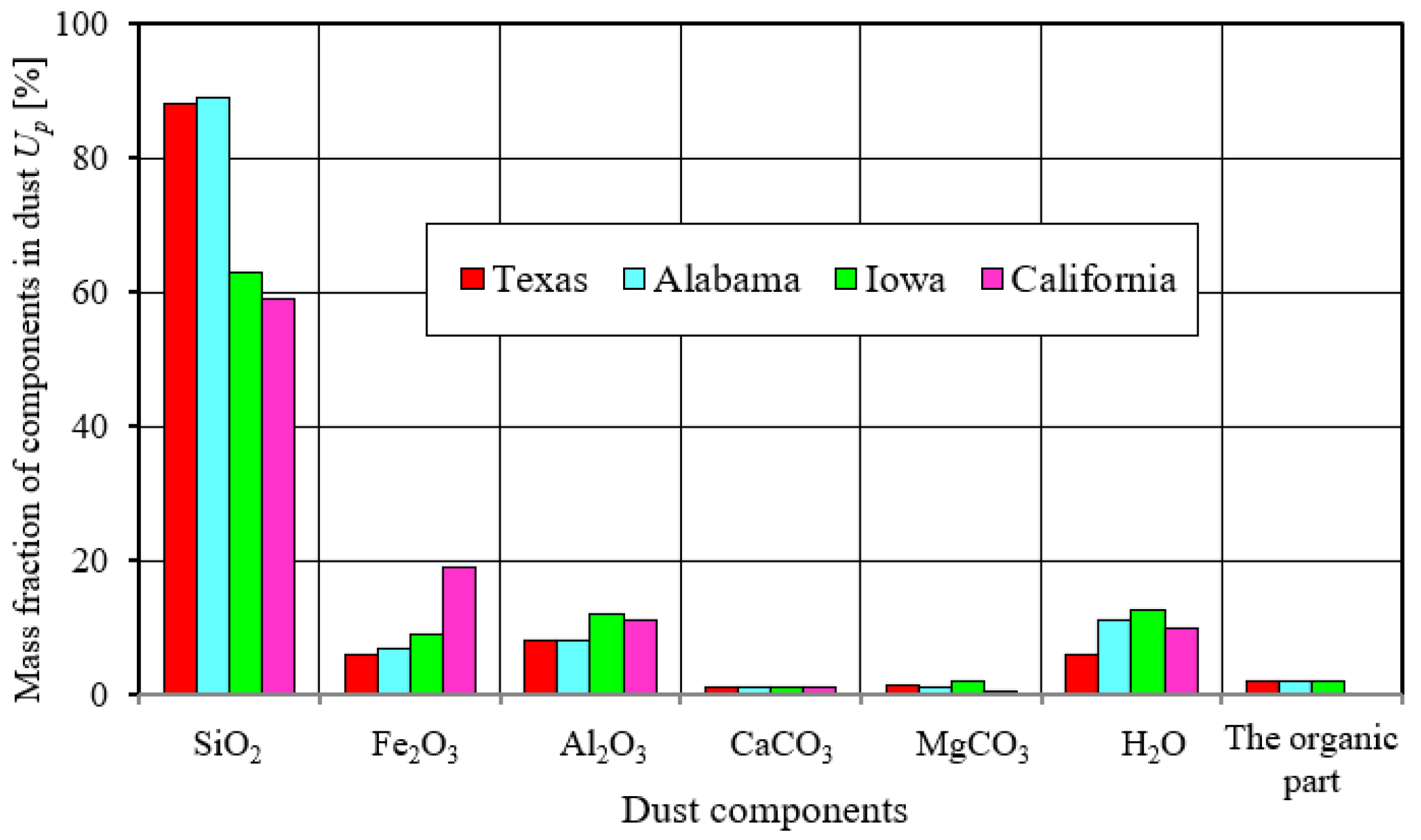
| Author | Ambient Conditions | Value [g/m3] |
|---|---|---|
| [1,2] | Clean rural environments | from 0.01 mg/m3 |
| Movement of a column of tracked vehicles in desert conditions | about 20 | |
| [3] | Dusty environments | 0.001–10 |
| [22] | On highways | 0.0004–0.1 |
| [22] | When driving a column of vehicles on sandy terrain | up to 0.03–8 |
| [23] | During takeoff or landing of a helicopter on an adventure landing site at helicopter propeller tip height—0.5 m above ground | 3.33 |
| [24] | Limited visibility | 0.6–0.7 |
| Zero visibility | about 1.5 | |
| [4] | At a distance of several meters behind a column traveling at 30 km/h: | |
| 1.17 | |
| 0.62 | |
| 0.18 | |
| [5] | A tracked vehicle driving on sandy terrain at 18 km/h: | |
| 2.1–3.8 | |
| 0.8–1 | |
| [11] | A few meters away from the sand road on which the terrain vehicles were moving | 0.05–10 |
| [1,3,11] | At the inlet to the combustion engine intake system of a vehicle | not more than 2.5 |
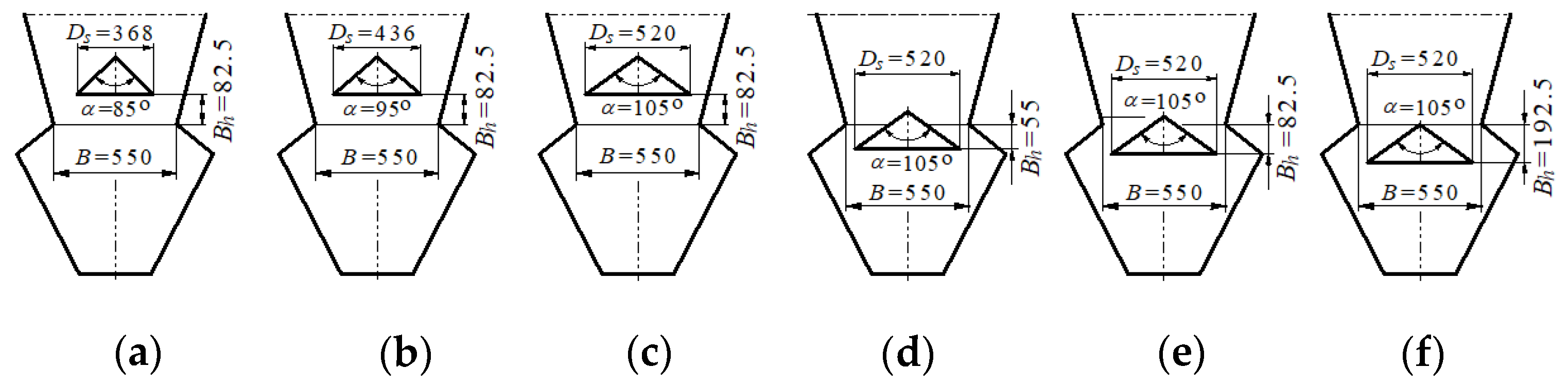
2. Analysis of Options for Increasing the Separation Efficiency of Tangential Inlet Return Cyclones
- (1)
- (2)
- (3)
- (1)
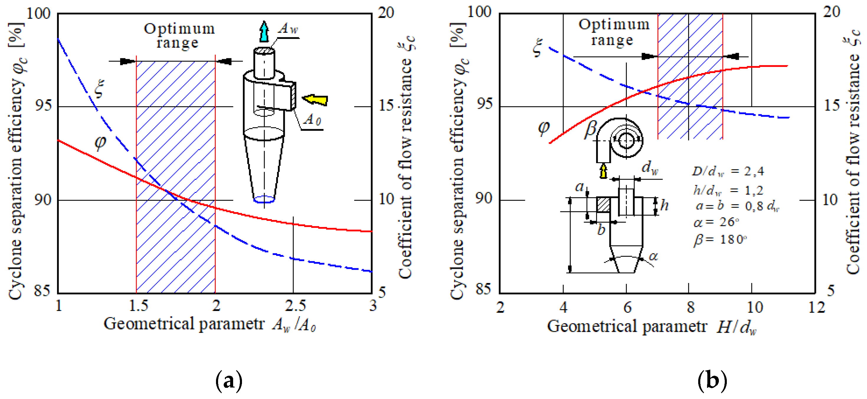
- It is possible to improve cyclone performance in terms of reducing pressure drop or increasing separation efficiency by modifying its design without changing its main dimensions.
- (2)
- The modifications of cyclones presented in the literature have been performed in single cyclones and tested mainly towards their use for industrial purposes.
- (3)
- There are no proposals for modifications of cyclones applicable to motor vehicle air filters.
- (4)
- The following solutions can be used to modify cyclones that are elements of a multicyclone constituting the first stage of a motor vehicle air filter:
- Changing the cross-sectional geometry and shape of the inlet stub;
- Changing the shape of the outlet duct (outlet tube);
- Use of a streamlined shape of the inlet opening to the outlet duct.
3. Experimental Research on the Influence of the Modification of the Design of the Tangential Inlet Reversible Cyclone on the Improvement of Separation Efficiency
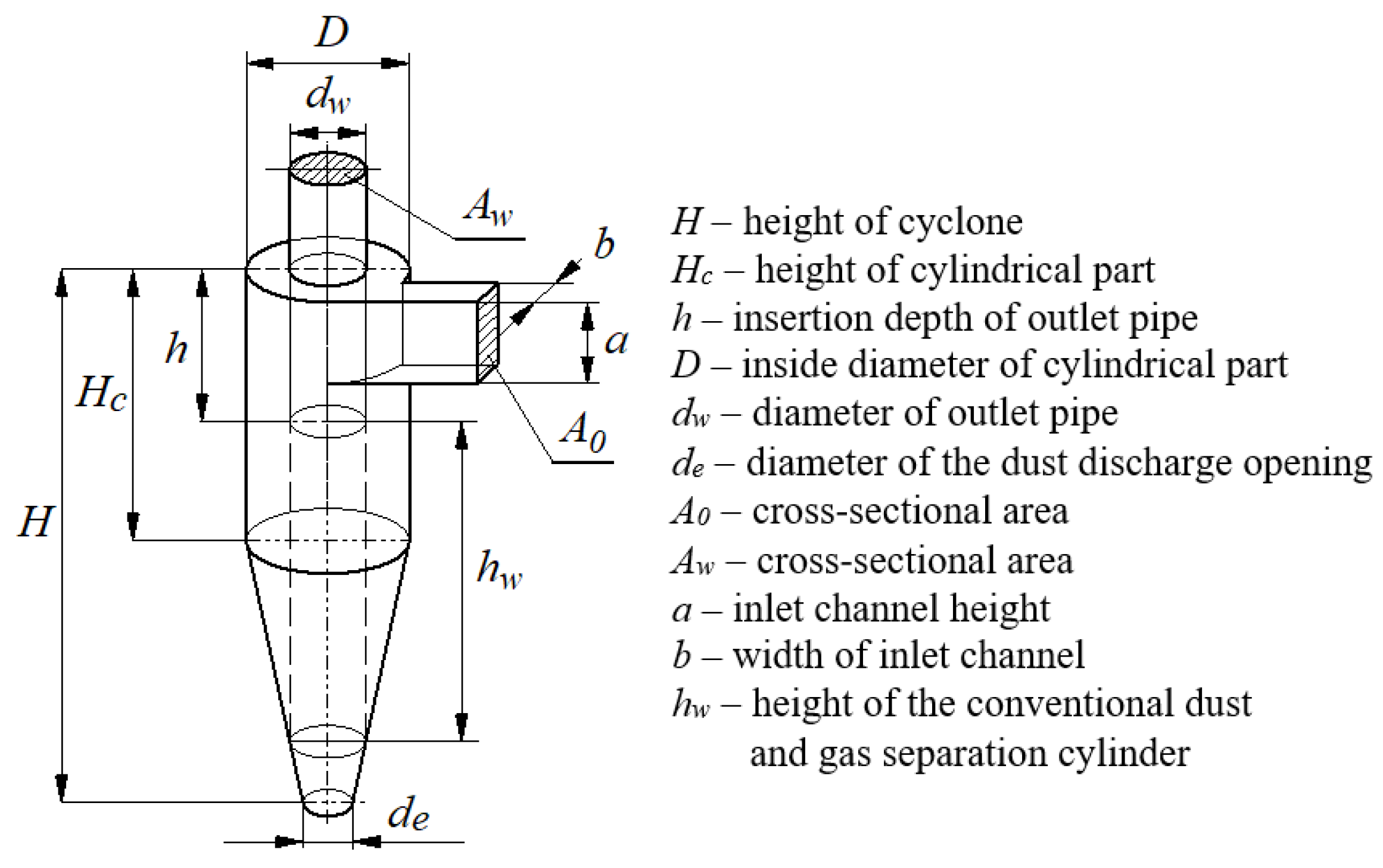
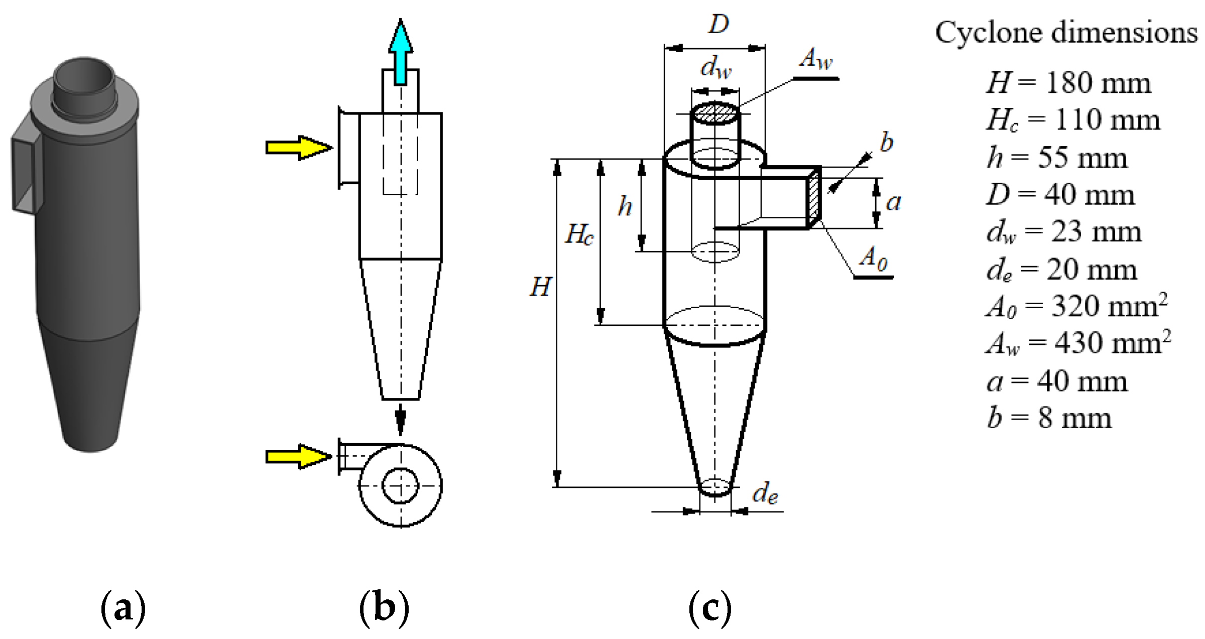
3.1. Object of Research
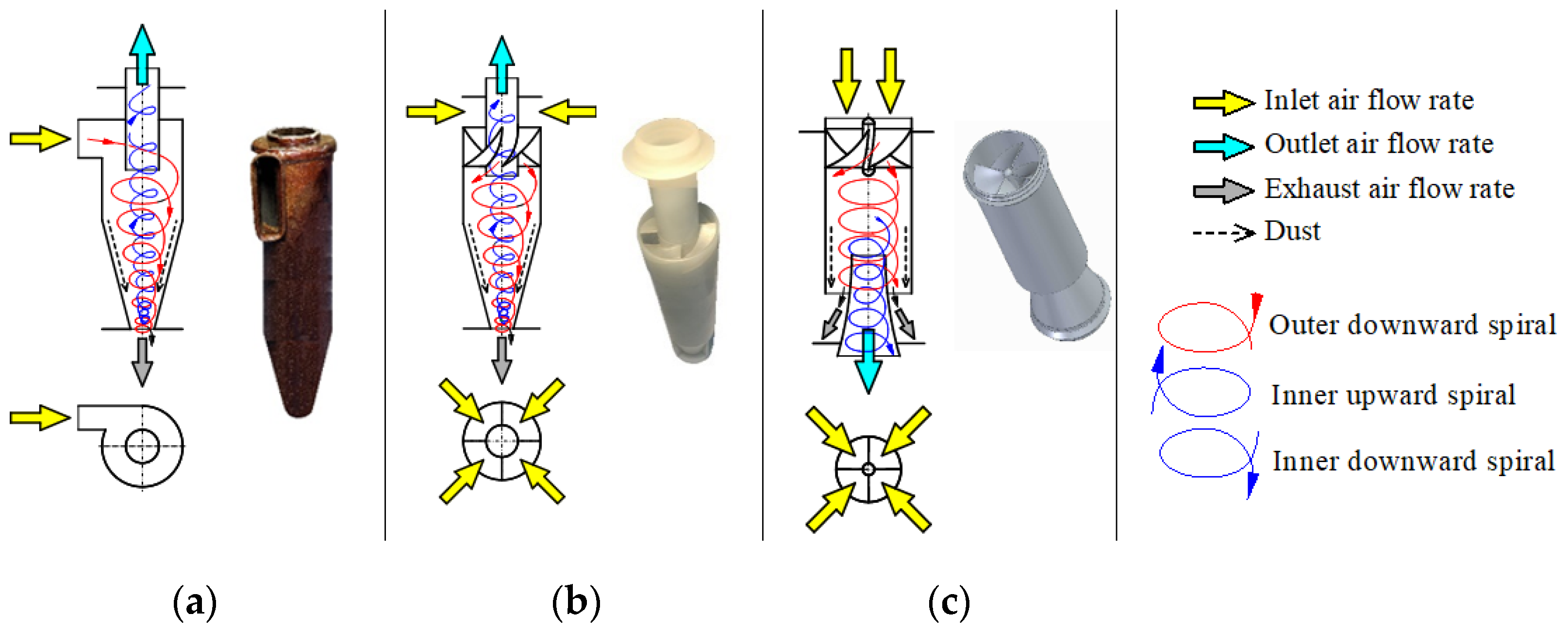
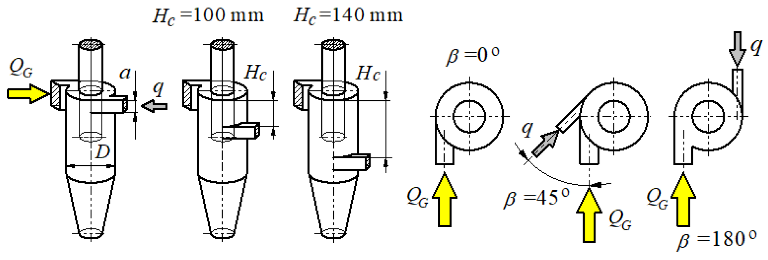
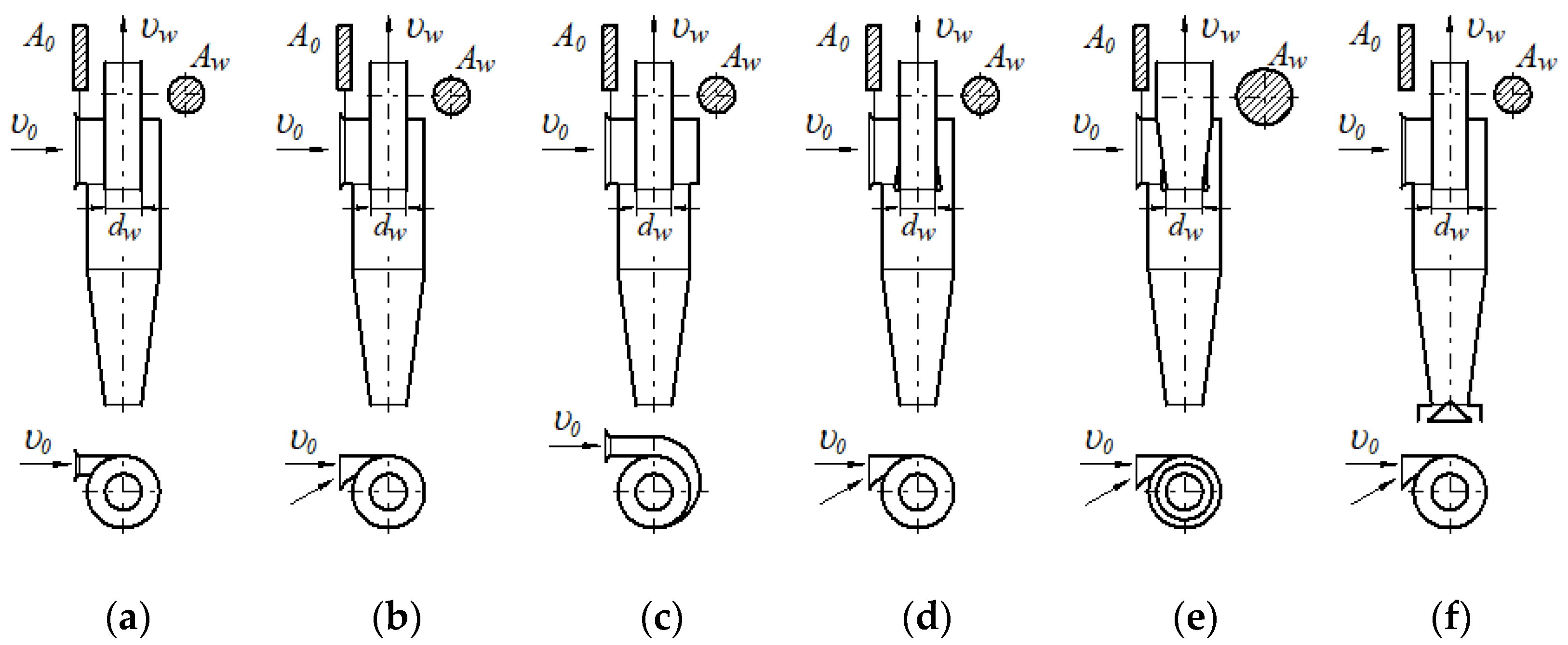
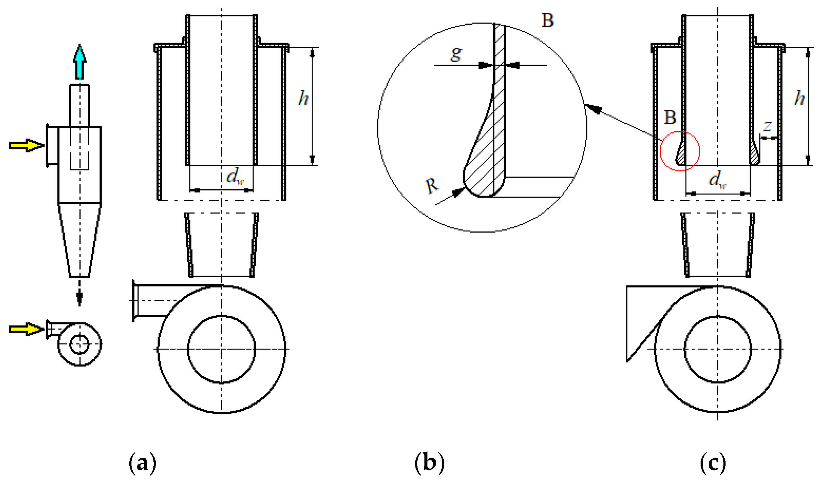
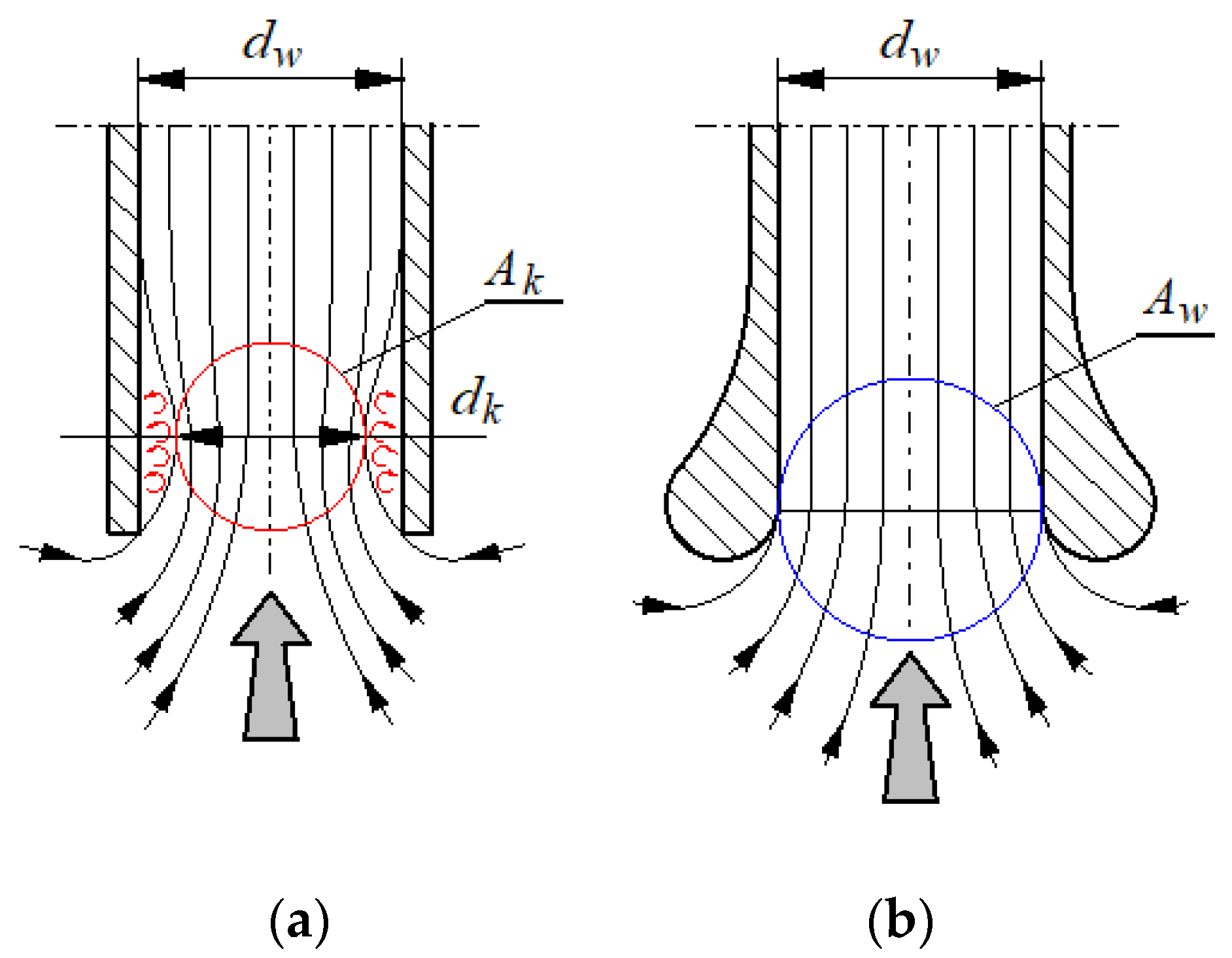
3.2. Proposal for Modification of D-40 Cyclone Design
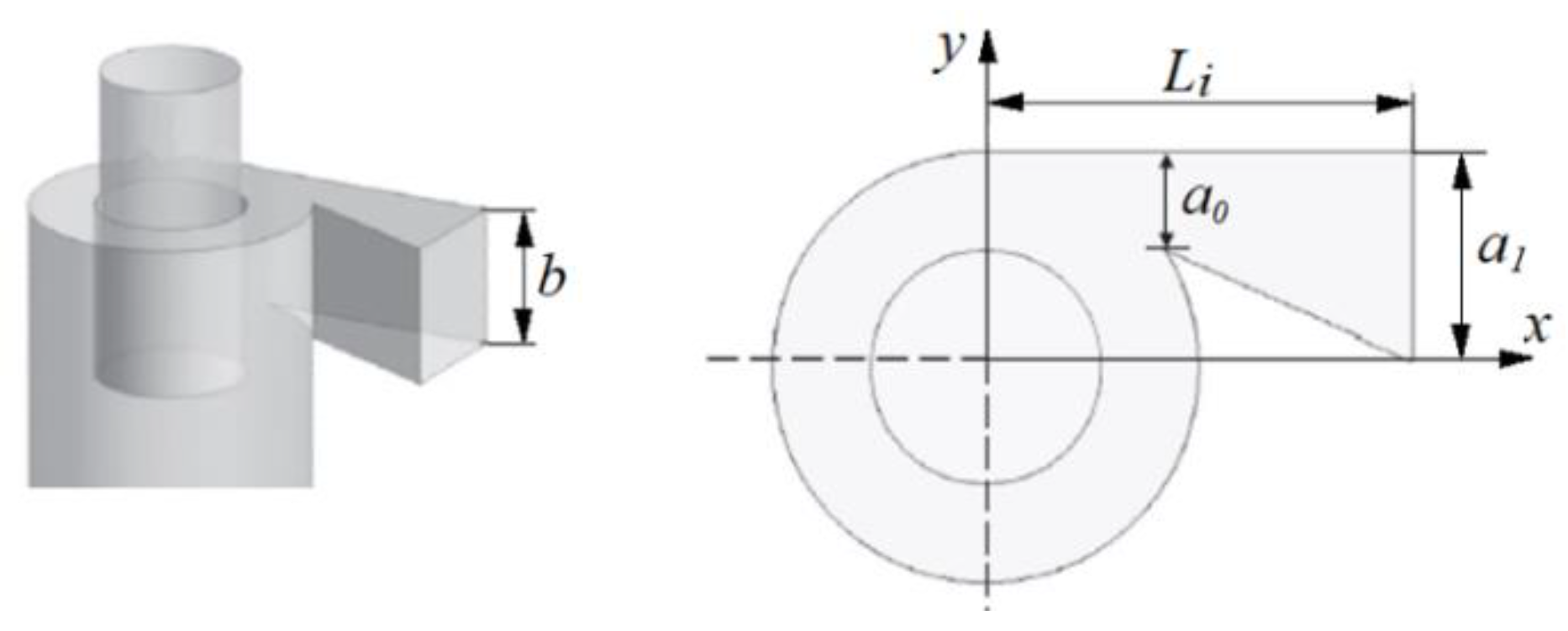
- A
- An asymmetrical shape of the inlet spigot was used instead of a symmetrical one, while maintaining the previous size and shape of its cross-section at the inlet to the cylindrical part (Figure 24);
- B
- A streamlined shape was given to the edges of the inlet opening of the outlet tube (Figure 25);
- C
- A tapered outlet tube was used (Figure 26).
- Version W1—modification element A;
- Version W2—elements of modification A + B;
- Version W3—elements of modification A + B + C.
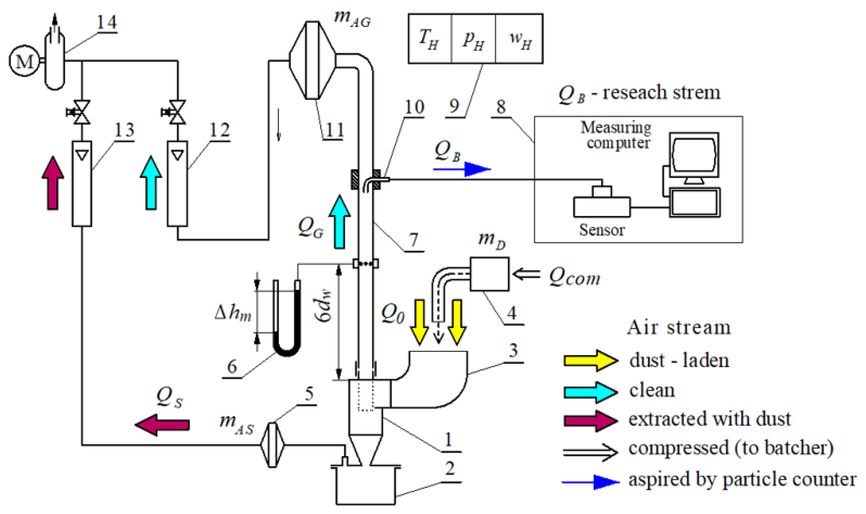
3.3. Experimental Testing of Cyclones
- Separation efficiency φc = f(QG);
- Pressure drop Δpc = f(QG).
- Filtration accuracy dzmax = f(QG).
3.3.1. Methodology and Test Conditions
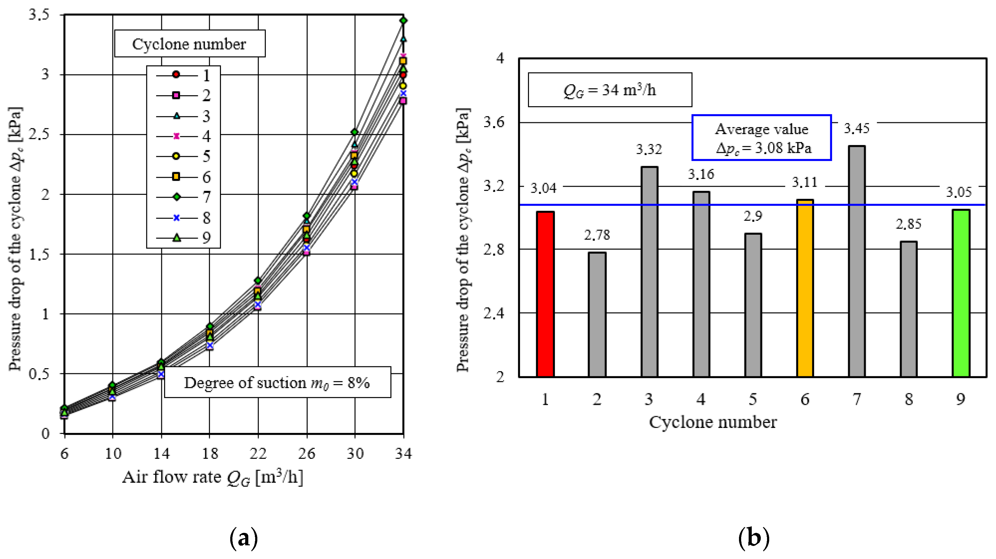
3.3.2. Analysis of Test Results of Original Version Cyclones
3.3.3. Analysis of Test Results of Cyclones with Modifications
4. Conclusions
- (1)
- Although there are many structural possibilities of increasing the effectiveness of cyclones, not all solutions, due to their too complicated construction, can be used in cyclones used in motor vehicle engine inlet air filters. The effect in the form of an increase in separation efficiency or a decrease in flow resistance may be disproportionally small in relation to the costs incurred.
- (2)
- To modify the cyclones, which are the elements of the multicyclone of the motor vehicle air filter, the following solutions can be used practically: change of the shape of the inlet port—replacement of the symmetric inlet with an asymmetric one, introduction of a streamlined shape of the inlet opening of the outlet duct and change of the shape of the outlet duct (outlet tube) from cylindrical to conical. It may be technologically difficult to make a streamlined shape of the outlet tube inlet opening.
- (3)
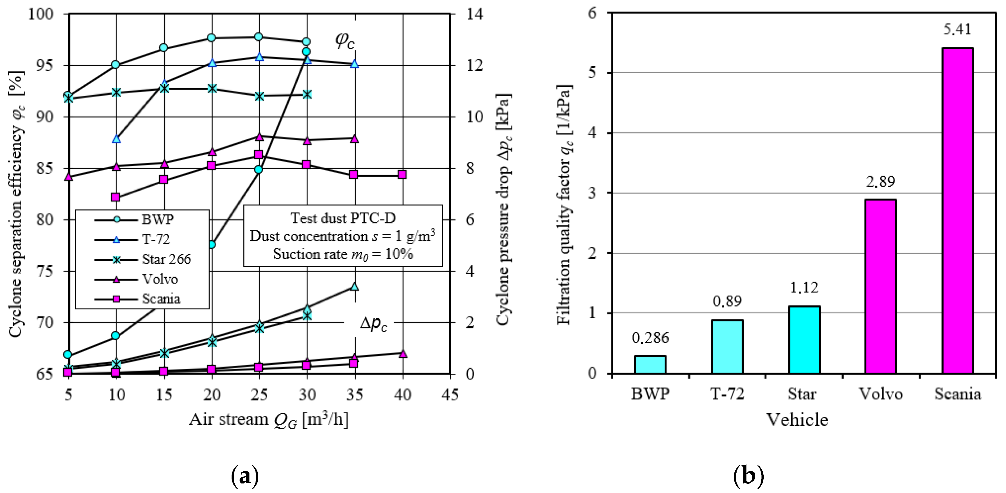
- The separation efficiency of the tested cyclones (reciprocating cyclones with tangential inlet) with respect to polydisperse dust with grain size up to dpmax = 80 µm increases with the increase of air flow QG (inlet velocity 0) up to the value of φcmax = 94.8%, and then slightly decreases. Such a character of the course of φc = f(QG) and the values of the obtained efficiencies are consistent with the information provided in the literature by the authors of research papers.
- (4)
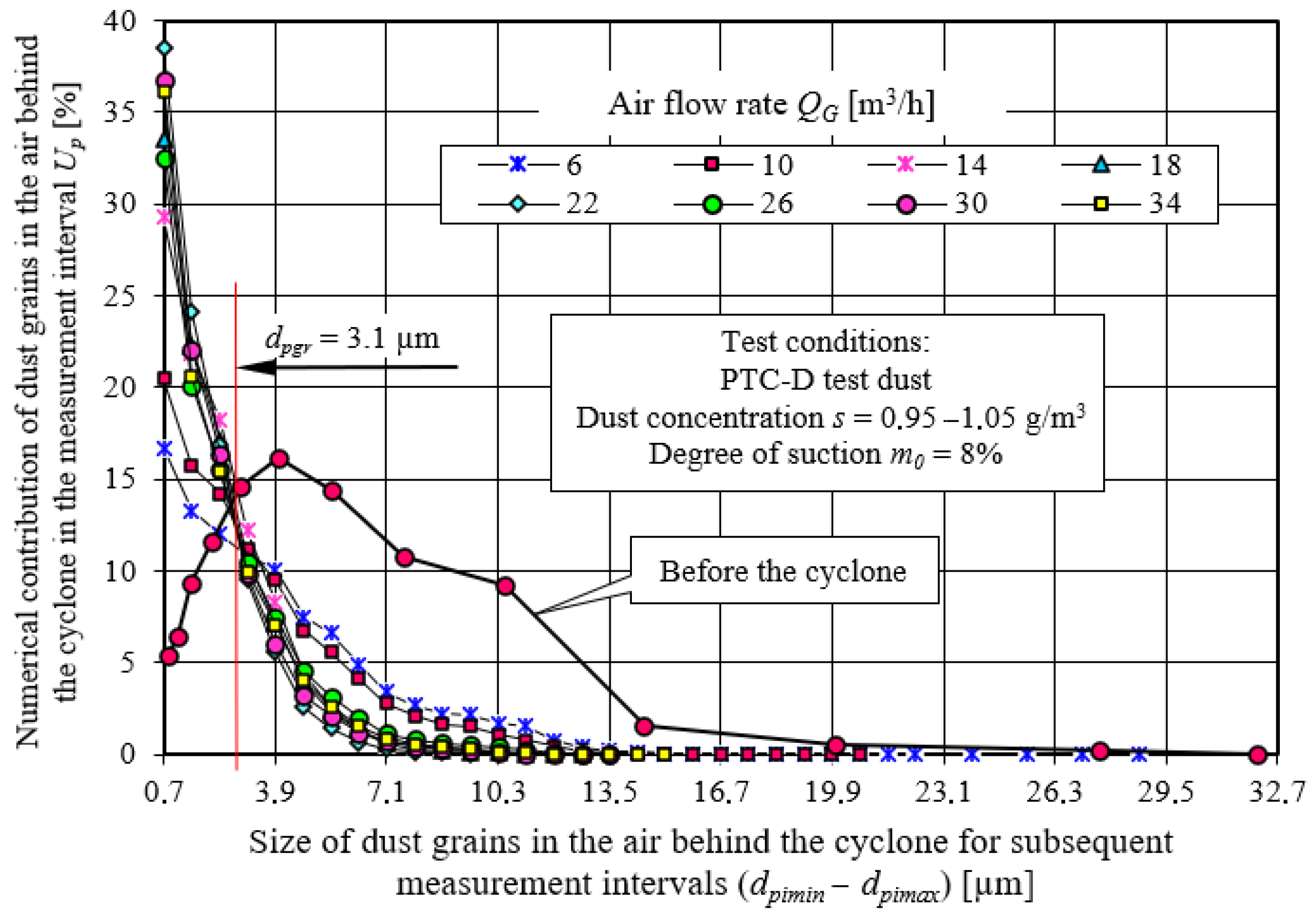
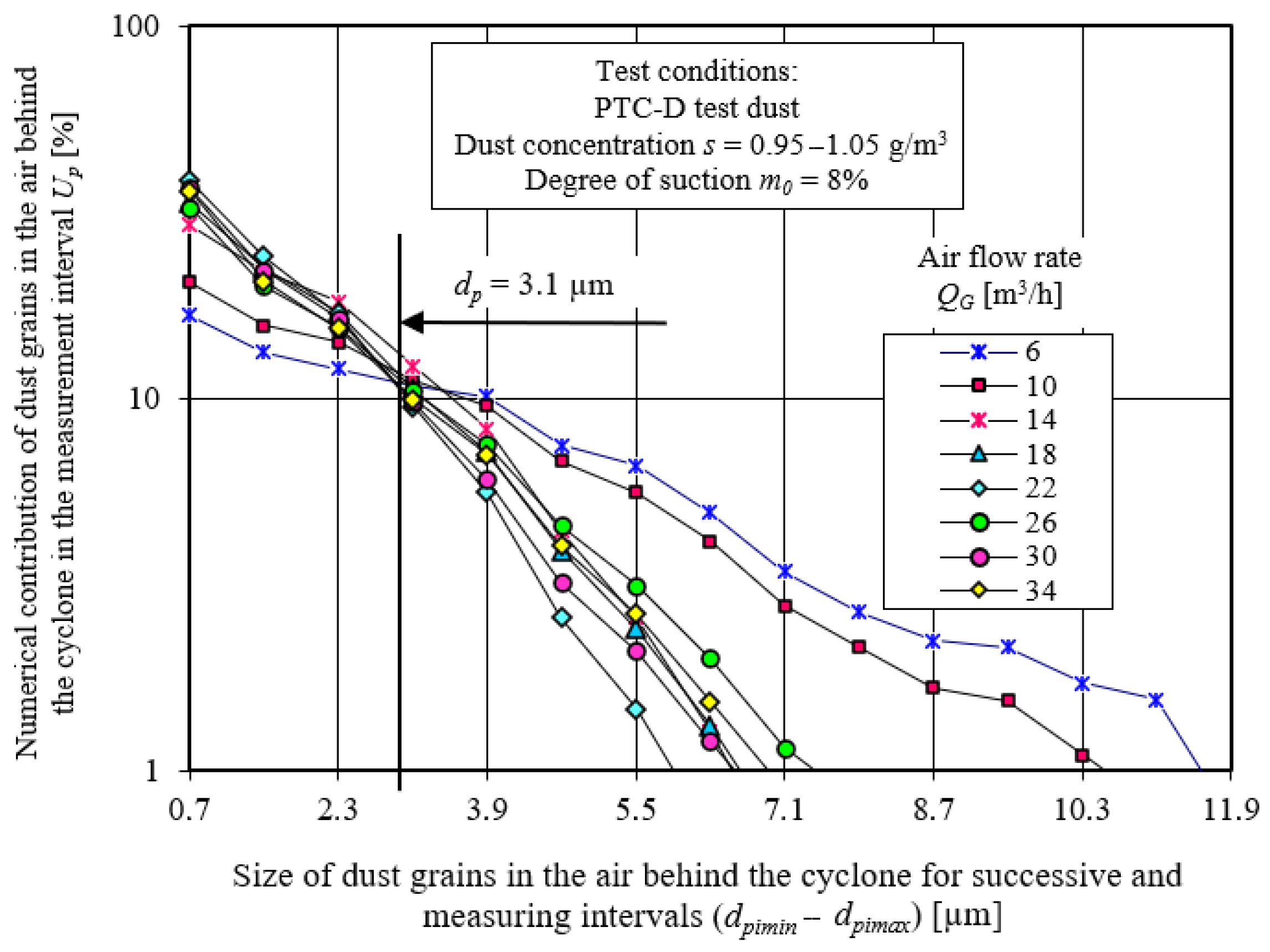
- For steady flow conditions (QG = const.), the number of dust grains in the air behind the cyclone systematically decreases as their size increases until they disappear completely. In the last measurement interval, there is usually one dust grain with a maximum size of dp = dpmax, which indicates the filtration accuracy. As the air flow rate QG increases, the dimension of the dust grain dpmax takes on smaller and smaller values, which corresponds to the maximum filtration efficiency, after which it increases again. There is no clear separation (at the boundary grain size dpgr) between the dust grains retained by the cyclone and those leaving the cyclone with the air. The reason for this phenomenon is the polydispersity of the dust, the density, size and shape of the dust grains.
- (5)
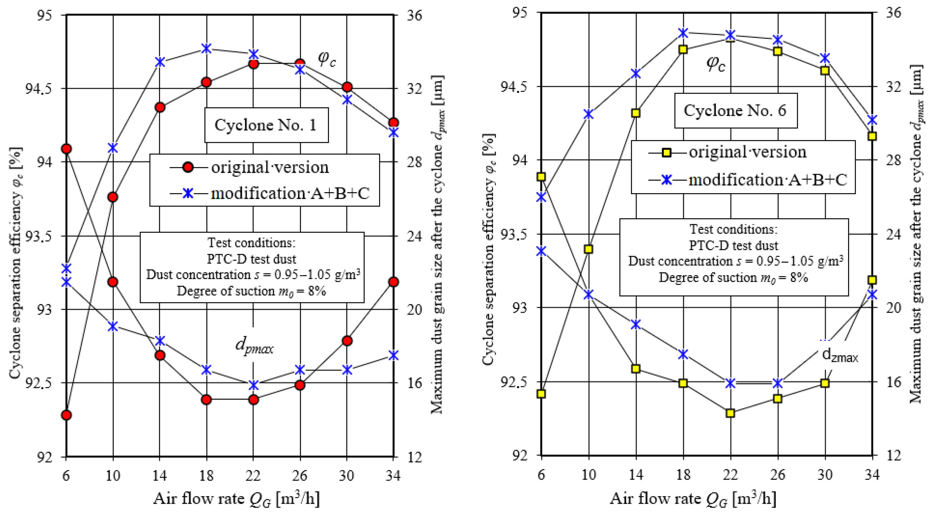
- Modification of the design of cyclones does not cause significant changes in the characteristics of separation efficiency φc and pressure drop Δpc. A visible effect of the performed modifications of the cyclones’ construction is, first of all, a significant 30% decrease in the pressure drop within the whole range of the examined flux QG, which is an effect of replacing the cylindrical cyclone outlet tube with a conical one. In addition, there is an approximately 1% increase in separation efficiency φc in the range of the smallest values of air flux QG and a shift in the maximum separation efficiency φcmax towards smaller values of air flux QG, which may result from the use of an asymmetrical inlet duct and the streamlined shape of the inlet opening of the outlet tube.
- (6)
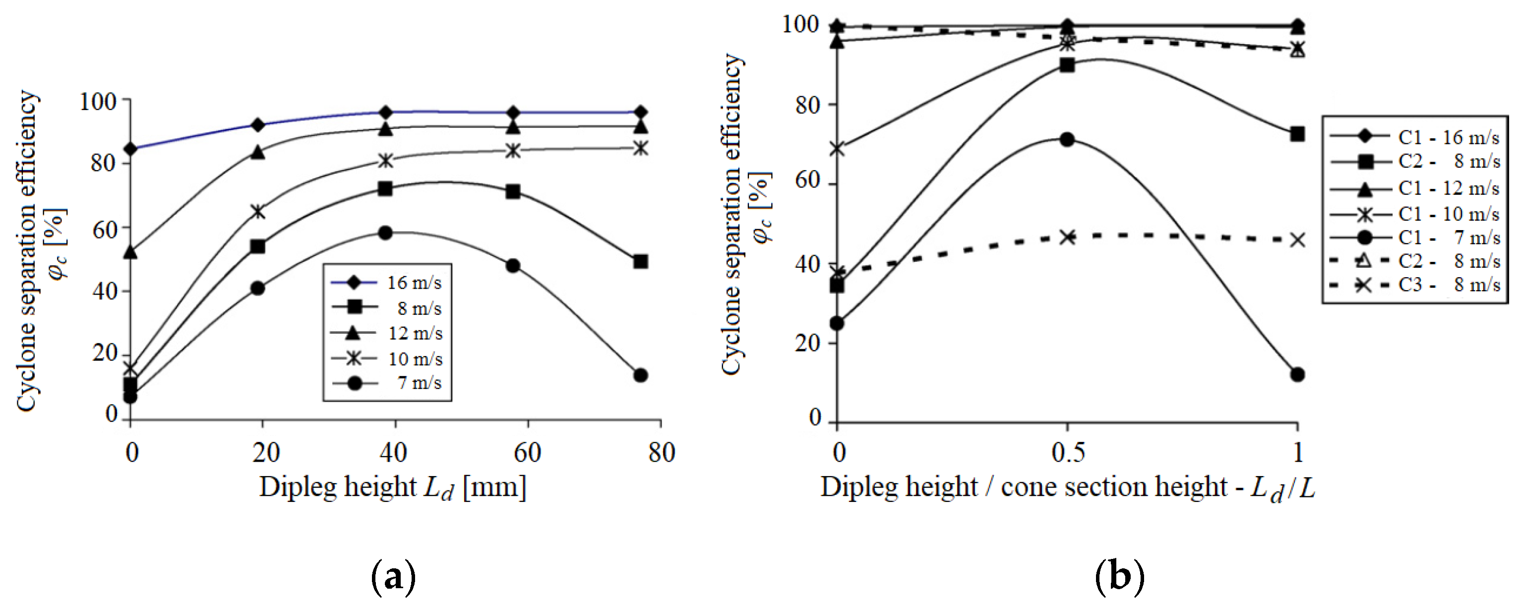
- Modification of the cyclones by elements A, B and C results in a clear decrease in the dimensions of the maximum dpmax of the dust grains for the extreme (QG = 6 m3/h i QG = 34 m3/h) values of the air stream (Figure 37) and an increase in the dimensions dpmax for the air stream in the range QG = (14–26) m3/h. At the same time, in this range, the cyclone obtains the maximum values of cyclone filtration efficiency, which indicates the range of air stream in which the operation of this cyclone should take place.
Funding
Institutional Review Board Statement
Informed Consent Statement
Data Availability Statement
Conflicts of Interest
References
- Barris, M.A. Total FiltrationTM: The Influence of Filter Selection on Engine Wear, Emissions, and Performance; SAE Technical Paper 952557; SAE: Warrendale, PA, USA, 1995. [Google Scholar]
- Schaeffer, J.W.; Olson, L.M. Air Filtration Media for Transportation Applications. Filtr. Sep. 1998, 35, 124–129. [Google Scholar]
- Jaroszczyk, T.; Pardue, B.A.; Heckel, S.P.; Kallsen, K.J. Engine air cleaner filtration performance—Theoretical and experimental background of testing. In Proceedings of the AFS Fourteenth Annual Technical Conference and Exposition, Tampa, FL, USA, 1 May 2001. Included in the Conference Proceedings (Session 16). [Google Scholar]
- Dziubak, T. Zapylenie powietrza wokół pojazdu terenowego. Wojsk. Przegląd Tech. 1990, 3, 154–157. (In Polish) [Google Scholar]
- Burda, S.; Chodnikiewicz, Z. Konstrukcja i badania pyłowe filtrów powietrza silnika czołgowego. Bull. Mil. Univ. Technol. 1962, 3, 12–34. (In Polish) [Google Scholar]
- Juda, J.; Nowicki, M. Urządzenia Odpylające; Państwowe Wydawnictwo Naukowe: Warszawa, Poland, 1986. (In Polish) [Google Scholar]
- Balicki, W.; Szczeciński, S.; Chachurski, R.; Kozakiewicz, A.; Głowacki, P.; Szczeciński, J. Problematyka filtracji powietrza wlotowego do turbinowych silników śmigłowcowych. Trans. Inst. Aviat. 2009, 199, 25–30. [Google Scholar]
- Bojdo, N.; Filippone, A. Effect of Desert Particulate Composition on Helicopter Engine Degradation Rate. In Proceedings of the 40th European Rotorcraft Forum, Southampton, UK, 2–5 September 2014. [Google Scholar] [CrossRef]
- Smialek, J.L.; Archer, F.A.; Garlick, R.G. Turbine airfoil degradation in the persian gulf war. JOM 1994, 46, 39–41. [Google Scholar] [CrossRef]
- Vogel, A.; Durant, A.J.; Cassiani, M.; Clarkson, R.J.; Slaby, M.; Diplas, S.; Krüger, K.; Stohl, A. Simulation of Volcanic Ash Ingestion Into a Large Aero Engine: Particle–Fan Interactions. ASME J. Turbomach. 2019, 141, 011010. [Google Scholar] [CrossRef] [Green Version]
- Summers, C.E. The physical characteristics of road and field dust. SAE Trans. 1925, 20, 178–197. [Google Scholar] [CrossRef]
- Pinnick, R.G.; Fernández, G.; Hinds, B.D.; Bruce, C.W.; Schaefer, R.W.; Pendleton, J.D. Dust Generated by Vehicular Traffic on Unpaved Roadways: Sizes and Infrared Extinction Characteristics. Aerosol Sci. Technol. 1985, 4, 99–121. [Google Scholar] [CrossRef]
- Long, J.; Tang, M.; Sun, Z.; Liang, Y.; Hu, J. Dust Loading Performance of a Novel Submicro-Fiber Composite Filter Medium for Engine. Materials 2018, 11, 2038. [Google Scholar] [CrossRef] [Green Version]
- Jaroszczyk, T.; Wake, J.; Fallon, S.L.; Connor, M.J. Development of Motor Vehicle Ventilation System Particulate Air Filters; SAE Technical Paper Series 962241; International Truck & Bus Meeting & Exposition: Detroit, MI, USA, 1996. [Google Scholar]
- Maddineni, A.K.; Das, D.; Damodaran, R.M. Numerical investigation of pressure and flow characteristics of pleated air filter system for automotive engine intake application. Sep. Purif. Technol. 2018, 212, 126–134. [Google Scholar] [CrossRef]
- Jaroszczyk, T.; Petrik, S.; Donahue, K. Recent Development in Heavy Duty Engine Air Filtration and the Role of Nanofiber Filter Media. J. KONES Powertrain Transp. 2009, 16, 207–216. [Google Scholar]
- Rieger, M.; Hettkamp, P.; Löhl, T.; Madeira, P.M.P. Effcient Engine Air Filter for Tight Installation Spaces. ATZ Heavy Duty Worldw. 2019, 12, 56–59. [Google Scholar] [CrossRef]
- Tian, X.; Ou, Q.; Liu, J.; Liang, Y.; Pui, D.Y. Influence of pre-stage filter selection and face velocity on the loading characteristics of a two-stage filtration system. Sep. Purif. Technol. 2019, 224, 227–236. [Google Scholar] [CrossRef]
- Muschelknautz, U. Design criteria for multicyclones in a limited space. Powder Technol. 2019, 357, 2–20. [Google Scholar] [CrossRef]
- Muschelknautz, U. Comparing Efficiency per Volume of Uniflow Cyclones and Standard Cyclones. Chem. Ing. Tech. 2020, 93, 91–107. [Google Scholar] [CrossRef]
- Otanocha, O.B.; Lin, L.; Zhou, Y.; Zhong, S.; Zhu, L. Picosecond laser surface micro-texturing for the modification of aerodynamic and dust distribution characteristics in a multi-cyclone system. Cogent Eng. 2016, 3, 1152746. [Google Scholar] [CrossRef]
- Barbolini, M.; Di Pauli, F.; Traina, M. Simulation der Luftfiltration zur Auslegung von Filterelementen. MTZ-Mot. Z. 2014, 75, 52–57. [Google Scholar] [CrossRef]
- Bojdo, N. Rotorcraft Engine Air Particle Separation. Doctoral Thesis, University of Manchester, Manchester, UK, 2012. Available online: https://www.escholar.manchester.ac.uk/uk-ac-man-scw:183545 (accessed on 2 April 2021).
- Szczepankowski, A.; Szymczak, J.; Przysowa, R. The Effect of a Dusty Environment Upon Performance and Operating Parameters of Aircraft Gas Turbine Engines. In Proceedings of the Specialists’ Meeting—Impact of Volcanic Ash Clouds on Military Operations NATO AVT-272-RSM-047, Vilnius, Lithuania, 17 May 2017. [Google Scholar]
- Worek, J.; Badura, X.; Białas, A.; Chwiej, J.; Kawoń, K.; Styszko, K. Pollution from Transport: Detection of Tyre Particles in Environmental Samples. Energies 2022, 15, 2816. [Google Scholar] [CrossRef]
- Cichowicz, R.; Dobrzański, M. Analysis of Air Pollution around a CHP Plant: Real Measurements vs. Computer Simulations. Energies 2022, 15, 553. [Google Scholar] [CrossRef]
- Ciobanu, C.; Tudor, P.; Istrate, I.-A.; Voicu, G. Assessment of Environmental Pollution in Cement Plant Areas in Romania by Co-Processing Waste in Clinker Kilns. Energies 2022, 15, 2656. [Google Scholar] [CrossRef]
- Kanageswari, S.V.; Tabil, L.G.; Sokhansanj, S. Dust and Particulate Matter Generated during Handling and Pelletization of Herbaceous Biomass: A Review. Energies 2022, 15, 2634. [Google Scholar] [CrossRef]
- Luo, H.; Zhou, W.; Jiskani, I.M.; Wang, Z. Analyzing Characteristics of Particulate Matter Pollution in Open-Pit Coal Mines: Implications for Green Mining. Energies 2021, 14, 2680. [Google Scholar] [CrossRef]
- Jaroszczyk, T.; Fallon, S.L.; Liu, Z.G.; Heckel, S.P. Development of a Method to Measure Engine Air Cleaner Fractional Effi-ciency. SAE Trans. 1999, 1089, 9–18. [Google Scholar]
- Grafe, T.; Gogins, M.; Barris, M.; Schaefer, J.; Canepa, R. Nanofibers in Filtration Applications in Transportation. In Proceedings of the Filtration 2001 International Conference and Exposition of the INDA (Association of the Nowovens Fabric Industry), Chicago, IL, USA, 3–5 December 2001; Available online: https://www.yumpu.com/en/document/read/7555561/nanofiber-in-filtration-applications-in-transportation-donaldson- (accessed on 22 May 2022).
- Schulze, M.; Taufkirch, G. Papierluftfilter Nutzfahrzeugen. MTZ Mot. Z. 1991, 1991, 52. [Google Scholar]
- Duan, J.; Gao, S.; Lu, Y.; Wang, W.; Zhang, P.; Li, C. Study and optimization of flow field in a novel cyclone separator with inner cylinder. Adv. Powder Technol. 2020, 31, 4166–4179. [Google Scholar] [CrossRef]
- Cortés, C.; Gil, A. Modeling the gas and particle flow inside cyclone separators. Prog. Energy Combust. Sci. 2007, 33, 409–452. [Google Scholar] [CrossRef]
- Zhang, W.; Zhang, L.; Yang, J.; Hao, X.; Guan, G.; Gao, Z. An experimental modeling of cyclone separator efficiency with PCA-PSO-SVR algorithm. Powder Technol. 2019, 347, 114–124. [Google Scholar] [CrossRef]
- Dziubak, T.; Bąkała, L.; Karczewski, M.; Tomaszewski, M. Numerical research on vortex tube separator for special vehicle engine inlet air filter. Sep. Purif. Technol. 2019, 237, 116463. [Google Scholar] [CrossRef]
- Wang, J.; Kim, S.C.; Pui, D.Y.H. Figure of Merit of Composite Filters with Micrometer and Nanometer Fibers. Aerosol Sci. Technol. 2008, 42, 722–728. [Google Scholar] [CrossRef]
- Dirgo, J.; Leith, D. Performance of Theoretically Optimised Cyclones. Filtr. Sep. 1985, 22, 119–125. [Google Scholar]
- Juda, J. Pomiary Zapylenia i Technika Odpylania; WNT: Warszawa, Poland, 1968. (In Polish) [Google Scholar]
- Kabsch, P. Odpylanie i Odpylacze; WNT: Warszawa, Poland, 1992. (In Polish) [Google Scholar]
- Robinson, K.S.; Hamblin, C. Ivestigating Droplet Collection in Helices and a Comparison with Conventional Demisters. Filtr. Sep. 1986, 24, 166. [Google Scholar]
- Swift, P. An Empirical Approach to Cyclone Design and Application. Filtr. Sep. 1986, 23, 24–27. [Google Scholar]
- Warych, J. Oczyszczanie Gazów-Procesy i Aparatura; WNT: Warszawa, Poland, 1998. (In Polish) [Google Scholar]
- Wheeldon, J.M.; Burnard, G.K. Performance of Cyclones in the Off-Gas Path of a Pressurised Fluidised Bed Combustor. Filtr. Sep. 1987, 24, 178–187. [Google Scholar]
- Gimbun, J.; Chuah, T.G.; Choong, T.S.Y.; Fakhru’L-Razi, A. A CFD Study on the Prediction of Cyclone Collection Efficiency. Int. J. Comput. Methods Eng. Sci. Mech. 2005, 6, 161–168. [Google Scholar] [CrossRef]
- Leith, D.; Mehta, D. Cyclone performance and design. Atmosp. Environ. 1973, 7, 527–549. [Google Scholar] [CrossRef]
- Kim, J.C.; Lee, K.W. Experimental Study of Particle Collection by Small Cyclones. Aerosol Sci. Technol. 1990, 12, 1003–1015. [Google Scholar] [CrossRef]
- Dirgo, J.; Leith, D. Cyclone Collection Efficiency: Comparison of Experimental Results with Theoretical Predictions. Aerosol Sci. Technol. 1985, 4, 401–415. [Google Scholar] [CrossRef] [Green Version]
- Ramachandran, G.; Leith, D.; Dirgo, J.; Feldman, H. Cyclone Optimization Based on a New Empirical Model for Pressure Drop. Aerosol Sci. Technol. 1991, 15, 135–148. [Google Scholar] [CrossRef]
- Iozia, D.L.; Leith, D. The Logistic Function and Cyclone Fractional Efficiency. Aerosol Sci. Technol. 1990, 12, 598–606. [Google Scholar] [CrossRef] [Green Version]
- Karagoz, I.; Avci, A. Modelling of the Pressure Drop in Tangential Inlet Cyclone Separators. Aerosol Sci. Technol. 2005, 39, 857–865. [Google Scholar] [CrossRef]
- Hsiao, T.-C.; Huang, S.-H.; Hsu, C.-W.; Chen, C.-C.; Chang, P.-K. Effects of the geometric configuration on cyclone performance. J. Aerosol Sci. 2015, 86, 1–12. [Google Scholar] [CrossRef]
- Wu, J.-P.; Zhang, Y.-H.; Wang, H.-L. Numerical study on tangential velocity indicator of free vortex in the cyclone. Sep. Purif. Technol. 2014, 132, 541–551. [Google Scholar] [CrossRef]
- Altmeyer, S.; Mathieu, V.; Jullemier, S.; Contal, P.; Midoux, N.; Rode, S.; Leclerc, J.-P. Comparison of different models of cyclone prediction performance for various operating conditions using a general software. Chem. Eng. Process. Process Intensif. 2004, 43, 511–522. [Google Scholar] [CrossRef]
- Zhao, B. Development of a Dimensionless Logistic Model for Predicting Cyclone Separation Efficiency. Aerosol Sci. Technol. 2010, 44, 1105–1112. [Google Scholar] [CrossRef] [Green Version]
- Zhou, F.; Sun, G.; Zhang, Y.; Ci, H.; Wei, Q. Experimental and CFD study on the effects of surface roughness on cyclone performance. Sep. Purif. Technol. 2018, 193, 175–183. [Google Scholar] [CrossRef]
- Hoffmann, A.C.; Arends, H.; Sie, H. An Experimental Investigation Elucidating the Nature of the Effect of Solids Loading on Cyclone Performance. Filtr. Sep. 1991, 28, 188–193. [Google Scholar] [CrossRef]
- Zhu, Y.; Lee, K. Experimental study on small cyclones operating at high flowrates. J. Aerosol Sci. 1999, 30, 1303–1315. [Google Scholar] [CrossRef]
- Elsayed, K.; Lacor, C. The effect of cyclone inlet dimensions on the flow pattern and performance. Appl. Math. Model. 2011, 35, 1952–1968. [Google Scholar] [CrossRef] [Green Version]
- Beaulac, P.; Issa, M.; Ilinca, A.; Brousseau, J. Parameters Affecting Dust Collector Efficiency for Pneumatic Conveying: A Review. Energies 2022, 15, 916. [Google Scholar] [CrossRef]
- Le, D.K.; Yoon, J.Y. Numerical investigation on the performance and flow pattern of two novel innovative designs of four-inlet cyclone separator. Chem. Eng. Process. Process Intensif. 2020, 150, 107867. [Google Scholar] [CrossRef]
- Safikhani, H.; Zamani, J.; Musa, M. Numerical study of flow field in new design cyclone separators with one, two and three tangential inlets. Adv. Powder Technol. 2018, 29, 611–622. [Google Scholar] [CrossRef]
- Mazyan, W.; Ahmadi, A.; Brinkerhoff, J.; Ahmed, H.; Hoorfar, M. Enhancement of cyclone solid particle separation performance based on geometrical modification: Numerical analysis. Sep. Purif. Technol. 2018, 191, 276–285. [Google Scholar] [CrossRef]
- Brar, L.S.; Elsayed, K. Analysis and optimization of multi-inlet gas cyclones using large eddy simulation and artificial neural network. Powder Technol. 2017, 311, 465–483. [Google Scholar] [CrossRef]
- El-Emam, M.A.; Shi, W.; Zhou, L. CFD-DEM simulation and optimization of gas-cyclone performance with realistic macroscopic particulate matter. Adv. Powder Technol. 2019, 30, 2686–2702. [Google Scholar] [CrossRef]
- Sun, Z.; Liang, L.; Liu, Q.; Yu, X. Effect of the particle injection position on the performance of a cyclonic gas solids classifier. Adv. Powder Technol. 2019, 31, 227–233. [Google Scholar] [CrossRef]
- Lim, J.-H.; Park, S.-I.; Lee, H.-J.; Zahir, M.Z.; Yook, S.-J. Performance evaluation of a tangential cyclone separator with additional inlets on the cone section. Powder Technol. 2019, 359, 118–125. [Google Scholar] [CrossRef]
- Wang, S.; Li, H.; Wang, R.; Wang, X.; Tian, R.; Sun, Q. Effect of the inlet angle on the performance of a cyclone separator using CFD-DEM. Adv. Powder Technol. 2018, 30, 227–239. [Google Scholar] [CrossRef]
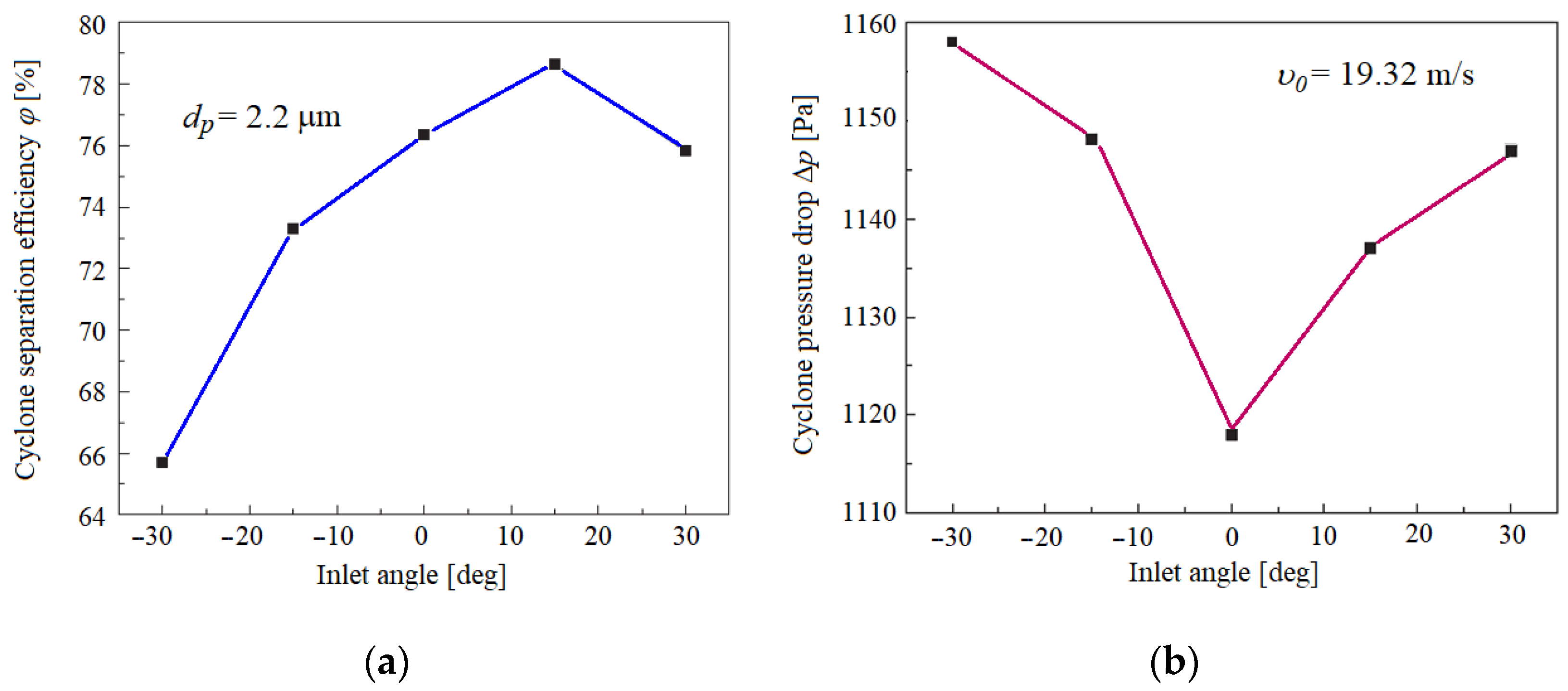
- Wasilewski, M.; Brar, L.S. Effect of the inlet duct angle on the performance of cyclone separators. Sep. Purif. Technol. 2018, 213, 19–33. [Google Scholar] [CrossRef]
- Yoshida, H.; Ono, K.; Fukui, K. The effect of a new method of fluid flow control on submicron particle classification in gas-cyclones. Powder Technol. 2005, 149, 139–147. [Google Scholar] [CrossRef]
- Mandsandulia, D.; Andersson, A.G.; Lundström, T.S. Effects of the inlet angle on the collection efficiency of a cyclone with helical-roof inlet. Powder Technol. 2017, 305, 48–55. [Google Scholar]
- Misiulia, D.; Andersson, A.G.; Lundström, T.S. Effects of the inlet angle on the flow pattern and pressure drop of a cyclone with helical-roof inlet. Chem. Eng. Res. Des. 2015, 102, 307–321. [Google Scholar] [CrossRef]
- Lim, K.; Kwon, S.-B.; Lee, K. Characteristics of the collection efficiency for a double inlet cyclone with clean air. J. Aerosol Sci. 2003, 34, 1085–1095. [Google Scholar] [CrossRef]
- Zhao, B.; Shen, H.; Kang, Y. Development of a symmetrical spiral inlet to improve cyclone separator performance. Powder Technol. 2004, 145, 47–50. [Google Scholar] [CrossRef]
- Bernardo, S.; Mori, M.; Peres, A.; Dionísio, R. 3-D computational fluid dynamics for gas and gas-particle flows in a cyclone with different inlet section angles. Powder Technol. 2006, 162, 190–200. [Google Scholar] [CrossRef]
- Chen, L.; Ma, H.; Sun, Z.; Ma, G.; Li, P.; Li, C.; Cong, X. Effect of inlet periodic velocity on the performance of standard cyclone separators. Powder Technol. 2022, 402, 117347. [Google Scholar] [CrossRef]
- Wei, Q.; Sun, G.; Gao, C. Numerical analysis of axial gas flow in cyclone separators with different vortex finder diameters and inlet dimensions. Powder Technol. 2020, 369, 321–333. [Google Scholar] [CrossRef]
- Yao, Y.; Huang, W.; Wu, Y.; Zhang, Y.; Zhang, M.; Yang, H.; Lyu, J. Effects of the inlet duct length on the flow field and performance of a cyclone separator with a contracted inlet duct. Powder Technol. 2021, 393, 12–22. [Google Scholar] [CrossRef]
- Dzierżanowski, P.; Kordziński, W.; Otyś, J.; Szczeciński, S.; Wiatrek, R. Napędy lotnicze. In Turbinowe Silniki Śmigłowe i Śmigłowcowe; WKŁ: Warszawa, Poland, 1985. (In Polish) [Google Scholar]
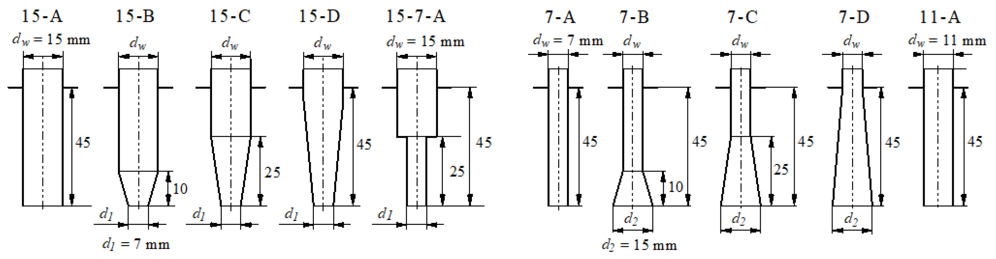
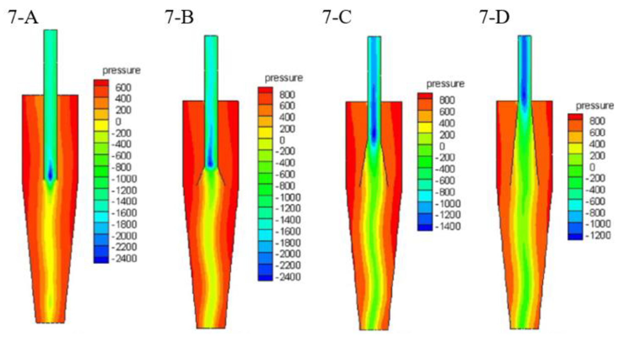
- Lim, K.; Kim, H.; Lee, K. Characteristics of the collection efficiency for a cyclone with different vortex finder shapes. J. Aerosol Sci. 2004, 35, 743–754. [Google Scholar] [CrossRef]
- Raoufi, A.; Shams, M.; Farzaneh, M.; Ebrahimi, R. Numerical simulation and optimization of fluid flow in cyclone vortex finder. Chem. Eng. Process. Process Intensif. 2008, 47, 128–137. [Google Scholar] [CrossRef]
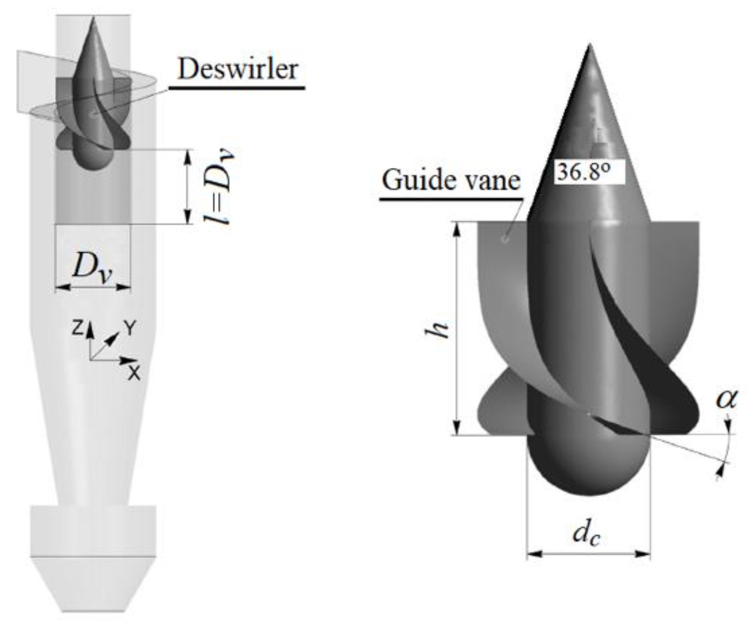
- Misiulia, D.; Elsayed, K.; Andersson, A.G. Geometry optimization of a deswirler for cyclone separator in terms of pressure drop using CFD and artificial neural network. Sep. Purif. Technol. 2017, 185, 10–23. [Google Scholar] [CrossRef]
- Misyulya, D.I. New Designs of Devices for a Decrease in Power Consumption of Cyclone Dust Collectors. Russ. J. Non Ferr. Met. 2012, 53, 67–72. [Google Scholar] [CrossRef]
- Qiang, L.; Qinggong, W.; Weiwei, X.; Zilin, Z.; Konghao, Z. Experimental and computational analysis of a cyclone separator with a novel vortex finder. Powder Technol. 2019, 360, 398–410. [Google Scholar] [CrossRef]
- Wang, Z.; Sun, G.; Jiao, Y. Experimental study of large-scale single and double inlet cyclone separators with two types of vortex finder. Chem. Eng. Process. Process Intensif. 2020, 158, 108188. [Google Scholar] [CrossRef]
- Yohana, E.; Tauviqirrahman, M.; Laksono, D.A.; Charles, H.; Choi, K.-H.; Yulianto, M.E. Innovation of vortex finder geometry (tapered in-cylinder out) and additional cooling of body cyclone on velocity flow field, performance, and heat transfer of cyclone separator. Powder Technol. 2022, 399, 117235. [Google Scholar] [CrossRef]
- Elsayed, K.; Parvaz, F.; Hosseini, S.H.; Ahmadi, G. Influence of the dipleg and dustbin dimensions on performance of gas cyclones: An optimization study. Sep. Purif. Technol. 2020, 239, 116553. [Google Scholar] [CrossRef]
- Parvaz, F.; Hosseini, S.H.; Elsayed, K.; Ahmadi, G. Influence of the dipleg shape on the performance of gas cyclones. Sep. Purif. Technol. 2019, 233, 116000. [Google Scholar] [CrossRef]
- Kaya, F.; Karagoz, I. Numerical investigation of performance characteristics of a cyclone prolonged with a dipleg. Chem. Eng. J. 2009, 151, 39–45. [Google Scholar] [CrossRef]
- Qian, F.; Zhang, J.; Zhang, M. Effects of the prolonged vertical tube on the separation performance of a cyclone. J. Hazard. Mater. 2006, 136, 822–829. [Google Scholar] [CrossRef]
- Wasilewski, M. Analysis of the effect of counter-cone location on cyclone separator efficiency. Sep. Purif. Technol. 2017, 179, 236–247. [Google Scholar] [CrossRef]
- Yoshida, H. Effect of apex cone shape and local fluid flow control method on fine particle classification of gas-cyclone. Chem. Eng. Sci. 2012, 85, 55–61. [Google Scholar] [CrossRef]
- Yoshida, H.; Nishimura, Y.; Fukui, K.; Yamamoto, T. Effect of apex cone shape on fine particle classification of gas-cyclone. Powder Technol. 2010, 204, 54–62. [Google Scholar] [CrossRef] [Green Version]
- Yoshida, H.; Kwan-Sik, Y.; Fukui, K.; Akiyama, S.; Taniguchi, S. Effect of apex cone height on particle classification per-formance of a cyclone separator. Adv. Powder Technol. 2003, 14, 263–266. [Google Scholar] [CrossRef]
- Kępa, A. The efficiency improvement of a large-diameter cyclone—The CFD calculations. Sep. Purif. Technol. 2013, 118, 105–111. [Google Scholar] [CrossRef]
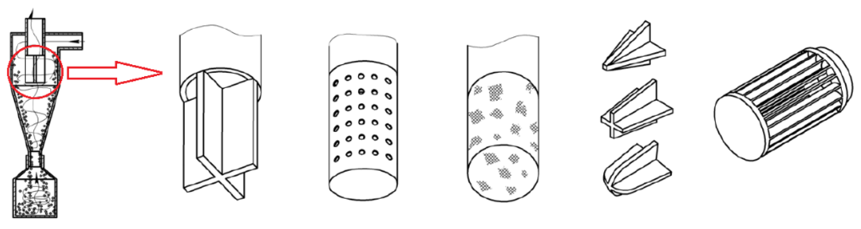
- Obermair, S.; Woisetschläger, J.; Staudinger, G. Investigation of the flow pattern in different dust outlet geometries of a gas cyclone by laser Doppler anemometry. Powder Technol. 2003, 138, 239–251. [Google Scholar] [CrossRef]
- Dziubak, T. Experimental Studies of Dust Suction Irregularity from Multi-Cyclone Dust Collector of Two-Stage Air Filter. Energies 2021, 14, 3577. [Google Scholar] [CrossRef]
- Bukowski, J. Mechanika Płynów; PWN: Warszawa, Poland, 1968. (In Polish) [Google Scholar]
- PN-ISO 5011; Filtry Powietrza do Silników Spalinowych i Sprężarek. PKNM: Warszawa, Poland, 1994. (In Polish)
- Ma, L.; Ingham, D.; Wen, X. Numerical modelling of the fluid and particle penetration through small sampling cyclones. J. Aerosol Sci. 2000, 31, 1097–1119. [Google Scholar] [CrossRef]


| QG (m3/h) | υ0 (m/s) | dzgr (μm) | ||
|---|---|---|---|---|
| SiO2 ρzp = 2.65 g/cm3 | Al2O3 ρzp = 3.99 (g/cm3) | Fe2O3 ρzp = 5.24 (g/cm3) | ||
| 6 | 5.65 | 2.23 | 1.85 | 1.59 |
| 22 | 20.6 | 1.16 | 0.96 | 0.84 |
| 34 | 31.8 | 0.94 | 0.79 | 0.68 |
Publisher’s Note: MDPI stays neutral with regard to jurisdictional claims in published maps and institutional affiliations. |
© 2022 by the author. Licensee MDPI, Basel, Switzerland. This article is an open access article distributed under the terms and conditions of the Creative Commons Attribution (CC BY) license (https://creativecommons.org/licenses/by/4.0/).
Share and Cite
Dziubak, T. Experimental Investigation of Possibilities to Improve Filtration Efficiency of Tangential Inlet Return Cyclones by Modification of Their Design. Energies 2022, 15, 3871. https://doi.org/10.3390/en15113871
Dziubak T. Experimental Investigation of Possibilities to Improve Filtration Efficiency of Tangential Inlet Return Cyclones by Modification of Their Design. Energies. 2022; 15(11):3871. https://doi.org/10.3390/en15113871
Chicago/Turabian StyleDziubak, Tadeusz. 2022. "Experimental Investigation of Possibilities to Improve Filtration Efficiency of Tangential Inlet Return Cyclones by Modification of Their Design" Energies 15, no. 11: 3871. https://doi.org/10.3390/en15113871
APA StyleDziubak, T. (2022). Experimental Investigation of Possibilities to Improve Filtration Efficiency of Tangential Inlet Return Cyclones by Modification of Their Design. Energies, 15(11), 3871. https://doi.org/10.3390/en15113871