Figure 1.
Torque varies with the current angle: (a) torque component; (b) reluctance torque ratio.
Figure 1.
Torque varies with the current angle: (a) torque component; (b) reluctance torque ratio.
Figure 2.
Selected Seven Different Slot/Pole Combinations: (a) 10s6p. (b) 10s8p. (c) 20s6p. (d) 20s8p. (e) 20s12p. (f) 30s6p. (g) 40s8p.
Figure 2.
Selected Seven Different Slot/Pole Combinations: (a) 10s6p. (b) 10s8p. (c) 20s6p. (d) 20s8p. (e) 20s12p. (f) 30s6p. (g) 40s8p.
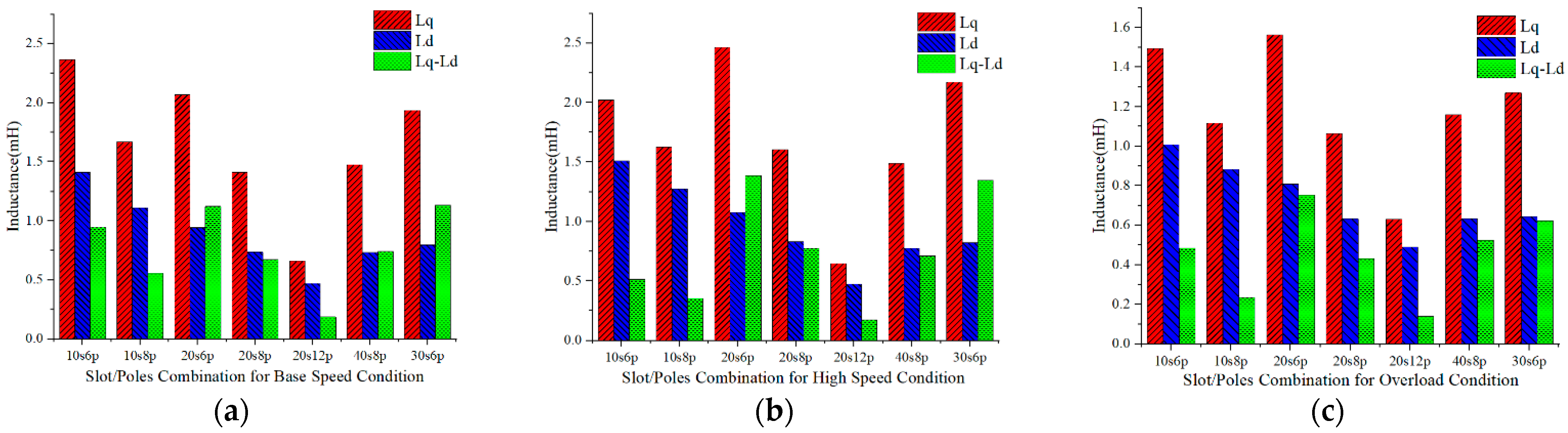
Figure 3.
Inductance characteristics in different slot/pole combinations: (a) base speed condition, (b) high-speed condition, and (c) overload speed condition.
Figure 3.
Inductance characteristics in different slot/pole combinations: (a) base speed condition, (b) high-speed condition, and (c) overload speed condition.
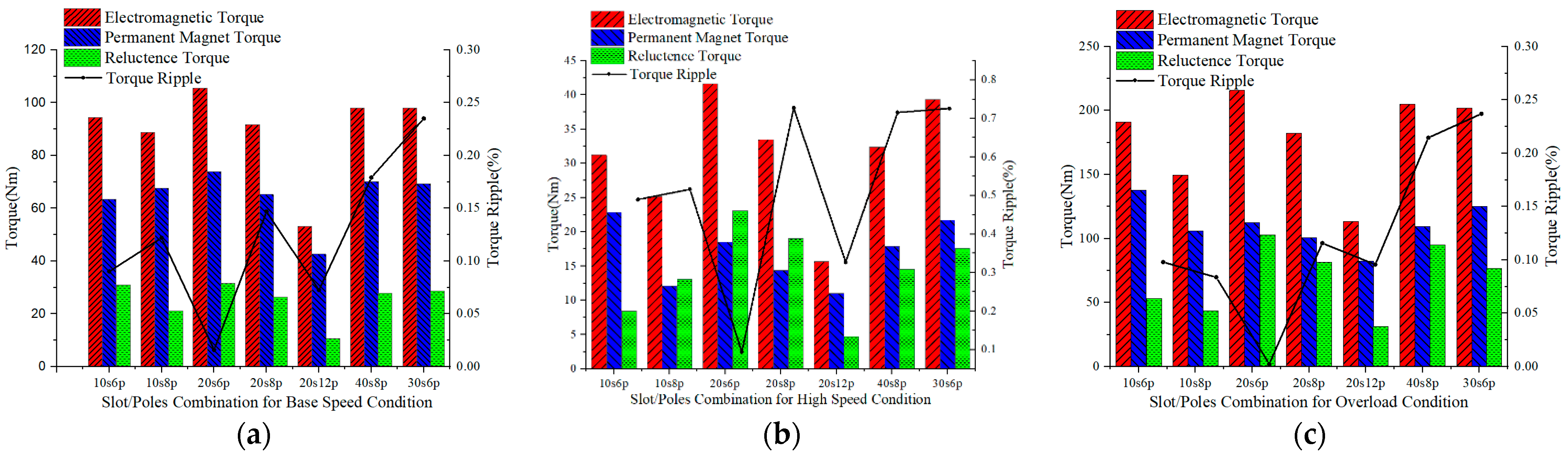
Figure 4.
Torque characteristics in different slot/pole combinations: (a) base speed condition, (b) high-speed condition, and (c) overload speed condition.
Figure 4.
Torque characteristics in different slot/pole combinations: (a) base speed condition, (b) high-speed condition, and (c) overload speed condition.
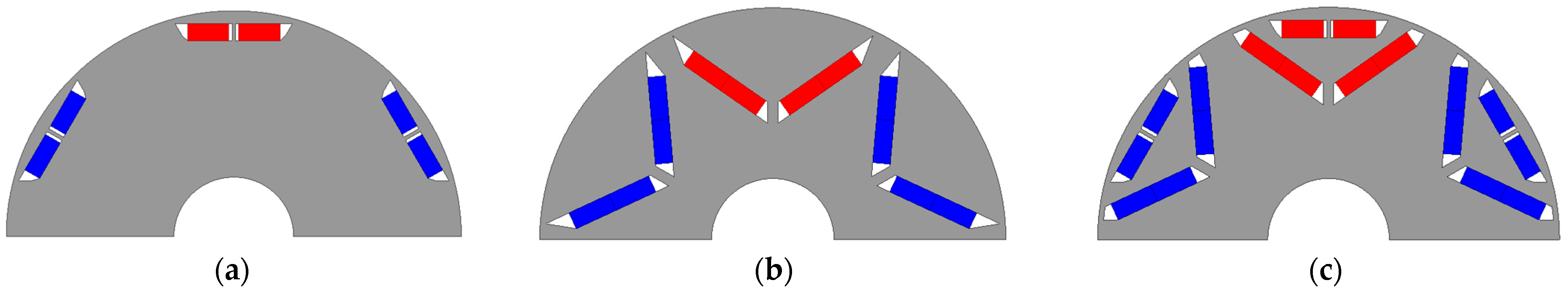
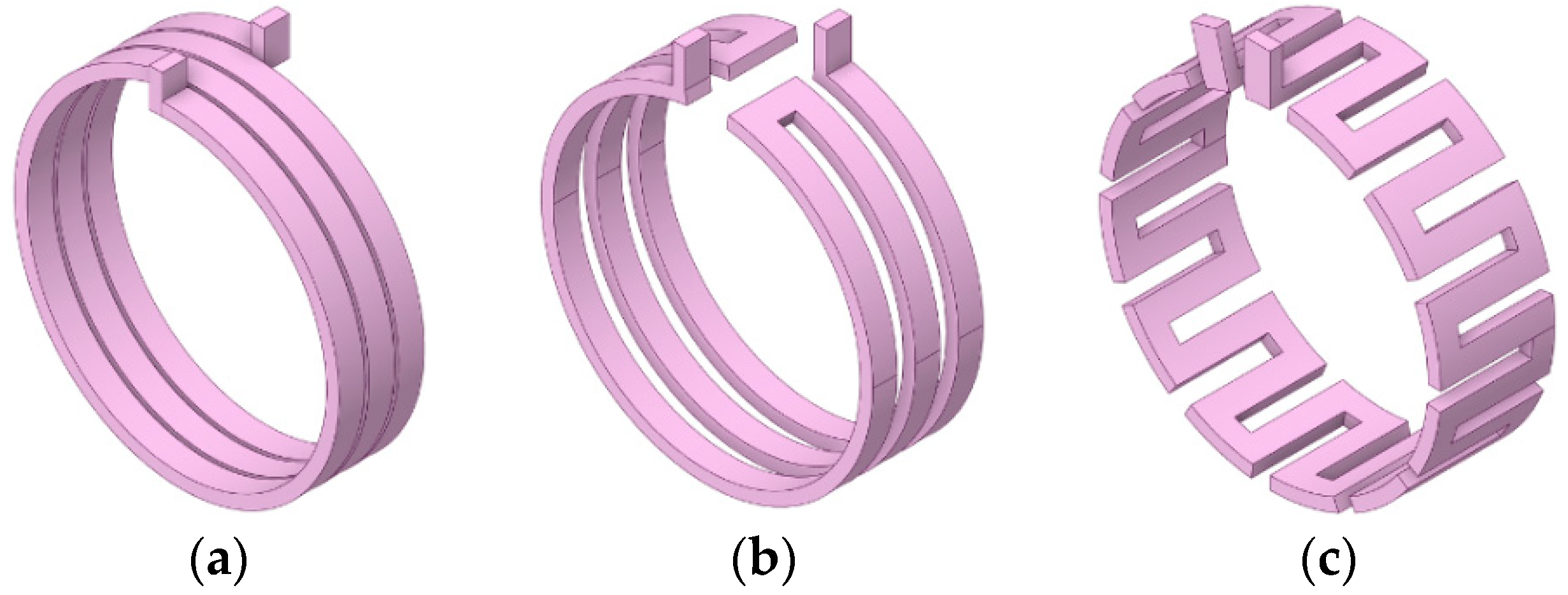
Figure 5.
IPMSM Rotor Structures: (a) Bar Shape. (b) V Shape. (c) ∇ Shape.
Figure 5.
IPMSM Rotor Structures: (a) Bar Shape. (b) V Shape. (c) ∇ Shape.
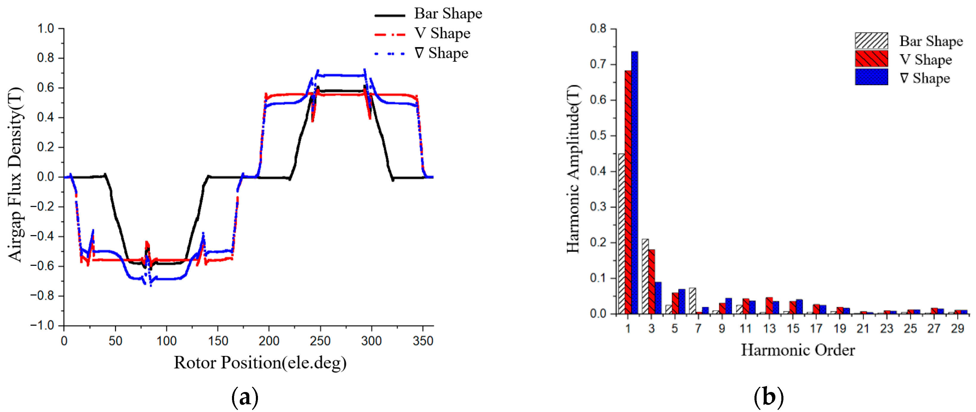
Figure 6.
IPMSM rotor structures air gap flux density performance: (a) air gap flux density waveform, (b) harmonic content.
Figure 6.
IPMSM rotor structures air gap flux density performance: (a) air gap flux density waveform, (b) harmonic content.
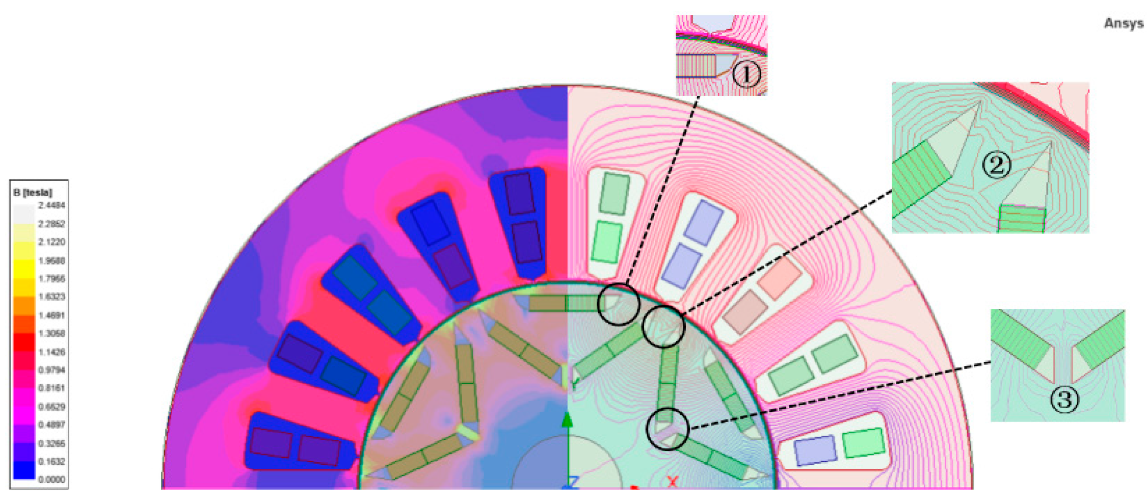
Figure 7.
No-load magnetic field distribution cloud map in ∇ shape rotor structure.
Figure 7.
No-load magnetic field distribution cloud map in ∇ shape rotor structure.
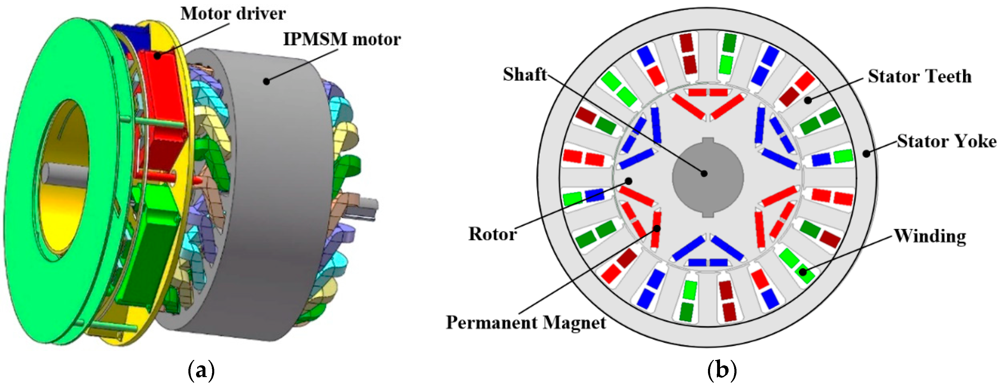
Figure 8.
Ver2.0 type topology: (a) IMDS overall structure, (b) Ver2.0 IPMSM motor structure.
Figure 8.
Ver2.0 type topology: (a) IMDS overall structure, (b) Ver2.0 IPMSM motor structure.
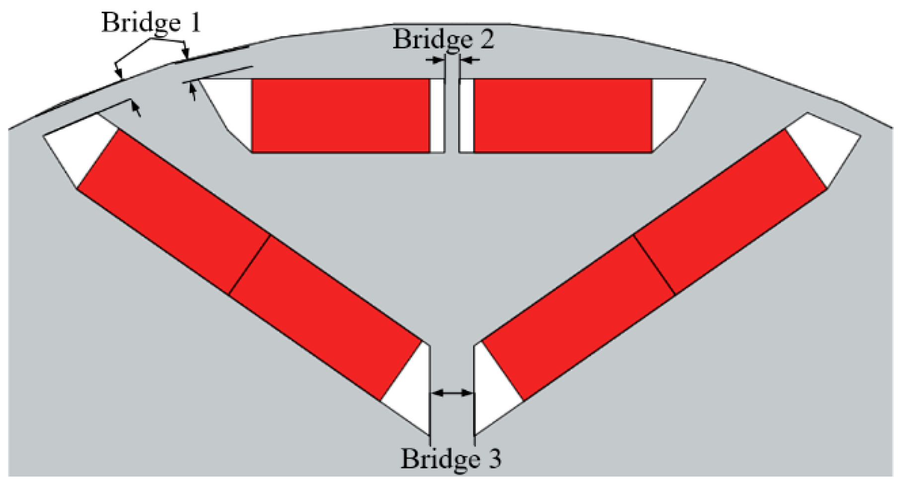
Figure 9.
Rotor magnetic bridge schematic diagram.
Figure 9.
Rotor magnetic bridge schematic diagram.
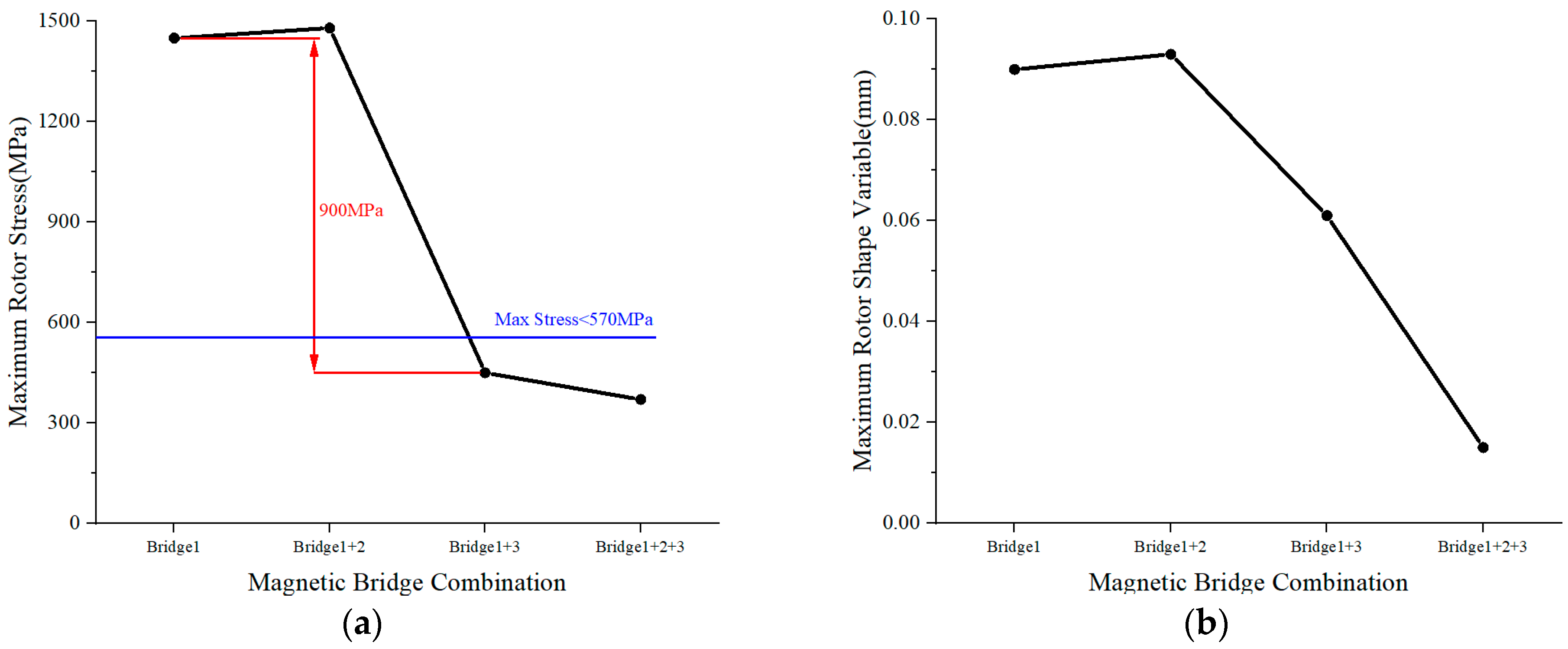
Figure 10.
Rotor stress with different magnetic bridge combinations at maximum speed conditions: (a) rotor maximum von Mises stress, (b) rotor maximum deformation quantity.
Figure 10.
Rotor stress with different magnetic bridge combinations at maximum speed conditions: (a) rotor maximum von Mises stress, (b) rotor maximum deformation quantity.
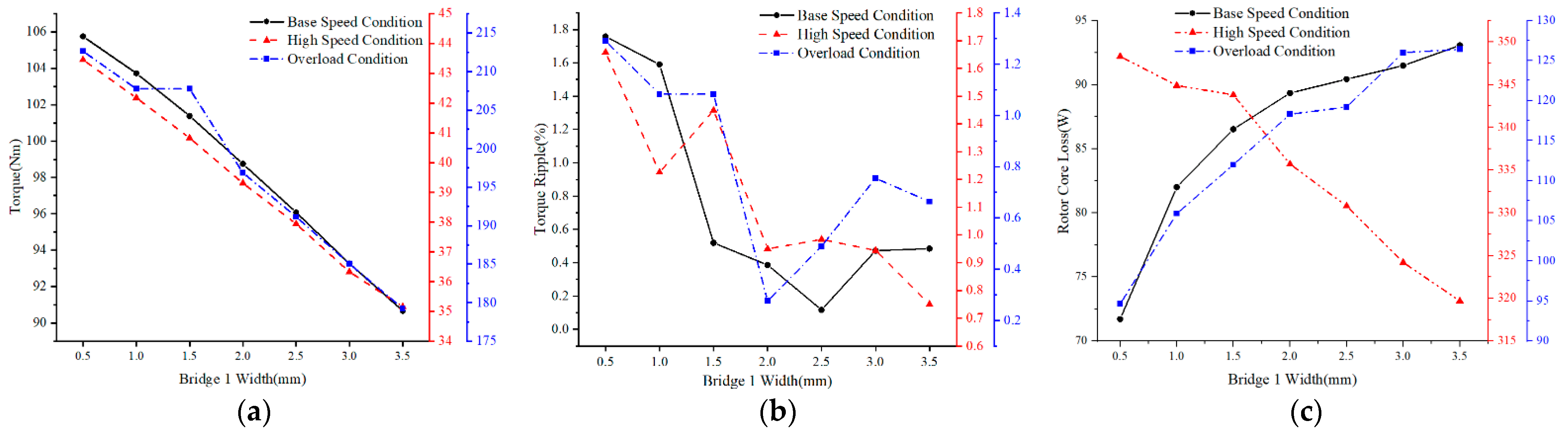
Figure 11.
Motor electromagnetic characteristics with different bridge 1 width: (a) output torque, (b) torque ripple; (c) rotor core loss.
Figure 11.
Motor electromagnetic characteristics with different bridge 1 width: (a) output torque, (b) torque ripple; (c) rotor core loss.
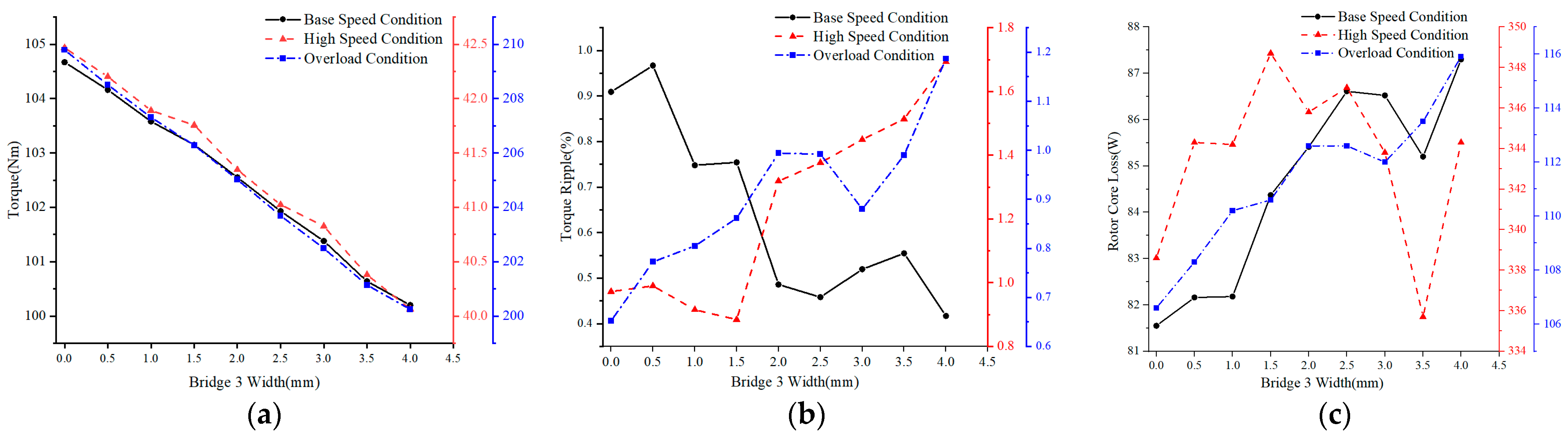
Figure 12.
Motor electromagnetic characteristics with different bridge 3 width: (a) output torque, (b) torque ripple, (c) rotor core loss.
Figure 12.
Motor electromagnetic characteristics with different bridge 3 width: (a) output torque, (b) torque ripple, (c) rotor core loss.
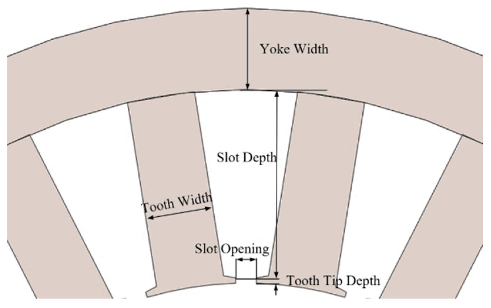
Figure 13.
Stator structure schematic diagram.
Figure 13.
Stator structure schematic diagram.
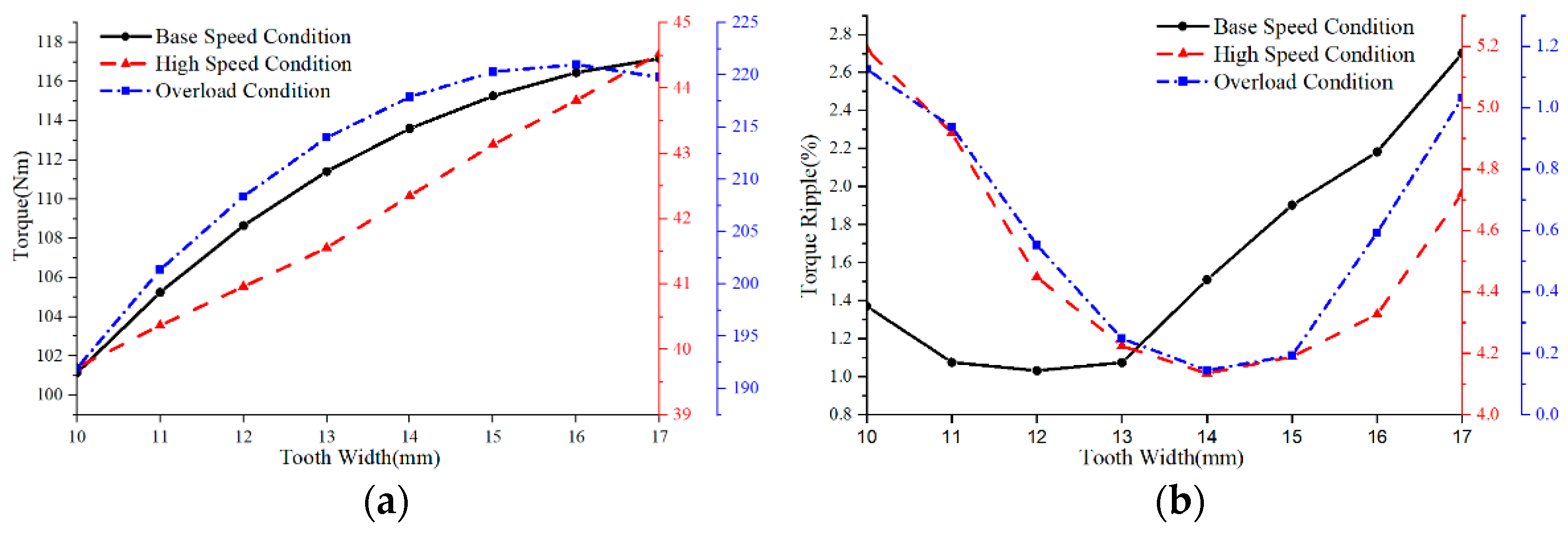
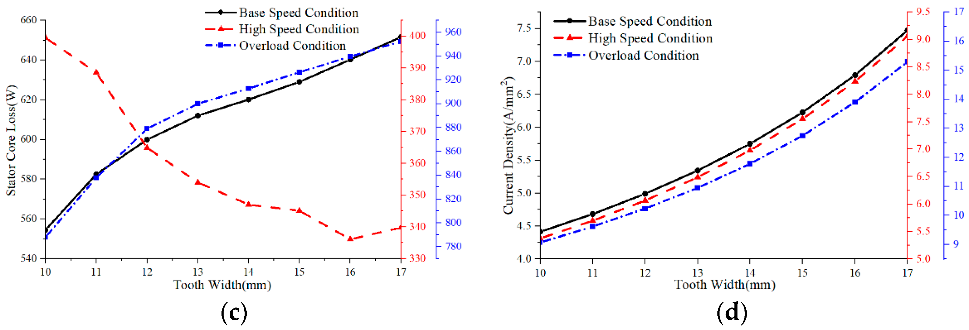
Figure 14.
Electromagnetic characteristics vary with different tooth width: (a) output torque, (b) torque ripple, (c) stator core loss, (d) current density.
Figure 14.
Electromagnetic characteristics vary with different tooth width: (a) output torque, (b) torque ripple, (c) stator core loss, (d) current density.
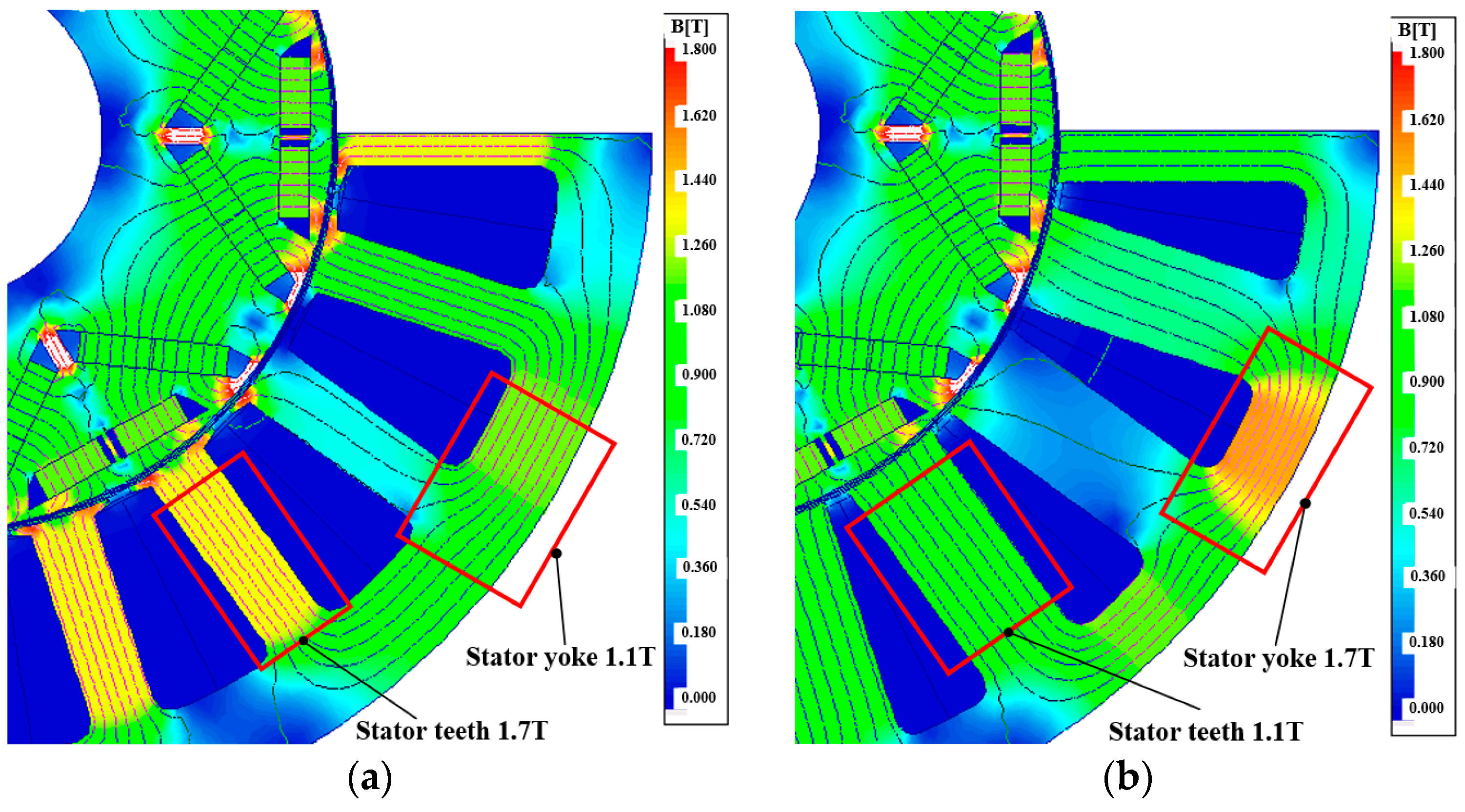
Figure 15.
Stator flux density distribution in different stator tooth widths: (a) tooth width of 11 mm, and (b) tooth width of 20 mm.
Figure 15.
Stator flux density distribution in different stator tooth widths: (a) tooth width of 11 mm, and (b) tooth width of 20 mm.
Figure 16.
Stator core loss under different tooth widths: (a) stator yoke core loss, (b) stator teeth core loss per weight.
Figure 16.
Stator core loss under different tooth widths: (a) stator yoke core loss, (b) stator teeth core loss per weight.
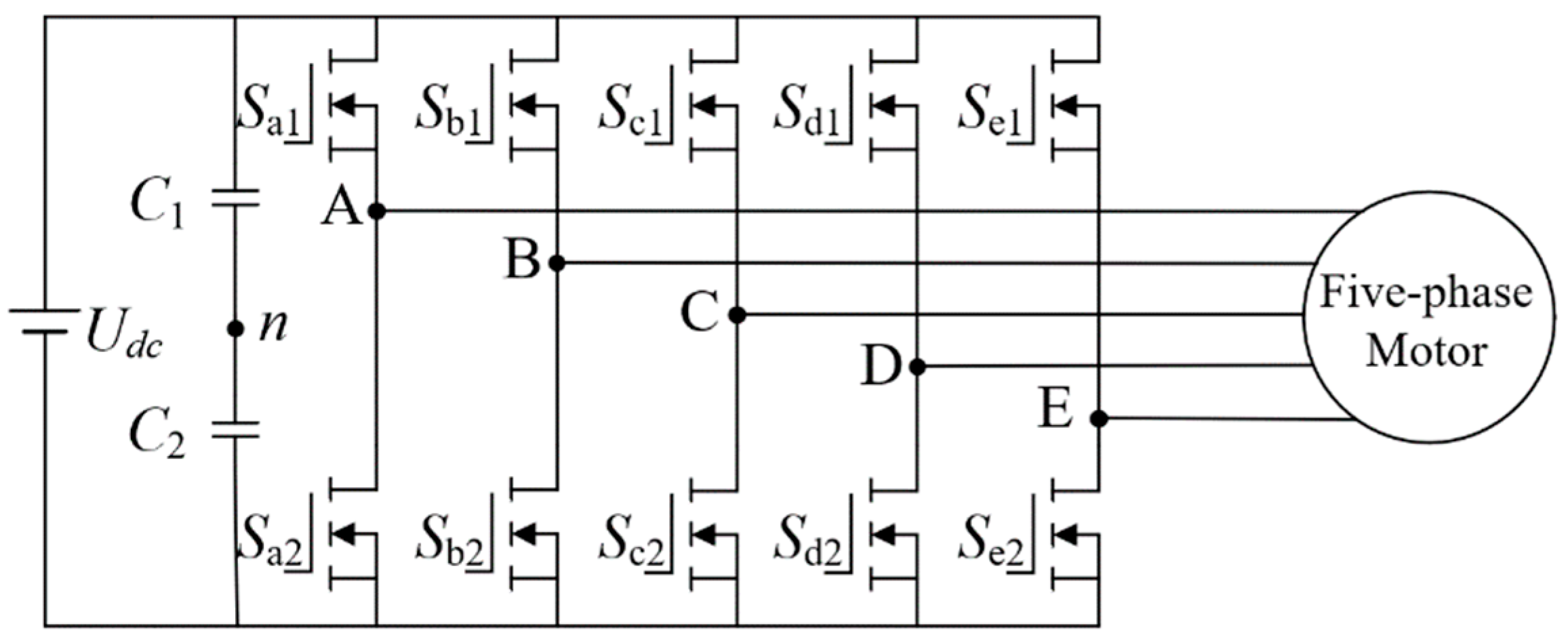
Figure 17.
The topology of the five-phase half-bridge inverter.
Figure 17.
The topology of the five-phase half-bridge inverter.
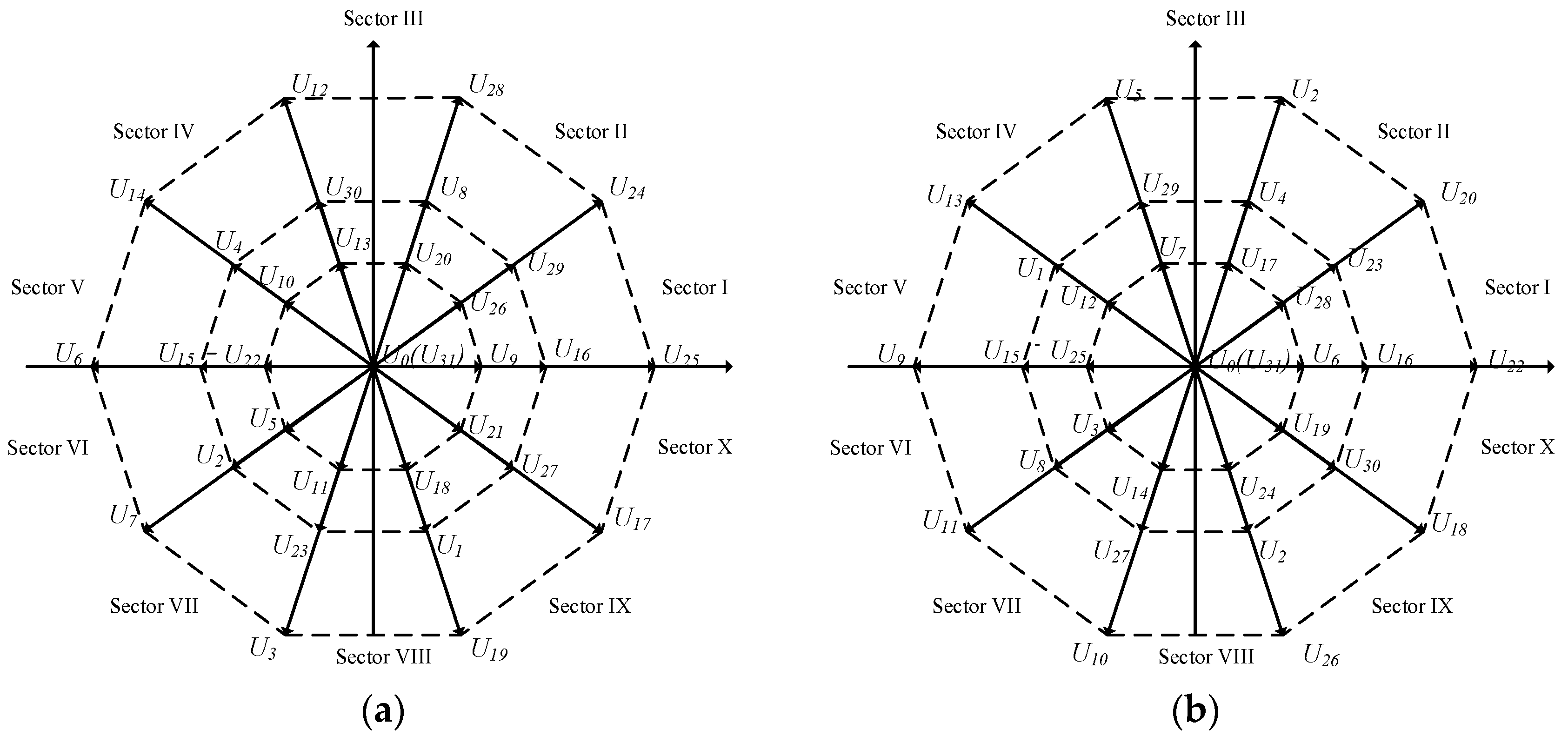
Figure 18.
Space voltage vector distribution in the fundamental and third harmonic coordinate system. (a) Fundamental α1–β1 coordinate system vector distribution. (b) third harmonic α3–β3 coordinate system vector distribution.
Figure 18.
Space voltage vector distribution in the fundamental and third harmonic coordinate system. (a) Fundamental α1–β1 coordinate system vector distribution. (b) third harmonic α3–β3 coordinate system vector distribution.
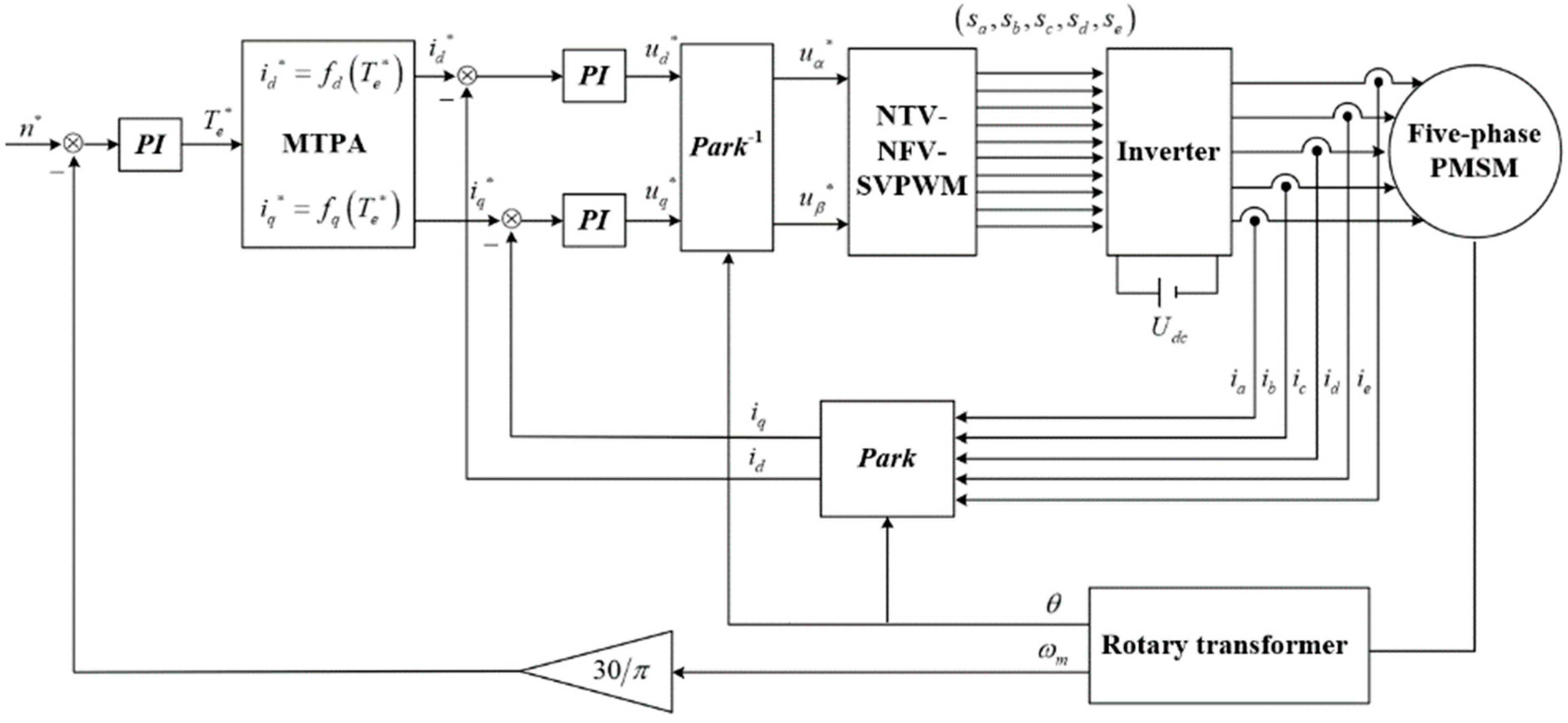
Figure 19.
MPTA control of the five-phase PMSM block diagram.
Figure 19.
MPTA control of the five-phase PMSM block diagram.
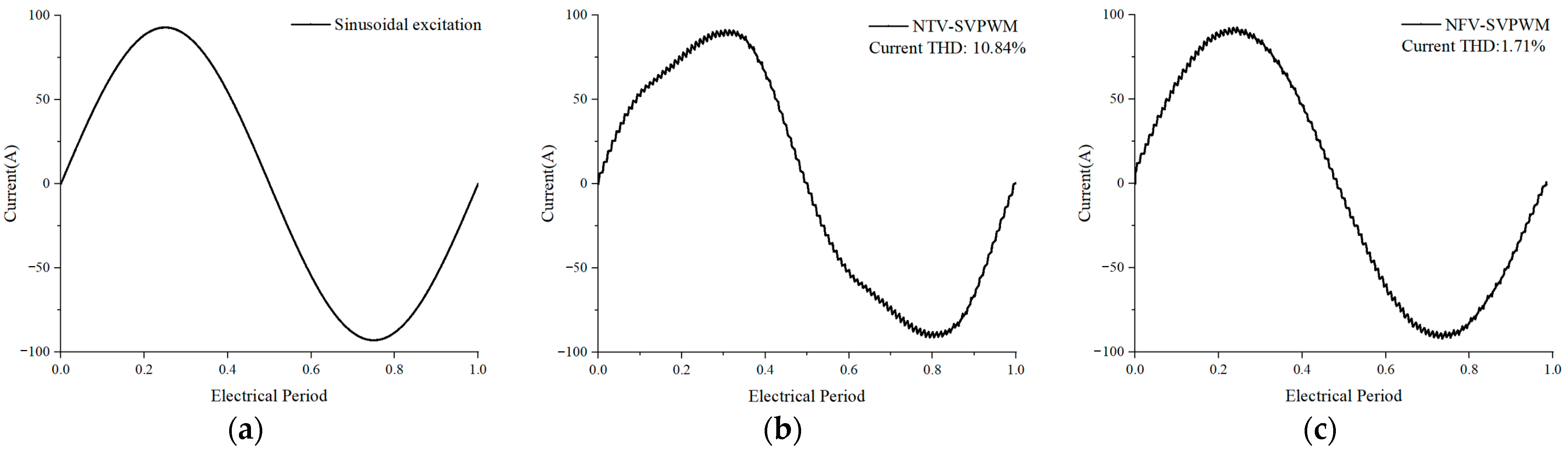
Figure 20.
Current excitation under different modulation algorithm: (a) ideal sinusoidal, (b) NTV-SVPWM, and (c) NFV-SVPWM.
Figure 20.
Current excitation under different modulation algorithm: (a) ideal sinusoidal, (b) NTV-SVPWM, and (c) NFV-SVPWM.
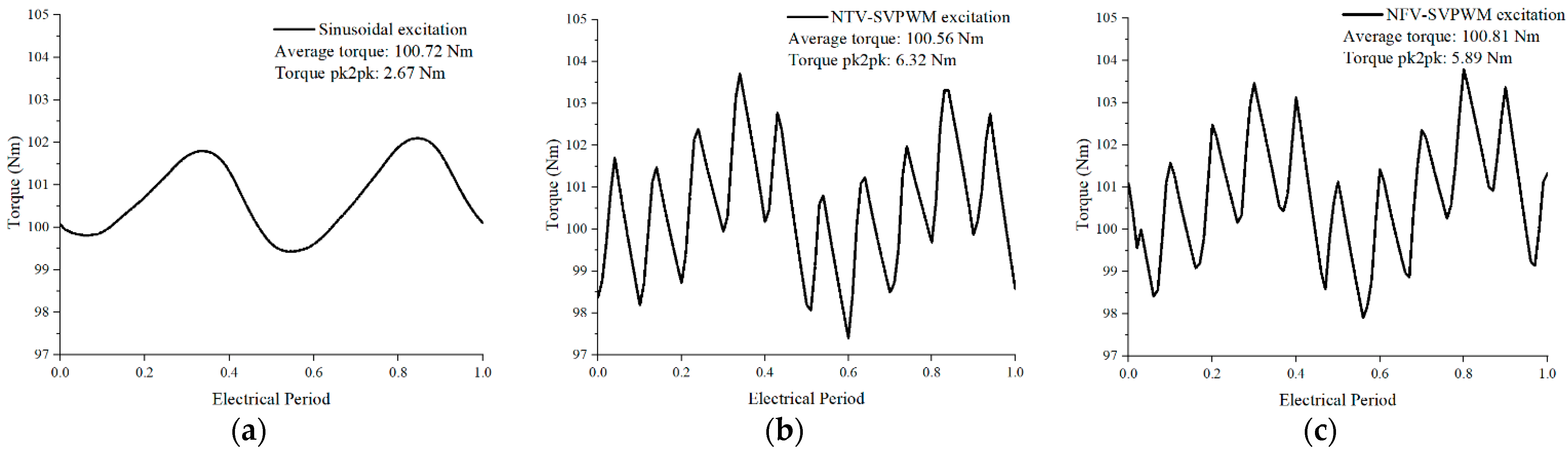
Figure 21.
Motor torque under different modulation algorithms (a) ideal sinusoidal, (b) NTV-SVPWM, and (c) NFV-SVPWM.
Figure 21.
Motor torque under different modulation algorithms (a) ideal sinusoidal, (b) NTV-SVPWM, and (c) NFV-SVPWM.
Figure 22.
Motor in IMDS topology: (a) Ver1.0 motor topology, (b) Ver2.0 motor topology.
Figure 22.
Motor in IMDS topology: (a) Ver1.0 motor topology, (b) Ver2.0 motor topology.
Figure 23.
A 60 kW high power density machine temperature field solution model.
Figure 23.
A 60 kW high power density machine temperature field solution model.
Figure 24.
Different cooling water jacket structures (a) spiral, (b) dial, and (c) axial.
Figure 24.
Different cooling water jacket structures (a) spiral, (b) dial, and (c) axial.
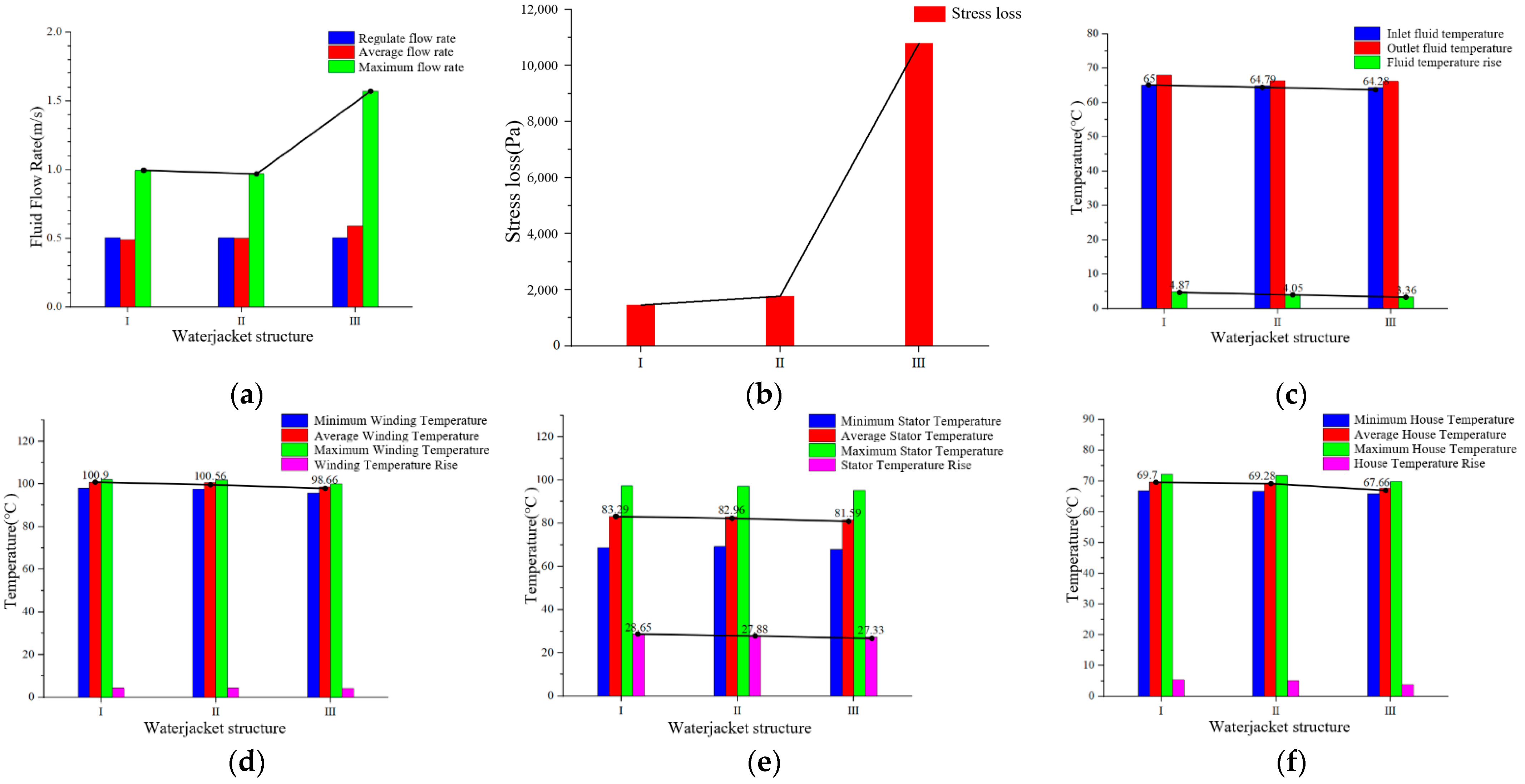
Figure 25.
Comparison of three water jacket structures: (a) fluid flow rate, (b) stress loss, (c) fluid temperature, (d) winding temperature, (e) stator temperature, and (f) water jacket temperature.
Figure 25.
Comparison of three water jacket structures: (a) fluid flow rate, (b) stress loss, (c) fluid temperature, (d) winding temperature, (e) stator temperature, and (f) water jacket temperature.
Figure 26.
Temperature field solution results under three main operation conditions: (a) base speed conditions, (b) high-speed conditions, and (c) overload conditions.
Figure 26.
Temperature field solution results under three main operation conditions: (a) base speed conditions, (b) high-speed conditions, and (c) overload conditions.
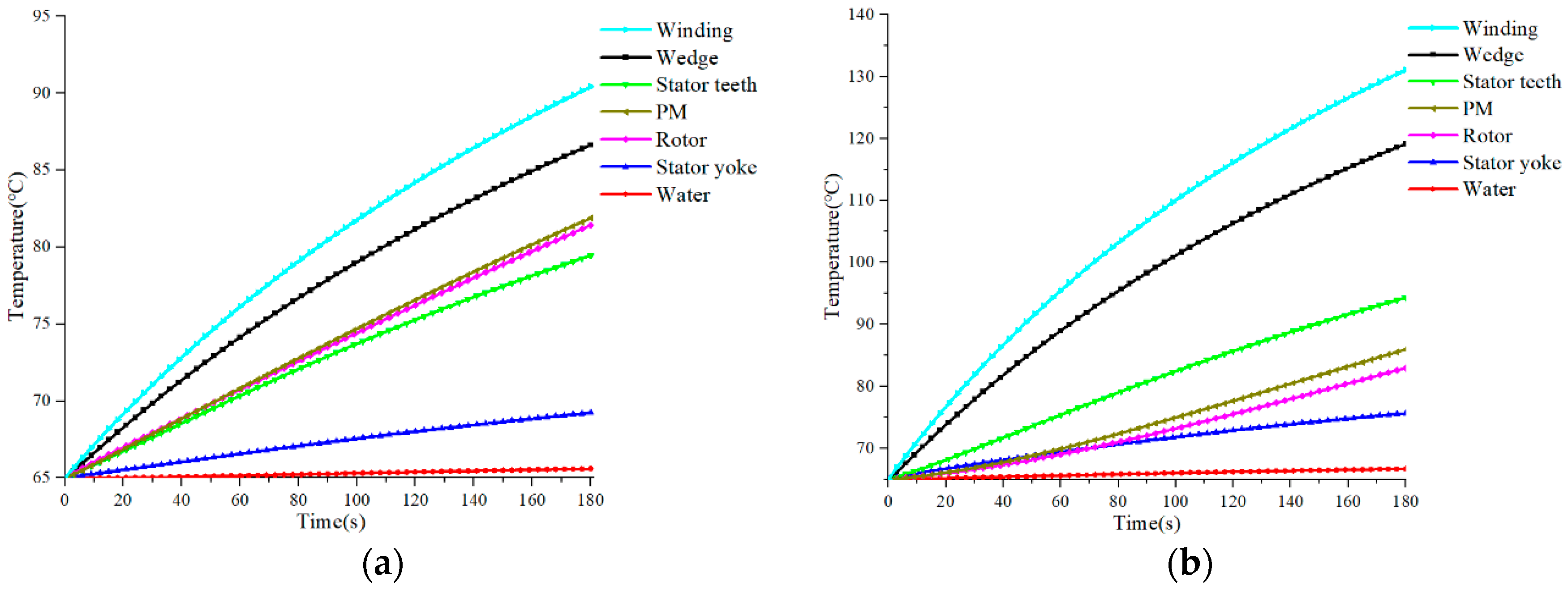
Figure 27.
Temperature change curve under transient operating conditions: (a) high-speed conditions, (b) overload Conditions.
Figure 27.
Temperature change curve under transient operating conditions: (a) high-speed conditions, (b) overload Conditions.
Table 1.
Winding coefficient under different slot/pole combination.
Table 1.
Winding coefficient under different slot/pole combination.
| Slot/Pole | 6 | 8 | 12 |
|---|
| 10 | 0.951 (y = 2) | 0.951 (y = 1) | 0.951 (y = 1) |
| 20 | 0.975 (y = 3) | 0.951 (y = 2) | 0.951 (y = 2) |
| 30 | 1.000 (y = 5) | 0.980 (y = 4) | 0.951 (y = 3) |
| 40 | 0.982 (y = 7) | 1.000 (y = 1) | 0.975 (y = 3) |
Table 2.
Motor three main operating conditions.
Table 2.
Motor three main operating conditions.
| Parameter | Base Speed | High Speed | Overload |
|---|
| Power | 60 kW | 60 kW | 110 kW |
| Speed | 6000 rpm | 15,000 rpm | 5000 rpm |
| Torque | >95.5 Nm | >38.2 Nm | >200 Nm |
| Operating time | 60 min | 3 min | 3 min |
Table 3.
Main indicators of HPDM.
Table 3.
Main indicators of HPDM.
| Parameter | Value |
|---|
| Rate power | 60 kW |
| Peak power | 110 kW |
| Base speed | 6000 rpm |
| Maximum speed | 15,000 rpm |
| Peak Torque | >200 Nm |
| Torque Ripple | <5% |
| Current density | <12 A/mm2 |
| DC bus voltage | 650 V |
| Peak current | <200 A |
| Stator outer diameter | ≤240 mm |
| Volume power density | >10 kW/L |
| Mass power density | >3 kW/kg |
Table 4.
Motor loss under different modulation algorithms.
Table 4.
Motor loss under different modulation algorithms.
| Loss | Ideal Sinusoid | NTV-SVPWM | NFV-SVPWM |
|---|
| Stator core loss | 492.36 W | 1320.9 W | 1230.4 W |
| Rotor core loss | 29.24 W | 66.8 W | 62 W |
| Magnet loss | 12.58 W | 40.25 W | 33.67 W |
| Copper loss | 332.45 W | 321.1 W | 317.84 W |
Table 5.
Motor loss under different switching frequencies using NFV-SVPWM.
Table 5.
Motor loss under different switching frequencies using NFV-SVPWM.
| Switching Frequency | Current THD | Stator Core Loss | Rotor Core Loss | Magnet Loss |
|---|
| Ideal sinusoid | 0 | 492.4 W | 29.2 W | 12.6 W |
| 3 kHz | 8.06% | 754.5 W | 80.5 W | 201.9 W |
| 9 kHz | 2.88% | 675.5 W | 68.5 W | 75.9 W |
| 15 kHz | 1.71% | 615.4 W | 62 W | 33.7 W |
| 30 kHz | 1.54% | 568.2 W | 46.8 W | 23.5 W |
| 45 kHz | 1.37% | 522.9 W | 31.6 W | 13.2 W |
Table 6.
Ver2.0 motor’s space dimensions.
Table 6.
Ver2.0 motor’s space dimensions.
| Component | Material | Mass | Volume |
|---|
| Stator | 10JNEX900 | 14.01 kg | 1.87 L |
| Rotor | 10JNEX900 | 6.17 kg | 0.83 L |
| Winding | Copper | 10.14 kg | 1.14 L |
| Magnet | N38UH | 1.49 kg | 0.19 L |
| Shaft | 20CrMnTi | 2.88 kg | 0.39 L |
| Overall | - | 35.2 kg | 4.42 L |
Table 7.
Ver2.0 motor’s main size and structure.
Table 7.
Ver2.0 motor’s main size and structure.
| Parameters | Ver1.0 | Ver2.0 |
|---|
| Stator outer diameter | 260 mm | 240 mm |
| Rotor inner diameter | 145 mm | 133 mm |
| Air gap length | 1 mm | 1 mm |
| Stator teeth width | 14 mm | 13 mm |
| Magnet segment | 3 | 9 |
| Axial length | 90 mm | 90 mm |
| Slot/pole combination | 20/8 | 20/6 |
| Rotor structure | U | ∇ |
Table 8.
Ver2.0 motor and Ver1.0 motor electromagnetic characteristics.
Table 8.
Ver2.0 motor and Ver1.0 motor electromagnetic characteristics.
| Parameters | Base Speed | High Speed | Overload |
|---|
| Ver1.0 | Ver2.0 | Ver1.0 | Ver2.0 | Ver1.0 | Ver2.0 |
|---|
| Speed | 6000 rpm | 15,000 rpm | 5000 rpm |
| Output torque | 101 Nm | 105 Nm | 47 Nm | 48 Nm | 199 Nm | 209 Nm |
| Torque ripple | 3.9% | 3.5% | 19.9% | 4.64% | 12.54% | 1.16% |
| Line voltage amplitude | 626 V | 635 V | 641 V | 596 V | 639 V | 569 V |
| Line voltage THD | 22.9% | 9.2% | 75.4% | 56.2% | 46.5% | 12.9% |
| Current density | 5.3 A/mm2 | 10.9 A/mm2 | 6.5 A/mm2 |
| Efficiency | 95.6% | 96.9% | 90.6% | 90.4% | 94.6% | 95.5% |
Table 9.
Motor heat generation rate under main operating condition.
Table 9.
Motor heat generation rate under main operating condition.
| Component | Base Speed | High Speed | Overload |
|---|
| Stator yoke | 268,248 W/m3 | 110,862 W/m3 | 451,831 W/m3 |
| Stator tooth | 491,935 W/m3 | 278,326 W/m3 | 430,712 W/m3 |
| Winding | 543,908 W/m3 | 799,036 W/m3 | 2,275,536 W/m3 |
| Rotor | 165,534 W/m3 | 450,413 W/m3 | 145,721 W/m3 |
| Permanent magnet | 15,772 W/m3 | 46,481 W/m3 | 37,487 W/m3 |


