1. Introduction
In many fields of science and technology, there is a need to generate high-power electrical pulses, including for the purpose of emulating the effects of lightning (LEMP) or nuclear pulses (NEMP) [
1,
2]. High-power pulses are also used to power laboratory systems related to plasma physics, pulsed laser sources and particle accelerators [
3,
4,
5]. A particularly important application are military and defense systems, e.g., sources of directed electromagnetic energy such as electromagnetic counter-drone systems or electromagnetic weapons [
6,
7,
8,
9]. Especially the latter ones often require the compact form of high-power pulses generating systems and the possibility of their installation on a mobile platform or in the missile body. Direct generation of high-power pulses with the use of a single stage system is practically impossible, due to significant technical difficulties (resulting from extreme high-voltage, electrodynamic and thermal effects) and elementary physical limitations resulting from extreme power and energy densities in systems of this type. Therefore, in real systems, the generation of high-power pulses is performed indirectly using cascade systems in which each successive stage causes a relative increase in the peak power of the pulse while reducing its duration time [
10]. Unfortunately, cascade-type topologies have a negative effect in the form of energy losses at each individual generation stage. In practice, the aim is to shorten the generation chain or select the source of primary energy with a reserve, while ensuring that all necessary losses are covered at every generation stage. The block diagram of the high-power pulses multi-stage and cascade generation and forming system has been shown in
Figure 1.
Primary energy sources should meet the conditions typical for pulsed sources, i.e., should be characterized by high energy density in order to minimize inductance and parasitic capacities. At the same time, due to the need to minimize the number of stages of the generation cascade, they should provide pulses with the highest possible power value supplied to the next stage of the system, i.e., Pulse Generation System (PGS).
PGS can be divided into magnetic and electric generators [
11], depending on the dominant generation mechanism. In the case of magnetic generators, PSG compresses the energy stored in the primary energy source into a strong magnetic flux associated with a significant current in the generation circuit, while ensuring the ability to discharge the magnetic field energy with high steepness in a short period of time (in order of tens of µs) [
12]. Examples of sources of magnetic field pulses are current surge generators, superconducting generators or flux compression generators (FCG) [
13,
14,
15]. Similarly, in the case of electric generators, the energy of the primary source is compressed in a strong electric field related to the maximum voltage of the system. Examples of this type of devices include high voltage pulse transformers, Tesla generators or Marx generators [
16,
17,
18,
19,
20].
The Pulse Forming System (PFS) is an electrical system that adjusts pulse parameters to the load requirements by accumulating the energy supplied from the previous stage of the cascade and discharging the stored energy in the form of a voltage or current pulse with a much greater instantaneous power and shorter duration time than the previous generation stage guarantees. In the typical solutions, the relative increase in the instantaneous power and the shortening of the pulse duration at the output in relation to the input pulse parameters exceeds 1000% [
21,
22,
23]. Among PFS, depending on the used forming technique, two dominant types can be distinguished [
24]:
systems based on transmission lines, forming a voltage pulse due to the interference between the primary wave and the wave reflected from the end of the line phenomenon, e.g., Blumlein line [
25,
26,
27],
systems based on a rapid interruption of the current flowing through inductance by electro-exploding forming fuses [
24,
28,
29], explosive fuses [
30,
31,
32] or superconducting switches [
33,
34].
In the case of PFS basing their principle of operation on the phenomena of overvoltage reflection in transmission lines [
35,
36], a considerable reduction of the pulse duration time is obtained, which is desired effect. However, due to the small amplification of the input voltage, which is also associated with a very limited efficiency of the forming line, such solutions are most often used as conditioning systems on the inputs of microwave converters [
37,
38] of medium power (in the order of MW). It is worth noting that a significant advantage of forming lines is the possibility of multiple pulses forming with an appropriate time interval, because properly designed systems are not damaged during operation.
PFS based on the process of rapid interruption of the current flowing through the inductance of the forming coil are the only ones capable of converting the current pulses into a voltage impulse. Therefore, it is possible to use them in cooperation with FCG generators [
39,
40] which allow not only to obtain a high amplification of the pulse power in relation to the power of the primary source, but also (due to the mechanical compression of the magnetic flux by the explosion process) provide energy amplification of the source [
41]. Hence, systems of this type are a desirable design solution for PFS, in which the expected feature is very high compactness and mobility of the structure (e.g., for military applications) while maintaining high power and energy density. The PFS main executive element may be, for example, superconducting switches, explosive fuses or electro-exploding forming fuses. The effectiveness of the current-interrupting PFS, determined by the peak value of the voltage pulse, depends on the current limiting to zero steepness
di/
dt in the forming coil. In the case of high-temperature superconducting circuit breakers, the switching times of currents from kA level are in the range of a few μs to several ms [
33,
34], and these values are usually insufficient. Greater steepness is achieved only in experimental systems based on low-temperature superconductors [
42], but the level of cooling installation complexity and the size of such systems undoubtedly constitute an obstacle in their use in practical applications.
Fuses [
30] which use high explosives to limit a current, the detonation of which interrupt (directly or indirectly) the continuity of the conductor also do not achieve satisfactorily short working times. The factor limiting their effectiveness is the maximum velocity of the detonation wave of the available explosives, which reaches the value of approx. 10 mm/μs. At the same time, the maximum electric recovery strength of the fuse depends on the length of the fuse, ensuring the effective and complete current breaking process. Both these factors contribute to the achieved current limiting times of the order of μs [
31]. Moreover, the products of the explosives detonation in the area of the plasma channel formed after the disintegration of the conductor may cause its re-ionization, making the current breaking process ineffective.
So far the most effective method of rapid current interruption in PFS is the use of forming fuses (FF) (or fuse-opening switches) [
21,
22,
23,
24,
25,
26,
27], using the electro-explosion of the conductor phenomenon [
43]. In typical FF solutions, the times of current limiting to zero reach hundreds of ns [
24,
31,
44], depending on the limiting current value and the forming coil inductance. Typical designs are usually based on parallel connection of many thin wires [
45,
46,
47,
48] or foil strips [
49,
50,
51], most often made of metals with high conductivity (e.g., silver, copper) [
43,
47,
52,
53,
54,
55] or with high specific melting energy (e.g., tungsten) [
43,
56,
57], called fusible elements.
The typical power and energy density values achieved by FCG reach TW/m
3 and hundreds of kJ/m
3 [
14,
58] compared to Marx generators—respectively in order of GW/m
3 and several kJ/m
3 [
59,
60]. Due to the requirements concerning the compactness of the high power pulse generation and forming system solution, in this paper the design of the magnetic pulse generator based on FCG integrated with the FF-based PFS has been presented. It is worth noting, however, that the chosen solution has a certain limitation in relation to the systems based on the Marx generator and the forming line, which is single-use nature due to the destructive FCG principle of operation.
The main contribution of this paper is a comprehensive presentation of the technology of an integrated high-power pulse generation and forming system based on FCG and electro-explosive forming fuses, including the description and results of FCG simulations and field tests, simulations and laboratory tests of forming fuses and research results of the integrated system in field conditions. The paper includes the description of the system components operation principles, the influence of selected design parameters, i.e., the number, cross-section, length or geometry of FF fusible elements on the efficiency of high power pulses generation and forming process, and a detailed comparative analysis of solutions available in the literature.
The paper is organized as follows.
Section 2 describes the principle of operation, the simulation model as well as the results of FCG simulation and field tests. In
Section 3, the concept of pulse forming system based on electro-explosive forming fuses is presented. Description of physical models, test conditions and methodology, as well as selected results of laboratory tests in comparison with literature solutions are also included.
Section 4 describes an extended quasi-empirical model of the FF fusible elements disintegration and its use in simulation of a pulse forming system.
Section 5 contains a presentation and description of the integrated and compact high-power pulse generation and forming system adapted to field tests, a description and methodology of tests, as well as selected results of experiments compared with simulation results. The technology have been also compared in terms of the obtained parameters with other systems available in the literature. Finally,
Section 6 concludes the paper.
2. Flux Compression Generator-Based High-Power Pulse Generation System
The FCG principle of operation is based on the mechanical compression of the magnetic flux (resulting from the initial increase in the excitation current in the FCG coil) thanks to the work performed by the explosive material on the active element of the generator, the so-called armature, which rapidly changes the generator circuit configuration (shorting successive turns of its winding). In the case of FCG constructions in which the coil is shaped as a solenoid, the contact point of the shorting wave front in the form of an expanded armature traveling along the winding forms a spiral curve. These types of designs are called spiral generators. The visualization of the structure and the operating principle of the spiral-type FCG have been shown in
Figure 2.
In the initial moment, the current is forced to flow through the FCG winding in order to generate the primary magnetic flux. The source of this current is usually a battery of pulse capacitors or supercapacitors. When the excitation current reaches its peak value, the detonation of a suitably shaped explosive inside the armature (placed coaxially to the FCG winding) is initiated. The detonation wave, moving at the speed ve, i.e., the explosive detonation speed, gradually expands the armature along its length. Initially, the crowbar (CB) connector is shorted, separating the
C0LkRk source from the FCG circuit and creating a series circuit consisting of the FCG winding and the forming coil
LLRL as a load. Further deformation of the armature results in a reduction in the volume and the number of turns of the FCG winding, which is associated with a rapid reduction of the inductance
LG and the resistance
RG. With a constant value of the FCG winding magnetic flux, a rapid increase of the current occurs, up to values reaching hundreds of kA or even MA, and magnetic flux density reaching values in the order of tens of T [
13,
14]. The relative value of the current amplification at a time moment
ki(
t) of this type of generators can be estimated on the basis of the Formula (1), assuming a small influence of the total winding and load resistance (
RG + RL) on the generation process.
where:
IG0—initial value of the FCG excitation current,
LG0—initial value of the FCG winding inductance.
In addition to the spiral FCG, there are other types of topologies based on a different mutual geometry of the armature and generator “winding”, e.g., coaxial generators [
61] (consisting of two coaxial pipes connected at one end to a power source, while on the second end with a load, in which the inner pipe acts as the generator armature), plate or loop [
41]. However, due to the small relative current amplification of these designs related to the significantly reduced initial inductance
LG0, they are only used in multi-stage systems as the final stage of several interconnected generators cascade in which the main stage is spiral-type FCG. Moreover, structures of this type, unlike the spiral version, are not suitable for loads with inductances greater than those occurring in the case of short loops (in the order of hundreds of nH).
Based on the assumption that the current generation process in FCG occurs as a result of a relative change in the generator inductance during the successive turns of its winding closing process by the armature expanded by detonation of explosive material, it is possible to formulate a substitute circuit model of the FCG during operation, which is presented in
Figure 3. Model can be described by Equation (2) and solved in terms of determining the current waveform
iG(
t), using an appropriate numerical method.
As a part of this work, many FCG models have been constructed.
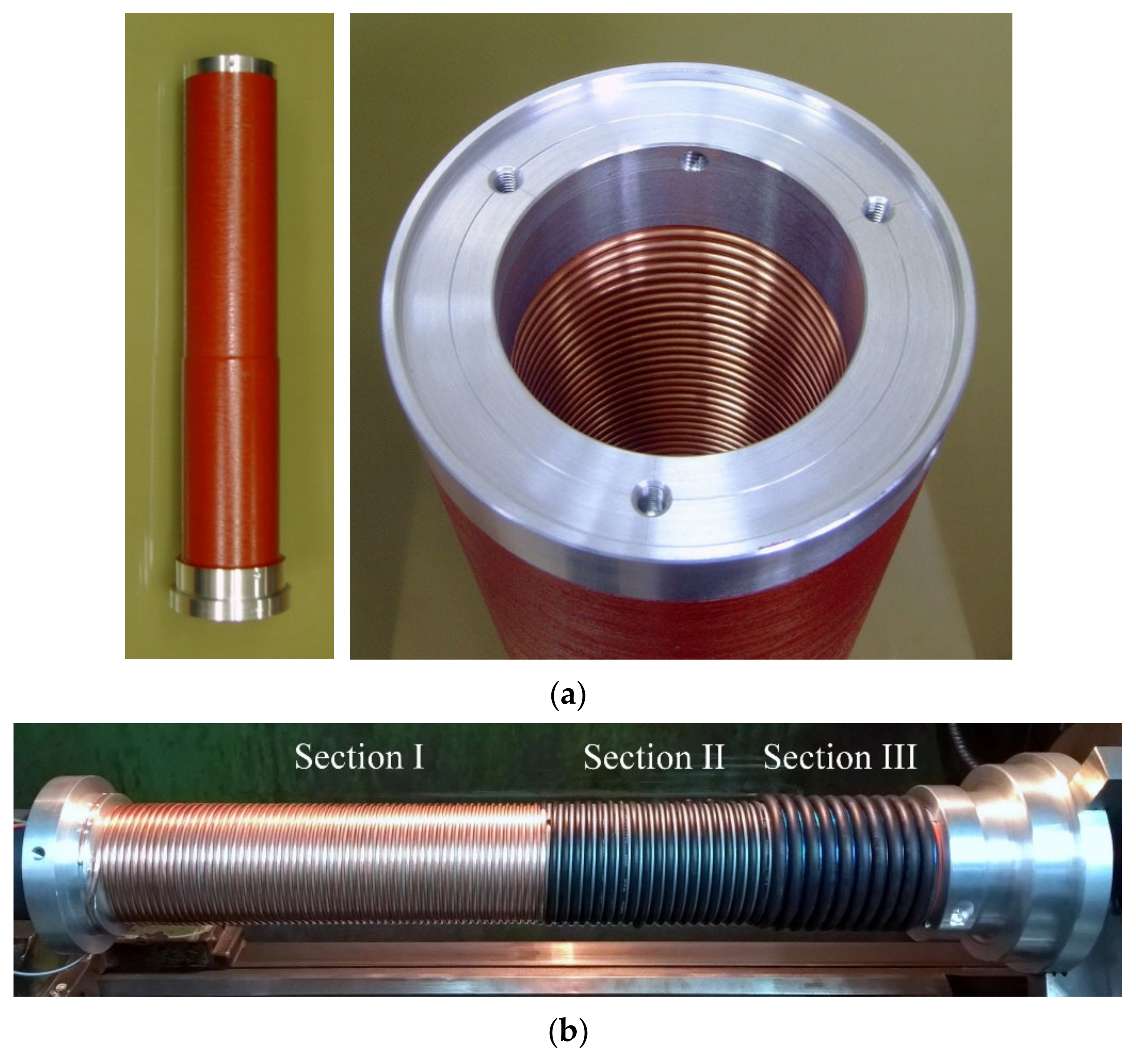
Figure 4 shows an example of a real model and a coil of a spiral FCG model with the parameters given in
Table 1. This coil has three sections, wound with copper wire of different diameters to ensure that when a current exceeding 100 kA is generated in its last turns, there will be no undesirable, significant increase in winding temperature and its deformation related to, for example, axial and radial components of electrodynamic forces. FCG coil is a key element of the generator structure, therefore, in order to properly select its parameters, a multi-criteria optimization process should be carried out in terms of the current amplification value or the shape of the generated current pulse [
62], the description of which, however, is not the purpose of this paper.
In order to properly select the parameters of the FF cooperating with the FCG, it is possible to use simulation methods. For this purpose, based on Equation (2), a dynamic FCG model has been created. The change in the inductance value of the FCG winding during the generation process has been determined on the basis of model simulation using the finite element method [
63].
In order to verify the correctness of the model, experimental tests of the generation process have been carried out in field conditions. As the FCG load, a coil with the same parameters as the PFS forming coil (with an inductance of 2.6 μH) has been used. A view of an exemplary test stand with FCG prepared for the test and after its explosion has been presented in
Figure 5.
The dynamics of FCG current generation process depends on two key factors, i.e., the detonation velocity of the driving explosives in the armature and the slope of the linear change in inductance of the generator winding
dL/
dx (related mainly to the model geometry), where
x is the short-circuit wavefront position along the FCG winding. In both cases, these parameters are limited by the physical properties of the explosives or the dimensions of the FCG model. Hence, the maximum slope of the current increase during the generation process reaches a maximum value of over a dozen kA/us [
24]. Moreover, during the generation process, the voltages on the circuit fragments do not exceed a few dozen kV (depending on the load parameters). Therefore, to measure the key electrical quantity, i.e., generated current waveform, it is possible to use transducers with an appropriate range and transmission band. During the experimental research, Pearson transducers and Rogowski coils have been used. The tests were carried out in field conditions, in which the FCG models were placed on an appropriate armor plate to limit the impact of an explosion on sensitive measuring equipment.
The summary of selected simulation results and experimental tests in the form of FCG current waveforms is shown in
Figure 6.
On the basis of the comparison in
Figure 6, it can be concluded that the created simulation model with very good accuracy reflects the operation of the real FCG both during the generation process and after its termination. The maximum relative error does not exceed 5% in relation to the maximum value. The developed and verified FCG simulation model has been implemented as the pulse generation system model during further research.
3. Forming Fuse for High-Power Pulse Forming System
3.1. Pulse Forming System Concept
The purpose of the pulse forming system is to adjust the pulse parameters to the load requirements. For this purpose, it usually increases the maximum power multiple times while reducing the pulse duration.
Electric-type PFS (e.g., Marx generator with forming line) can be a suitable source of HV pulses for systems less demanding in terms of power requirement and total pulse energy [
24,
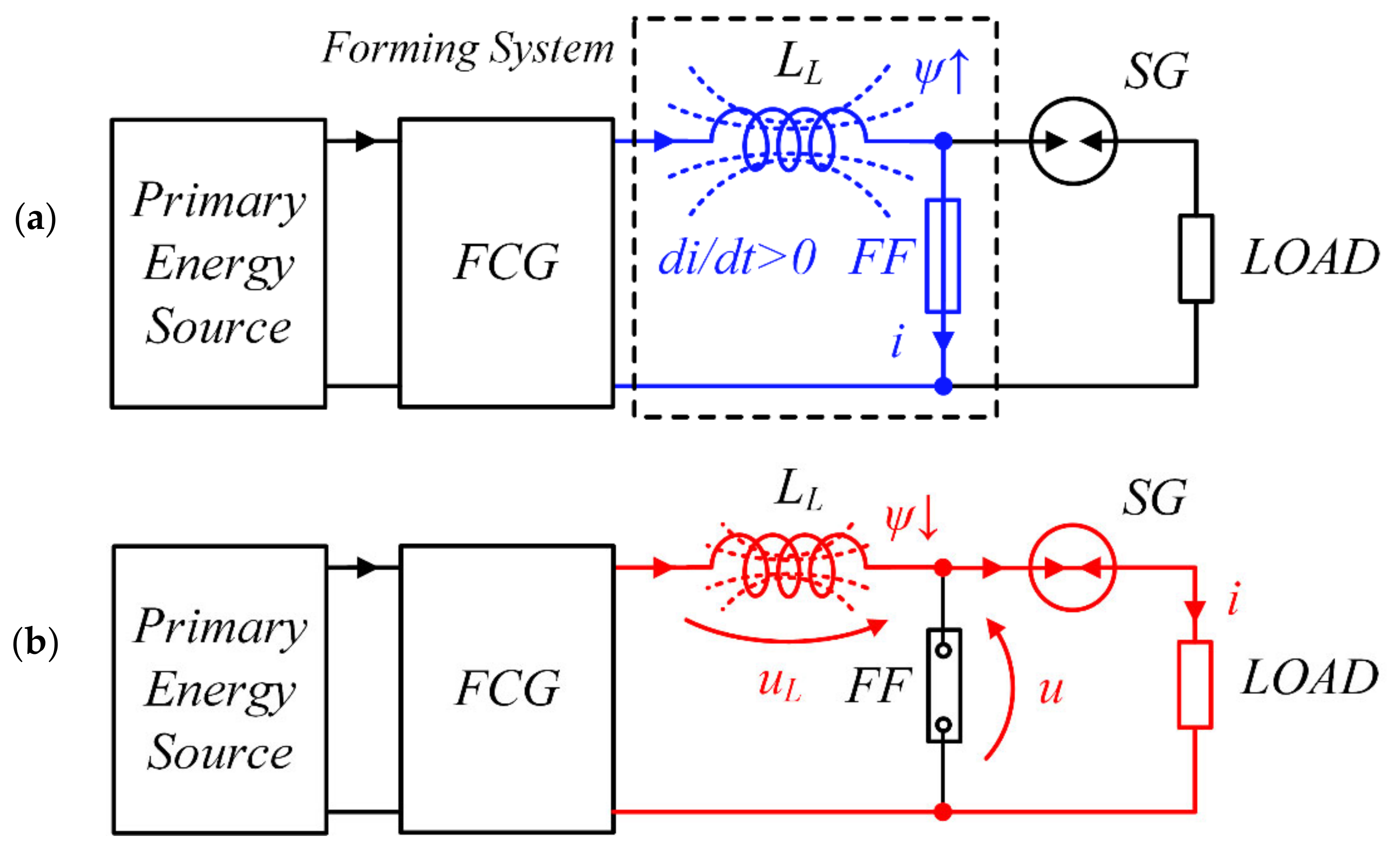
25]. Systems of this type are usually characterized by a significant output impedance, in the order of hundreds of Ω or more. In the case of loads with a low impedance value, which, in addition to ensuring an appropriate level of the pulse voltage, also require a significant current efficiency of the source, PFS with a higher power and energy density, i.e., based on the magnetic field energy accumulation process in a forming coil and forced rapid limitation of the coil current, which enables obtaining huge overvoltages (in the order of hundreds of kV) are far more suitable. The two-stage process of pulses forming in this type of systems has been shown schematically in
Figure 7.
In the first stage of PFS operation, the current value increases and the energy accumulates in the magnetic field of the forming coil LL. The low value of the fuse resistance in the short-circuit condition ensures the possibility of reaching a considerable value of the current, therefore it is possible to accumulate significant values of the magnetic field energy. The second stage of the pulse forming process consists of a rapid limitation of the current flowing in the circuit by the FF and its commutation to the load. Due to the fact that the load impedance usually reaches much higher values than the impedance of the other elements of the system, in order to achieve effective commutation, it is necessary to generate a very high overvoltage value uL(t) = LL·di/dt, which is possible only when ensuring adequate high steepness of current limitation by FF. Otherwise, a significant portion of the energy stored in the forming coil is dissipated in a fuse resistance.
Forming fuses (FF) are the dominant type of current interrupting devices in terms of current break times and speed of a full electric strength recovery used in PFS. The FF principle of operation is based on the rapid disintegration of a conductor or multiple parallel conductors, called fusible elements, as a result of the considerable-value pulse current flow. This electro-explosive disintegration is caused by a rapid increase of the fusible elements thermal energy to a value comparable to the metal sublimation energy [
14,
43,
64]. The rate of increase in resistance
dR/
dt during the FF disintegration reaches many hundreds of Ω/μs [
39,
51]. Due to the multiplication of the number of parallel fusible elements, FF have the ability to conduct a considerable value of currents, in the order of hundreds of kA. Therefore, the FF are an excellent solution for a high-speed limiting switch for the purpose of a high power pulse generation.
3.2. Fuse-Based PFS Laboratory Research
The efficiency of high-power pulse forming by the FF-based PFS, apart from the circuit parameters, is influenced by many fuse design factors, including:
cross-section area and the number of parallel fusible elements,
fusible elements material, geometry and length,
type and pressure of the medium filling the fuse chamber.
Therefore, the optimal selection of the above-mentioned FF parameters in order to ensure effective pulse forming process is a problem of non-linear multi-criteria analysis. In order to determine the selected FF parameters influence on the current limitation process and generation of significant overvoltage values, a number of laboratory tests have been performed.
An important design factor of the FF is the length
l of the used fusible elements. During the process of rapid fuse disintegration, as a result of which an overvoltage of hundreds of kV is generated, the radial expansion of fusible elements disintegration products takes place, which is related to the deionization process of the formed plasma channel. During the disintegration process, the plasma channel is affected by an high-intensity electric field, which may cause avalanche ionization of the channel and the arc discharge ignition, the appearance of which is a result of ineffective operation of the fuse and causes short-circuit of the PFS. Therefore, the length of the fusible elements should be selected so that the electric strength of the column prevents the arc ignition during and shortly after the HV pulse generation process. On the other hand, the fusible elements resistance resulting from their excessive length can limit the peak value of the current in the PFS circuit. Therefore, for the certain FF operating conditions, there is an optimal length of the fusible elements. In this context, the concepts of fuse length selection based mainly on the volumetric energy criterion [
22,
24,
40,
52] may not constitute appropriate design guidelines. The basic criterion for selecting the length of the fuse elements should be the electric strength of the fuse column not leading to the ignition of the arc discharge during the current limiting process. The quantification of this criterion is not the aim of this article. For the purposes of this study, the length of the fusible elements has been selected based on experimental research.
An essential design parameter of fuse systems is the type of medium filling the fuse chamber. In the case of FFs, in which the current of considerable value flows in a very short time, due to the adiabatic heating of the fusible elements, the process of heat exchange with the extinguishing medium does not occur. Hence, the main criterion to be taken into account when selecting the medium of the FF chamber is the electrical strength of the plasma channel formed after the fusible elements disintegration. The most frequently used medium are various types of electrically insulating gases, including sulfur hexafluoride SF
6 [
21,
22,
24,
65,
66]. In order to increase the electric strength of the fuse chamber during the pulse forming process, it is possible to fill the chamber with gas under increased pressure. In this study, SF
6 gas has been used at a pressure of approx. 5 bar.
The key parameters related to the operation of the FF are also the type and material of the used fusible elements. The available literature mentions wire or foil fuses made of materials with high conductivity (mainly silver or copper) or high specific melting energy, e.g., tungsten. The diameter of the single fusible elements used should guarantee an even cross-sectional current density distribution (related to the diffusion of the magnetic field inside the conductor) during the flow of pulse currents with high dynamics. The fusible elements made of calibrated high-purity silver (over 99.99% Ag) wire with a diameter of 0.125 mm wound spirally on an insulating support with a pitch resulting from the assumed length of the elements have been used.
As part of this work, a laboratory prototype of a forming fuse has been prepared, adapted to interrupt currents up to approx. 40 kA and to generate high voltage pulses on a forming coil. The conducted laboratory tests of PFS supplied from a battery of pulse capacitors have been aimed at developing design guidelines for a fuse model adapted to work with FCG. The PFS containing a forming coil with an inductance
LL = 2.6 μH and a FF with the parameters presented in
Table 2 has been supplied from a battery of pulse capacitors with a capacity of
C0 = 0.96 μF, charged by a high-voltage power supply up to initial voltage approx.
U0 = 50 kV. The capacitor discharge circuit was switched on with the use of a pressure trigatron (in which a sudden drop in a gas pressure causes the shorting discharge to ignite).
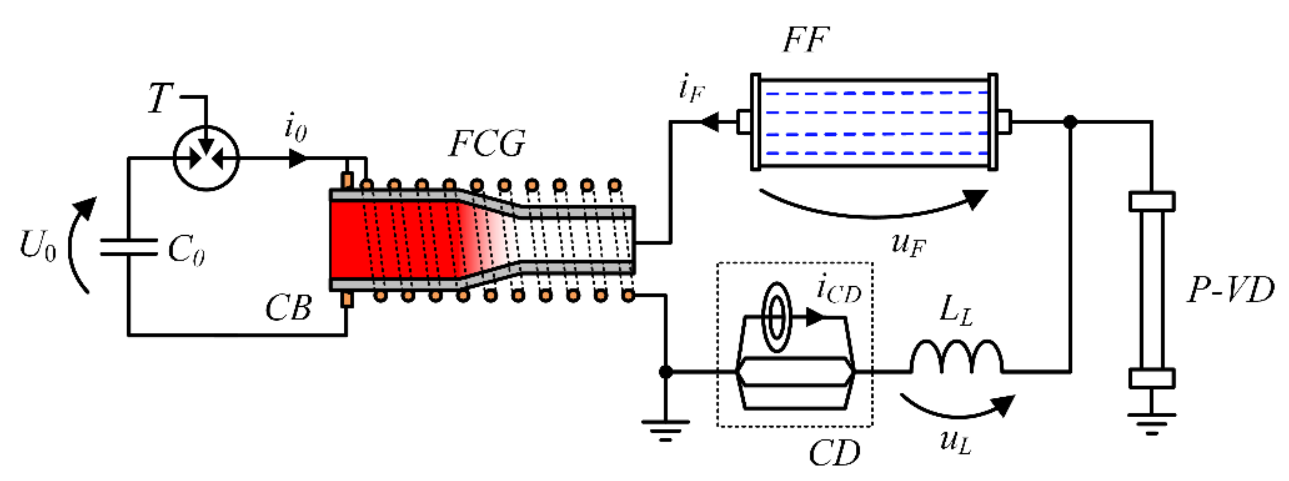
The current waveforms of the system were measured using a Pearson current transducer with the appropriate band (8 MHz) and maximum current range (40 kA), while the voltage—using a high voltage pulse divider with a frequency bandwidth of approx. 9 MHz and voltage range of 800 kV. The schematic diagram of the pulse forming test system with a FF has been shown in
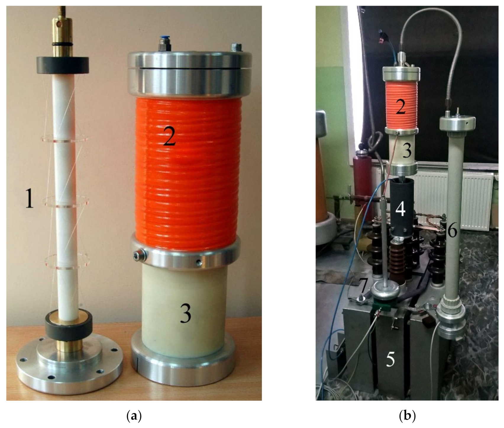
Figure 8, while the photographs of the FF model and the laboratory test stand have been shown in
Figure 9.
Regarding the structure of the test stand, it is worth noting the existence of a non-trivial problem of the of additional, significant voltage drops (in order of the kV) occurring on the fragments of the test circuit, resulting from the parasitic inductance of the main current path connections and the sudden current limitation by FF. The general guiding principle during the construction of the test stand should be to keep it compact in order to minimize these inductances.
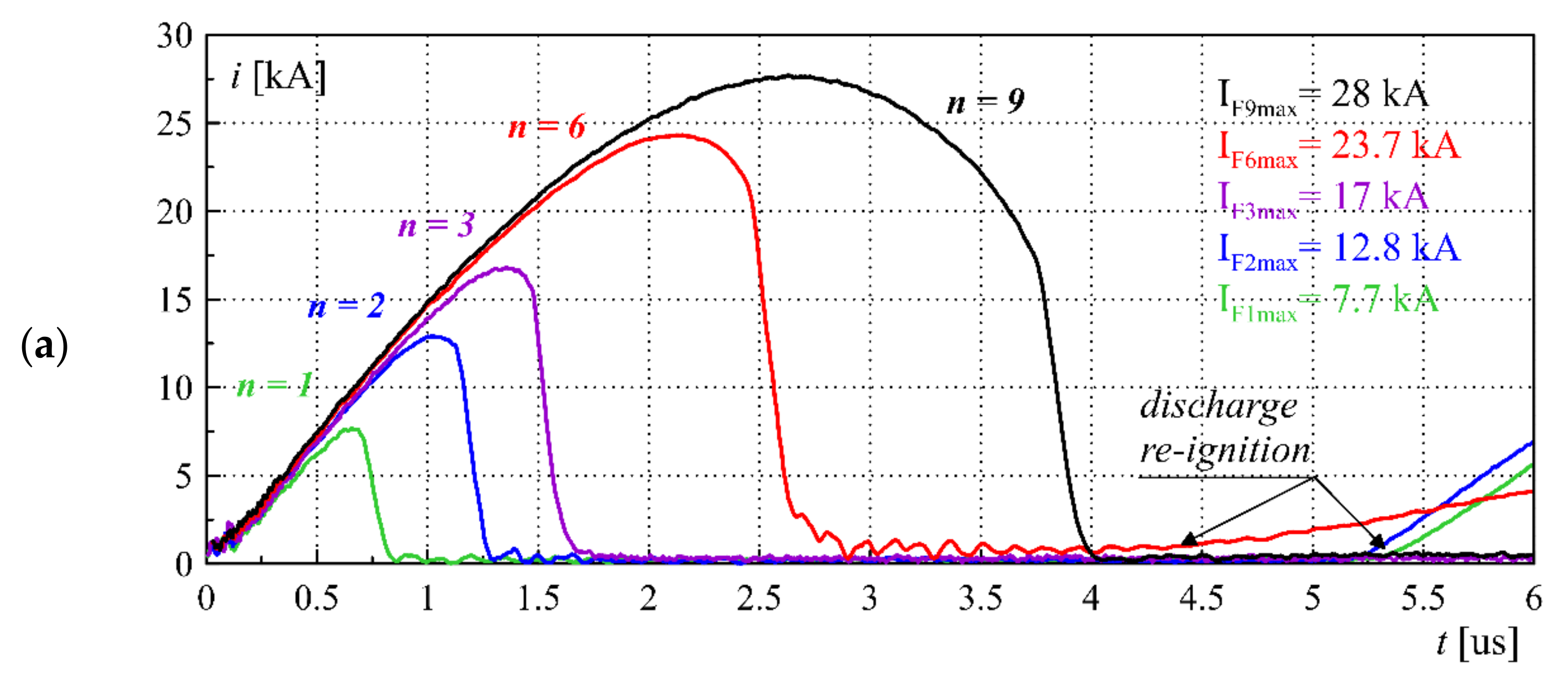
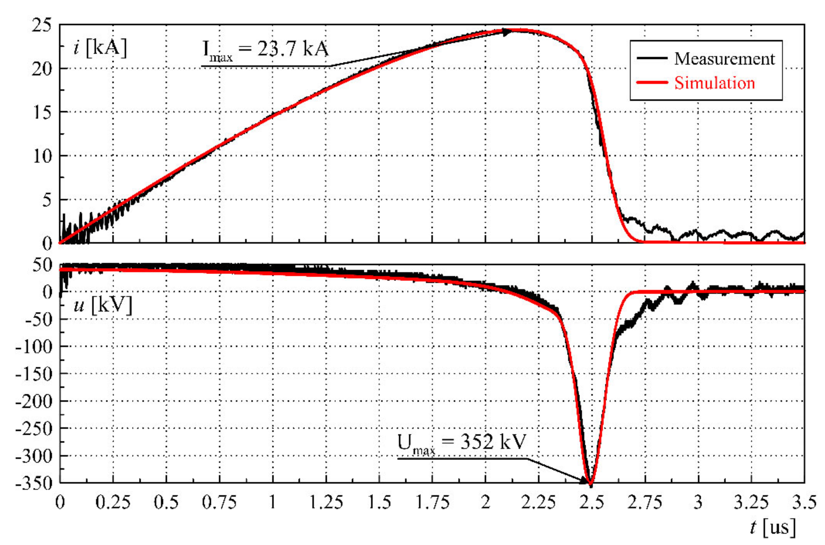
Figure 10 presents selected results of the FF-based PFS laboratory tests for a different number of applied fusible elements
n.
For a small number of fusible elements, a strong limitation of the maximum value of the forming coil current by the resultant resistance of the fuse occurs due to the fact that the fusible elements quickly reach the Joule integral value related to the melting and evaporation energy of the conductor material, the so-called pre-arc Joule integral. As a result, the fusible elements disintegrate less rapidly and the value of the formed overvoltage pulse is lower. When overestimating the number of parallel fusible elements for specific source parameters, i.e., capacitance
C0 and voltage
U0, their disintegration takes place after reaching the maximum value of the capacitor bank discharge current, i.e., during the falling edge of the current half-wave. The negative value of the current density rise steepness
dj/
dt in the fusible elements significantly reduces the dynamics of their disintegration, also limiting the value of the formed overvoltage. Therefore, there is an optimal number of parallel fuse elements (related to the equivalent cross-section of the fuse) for the specified source parameters, which guarantees optimal conditions for the pulse forming process. Assuming the adiabatic heating of the fusible elements of the FF due to current flow
i(
t)
, their optimal number
n for a given source current waveform can be determined using the Equation (3). In the case of PFS powered by a bank of pulse capacitors, the equation can be transformed into the form (4), depending on the parameters of the circuit
LL and
C0.
where:
tp—pre-arcing time of fusible elements disintegration,
KM—Meyer constant, specific Joule integral of the fusible material (for Cu:
KMCu ≈ (1.3 ÷ 1.4)·10
17 A
2s/m
4, and Ag:
KMAg ≈ (1.1 ÷ 1.2)·10
17 A
2s/m
4 [
67,
68,
69]),
S—cross-section of a single fusible element,
γ ≈ 0.85—correction factor taking into account the influence of the fuse resistance on the PFS current waveform. For current waveforms other than harmonics, e.g., FCG current, a numerical calculation can be used.
Table 3 summarizes the maximum overvoltage values and the maximum pulses power achieved by FF-based PFS based on a review of available literature solutions, including the parameters of the forming fuses.
Based on the above overview, it can be concluded that the designs of high-power pulse generation and forming systems based on FCG and electro-explosive forming fuses, which use fusible elements in the form of a calibrated well conducting wire, are a very advantageous combination in terms of the maximum obtained overvoltages, power density and single pulse energy. The forming inductance value, which determines also the load parameters for the primary source or the pulse generation system (e.g., FCG), is usually selected based on the need to provide the appropriate impedance (input and output) of the forming stage or appropriate parameters of the formed output pulse and should be determined at the stage of preliminary design assumptions. The most frequently used medium filling the forming fuse chamber is SF6 gas due to very beneficial electrical insulating parameters. It is worth noting that the upper limit of overvoltages generated in the FF-based forming systems is approx. 400 kV and results from the maximum dynamics of the fusible elements disintegration and the electric strength of the plasma column formed after their electro-explosion.
4. Simulation Model of Fuse-Based Pulse Forming System
On the basis of the FF laboratory tests, an extended resistive quasi-empirical model of a fuse has been formulated under the conditions of a homogeneous electro-explosion of fusible elements, i.e., assuming that the applied energy density meets the conditions necessary for the process of fusible elements disintegration to take place uniformly along their entire length. Such assumptions make it possible to adopt an equivalent circuit model of a FF with the use of lumped elements. The basis of the adopted concept is the empirical model proposed in [
24], based on the variable resistivity
ρ(
h) of the fusible material as a function of the specific Joule integral related to the square of the equivalent cross-section of the fuse elements
h(
t), based on the Formula (5).
The value of the FF resistance can be determined on the basis of the relationship (6).
The fusible material resistivity
ρ should include three stages of fusible elements disintegration, i.e., pre-heating, melting and the proper electro-explosion process. The model should also provide an appropriate representation of the processes occurring in the plasma channel after the fusible elements disintegration and after the current limitation to zero. Based on the results of laboratory tests, the model has been extended to the form (7), in which an additional factor describing the change in plasma channel resistivity after the fusible elements disintegration has been formulated.
where:
ρ0—initial resistivity of the fusible material at ambient temperature (for Ag:
ρ0Ag = 1.59×10
−8 Ωm),
A,
B,
C—coefficients describing the dynamics of the disintegration process, depending mainly on the type of the fusible material [
21,
22,
24] determined on the basis of extensive experimental research,
ρk—fuse equivalent resistivity at the moment of a homogeneous plasma channel formation,
—derivative of the plasma channel resistivity after the fusible elements disintegration,
hp—pre-arcing Joule integral related to the Meyer constant,
hk—Joule integral at the moment of a homogeneous plasma channel formation reached at the time
tk.
The first term of expression (7) is valid for the value of the specific Joule integral of the fusible elements h(t) (5) lower than the pre-arc integral hp and approximates the process of the initial increase in the fusible material resistivity in the solid phase, during the melting process and in the liquid phase of the material. The relative increase in the resistivity at this stage is dictated by the value of the coefficient A. The fusible elements resistivity in the superheated liquid form is in the range of twenty to thirty times the initial value ρ0. The value of the B coefficient determines the resistivity increase rate during the fusible elements melting and determines the initial stage of the current limitation process.
When the fusible elements reach the pre-arcing state h(t) = hp, i.e., at the moment just before disintegration, the resistivity is described by the exponential term of the relationship (7), which causes a significant increase in the fuse resistivity growth rate. This component is characterized by the exponent coefficient C and associated with the transition of the material from the superheated liquid phase to the plasma state as a result of the fusible elements electro-explosion, as a result of which the process of rapid current limitation to zero is initiated.
The model based on the above-described stages of the fusible elements disintegration does not take into account the process of radial expansion of the fuse plasma channel after the fusible elements explosion and after the current limitation to zero. Due to the lack of a further increase in the specific value of the Joule integral h(t), there is no further increase in the plasma channel resistivity. Hence, it is necessary to supplement the model with an additional term that takes into account the process of the resistivity increase of the plasma channel due to the inertia of its radial expansion process.
Based on the literature data [
47,
53,
75,
76], an assumption has been made that the process of the equivalent plasma channel resistivity increase after the fusible elements electro-explosion takes place with a certain speed, resulting from the explosion dynamics and the plasma channel inertia and it can be determined numerically, using the magnetohydrodynamic (MHD) model [
47,
53,
54,
77,
78]. However, this would require coupling the circuit model with the MHD field model. Based on the representative results of measurements and simulation of the plasma channel expansion after the fusible elements disintegration, the free speed of the channel expansion can be accurately approximated by the exponential component described by the time constant
τMHD defined as (9) [
79,
80,
81], on this basis of which the plasma channel resistivity derivative
after the fusible elements electro-explosion has been determined:
where:
—resistivity increase derivative since at the moment of the homogeneous plasma channel formation,
t −
tk—time since the formation of the plasma channel.
where:
r0—initial radius of the fusible element,
μ0—vacuum magnetic permeability,
m0—mass of the single fusible element,
V0—initial volume of the fusible element,
Bmax—maximum value of the magnetic flux density at the moment before the fusible elements disintegration (10).
The hk coefficient value and the corresponding value of have been determined numerically at the inflection point of the specific Joule integral h(t) increment, i.e., when the second derivative reaches a negative value at the moment of the maximum dynamics of the fusible elements disintegration.
The material and environmental coefficients values
A,
B,
C have been determined using the approximation method on the basis of numerous experimental tests of the forming fuses in laboratory conditions.
Figure 11 presents the selected characteristic of the relative increase in resistivity as a function of the fusible elements Joule integral specific value along with the approximation using model (7). The curves have been determined for the optimal number of fusible elements in different variants of the pulsed capacitors battery
C0 capacity, i.e., 0.16 μF, 0.32 μF, 0.48 μF and 0.96 μF. The uncertainty range of the coefficient values for the performed laboratory tests has been also presented. The values of the coefficients adopted in the numerical model (
Table 4) have been determined as the mean values for the variability range.
The model has been implemented in Matlab Simulink software and tested for various of FF and capacitor banks parameters.
Figure 12 shows a representative comparison of the current and voltage waveforms obtained through experimental tests and simulations using the model (7). The proposed extended model of the fusible elements disintegration under the conditions of a homogeneous electro-explosion allows for a much better representation of the falling slope curve of the current waveform and the formed voltage pulse waveform.
The maximum error of approximation using the model (7) in relation to the results of PFS laboratory tests with a FF for different parameters of the pulse capacitor bank and a different number of fusible elements does not exceed 3%. From the perspective of the integrated high-power pulse generation and forming system optimization, it is crucial to properly select the appropriate number of FF parallel fusible elements as a function of the Joule integral value related to the FCG current generation process as it clearly results from laboratory tests (
Figure 10). The use of the FCG as the first stage of the high-power pulses generation and forming system enables a significant increase in the power and energy of the pulse and ensures high compactness of the entire system. However, the strong mutual coupling of the FCG current generation process and the FF operation makes it impossible to determine analytical dependencies for the selection of optimal fuse parameters. It should also be mentioned that the experimental tests with FCG constitute a significant organizational challenge due to the presence of high explosives. Therefore, the best solution to the problem of selecting the parameters of the FF (mainly the number of fusible elements) are appropriate numerical simulations.
5. Experimental Studies of the Integrated High-Power Pulse Generation and Forming System
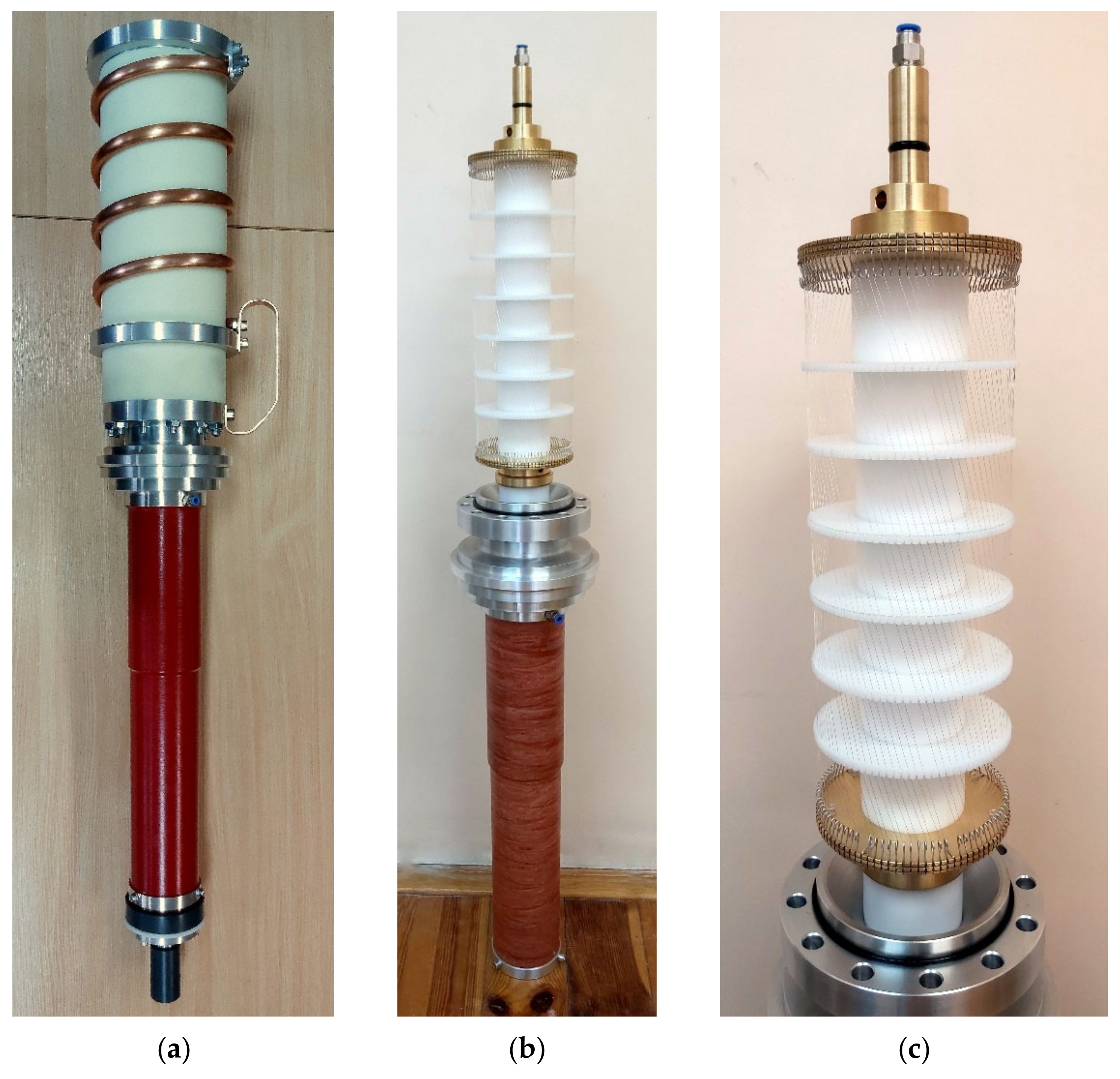
The final product of the work presented in this manuscript is the integrated and compact high power pulse generation and forming system containing an FCG and the FF-based PFS. The integrated system tests have been carried out in field conditions due to the destructive nature of the FCG operation. Based on comprehensive simulation tests, the optimal number and length of FF fusible elements for a specific FCG design have been determined, i.e., 84 silver fusible elements with a length of 360 mm and a diameter of 0.125 mm. The fuse chamber has been filled with SF
6 at a pressure of approx. 5 bar. Photographs of the integrated and compact high-power pulse generation and forming system along with a view of the inside of the FF chamber have been shown in
Figure 13.
Figure 14 presents a schematic diagram of the integrated system with the most important measuring transducers included.
The primary energy source used during the field tests was a pulse capacitor battery with a capacity C0 = 100 μF charged to the initial voltage U0 = 10 kV which constitutes a source energy of E0 = 5 kJ. The discharge circuit of the pulse capacitor bank has been triggered by an argon-oxygen spark trigatron stimulated from the optical fiber synchronization system and special detonating delay cord of a specific length (to ensure detonation of the FCG igniter at the peak of the capacitor bank discharge current half-wave).
Due to the very high dynamics of the current limitation to zero by the forming fuse and significant current maximum values, the direct use of conventional current transducers is difficult. Therefore, to properly measure the current waveforms during the operation of FCG and FF, the measurement method based on a pulse current divider and numerical compensation of the waveforms described in detail in [
82] has been used, which allowed to reduce the current measurement error below 2.5%. The current waveforms inside the pulse current divider have been measured using Pearson transducers and Rogowski coils (to ensure the necessary redundancy during a single test).
The voltage on the forming coil at the end of FCG generation process (when its entire winding is shorted) corresponds to the value of the voltage on the forming fuse and during the field tests has been measured with the use of pulse high-voltage divider and verified with a D-DOT type electric field probe.
It is worth noting that many other parameters, including non-electrical ones, have been also measured during the tests, e.g., the speed of the explosives detonation wave propagation inside the FCG armature (using fiber-optic and piezoelectric transducers) or the measurement of electromagnetic noise occurring as a result of the FCG generation process (due to the shortening of successive turns of the FCG winding) with electromagnetic field probes. These measurements were aimed at enabling precise synchronization of the electrical quantities waveforms with the mechanical processes occurring inside the FCG, including determination of the expected FCG generation process termination time in relation to the FF operation. The determined speed of the detonation wave linear propagation of a hexogen-based (RDX) explosive with a binding material was 7.36 ± 0.1 mm/μs.
Figure 15 presents a fragment of the high-current and high-voltage test stand of integrated high-power pulse generation and forming system using FF and FCG, including the protective 25 mm thick armor plate installed to protect the fuse and measuring transducers against the effects of the FCG explosion.
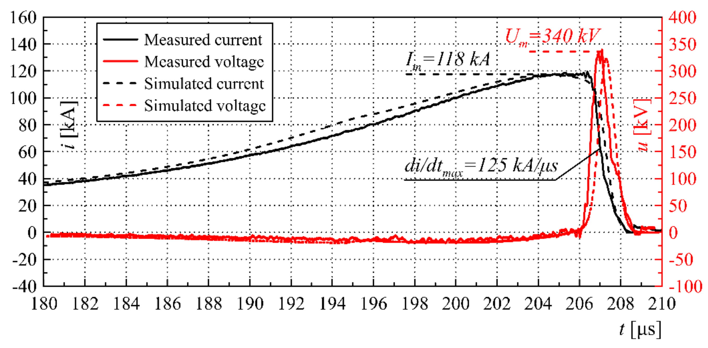
Figure 16 presents a selected comparison of the experimental and simulation tests results in the form of FCG and FF current waveforms and the voltage on the forming coil u (in close-up for the FF operation process).
During the tests, the maximum value of the overvoltage on the forming coil
Um = 340 kV has been achieved with the maximum generated current at the level of
Im = 118 kA. The results of the simulation tests coincide to a large extent with the results of the experimental results, which proves that the physical phenomena are sufficiently represented by the described FCG and FF models. The maximum simulation error in terms of current prediction reached approx. 5%, and voltage—3.6%. Subsequent studies of pulse generation and formation processes could help to further minimize the models errors. Based on the experimental tests confirmed by simulations, it can be concluded that due to the optimal selection of FF parameters, the disintegration of the fusible elements occurred just before the end of the FCG current generation process (anticipated at the moment
tGk = 207.8 μs), which resulted in the achievement of a significant pulse power value.
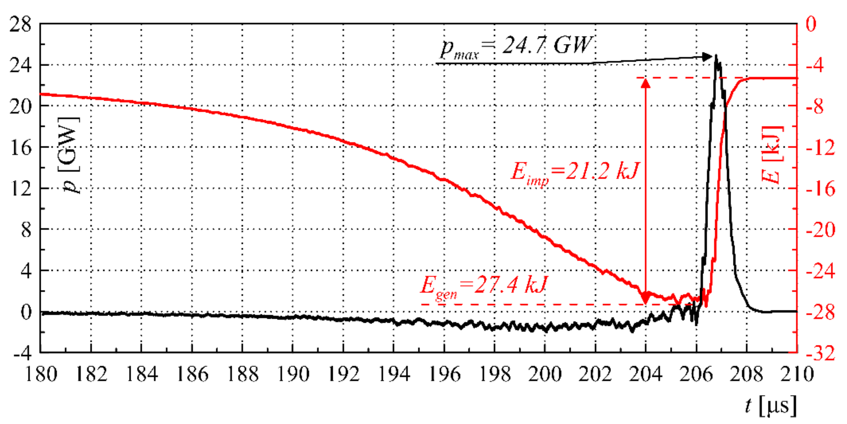
Figure 17 shows the waveforms of the instantaneous power
p(
t) generated by the system and the energy
E(
t) generated by the integrated high-power pulse generation and forming system during its operation along with significant characteristic values.
The maximum value of the pulse power achieved as a result of the tests was
pmax = 24.7 GW during approx. 1.5 μs.
Figure 17 shows that the pulse forming process using FF with appropriately selected parameters provides the energy that can be transferred to the load at the level
Eimp = 21.2 kJ and has quite high efficiency
η = Eimp/
Egen ≈ 77%. It is also worth noting that the FCG generation process, according to the research results, causes a significant energy gain in relation to the energy stored in the primary energy source (pulse capacitor bank)
kE =
Egen/
E0 ≈ 550%. The observed difference
Egen—
E0 in the pulse energy available after the generation process results from the presence of additional chemical energy stored in the explosives driving the generation process. This fact is an extremely valuable feature of FCG-based systems, which is not available in other types of solutions.
Table 5 presents a literature summary of the high-power pulses generation and forming systems parameters with the use of various technologies. It should be noted that only systems with a compact design that can be used in field conditions have been taken into account in this comparison.
Based on the summary presented in
Table 5, it can be deduced that the high-power pulse generation and forming systems based on FCG and electro-explosive FF (in particular in the form of an integrated system) have the most favorable parameters in terms of power density and pulse energy, even by two orders of magnitude exceeding the voltage-type generation systems parameters.
6. Conclusions
High-power pulse generation and forming systems based on FCG and FF enable achieving power and energy density unavailable to other solutions (e.g., based on Marx generators and forming lines). In the proposed system, the power values of 25 GW with a voltage of about 340 kV and current in order of 120 kA have been achieved in a volume of just 0.022 m3, which results in a power density of 1.12 TW/m3 and an energy density of 960 kJ/m3 which are many times (even by two orders of magnitude) greater than those achieved by voltage-type generators. It is worth noting, however, that the described system topology, due to the destructive nature of the FCG operation, is for single use only. However, in many applications, e.g., military, the generation of a single but very high power pulse is a sufficient condition for the use of this type of system.
The extended quasi-empirical model of the FF together with the numerical model of the FCG operation reflect the nature of the phenomena occurring in the system with a very high accuracy and enable the selection of optimal system parameters at the early stages of design. This fact is particularly important considering the one-off nature of FCG tests and the high level of organizational complexity of such tests due to the presence of high explosives.
The high steepness and the maximum voltage and power values of the generated pulses are the features that allow the system to be used in many fields of science and technology, e.g., for powering pulsed laser sources, pulse microwave radiation systems based on e.g., vircators, in nuclear physics and particle physics applications as well as for emulating the effects of atmospheric discharges (LEMP) or nuclear pulses (NEMP) on electrical and electronic devices and systems. It is worth noting that by using the PFS (based e.g., on electro-explosive FF), it is possible to significantly shorten the pulse duration time, up to the order of hundreds of ns, which enables effective mapping of the upper frequency band and power density [
83] of the NEMP, especially in field or marine conditions, during special use (e.g., military grade) systems tests, where it is impossible to transport extensive equipment based on, e.g., Marx generators.


