Abstract
Inlet temperature is vital to the thermal efficiency of gas turbines, which is becoming increasingly important in the context of structural changes in power supplies with more intermittent renewable power sources. Blade cooling is a key method for gas turbines to maintain high inlet temperatures whilst also meeting material temperature limits. However, the implementation of blade cooling within a gas turbine—for instance, thermal barrier coatings (TBCs)—might also change its heat transfer characteristics and lead to challenges in calculating its internal temperature and thermal efficiency. Existing studies have mainly focused on the materials and mechanisms of TBCs and the impact of TBCs on turbine blades. However, these analyses are insufficient for measuring the overall impact of TBCs on turbines. In this study, the impact of TBC thickness on the performance of gas turbines is analyzed. An improved mathematical model for turbine flow passage is proposed, considering the impact of cooling with TBCs. This model has the function of analyzing the impact of TBCs on turbine geometry. By changing the TBCs’ thickness from 0.0005 m to 0.0013 m, its effects on turbine flow passage are quantitatively analyzed using the proposed model. The variation rules of the cooling air ratio, turbine inlet mass flow rate, and turbine flow passage structure within the range of 0.0005 m to 0.0013 m of TBC thicknesses are given.
1. Introduction
For high thermal efficiencies, modern gas turbines require significantly high turbine inlet temperatures, which have approached 1600 °C in the latest H-class and J-class gas turbines used for power generation [1]. As a result, turbine blades experience very critical environments inside gas turbines. Limited by the melting temperatures of the blades, many technology advances have been achieved to allow gas turbines to maintain high turbine inlet temperatures, such as improved cooling techniques and the development of thermal barrier coatings (TBCs).
Extensive cooling of air has a significant impact on gas turbine performance and adds challenges to the analysis of gas turbine performance. Many studies have been conducted in the field of turbine cooling. El-Masri carried out a second law analysis of gas turbine combined cycles [2] and a detailed thermodynamic analysis of cooling turbines in single cycles [3] and combined cycles [4], which laid the foundation for later researchers to develop more detailed thermodynamic models to analyze the performance of cooling turbines. Young et al. carried out a general thermodynamics analysis of air-cooled gas turbines [5], calculated the coolant flow rate, and quantitatively gave the cooling loss caused by the cooling air [6]. In the cooling model established by Walsh et al. [7], the cooling air was divided into working and non-working cooling air, and an empirical formula related to the cooling air mass flow rate and the turbine inlet temperature was proposed. Chiesa et al. [8] proposed a calculation method for the coolant mass flow rate of steam cooling, and compared the output parameters of gas turbines with open air cooling and closed steam cooling.
Some researchers have concentrated on the performance improvement of gas turbines using cooling techniques. Brown et al. [9] considered air extraction in the middle stage of the compressor for optimizing the cooling air mass flow rate to achieve the best performance of the gas turbine. Moon et al. [10] proposed coolant intercooling to reduce the coolant temperature and improve the gas turbine performance further.
There are some studies that clearly show the significance and necessity of the consideration of cooling for gas turbine performance analysis. Sahu et al. [11] reported a comparative analysis of basic and complex cooled gas turbine cycles and showed that intercooled recuperated gas turbine cycles offered higher efficiencies compared to basic gas turbine cycles. Salpingidou et al. [12] showed that both the thermal efficiency and the specific fuel consumption of recuperative gas turbines cycles are affected when turbine blade cooling is taken into account.
The use of TBCs adds new characteristics to the heat transfer process. TBCs made of low thermal conductivity ceramics are highly advanced materials that are applied to metallic surfaces. TBCs cover the blade substrate and become a part of the blade, which changes the overall thermal conductivity of the blade wall. Okajima et al. [13] discussed the development and verification of TBCs utilizing Mitsubishi Heavy Industries’s own power plant. Ogiriki et al. [14] selected high-pressure turbine blades as the life-limiting component of gas turbines and analyzed the impact of TBC degradation on gas turbine engine creep life. Sahith et al. [15] reviewed the development and analysis of TBCs for gas turbines, including the different material options for the substrate, bond coat, and top coat, and the methods implemented to apply the bond coat and top coat—with the analysis of the TBCs performed according to various criteria and conditions. Wu et al. [16] reviewed the properties of new ceramic materials and elaborated the working principles, merits, and demerits of the main technologies employed for TBCs used on gas turbines.
The effects of different TBC thicknesses have been investigated in recent years. Gurrappa et al. [17] conducted hot corrosion studies on various TBC thicknesses to determine their optimum thickness. The effects of TBC thickness on temperature and stress distribution over the blade body were investigated by Ziaei-Asl et al. [18]. Sankar et al. [19] optimized the TBC thickness for gas turbine blades, with consideration to temperature, stress, and cost, and found out that partially stabilized zirconium is the best material for TBCs. Nagabandi et al. [20] proposed an innovative method for increasing TBC thickness locally in hotspot regions to enhance the thermal insulation and life capabilities of combustor tiles. Huang et al. [21] carried out conjugate heat experiments to investigate the combined effects of the internal element layout, TBC thickness, and coolant amount on the metal and TBC surface temperature. Frackowiak et al. [22] determined the temperature distribution inside turbine blades in which the external surface is coated with different thicknesses of TBCs. Radhakrishnan et al. [23] performed a thermal analysis and creep lifetime prediction based on different TBC thicknesses coated on combustor liners.
Yunus et al. [24] summarized the current studies on TBC-assisted cooling air systems on gas turbines. Existing studies have mainly focused on the materials and mechanisms of TBCs and the impact of TBCs on turbine blades. However, these analyses are insufficient for assessing the overall impact of TBCs on the turbine—for instance, the impact of TBCs on the turbine flow passage. The flow passage is one of the main areas of the turbine, of which, the structure is affected by the blade length and rotor radius, and has an impact on the gas mass flow rate as well as the gas turbine efficiency. The impact of cooling with TBCs on the turbine flow passage structure still needs to be studied. The contribution of this paper is in analyzing the impact of TBC thickness on the overall turbine, especially on turbine flow passage, in a novel perspective. Combining aerothermodynamics calculations and turbine blade cooling with TBCs, a mathematical model is proposed. Furthermore, the impact of TBC thickness on the cooling air ratio, turbine inlet mass flow rate, and turbine expanding angle are also quantitatively analyzed based on the proposed model.
2. Problem Description
In turbines with cooling technologies, the cooling air is fed into the turbine stage-by-stage. Taking a 4-stage turbine as an example, except for the last-stage rotor blades, cooling air is applied to all the stator blades and rotor blades—as shown in Figure 1. It can be observed that the volume flow rate in the turbine is changed not only by gas expansion but also by the injection of cooling air. In the turbine design process, the geometric parameters of the turbine, such as the blades’ heights and lengths, depend closely on the volume flow rate. As a result, the existence of cooling air has a direct influence on the turbine’s geometry. The application of TBCs enhances the cooling effect, which reduces the need of cooling air to maintain a constant blade substrate temperature—but to what extent do TBCs affect turbine geometry? This still needs to be analyzed quantitatively.
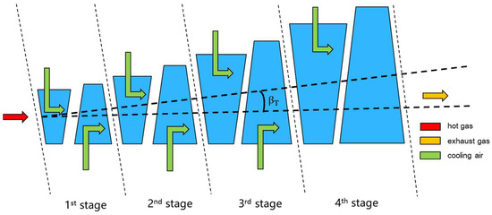
Figure 1.
Schematic Diagram of a Turbine with Cooling.
The turbine expanding angle is taken as the parameter describing the turbine’s geometry. Its definition is shown in the following formula:
where , , and L are the turbine expanding angle, the length of the last stage blade, the length of the first stage blade, and turbine flow passage, respectively.
3. Mathematical Model
3.1. The Heat Transfer Model of Turbine Cooling
The hot gas, at a high temperature, passes through the static blade, impacts the vane on the rotor, and converts the internal energy of the gas into mechanical energy of the rotor. In the heat transfer process, the blades absorb energy from the high temperature flue gas—mainly by means of radiation heat transfer and forced convection heat transfer—while the energy of the blades is transferred to a cylinder in the form of radiation, and the blades are cooled by forced convection of the cooling air. Finally, a small amount of heat is transferred to the axles or cylinders by conduction and to the flue gas in the form of radiation.
To calculate the heat transfer, the following hypotheses are made in this model:
- The heat absorption and release of gas in the turbine blades is a balanced process operating under normal working conditions, and can be regarded as a steady-state process.
- As the blade is hollow and the cooling air flows through the blade, the curvature of the blade is not very large, and the thickness of the blade is very small relative to the length and width of the blade; as such, it can be regarded as one-dimensional heat transfer [25].
- In the convective heat transfer between the blade’s outer surface and the high-temperature gas flow, as well as between the blade’s inner surface and the cooling air flow, the boundary condition is the constant blade surface temperature.
- The ratio of the inner and outer surface area of the blade can be adjusted in the turbine’s design, which is simplified in this paper. The inner and outer surface areas of the blades are considered equal.
- The blade and the cylinder can be regarded as grey bodies, and the blade’s outer surface area is much smaller than that of the cylinder.
In this study, the impacts of TBCs were taken into account. TBCs with a low thermal conductivity were deposited onto the surfaces of high temperature-resistant metals or superalloys, which provide thermal insulation to metallic components from the hot gas stream in gas turbines [26]. Figure 2 shows the structure of a typical TBC. The use of TBCs is one of the key factors that enable the gas turbine to operate at high temperatures above the melting temperature of superalloys, thereby improving the performance of the gas turbine. Figure 3 shows the temperature distribution of the blade wall. It can be observed that TBCs reduce the temperature of the blade substrate greatly.
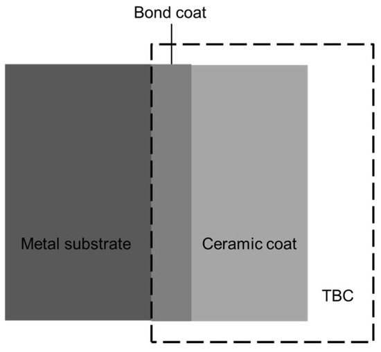
Figure 2.
Structure of a typical thermal barrier coating.
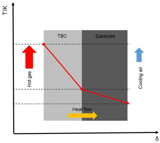
Figure 3.
The temperature distribution of a blade wall.
The Newton cooling formula, Fourier’s law, and Stephen Boltzmann’s Law are used to describe convection heat transfer, heat conduction, and radiation heat transfer, respectively [27].
The equations to describe the endothermic process of the turbine blade are described as follows:
where is the convection heat transfer flux between the high-temperature gas flow and the blade’s outer surface; is the convective heat transfer coefficient that ranges from 100 to 150 , according to previous design experience [25]; is the log mean temperature difference (LMTD) between the high-temperature gas flow and the blade’s outer surface; is the temperature of the blade’s outer surface; is the average temperature of the high-temperature gas; and are the temperature of the high-temperature gas at the element stage inlet and outlet, respectively; is the radiative heat transfer flux between the high-temperature gas flow and the blade’s outer surface; and are the blackness of the high-temperature gas and the blade, respectively; and is the absorptivity of the blade, whose value is the same as the blackness of the blade at the same temperature.
The equations to describe the heat dissipation process of the turbine blade are described as follows:
where is the convection heat transfer flux between the cooling air flow and the blade’s inner surface; is the convective heat transfer coefficient that ranges from 50 to 100 according to previous design experience [25]; is the log mean temperature difference (LMTD) between the cooling air flow and the blade’s inner surface; is the temperature of the blade’s inner surface; and are the temperature of the cooling air at the cooling channel inlet and outlet, respectively; is the radiative heat transfer flux between the turbine cylinder and the blade’s outer surface; is the temperature of the turbine cylinder; is the blackness of the cylinder; and and are the area of the blade’s outer surface and the cylinder, respectively. According to the hypotheses, is much smaller than , .
The equations of the heat conduction between the inner and outer surface of the blade are described as follows:
where is the heat conductive flux; is the heat conductivity coefficient; is the thickness; the subscripts and denote the TBCs and substrate, respectively; and is the temperature of the coating–substrate interface, where the temperature is highest in the substrate.
After obtaining the heat transfer flux, the heat balance can be described as follows:
There are three independent equations in total. The heat transfer calculation can be finished with the above formulae and some known conditions.
It can be noted that the above discussion is for cases where TBCs are applied. If there are no TBCs—that is, the thickness of the TBCs are 0—the middle term of Equation (6) has no physical significance, because the denominator becomes 0. In fact, in this case, the temperature of the coating–substrate interface and the temperature of the blade’s outer surface are the same temperature. The formula for the heat conductive flux is as follows:
3.2. Aerothermodynamics Model of Turbines Considering Cooling with TBCs
The aerothermodynamics calculation of axial-flow multistage turbine design contains 5 parts: parameter estimation, flow pattern calculation, thermodynamic calculation, geometric calculation, and verifying calculation—as shown in Figure 4 [28]. The following items are needed in the aerothermodynamics calculation: inlet temperature, inlet pressure, mass flow rate, outlet pressure, revolving speed, and some thermal properties of the working medium.
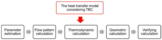
Figure 4.
Calculation process of turbine aerothermodynamics, considering cooling with TBCs.
(1) In parameter estimation, the number of element stages, the total enthalpy drop, the outlet temperature, the average diameter, and the blade length of the last stage, etc., will be obtained. In this study, a 4-stage turbine is taken as an example.
(2) In the flow pattern calculation, the meridian plane air flow channel pattern and the flow pattern can be adjusted. The meridian plane air flow channel pattern includes the equal inner diameter scheme, equal outer diameter scheme, equal average radius scheme, etc. The flow pattern refers to the changing rules of the parameters along the radial direction, generally including the equal circulation flow pattern, equal work flow pattern, etc. In this study, the equal inner diameter scheme and equal circulation flow pattern were selected, as in Equations (10) and (11), where is the diameter of the rotor hub, is the circumferential component of the high-temperature gas absolute velocity, and is the radius. This step is for calculating the velocity diagram and the actual enthalpy drop corresponding to different radii—that is, for obtaining the main parameters along the radial direction. Several radii are selected between the rotor radius and the radius of the last stage blade tip.
(3) The thermodynamic calculation is the main part of this process, which needs to be calculated stage by stage. This step is for calculating all the thermal parameters at all the radii selected in the flow pattern calculation on the characteristic sections 1–1 and 2–2 in all the stages, and for obtaining the blades’ lengths. The heat transfer model, considering cooling with TBCs, is applied. As shown in Figure 5, the cooling air mixes with the main stream at the stage outlet, which makes the mass flow rate larger and the temperature lower than that without the cooling air. The outlet gas flow rate and the outlet temperature can be obtained by the following equations:
where is the outlet mass flow rate, is the inlet mass flow rate, is the cooling air mass flow rate, is the enthalpy at temperature T, is the outlet temperature when there is no cooling air, is the blade length, is the density of the high-temperature gas, and is the axial component of the high-temperature gas absolute velocity.

Figure 5.
Schematic diagram of an element stage.
The parameters of cross-section 2–2 of the upper stage are taken as the parameters of cross-section 0–0 of the next stage. Once the inlet parameters of the first stage are given, the outlet parameters of the last stage can be obtained. The conservation of mass is used to determine the length of each stage blade.
(4) In the last step, the outlet parameters of the last stage are obtained, including the pressure. This pressure is a calculated value of the turbine outlet pressure. It is compared with the value of the turbine outlet pressure required by the design. If the error is within the allowable range, the next step of the calculation proceeds.
(5) The geometry calculation is for obtaining the width of the blades, the total length of the turbine, and the expending angle of the turbine. The geometry parameters can be obtained by the following equations [28]:
where B is the blade width, l is the blade length, and the subscripts and denote the ith blade and vane, respectively.
Figure 6 shows the overall algorithm for the aerothermodynamics model of the turbine.

Figure 6.
Algorithm of the turbine aerothermodynamics calculation.
There are three independent equations in the heat transfer model mentioned in Section 3.1. Taking , , , , , , and as the inputs of the heat transfer model, , , and can be calculated. The cooling air is bled from compressor; can be obtained by the compressor. and can be obtained from the original thermodynamics calculation. , , , and can be obtained using previous design experience. After , , and are obtained, the cooling air mass flow rate can be calculated:
where is the cooling air mass flow rate, is perimeter of the cooling channel cross section, and is blade length.
4. Results and Discussion
4.1. Main Parameters for the Aerothermodynamics Model of the Turbine
In this study, a series of parameters for the turbine model were selected for calculation. The main parameters of the turbine are listed in Table 1. The parameters were derived from a typical M701F gas turbine. In the proposed mathematical model, some parameters of the heat transfer were needed. The information concerning the heat transfer parameters is listed in Table 2. The values listed in Table 3 were taken as examples for the temperature of the turbine blade, turbine cylinder, and cooling air in each stage. It was assumed that the TBCs were applied in the first three blade stages, and that the thicknesses of the TBCs were equal. There was no cooling applied to the last-stage blades. In this study, several values of thicknesses between 0.5 mm and 1.3 mm were selected for calculation and analysis.

Table 1.
Main parameters for the turbine.
Table 2.
Main parameters of the heat transfer.
Table 3.
Main parameters in each stage’s thermodynamics calculation.
4.2. Model Comparison
Table 4 shows the relative error of turbine outlet pressure with different TBC thicknesses. The relative error is that between the calculated value and the given value. When cooling air is considered, the relative errors of different TBC thicknesses were all within 10%. Except for and , the relative errors were all within 5%. The relative error without cooling was 11.7%, obtained by calculation. The maximum error was 9.8%, which is still less than the 11.7% when cooling air is not considered. It can be seen that the accuracy of the model proposed in this paper was higher than that obtained without consideration of the cooling air.
Table 4.
Relative error of turbine outlet pressure.
Within a margin of error of 10%, the impact of cooling air on turbine flow passage were analyzed. As shown in Figure 7, when cooling air was considered, the blades’ lengths in the first three stages of the turbine were shorter than those without consideration of the cooling air, and the blades’ lengths in the last stage were longer than those without consideration of the cooling air. This is because the air used to cool the turbine comes from the extraction of the compressor. When the overall flow of the gas turbine is fixed, the high-temperature gas flow at the inlet of the turbine will be less than that without consideration of the cooling air; the corresponding flow area will be smaller, and the blade length will be shorter. Along the flow direction, the cooling air gradually flows into the main stream, the main flow rate increases, and the flow area is larger than that required by normal expansion. Due to the pressure loss that occurs with the mixing of the cooling air and the main stream, the pressure at the same location was slightly lower when considering cooling air than when not considering cooling air; as such, the gas density was lower, and a larger flow area was needed to ensure the flow capacity, and so, the blade was longer.
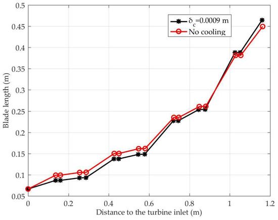
Figure 7.
Geometry comparison with and without cooling.
Under the condition of constant temperature at the turbine inlet, increasing the TBC thickness reduces the amount of cooling air needed, and then, changes the gas mass flow rate at the turbine inlet, so that the structure of the turbine flow passage changes accordingly. However, the question of how to quantitatively analyze the series of impacts is still a problem that needs to be solved. In this section, the model established and validated above was used to quantitatively analyze the impact of changing the TBC thickness on the cooling air flow, turbine inlet mass flow rate, and turbine flow passage geometry.
Figure 8 shows the changes in the cooling air ratio in relation to TBC thickness. When the TBC thickness was 0.5 mm, the cooling air ratio was about 16.5%, which is consistent with the cooling air ratio of an F-class gas turbine. With increases in the TBC thickness, the cooling air ratio decreased gradually. When the thickness was 1.3 mm, the cooling air ratio decreased to 10.0%. This value is lower than that of a general F-stage gas turbine, because, we assume, the TBCs are also applied to the blades in addition to the first-stage stationary blades—which makes the required cooling air mass flow rate lower. These results also prove that the application of TBCs can reduce the demand for cooling air. Equation (19) is obtained by polynomial fitting, where is the cooling air ratio. The correlation coefficient R2 is 0.9975.
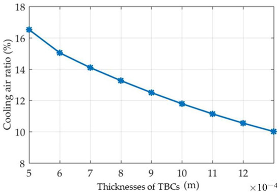
Figure 8.
The relationship between the cooling air ratio and TBC thickness.
Figure 9 shows the change rule of the gas flow rate at the turbine inlet in relation to TBC thickness, which is opposite to the change rule of the cooling air ratio. When the TBC thickness was 0.5 mm, the turbine inlet flow was 586.90 kg/s. With increases in the thicknesses, the turbine inlet flow increased gradually. When the thickness was 1.3mm, the turbine inlet flow increased to 632.62 kg/s. The result of the polynomial fitting is shown in Equation (20), where is the mass flow rate of the turbine inlet. The correlation coefficient R2 is 0.9975.

Figure 9.
The relationship between the turbine inlet mass flow rate and TBC thickness.
Figure 10 shows the structure of the turbine flow passage corresponding to different TBC thicknesses and without cooling air conditions. It can be seen that with increases in the TBC thickness, the structure of the turbine flow passage was closer to that found without consideration of the cooling air. The reason for this is that as the TBC thickness increases, the cooling air flow decreases, and the impact of the cooling air on the structure of the turbine flow passage gradually decreases. Cases where cooling air is not considered can be considered as cases where the TBCs are thick enough that cooling air is not required. In fact, the TBC thickness cannot be very large because of the cost and the limitations of geometric space. The expanding angle can be taken as a parameter to quantitatively characterize this effect. Figure 11 shows the variation rule of the turbine expanding angle in relation to TBC thickness. When the TBC thickness was 0.5 mm, the turbine expanding angle was about 19.87 degrees. With increases in the thickness, the turbine expanding angle decreased gradually. When the thickness was 1.3 mm, the turbine expanding angle decreased to 18.67 degrees. Equation (21) is obtained by polynomial fitting, where is the turbine expanding angle. The correlation coefficient R2 is 0.9966.
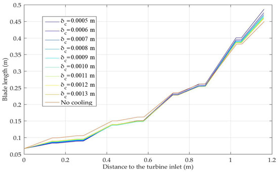
Figure 10.
Structure of the turbine flow passage.
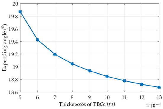
Figure 11.
The relationship between the cooling air ratio and TBC thickness.
5. Conclusions
This paper developed a model for turbine flow passage considering the impacts of cooling air and TBCs based on the calculation of aerothermodynamics, which is closer to actual gas turbines than previous models. To calculate the mass flow rate of the cooling air, the heat transfer process in the turbine was considered based on a series of hypotheses. The heat transfer processes in turbines mainly consist of convection heat transfer between the high-temperature gas flow and the blades’ outer surfaces, radiation between the high-temperature gas flow and the blades’ outer surfaces, convection heat transfer between the cooling air flow and the blades’ inner surfaces, radiation between the turbine cylinder and the blades’ outer surfaces, and heat conducted inside the blade.
The proposed model has the function of analyzing the impact of TBCs on the turbine’s geometry, and is proved to have relative errors that are all within a margin of error of 10% across the thickness range analyzed. We used this model to quantitatively analyze the impact of TBC thickness on turbine flow passage. The variation rules of the cooling air ratio, turbine inlet mass flow rate, and turbine flow passage structure within the range of 0.0005 m to 0.0013 m of TBC thicknesses are given. There are obvious impacts of TBC thickness on the blades’ lengths and the turbine expanding angle according to this analysis. It is necessary to take these impacts into account in turbine designs.
Different from existing studies that mainly focus on the materials and mechanisms of TBCs and the impact of TBCs on turbine blades, this paper proposes a method for turbine flow passage design that takes the heat transfer of TBC-assisted cooling into account in the aerothermodynamics calculations. It focuses on the impacts of TBCs on the overall turbine. Analyzing these impacts from a novel perspective, this work provides a foundation for further turbine model development with consideration to cooling with TBCs.
Author Contributions
Formal analysis, investigation, methodology, software, validation, writing—original draft, Y.Z.; supervision, visualization, writing—review and editing, P.L. and Z.L. All authors have read and agreed to the published version of the manuscript.
Funding
This research was funded by the National Science and Technology Major Project of China, grant number 2017-I-0002-0002.
Institutional Review Board Statement
Not applicable.
Informed Consent Statement
Not applicable.
Data Availability Statement
Not applicable.
Conflicts of Interest
The authors declare no conflict of interest.
References
- Hada, S.; Takata, K.; Iwasaki, Y.; Yuri, M.; Masada, J. High-Efficiency gas turbine development applying 1600 °C class “J” technology. Mitsubishi Heavy Ind. Tech. Rev. 2015, 52, 2–9. [Google Scholar]
- El-Masri, M.A. On thermodynamics of gas-turbine cycles: Part 1—Second law analysis of combined cycles. J. Eng. Gas Turbines Power 1985, 107, 880–889. [Google Scholar] [CrossRef]
- El-Masri, M.A. On thermodynamics of gas-turbine cycles: Part 2—A model for expansion in cooled turbines. J. Eng. Gas Turbines Power 1986, 108, 151–159. [Google Scholar] [CrossRef]
- El-Masri, M.A. On thermodynamics of gas-turbine cycles: Part 3—Thermodynamic potential and limitations of cooled reheat-gas-turbine combined cycles. J. Eng. Gas Turbines Power 1986, 108, 160–168. [Google Scholar] [CrossRef]
- Young, J.B.; Wilcock, R.C. Modeling the air-cooled gas turbine: Part 1—General thermodynamics. J. Turbomach. 2002, 124, 207–213. [Google Scholar] [CrossRef]
- Young, J.B.; Wilcock, R.C. Modeling the air-cooled gas turbine: Part 2—Coolant flows and losses. J. Turbomach. 2002, 124, 214–221. [Google Scholar] [CrossRef]
- Walsh, P.P.; Fletcher, P. Gas Turbine Performance; Blackwell Science Ltd.: Oxford, UK, 1998. [Google Scholar]
- Chiesa, P.; Macchi, E. A thermodynamic analysis of different options to break 60% electric efficiency in combined cycle power plants. J. Eng. Gas Turbines Power 2004, 126, 770–785. [Google Scholar] [CrossRef]
- Brown, A.; Jubran, B.A.; Martin, B.M. Coolant optimization of a gas turbine engine. Proc. Inst. Mech. Eng. Part A J. Power Energy 1993, 207, 31–47. [Google Scholar] [CrossRef]
- Moon, S.W.; Kwon, H.M.; Kim, T.S.; Do, W.K. A novel coolant cooling method for enhancing the performance of the gas turbine combined cycle. Energy 2018, 160, 625–634. [Google Scholar] [CrossRef]
- Sahu, M.K. Thermo-Economic investigation of power utilities: Intercooled recuperated gas turbine cycle featuring cooled turbine blades. Energy 2017, 138, 490–499. [Google Scholar] [CrossRef]
- Salpingidou, C.; Tsakmakidou, D.; Vlahostergios, Z.; Misirlis, D.; Flouros, M.; Yakinthos, K. Analysis of turbine blade cooling effect on recuperative gas turbines cycles performance. Energy 2018, 164, 1271–1285. [Google Scholar] [CrossRef]
- Okajima, Y.; Kudo, D.; Okaya, N.; Torigoe, T.; Kaneko, H.; Mega, M.; Ito, E.; Masada, J.; Tsukagoshi, K. Evolution of thermal barrier coatings for land based gas turbines at MHI. Therm. Spray Technol. 2014, 6, 56–62. [Google Scholar]
- Ogiriki, E.A.; Li, Y.G.; Nikolaidis, T.; Isaiah, T.E.; Sule, G. Effect of fouling, thermal barrier coating degradation and film cooling holes blockage on gas turbine engine creep life. Procedia CIRP 2015, 38, 228–233. [Google Scholar] [CrossRef] [Green Version]
- Sahith, M.S.; Giridhara, G.; Kumar, R.S. Development and analysis of thermal barrier coating on gas turbine blades—A review. Mater. Today Proc. 2018, 5, 2746–2751. [Google Scholar] [CrossRef]
- Wu, S.; Zhao, Y.; Li, W.; Liu, W.; Wu, Y.; Liu, F. Research progresses on ceramic materials of thermal barrier coatings on gas turbine. Coatings 2021, 11, 79. [Google Scholar] [CrossRef]
- Gurrappa, I.; Sambasiva Rao, A. Thermal barrier coatings for enhanced efficiency of gas turbine engines. Surf. Coat. Technol. 2006, 201, 3016–3029. [Google Scholar] [CrossRef]
- Ziaei-Asl, A.; Ramezanlou, M.T. Thermo-Mechanical behavior of gas turbine blade equipped with cooling ducts and protective coating with different thicknesses. Int. J. Mech. Sci. 2019, 150, 656–664. [Google Scholar] [CrossRef]
- Sankar, V.; Ramkumar, P.B.; Sebastian, D.; Joseph, D.; Jose, J.; Kurian, A. Optimized thermal barrier coating for gas turbine blades. Mater. Today Proc. 2019, 11, 912–919. [Google Scholar] [CrossRef]
- Nagabandi, K.; Pujari, A.K.; Iyer, D.S. Thermo-Mechanical assessment of gas turbine combustor tile using locally varying thermal barrier coating thickness. Appl. Therm. Eng. 2020, 179, 115657. [Google Scholar] [CrossRef]
- Huang, X.; Pu, J.; Wang, J.H.; Qu, Y.-F.; He, J.-H. Sensitivity analysis of internal layout and coating thickness to overall cooling performances of laminated cooling configurations with surface thermal barrier coatings. Appl. Therm. Eng. 2020, 181, 116020. [Google Scholar] [CrossRef]
- Frackowiak, A.; Olejnik, A.; Wróblewska, A.; Cialkowski, M. Application of the protective coating for blade’s thermal protection. Energies 2021, 14, 50. [Google Scholar] [CrossRef]
- Radhakrishnan, K.; Park, J.S. Thermal analysis and creep lifetime prediction based on the effectiveness of thermal barrier coating on a gas turbine combustor liner using coupled CFD and FEM simulation. Energies 2021, 14, 3817. [Google Scholar] [CrossRef]
- Yunus, S.M.; Mahalingam, S.; Manap, A.; Afandi, N.M.; Satgunam, M. Test-Rig simulation on hybrid thermal barrier coating air system for advanced gas turbine under prolonged exposures—A review. Coatings 2021, 11, 560. [Google Scholar] [CrossRef]
- Zhu, J.; Hu, C.S.; You, G.W.; Zhou, X.H.; Chen, Z.J.; Qin, H. Calculation of the effect of thermal barrier coatings of vanes. J. Petrochem. Univ. 2003, 16, 44–47. (In Chinese) [Google Scholar]
- Zhong, Y.H. Study on Thermal Barrier Coating of Gas Turbine Blade. Ph.D. Thesis, Mechanical Science Research Institute, Beijing, China, 2015. (In Chinese). [Google Scholar]
- Zhu, H.R.; Zhang, L.; Guo, T.; Liu, C.L. Heat Transfer and Cooling of High Temperature Turbine Blades; Xi’an Jiaotong University Press: Xi’an, China, 2017. (In Chinese) [Google Scholar]
- Shu, S.Z.; Zhu, L.; Ke, X.L.; Jiang, Z.K. Turbomachinery Theory; Tsinghua University Press: Beijing, China, 1991. (In Chinese) [Google Scholar]
Publisher’s Note: MDPI stays neutral with regard to jurisdictional claims in published maps and institutional affiliations. |
© 2021 by the authors. Licensee MDPI, Basel, Switzerland. This article is an open access article distributed under the terms and conditions of the Creative Commons Attribution (CC BY) license (https://creativecommons.org/licenses/by/4.0/).