1. Introduction
As the world looks beyond oil and gas as principal energy sources, different renewable resources offer partial solutions. An important consideration in assessing viability is whether the infrastructure associated with oil and gas exploitation can be repurposed. This question does not have a single answer as different reservoirs and resources have quite different well types and different geological settings. Here we focus specifically on repurposing of unconventional gas wells, common in Northeastern British Columbia (BC), Canada, for the purpose of geothermal energy. The basic value proposition is as follows. The gain is that a deep and long well already exists, reducing the significant capital cost of construction. The trade-off is that the geological conditions may be non-ideal for geothermal energy extraction and the location of the wells is predetermined. We discuss other BC specifics and considerations below, mainly as an illustration of the complexities of such decisions. The main thrust of the paper is however technical: namely to estimate power output from such a well under intermittent operation over many years.
Geothermal energy can be classified by different parameters. Generally, the temperature of the earth’s crust varies between 5 and 360 °C. Based on the soil or ground temperature, geothermal energy can be categorized as follows [
1]:
Low temperature: Tsoil < 90 °C
Moderate temperature: 90 °C < Tsoil < 150 °C
High temperature: 150 °C < Tsoil
Mainly, moderate and some low temperature geothermal energy is used for space heating and cooling, especially when the ground temperature is lower than 110 °C. In general, in order to extract the heat of the rock, pipes with different configurations are placed into boreholes. The borehole depth can be 200 m for low temperature geothermal systems while it can reach 4000 m in deep BHEs, which are used for moderate temperature geothermal systems [
1,
2,
3,
4,
5].
There are a lot of studies that have investigated the thermal performance of deep BHEs [
6,
7,
8,
9,
10]. For example, Li et al. [
11] developed a transient computational model based on finite difference methods that was capable of considering the effect of ground stratification on the thermal performance of a deep BHE. They verified their proposed model with experimental results, and then studied the effect of different parameters including the pipe diameter and flow rate. Their results showed that increasing the buried pipe diameter and flow rate increases the heat extraction rate. Moreover, they found that the ground temperature will be disturbed up to radius of 7 m during the heating period. Zhang et al. [
12] studied the thermal performance of a U-shape BHE which consists of two vertical BHE and one horizontal BHE. For this goal, they developed a mathematical model based on the finite difference method. Afterwards, they studied the effect of two parameters viz undisturbed ground temperature and BHE’s flow rate, on the thermal performance of BHE. They found that by doubling the flow rate of 60
, the heat extraction is increased from 1100 to 1190 kW. Hu et al. [
13] investigated the effect of using temperature-dependent property variations in the numerical model on the thermal performance of deep BHE. Their results demonstrated that extracting the ground heat causes the mean convective heat transfer coefficient of the working fluid to be reduced while it increases the thermal diffusivity of rock around the BHE. Moreover, they showed that the variation of material properties led to an over-prediction of heat extraction rate. In another study, Jia et al. [
14] developed a semi-analytical model by utilizing an adjustable multi-layer model to study the effect of geothermal gradient, ground water seepage, and insulation length on the thermal performance of a vertical and horizontal BHE with a depth of 2505 m. Their results demonstrated that ground water seepage and insulation length have a positive effect on the performance of BHEs.
In practical applications, deep BHEs mainly have intermittent operation instead of continuous operation because after the heating season, their operation is stopped, so it is necessary to study the thermal performance of deep BHEs in intermittent operation. There are several research papers that have studied the short-term performance of BHEs in intermittent mode [
15,
16,
17,
18,
19,
20]. For example, Sofyan et al. [
21] compared the short-term performance of BHE in continuous mode and intermittent mode. They considered that working period and recovery period is 8 h and 16 h, respectively. By examining the outlet temperature, they found that the heat extraction rate of BHE in intermittent mode is significantly higher than that in continuous mode. In another study, Yuan et al. [
22] studied the effect of recovery period ratio on the short-term performance of BHE in intermittent mode by considering three different recovery period ratios including 1/3, 1/2, and 2/3. According to their results, by increasing the recovery period ratio, the heat extraction rate is increased significantly. For example, when the recovery period ratio increases from 1/3 to 2/3, the heat extraction rate is increased about 30%.
There are limited numbers of research papers that have studied the long-term performance of BHE in intermittent operation [
23,
24,
25,
26]. For example, Cai et al. [
27] evaluated and compared the ten-year thermal performance of deep BHE in continuous mode and intermittent mode in which the working and recovery period is 4 months and 8 months respectively. They also study the effect of recovery period ratio on the thermal performance of deep BHE by considering four recovery period ratios including 0, 1/3, 1/2, and 2/3. Their results showed that increasing the recovery period ratio increases the outlet fluid temperature of deep BHE. By increasing the recovery period ratio from 0 to 2/3, the outlet fluid temperature increases from 31.5 °C to 37.5 °C, but the total heat extraction energy is decreased from 850 MWh to 480 MWh. In another study, Zhao et al. [
28] developed a model for fast calculation of the recovery process in the intermittent operation of deep BHEs. Their proposed model could predict the heat extraction of deep BHE in intermittent mode with about 10 percent error.
Based on the literature, there is no study that has explored the long-term performance of deep horizontal BHEs in intermittent mode comprehensively. Moreover, there are several specific parameters such as periodic time interval and flow rate ratio that have not been studied yet. Thus, the main goal of this paper is to conduct such a comprehensive study. In this regard, we develop an analytical mode to predict thermal performance of BHEs and verify the model using experimental results. We then investigate the effect of various parameters including flow rate of circulating fluid, undisturbed ground temperature, inlet fluid temperature, periodic time interval, flow rate ratio, recovery period ratio, and ground thermal conductivity. Our interest is in the long-term performance of deep horizontal BHE in intermittent modes.
While the technical novelty of our study is described above, the other aspect of the paper is as a case study for feasibility for such repurposing of oil and gas wells. The value proposition is laid out in the first paragraph of the paper. Unfortunately, not all oil and gas wells are alike, in terms of depth, horizontal reach or geothermal potential: their original purpose was hydrocarbon extraction. Thus, any such study must focus on typical wells from particular fields or regions. Equally, geothermal power has its own constraints, which means that one must also assess the potential usages of the power in any particular region.
1.1. Specifics of the BC Setting
Although dwarfed by its Eastern neighbor, BC has been a significant oil and gas for many years and has an industry dating back over 100 years. The main regions are in the Northeast of the province. Since the early 2000s there has been strong development of the Montney formation (which bridges also into Alberta) and lesser development of the Horn River and Liard basins further North. These reserves are shale gas and tight oil, accessed only recently via the methods of directional drilling and hydraulic fracturing. Of the over 25,000 wells in BC, more than 14,000 have been drilled since 2000. Cumulative production from the Montney surpassed 4.3 trillion cubic feet in December 2015 [
29] and this is one of the largest shale gas resources in North America.
The wells of BC are reviewed recently in [
30]. A typical recent horizontal well has mean measured depth of 3443 m and true vertical depth of 1670 m, meaning a horizontal extent of around 1800 m. The trend is towards longer wells, extending up to nearly 6000 m in length. The wells are often pad-drilled, meaning that the well heads are grouped in close proximity at surface, drilled at the same time, with the laterals extending to access different parts of the reservoir. As well as cost savings, pad drilling has vastly reduced the % of dry holes and carries evident benefits for later geothermal exploitation. The thermal gradients in the area are classified as moderate (<54 K/km) and reservoir temperatures vary (60–110 °C, Montney; 80–160 °C, Horn River; 150–180 °C, Liard); see [
31]. These are moderate numbers. Thus, the focus for geothermal energy in BC has generally been in coastal areas to the West, where more conventional geothermal power may be feasible, e.g., [
32].
In [
30] the average lifetime of horizontal wells surveyed is 9.6 years, compared to 12.1 and 18.3 years for deviated and vertical wells, respectively. Thus, decisions on abandonment of wells and/or alternative futures are timely. While unlikely to be a major power contributor, as a resource for local communities we feel geothermal repurposing has merit. The vast area comprising Peace River and Fort St John districts is sparsely populated (<65,000 persons), with the communities centred around jobs in the energy industry, agriculture, local government, and also indigenous communities. Indeed, indigenous communities are leading the way in transitioning to geothermal energy [
33].
The Peace River is the largest agricultural area in BC. The Northern climate with short Summers of long days favours specific agricultural activities and crops, (wheat, oats, barley, canola, cattle, dairy, vegetables, etc.). The effects of climate change deliver projections of +5 to +14 frost free days in the 2020s rising to +10 to +25 days in the 2050s [
34], likely to increase the importance of the region as an agricultural centre. Availability of cheap background heating (as studied here) could support greenhouse agriculture or other winter growing, as well as serving small agricultural communities close to depleted wells.
There is a recent development of the site C dam on the Peace River, with a projected 5100 GWh of hydroelectric power generated annually. This adds to the local energy landscape. The combination of cooler Northern temperatures and cheap local power may make the area attractive also to high-tech installations such as server farms, which may also exploit geothermally repurposed energy for background winter heating.
Finally, there may be both technological and regulatory/environmental advantages to repurposing of wells. Before a hydraulically fractured well can repurposed, completion work is necessary on the surrounding depleted reservoir. Potentially the fractured rock can be injected with thermally advantageous materials (e.g., high conductivity) before being sealed with cement, prior to installing a BHE in the horizontal section, i.e., the fractures may eventually help deliver better performance. In [
30] high leakage rates are reported for recent wells. Although all leaks should be fixed prior to well abandonment, regulations require little post-abandonment inspection. One may question whether it is better to have an active geothermal plant at which leakage will be monitored over the lifetime, compared to a remote abandoned site.
3. Results
In this section, the results of our study are presented. The effect of several pivotal parameters including flow rate, rock reservoir temperature, inlet water temperature, and ground thermal conductivity on the thermal performance of deep horizontal BHEs in continuous and intermittent modes is scrutinized. Moreover, there are some parameters that are specific for intermittent operation which are periodic time interval, flow rate ratio, and recovery period ratio that are defined in
Table 6.
In this study, a base case is considered to have the parameters that are listed in
Table 7. It should be noted that when a particular parameter is investigated, all other parameters remain the same as the base case.
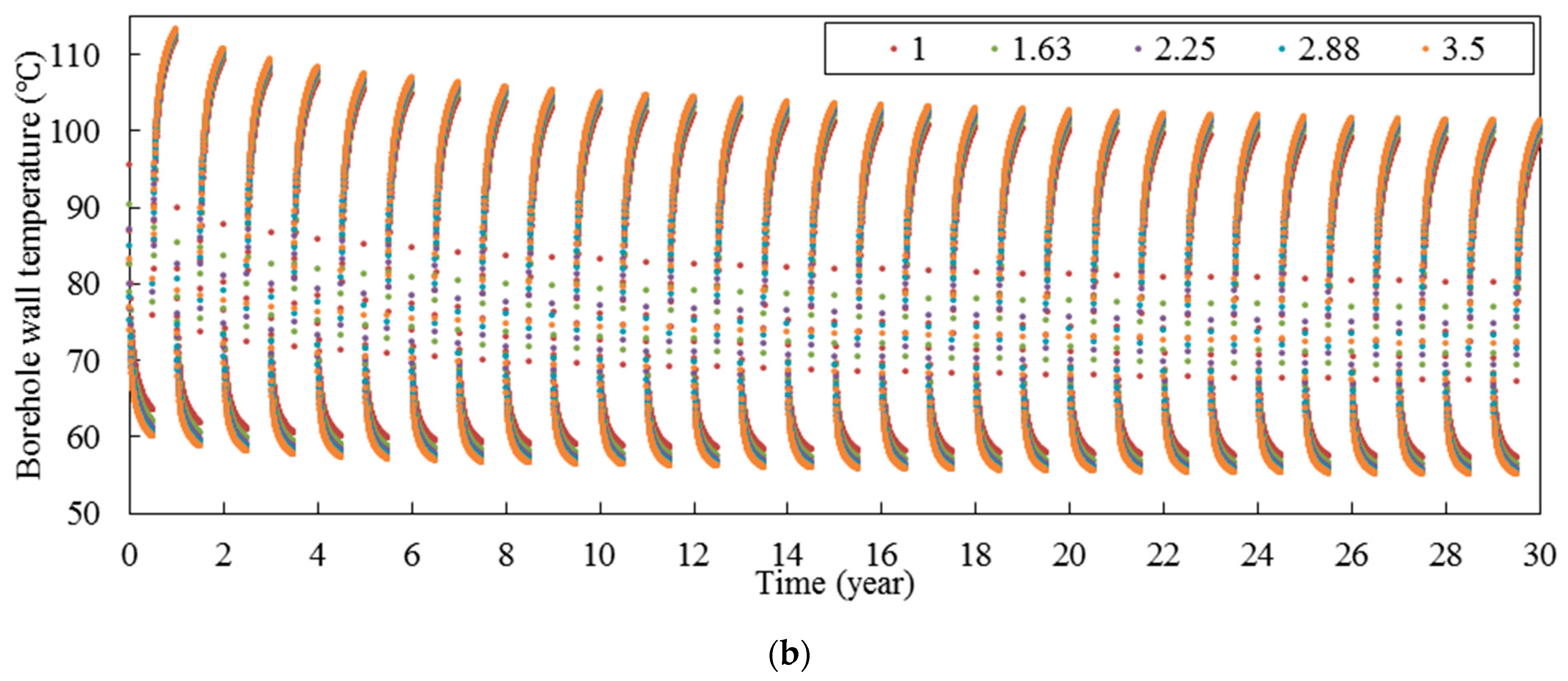
The long-term thermal performance of a deep horizontal borehole heat exchanger for the base case is presented in
Figure 4. According to
Figure 4a, due to the intermittent operation, at the beginning of each year, the heat extraction rate in intermittent operation is significantly greater than that in continuous mode. For example, the heat exchange rate at the beginning and middle of the year 30th in intermittent mode is 2.01 and 1.17 times higher than those in continuous mode. Moreover, the difference between the continuous and intermittent mode increases by passing the time. According to
Figure 4b, the borehole wall temperature in intermittent operation is noticeable higher than that in continuous mode. The average borehole wall temperature during the 30 years in continuous mode is 53.6 °C while it is 78.5 °C in intermittent mode. Moreover, the borehole wall temperature at beginning, middle and end on the 30th year in intermittent mode is 73.91 °C, 55.55 °C, and 100.73 °C, respectively, and all of them in continuous mode are about 51.8. The maximum temperature that the borehole wall can reach at the end of each year is decreased by passing time. For example, the borehole wall temperature at the end of the first year in intermittent mode is 113.00 °C while it is 100.73 °C at the end of the 30th year.
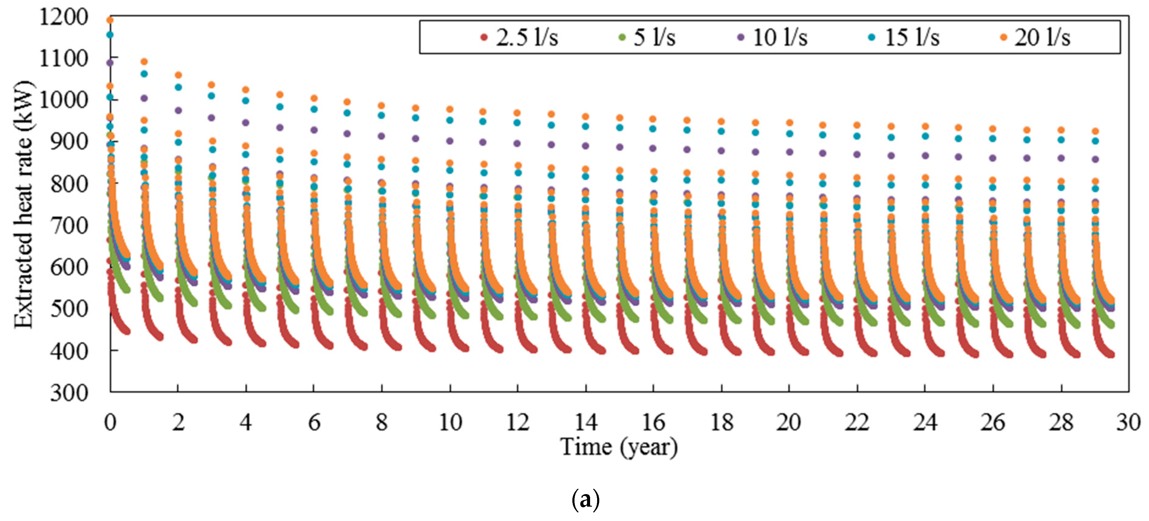
3.1. Flow Rate
Inlet flow rate plays a key role in determining the thermal performance of BHE. In this section the effect of flow rate on the thermal performance of horizontal BHE is investigated. It should be noted that all the parameters in this section are the same with base case (
Table 7) except the temperature difference between inlet and outlet fluid as it depends on the inlet flow rate.
Figure 5 shows the long-term thermal performance of deep horizontal BHE in continuous mode for five different flow rates including 2.5, 5, 10, 15, and 20 L/s. According to
Figure 5a, by increasing the flow rate, the heat extraction rate is improved. This can be attributed to the fact that by increasing the flow rate, according to the
Figure 5b, the outlet fluid temperature (or the average of fluid temperature in BHE) is decreases, so the temperature difference between fluid and rock reservoir increases, so the heat exchange rate is improved. Furthermore, it can be seen that by increasing the flow rate, the increment of heat extraction rate is reduced. According to
Figure 5d, it can be seen that by increasing the flow rate, the temperature difference between inlet and outlet fluid of BHE is decreased.
In order to study the effect better, the heat extraction rate and temperature difference between inlet and outlet fluid at the year 30th in continuous mode for different flow rates are plotted in
Figure 6. According to this figure, when the flow rate of 2.5 L/s is doubled, the heat extraction rate is improved 16.2%, and the temperature difference between inlet and outlet fluid is reduced 41.9%. However, when the flow rate of 10 L/s is doubled, the heat extraction rate increases only 1.1% and the temperature difference between inlet and outlet fluid is decreased 24.2%. Generally, in practical application, the temperature difference between inlet and outlet fluid is around 10 °C [
1]. In this study, in order to have a fair comparison between different cases, the flow rate in the continuous mode is determined by setting the temperature difference between inlet and outlet fluid to 10 °C at the end of the 30th year. In this regard, the flow rate of base case is 10.1 L/s. For the base case, Re number is about 6.4 × 10
4, so the flow is turbulent, and the calculated coefficient of convection (h
c) is about 3.0 × 10
3 W m
−2·K
−1.
Figure 7 shows the heat extraction rate and borehole wall temperature in intermittent mode for different flow rates. According to
Figure 7a, in the intermittent mode, a similar trend to that in continuous mode can be observed, so by increasing the flow rate, the heat extraction rate is increased, but the increment of heat extraction rate is reduced. Moreover, by increasing the flow rate, the variation of the heat extraction rate in each year is increased. For example, in the 30th year, when the flow rate is 2.5 L/s, the variation of heat extraction rate is 168.6 kW, but when the flow rate is 20 L/s, the variation is 405.9 kW. According to
Figure 7b, when the system is in the working period in each year, there is a significant difference between borehole wall temperatures of different flow rates, but when the system is in the recovery period, the difference between borehole wall temperatures of different flow rates is much smaller. However, at long times, the difference between borehole wall temperatures is increased (compare regions I and II in
Figure 7b).
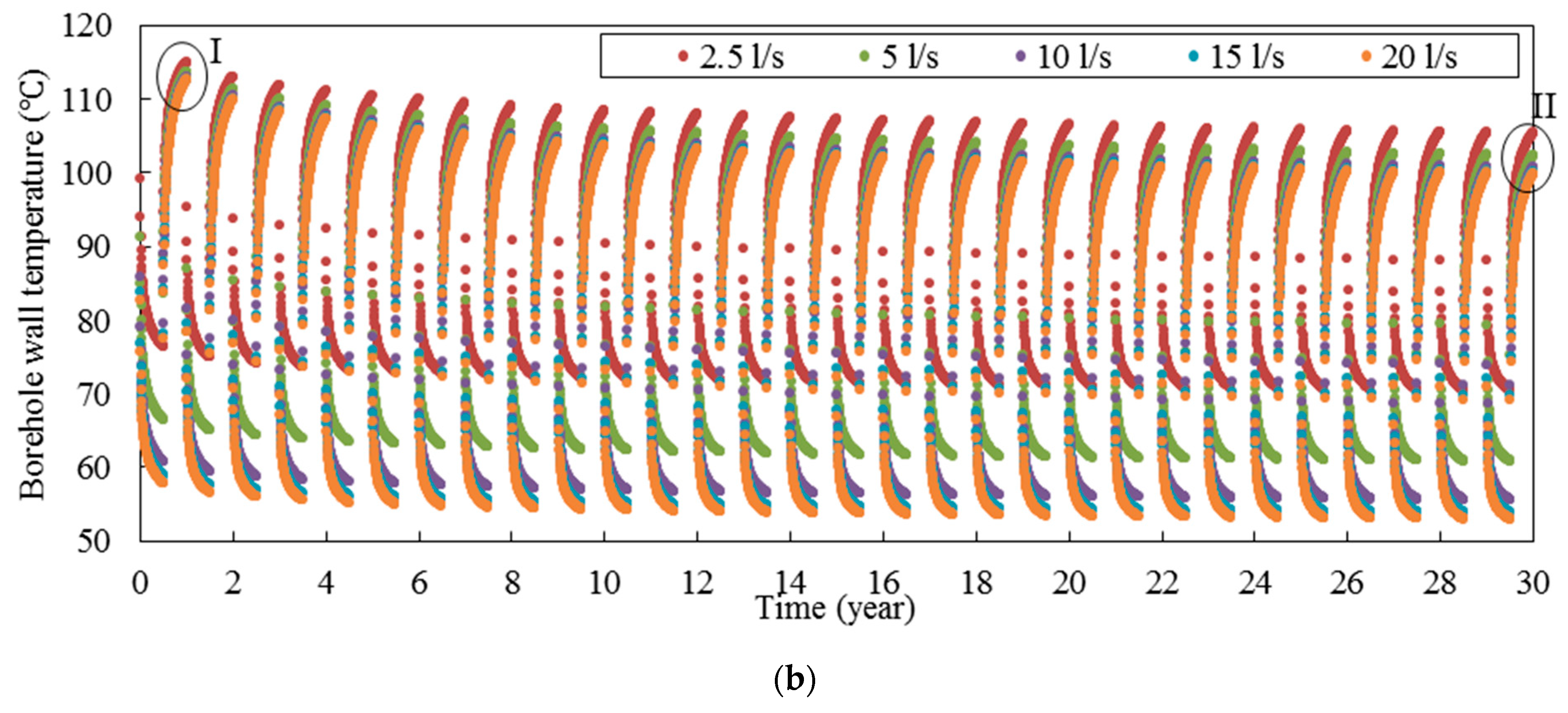
3.2. Undisturbed Ground Temperature
Undisturbed ground temperature is one of the important parameters that determine the thermal performance of deep BHEs. In this section, the effect of this parameter on the long-term performance of BHE by considering five different undisturbed ground temperatures: 80, 90, 100, 110, and 120 °C are examined. All other parameters are the same as the base case (
Table 7).
Figure 8 shows the long-term performance of deep horizontal BHE in continuous mode for five different ground temperatures. According to this figure, by increasing the undisturbed ground temperature, the heat extraction rate increases significantly. For example, when ground temperature increases from 80 °C to 120 °C, the heat extraction rate at the end of the 30th year increases from 221.3 to 424.9 kW and borehole wall temperature at the end of the 30th year increases from 44.5 °C to 51.8 °C.
Figure 9 shows the long-term performance of deep horizontal BHE in intermittent mode for five different ground temperatures. According to
Figure 9a, the effect of undisturbed ground temperature on the heat extraction rate in intermittent mode is similar to that in continuous mode, so by increasing the undisturbed ground temperature, the heat extraction is increased noticeably. Moreover, when undisturbed ground temperature is increased, the variation of heat extraction rate is also increased. For example, the variation of heat extraction rate in the 30th year is 157.7, 207.5, 257.4, 308.1, and 358.7 kW when the undisturbed ground temperature is 80, 90, 100, 110, and 120 °C, respectively.
The borehole wall temperature also decreases when the undisturbed ground temperature is decreased, as might be expected. Moreover, the borehole wall temperature when the system is in the working period is not very sensitive to the ground temperature. For example, when the undisturbed ground temperature decreases from 120 to 80 °C, the borehole wall temperature at the middle of 30th year only decreases from 55.5 to 46.8 °C. On the other hand, when the system is in the recovery period, the variation of borehole wall temperature increases significantly. For example, when the undisturbed ground temperature is increased from 80 to 120 °C, the borehole wall temperature at the end of the 30th year is increased from 70.1 to 100.7 °C.
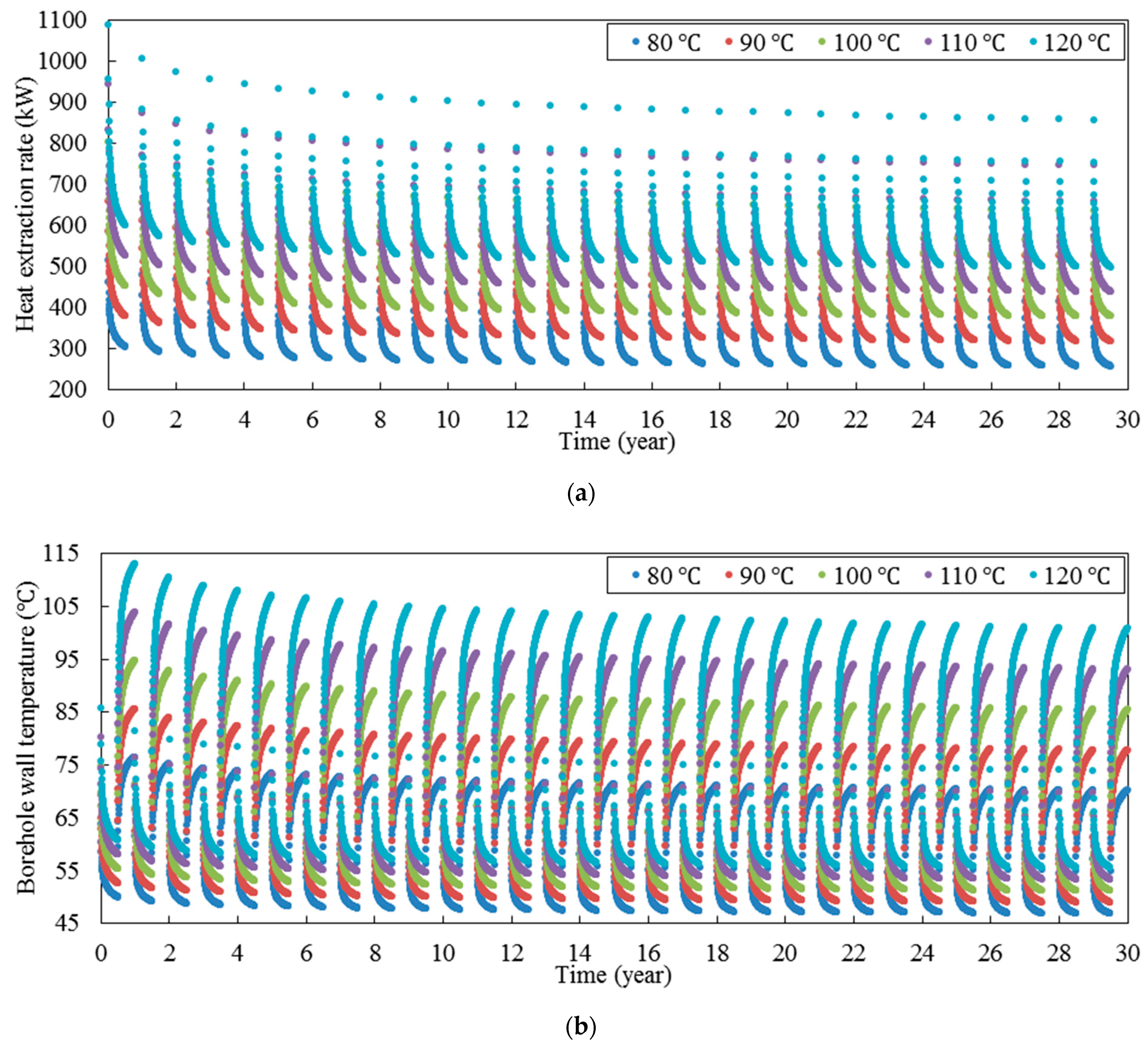
3.3. Inlet Fluid Temperature
Inlet fluid temperature of BHEs depends on their application. Usually, deep BHEs are used directly for space heating and producing hot water or indirectly for space heating in which they are connected to the heat pumps. Therefore, we study a range of inlet water temperature: 10 to 90 °C. All other parameters are the same as the base case (
Table 7).
Figure 10 shows the long-term performance of deep horizontal BHE in continuous mode for different inlet water temperatures including 10, 30, 50, 70, and 90 °C. According to
Figure 10a, by increasing the inlet fluid temperature, the heat extraction rate decreases significantly. For example, when the inlet fluid temperature increases from 10 to 90 °C, the heat extraction rate decreases from 526 to 117 kW. According to
Figure 10b, the borehole wall temperature is completely dependent on the inlet fluid temperature. Moreover, by decreasing the inlet fluid temperature, the borehole wall temperature needs more time to reach a quasi-steady state condition.
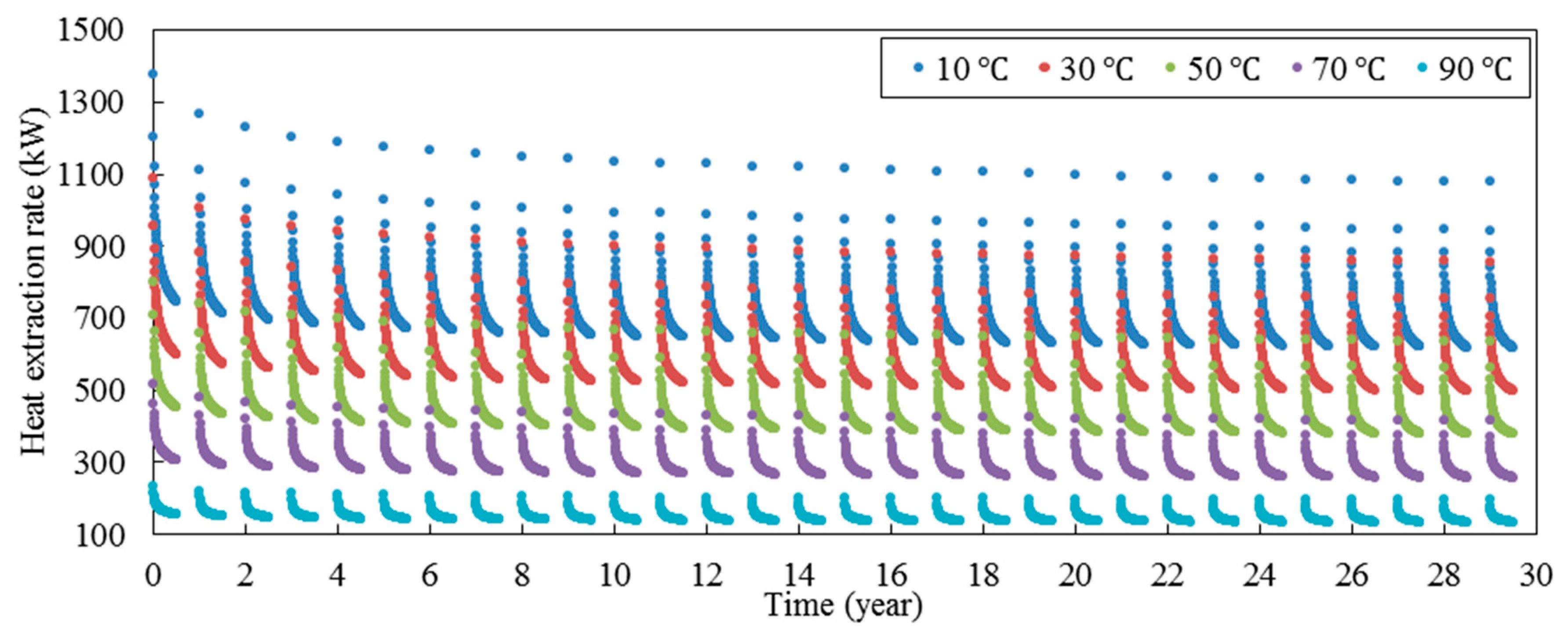
Figure 11 shows the heat extraction rate over time in the intermittent mode for different inlet fluid temperatures. As it can be seen, similar to the continuous mode, by increasing the inlet fluid temperature, the heat extraction rate is decreased. Moreover, by increasing the inlet fluid temperature, the variation of heat extraction rate in a year decreases significantly. For example, the variation of heat extraction rate in the 30th year is 62, 158, 259, 359, and 460 kW when the inlet fluid temperature is 90, 70, 50, 30, and 10 °C respectively; therefore, it shows that by increasing the inlet fluid temperature, the thermal performance of BHE reach a quasi-steady state condition sooner.
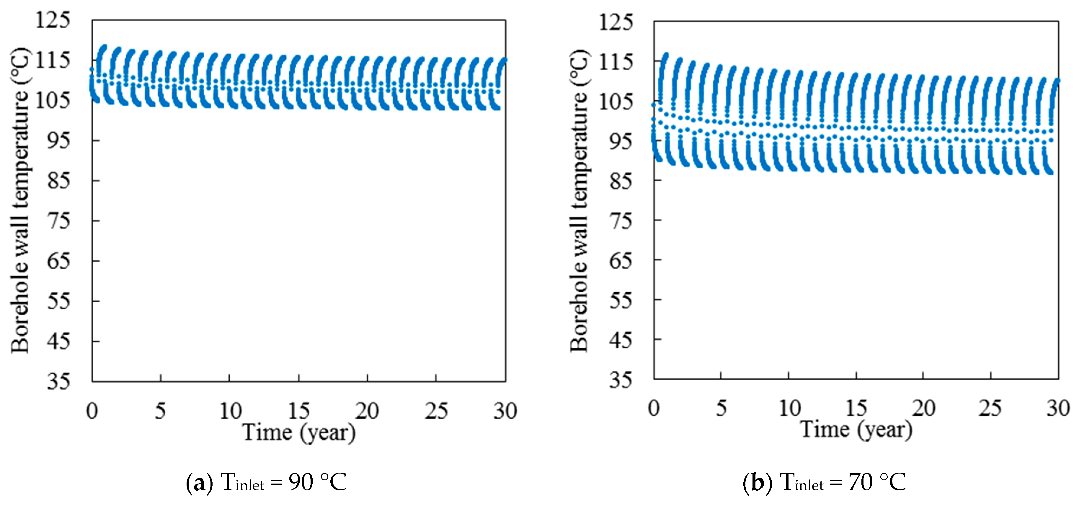
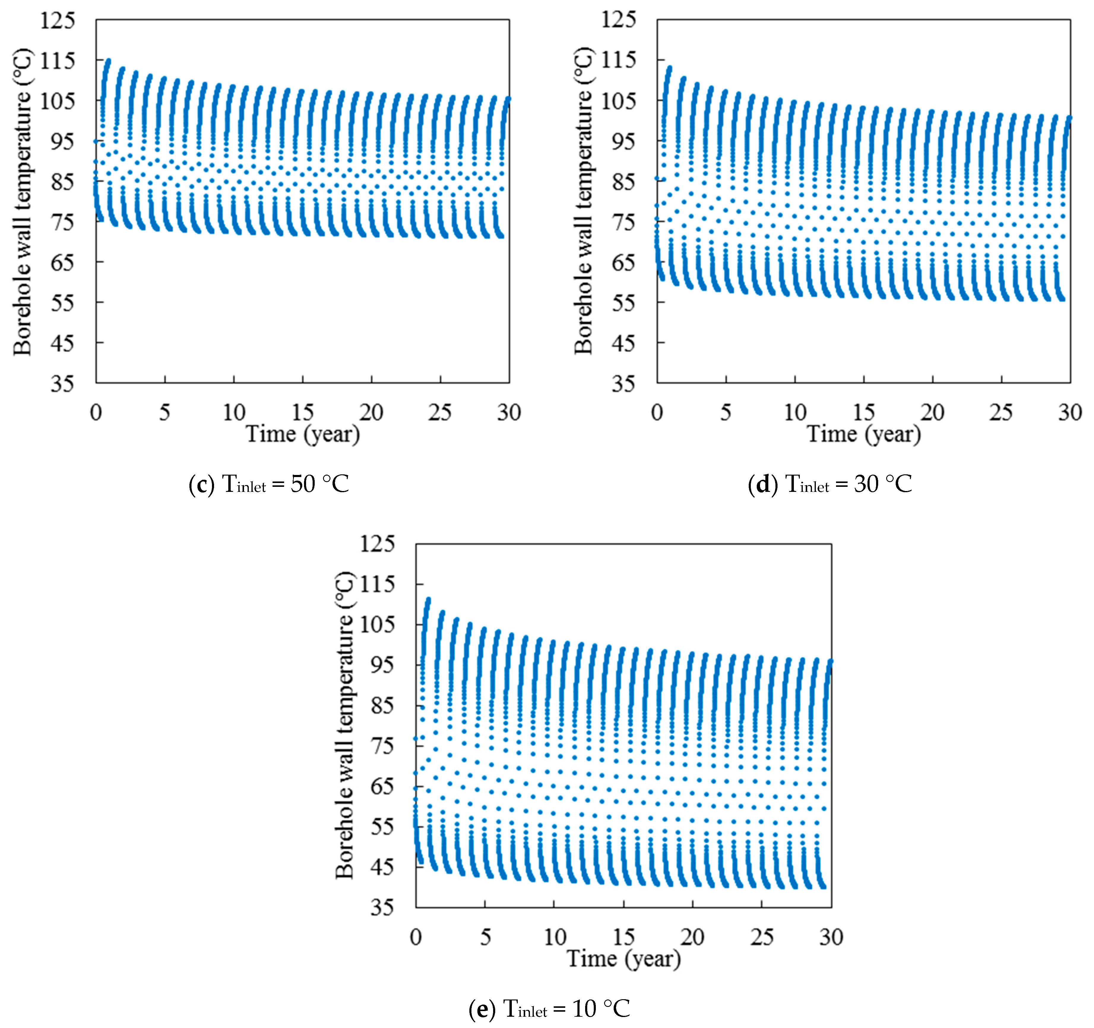
Figure 12 shows the borehole wall temperature over the time for five different inlet fluid temperatures. As can be seen, by increasing the inlet fluid temperature, the borehole wall temperature increases significantly. For example, the borehole wall temperature middle of 30th years is 40, 56, 71, 87, and 103 °C, when the inlet fluid temperature is 90, 70, 50, 30, and 10 °C, respectively. Moreover, the variation of borehole wall temperature in each year is increased when the inlet fluid temperature decreases. For example, the difference between maximum and minimum borehole wall temperature in the period of 30 years is 71, 57, 44, 29, and 15 °C, when the inlet fluid temperature is 90, 70, 50, 30, and 10 °C, respectively. Furthermore, it can be seen that the variation of borehole wall temperature when the system is in working period is smaller than that when the system is in recovery period.
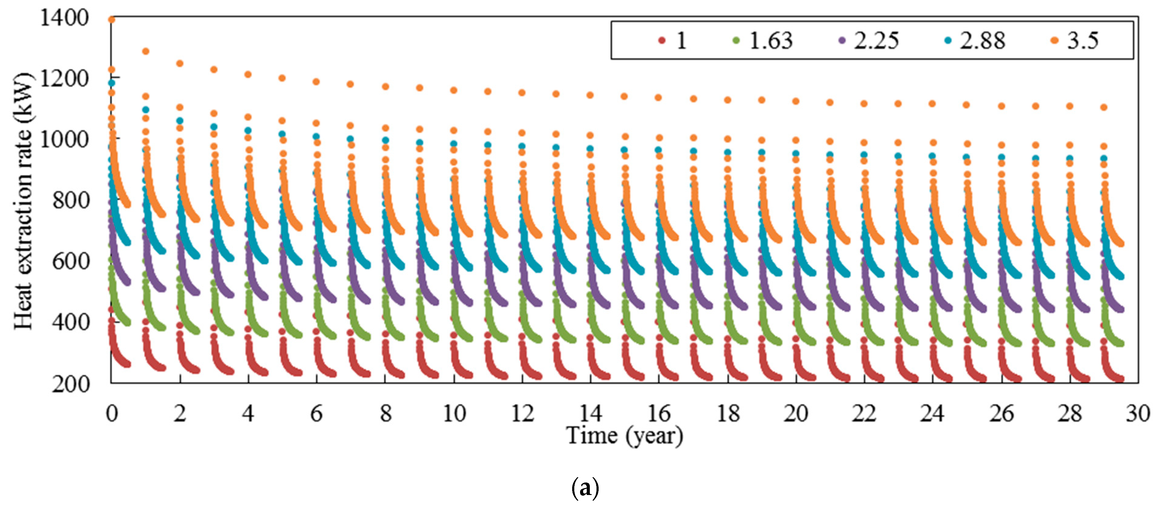
3.4. Ground Thermal Conductivity
To investigate the effect of ground thermal conductivity on the thermal performance of deep horizontal BHEs, five different rock thermal conductivities including 1.00, 1.63, 2.25, 2.88, and 3.50 have been considered in this study. All the other parameters remain as for the base case (
Table 7). The heat extraction rate and borehole wall temperature over time in continuous mode for five different rock thermal conductivities have been demonstrated in
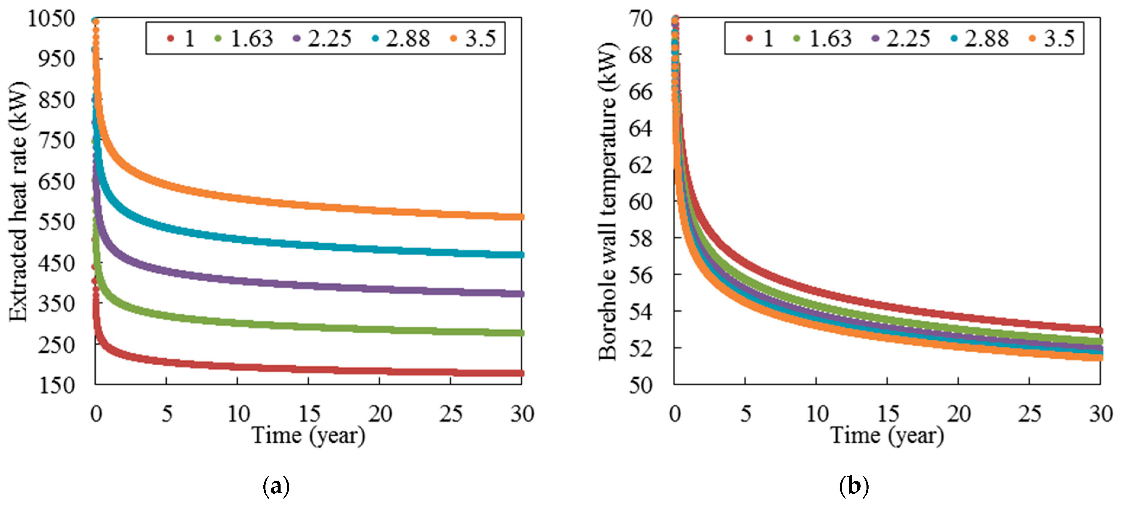
Figure 13. According to this figure, the ground thermal conductivity plays a pivotal role in determining the heat extraction rate while it does not change the borehole wall temperature significantly. At the end of the 30th year, the heat extraction rate is 176, 276, 372, 466, and 559 and the borehole wall temperature is 52.9, 52.3, 51.9, 51.6, and 51.4 when the ground thermal conductivity is 1.00, 1.63, 2.25, 2.88, and 3.50, respectively.
Figure 14 presents the heat extraction rate and borehole wall temperature over time in intermittent mode for five different rock thermal conductivities. According to this figure, the effect of ground thermal conductivity on the thermal performance of deep horizontal borehole in intermittent mode is similar to that in continuous mode. Moreover, it can be seen that by decreasing the ground thermal conductivity, the system reaches a quasi-steady state condition sooner. In this regard, it can be seen that the variation of heat extraction rate in each cycle increases when ground thermal conductivity is increased. In the first six months of 30th year, the difference between maximum and minimum of heat extraction rate is 177, 253, 322, 386, and 447 kW and the difference between maximum and minimum of borehole wall temperature is 23.0, 20.5, 19.0, 17.9, and 17.1 when the ground thermal conductivity is 1.00, 1.63, 2.25, 2.88, and 3.50 W/m·K, respectively. According to this figure, the ground thermal conductivity does not have a significant effect on the borehole wall temperature in recovery mode. For example, the maximum borehole wall temperature at the end of 30th year is 98.7, 99.8, 100.5, 100.9, and 101.3 °C when the ground thermal conductivity is 1.00, 1.63, 2.25, 2.88, and 3.50 W/m·K, respectively, so there is a small difference between borehole wall temperatures of different rock thermal conductivities.
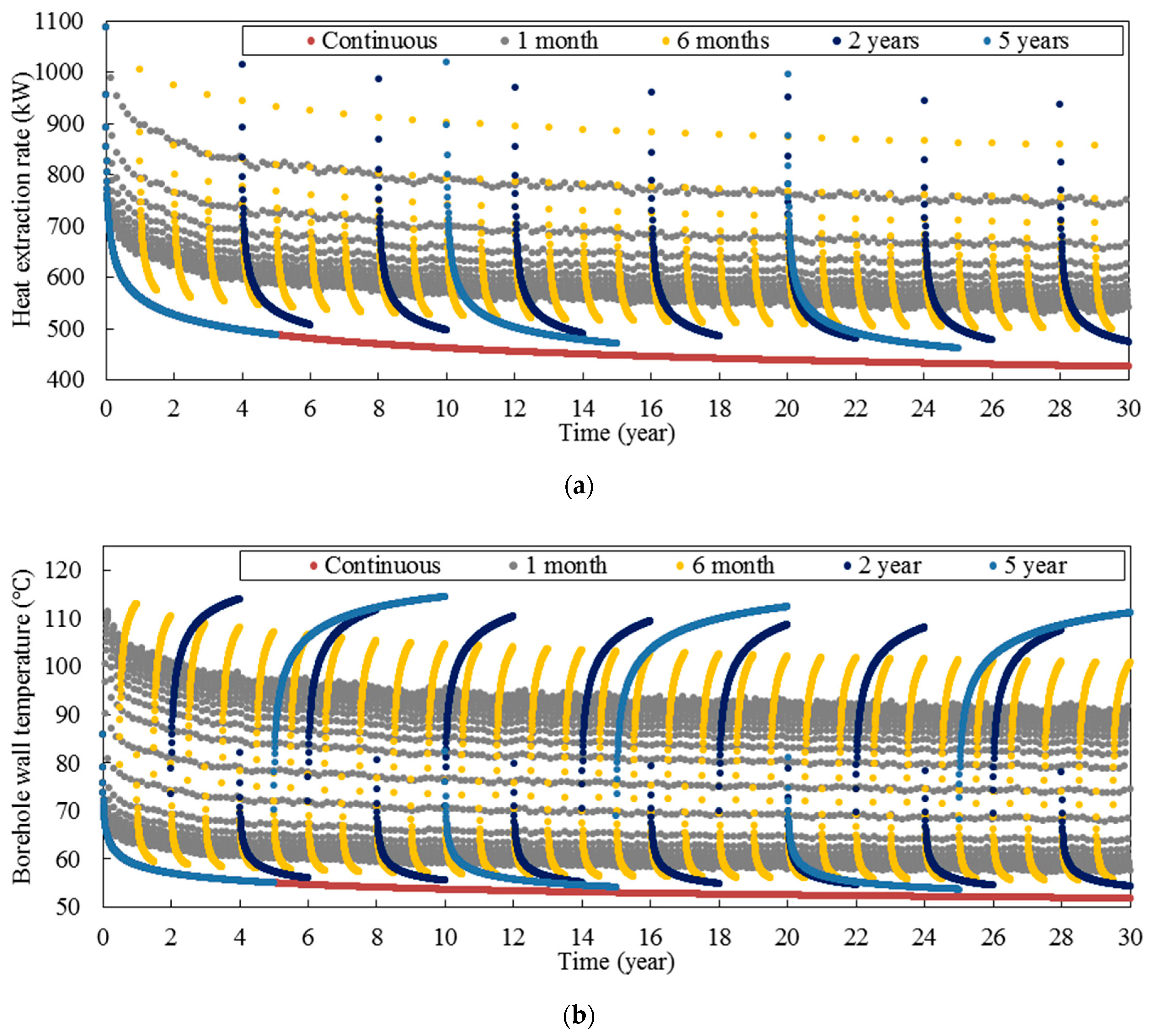
3.5. Periodic Time Interval
In order to study the effect of periodic time interval, six different periodic time intervals including 1 week, 1 month, 6 months, 1 year, 2 years, and 5 years have been considered. It should be noted that all the parameters except the periodic time interval in this section are the same with base case (
Table 7).
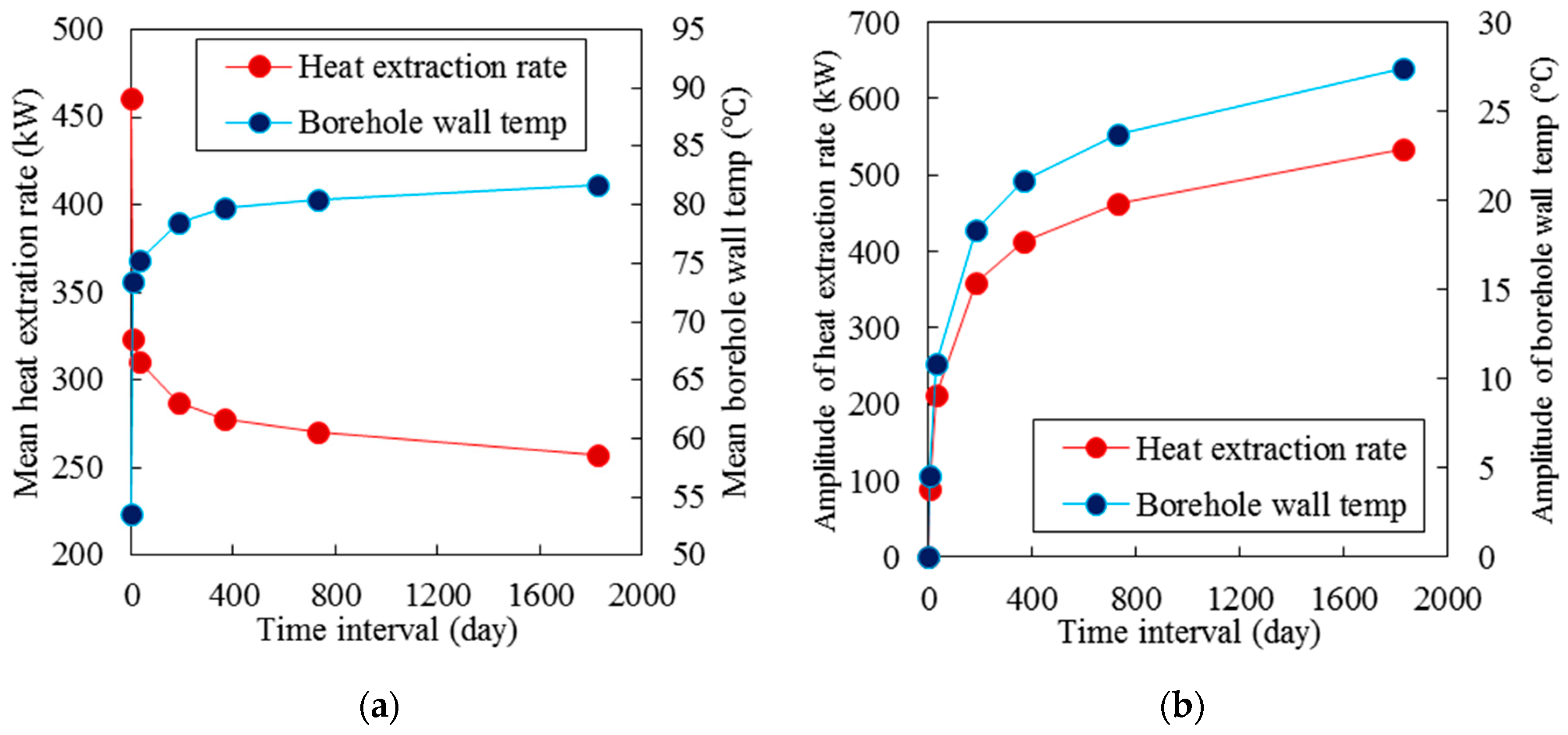
Figure 15 shows the long-term performance of deep horizontal BHE for different periodic time intervals. According to this figure, the periodic time interval affects the heat extraction rate and borehole wall temperature significantly. First of all, the periodic time interval changes the mean heat extraction rate and borehole wall temperature over 30 years. To study better, the mean heat extraction rate and the mean borehole wall temperature over 30 years have been shown in
Figure 16b. According to this figure, by increasing periodic time interval, the mean heat extraction rate is decreased, and the mean borehole wall temperature is increased. However, this trend is not linear, so by increasing periodic time interval, the mean heat extraction rate and the mean borehole wall temperature reach constant values. Moreover, it can be seen in
Figure 15 that periodic time interval changes the variation of heat extraction rate and borehole wall temperature in each cycle significantly. In this regard, according to
Figure 16b, the amplitude of variation of heat extraction rate and borehole wall temperature is increased when the periodic time interval increases. The increment is sharp in short periodic time interval while the increment is significantly reduced in long periodic time interval.
3.6. Flow Rate Ratio
To study the effect of flow rate ratio on the thermal performance of deep horizontal BHEs, six different flow rate ratios including 0.0, 0.2, 0.4, 0.6, 0.8, and 1.0 have been considered in this study. It should be noted that all the parameters except the flow rate ratio in this section are the same with base case (
Table 7).
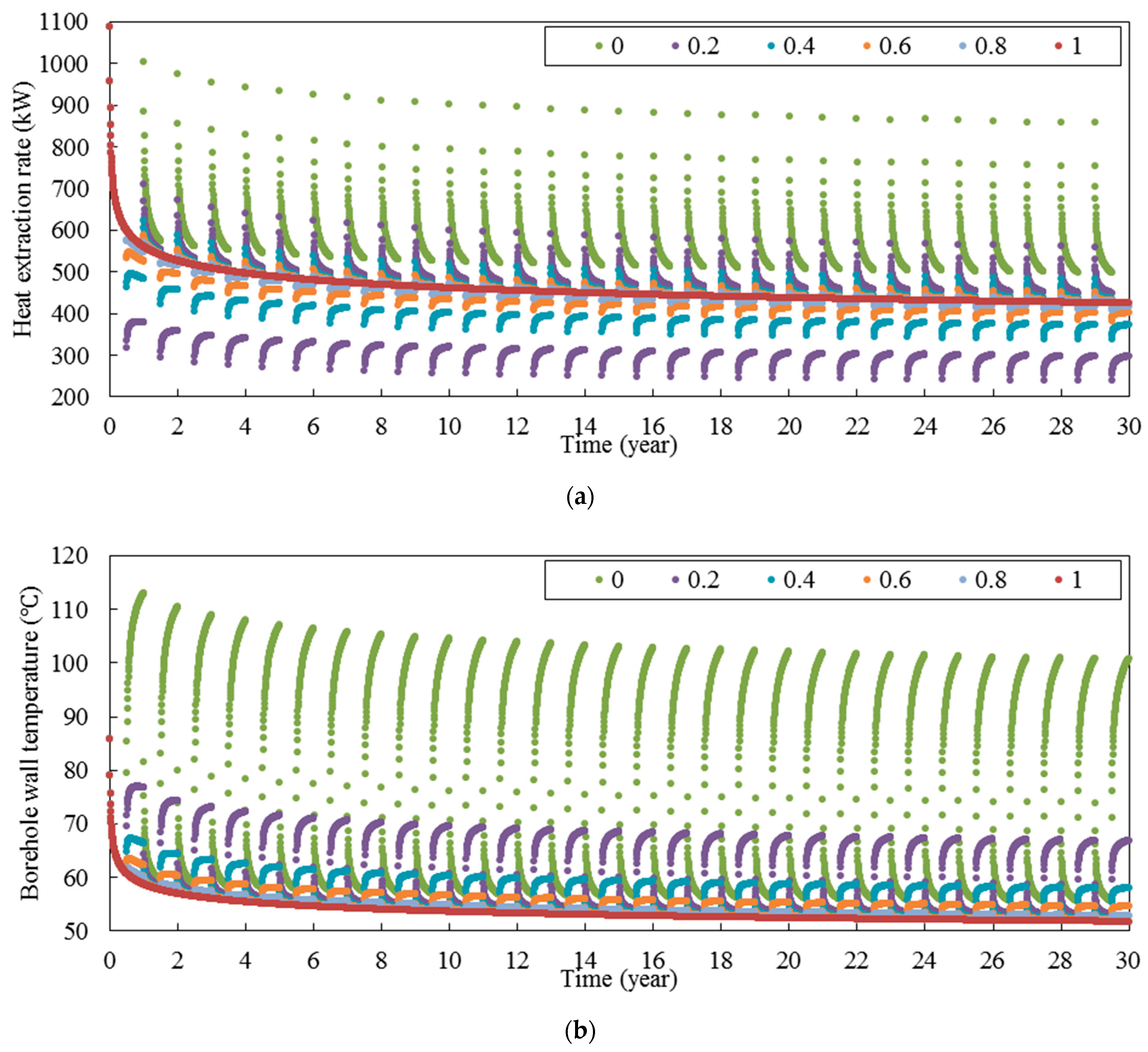
Figure 17 shows the long-term thermal performance of deep horizontal BHE with different flow rate ratios. According to this figure, an interesting thing is for different flow rate ratios except 0, the heat extraction rate, borehole wall temperature, and outlet fluid temperature are approximately the same in the working period (the first six months of the year). However, in the recovery period (the second six months of the year), there is a significant difference between thermal performances of each flow rate ratio. This issue can be seen in
Figure 17b. According to this figure, the maximum borehole wall temperature in the second six months of the 30th year is 100.7, 66.9, 58.0, 54.6, 52.8, and 51.8 °C when the flow rate ratio is 0.0, 0.2, 0.4, 0.6, 0.8, and 1.0, respectively. Thus, there is a significant difference between borehole wall temperatures with flow rate ratio of 0 and 0.2. The similar trend can be seen in
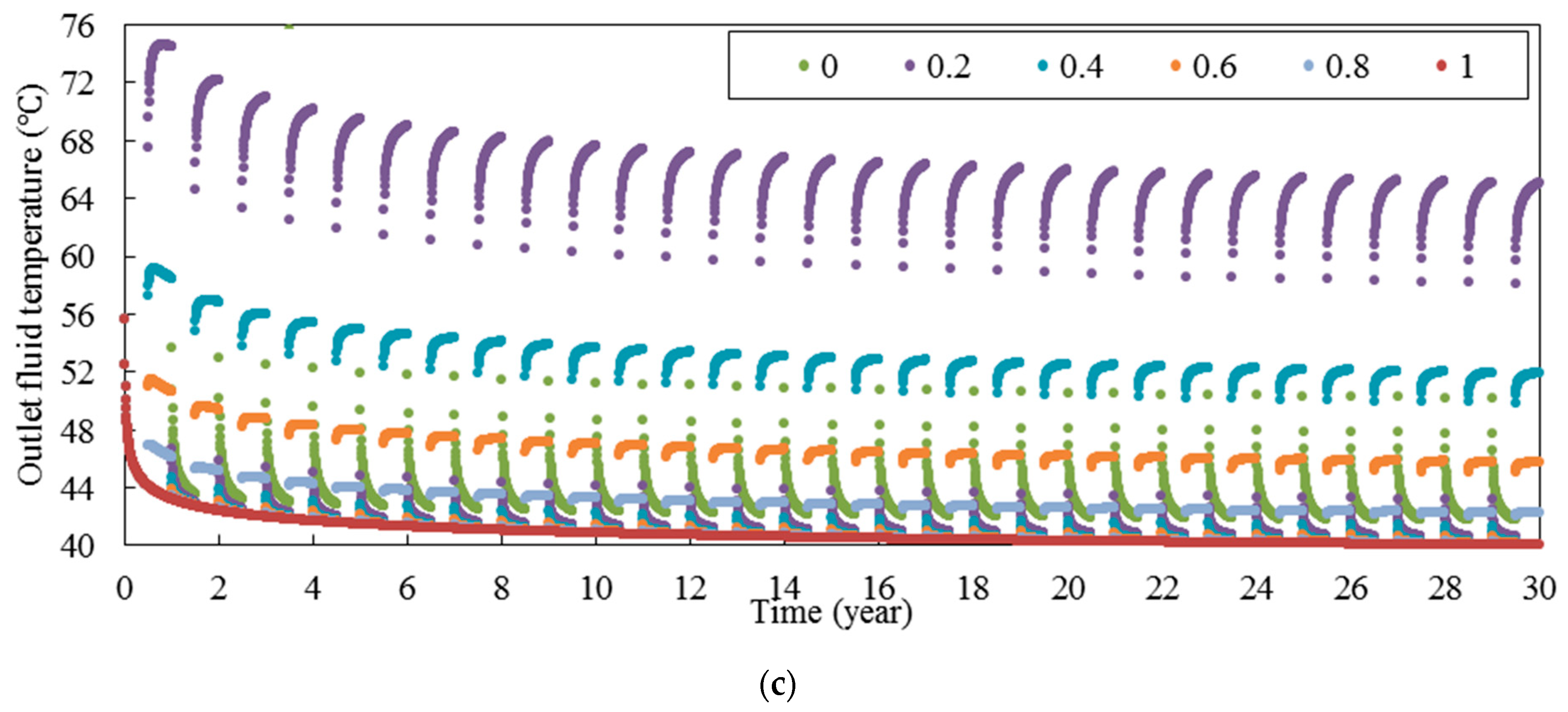
Figure 17c for outlet fluid temperature. According to this figure, the maximum outlet fluid temperature in the second six months of the 30th year is 65.0, 51.9, 45.7, 42.2, and 40.0 °C when the flow rate ratio is 0.2, 0.4, 0.6, 0.8, and 1.0, respectively.
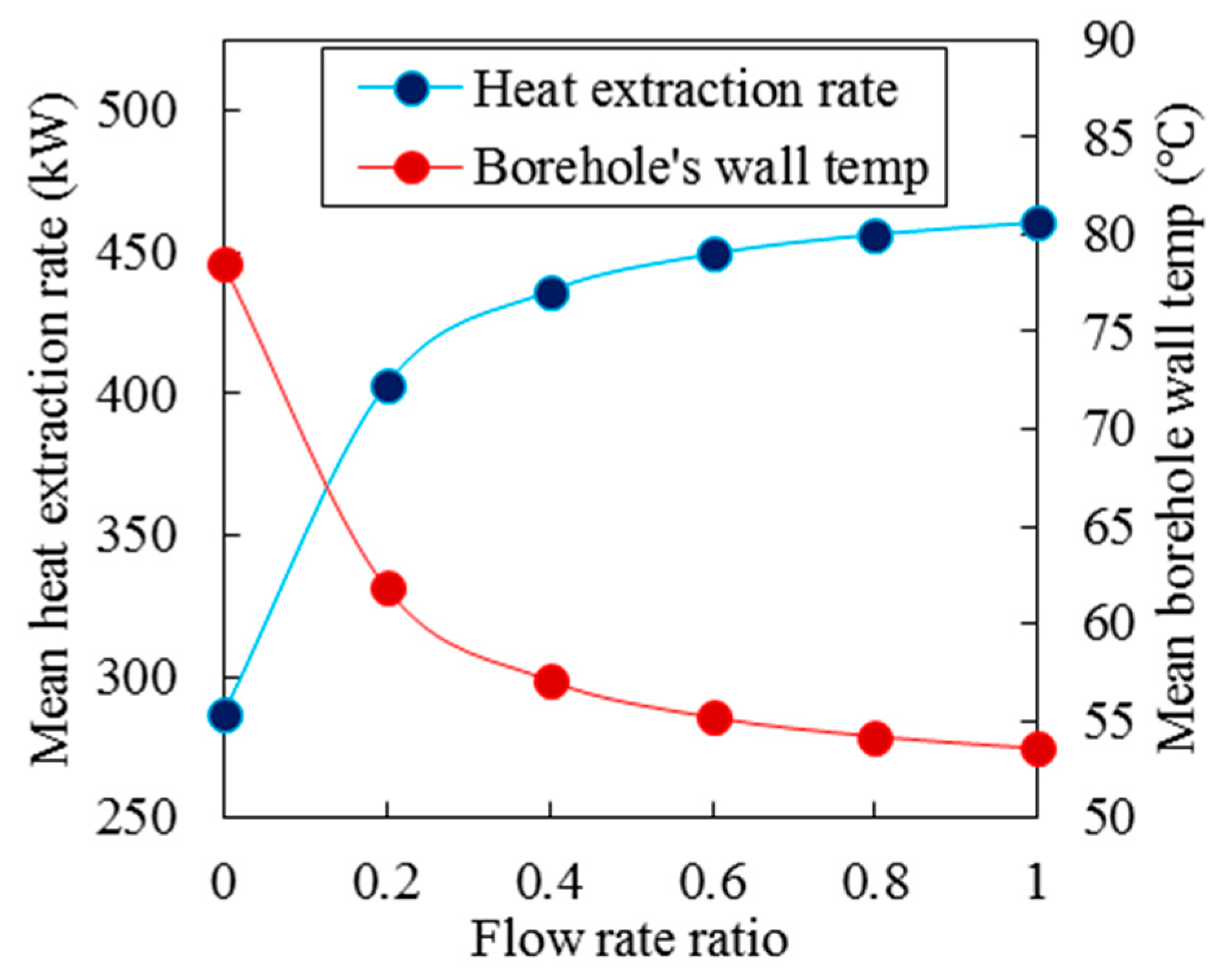
To study better the effect of flow rate ratio on the thermal performance of deep horizontal borehole heat exchangers, the mean heat extraction rate and mean borehole wall temperature in the period of 30 years over the flow rate ratios are plotted in
Figure 18. According to this figure, by increasing the flow rate ratio, the mean heat extraction rate in the period of 30 years is increased and the mean borehole wall temperature in this period is decreased. The increment of mean heat extraction rate and the reduction of mean borehole wall temperature is high at the smaller flow rate ratio but by increasing flow rate ratio, the increment and reduction are decreased.
3.7. Recovery Period Ratio
To investigate the effect recovery period ratio on the thermal performance of deep horizontal BHEs, five different recovery period ratios, including 0.0, 0.2, 0.4, 0.6, and 0.8 have been considered in this study. All other parameters are the same as for the base case (
Table 7).
Figure 19 shows the heat extraction rate and borehole wall temperature in the period of 30 years for different recovery period ratios. According to this figure, by increasing the recovery period ratio, the heat extraction rate, and borehole wall temperature are increased. Moreover, the variation of heat extraction rate in each cycle is increased when recovery period ratio is increased. For example, the variation of heat extraction rate is 1, 275, 338, 375, and 381 kW when the recovery period ratio is 0.0, 0.2, 0.4, 0.6, and 0.8, respectively. Furthermore, it can be seen that the difference between each case is increased when the time is passed. According to
Figure 19b, in the working period, the difference between the borehole wall temperatures of different recovery period ratios is small while in the recovery period, this difference is significantly larger. In this regard, the minimum temperature of borehole wall in the working period of 30th year is 51.8, 52.9, 54.5, 56.9, and 60.9 °C when the recovery period ratio is 0.0, 0.2, 0.4, 0.6, and 0.8, respectively. On the other hand, the maximum temperature of borehole wall in recovery period of 30th year is 51.8, 89.4, 97.3, 104.2, and 111.2 °C when the recovery period ratio is 0.0, 0.2, 0.4, 0.6, and 0.8, respectively.
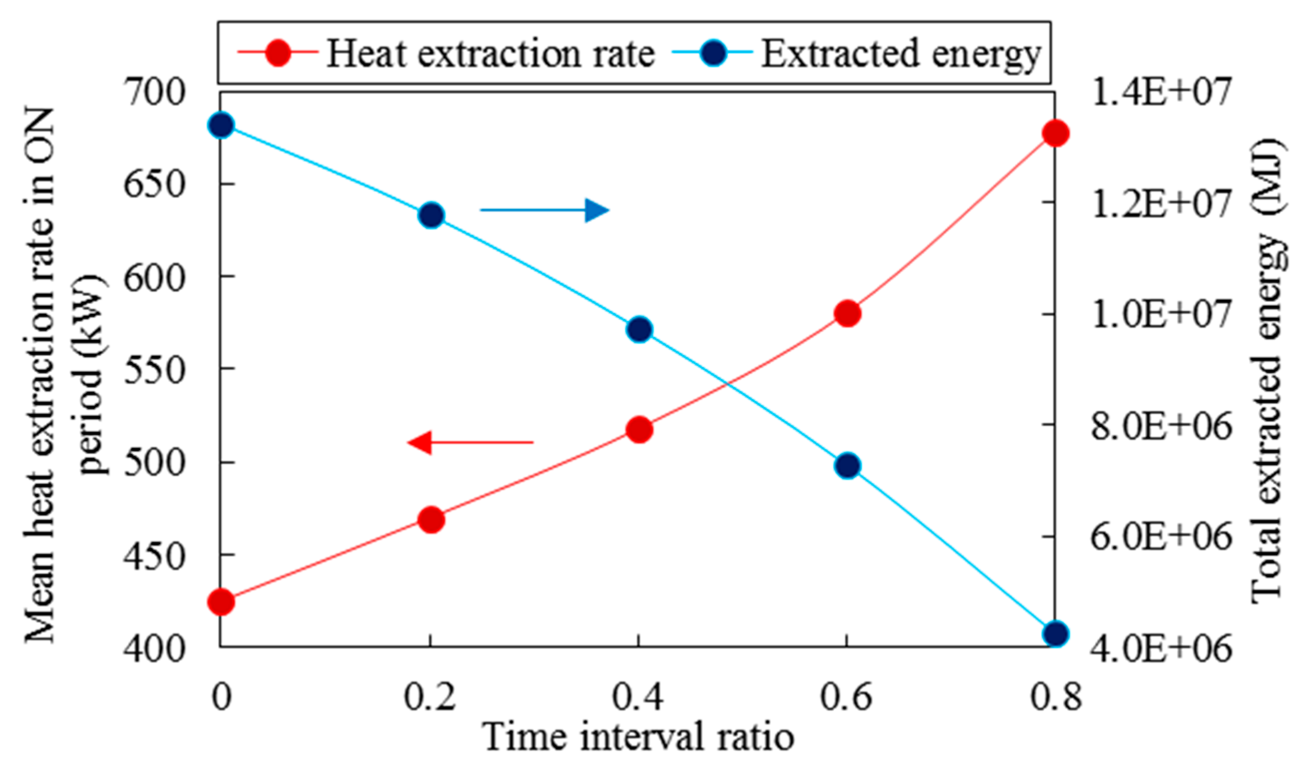
To study better the effect of recovery period ratio on the long-term performance of deep horizontal borehole heat exchangers, the mean heat extraction rate in the working period of 30th year and total extracted energy in the 30th year for different recovery period ratios are plotted in
Figure 20. According to this figure, by increasing the recovery period ratio, the heat extraction rate increases significantly while the total extracted energy decreases. For example, when the recovery period ratio increases from 0.2 to 0.6, the mean heat extraction rate is increased 24% while total extracted energy is decreased 38%.
4. Conclusions
In this study, the long-term performance of horizontal BHE in intermittent mode is scrutinized. In this regard, to predict the transient heat transfer process in the BHEs, a mathematical model is developed and then verified by using the experimental results. The effect of various key parameters including the flow rate of circulating fluid, undisturbed ground temperature, inlet fluid temperature, ground thermal conductivity, periodic time interval, flow rate ratio, and recovery period ratio on the thermal performance of BHE in continuous and intermittent mode is studied. A summary of the key results obtained is as follows:
Increasing the flow rate augments the heat extraction rate because by increasing the flow rate, the temperature difference between fluid and rock reservoir increases, so the heat exchange rate is improved.
By increasing the undisturbed ground temperature, the heat extraction rate and borehole wall temperature are increased significantly. Moreover, in intermittent mode, when undisturbed ground temperature is increased, the variation of heat extraction rate and borehole wall temperature is also increased.
Increasing the inlet fluid temperature decreases the heat extraction rate and increases the outlet water temperature and borehole wall temperature. Furthermore, the variation of heat exchange rate and borehole wall temperature in each year is increased when the inlet fluid temperature decreases.
Although the ground thermal conductivity plays a pivotal role in determining the heat extraction rate, it does not change the borehole wall temperature significantly. In addition, by decreasing the ground thermal conductivity, the system reaches a quasi-steady state condition sooner.
Increasing the periodic time interval reduces the mean heat extraction rate and increases the mean borehole wall temperature. Furthermore, the amplitude of variation of heat extraction rate and borehole wall temperature is increased when the periodic time interval increases. The increment is sharp in short periodic time interval while the increment is reduced in long periodic time interval significantly.
Increasing the flow rate ratio increases the mean heat extraction rate and decreases the mean borehole wall temperature over the period of 30 years. Moreover, the heat extraction rate, borehole wall temperature, and outlet fluid temperature are approximately the same in the working period for different flow rate ratios while there is a significant difference between thermal performances of each flow rate ratio in the recovery period.
Increasing the recovery period ratio increases the heat extraction rate and borehole wall temperature. Furthermore, the variation of heat extraction rate in each year is increased when the recovery period ratio is increased. In addition, although increasing the recovery period ratio increases the heat extraction rate significantly, it reduces the total extracted energy noticeably.
Each of the above observations enhances our current state of knowledge of how BHE’s perform. To some extent, the results on intermittent operation are intuitive. Operating intermittently allows some recovery of the reservoir temperature in between heat extraction. However, we have seen that these techniques can have significant effects on heat extraction rate and amount. Thus, our results provide insight into the different ways in which such can be used.
One of the novel aspects of our study was the focus on deep BHE’s designed for well parameters similar to those in British Columbia, Canada (see
Section 1.1). This case study approach does not give clear answers regarding the feasibility of repurposing wells. Although we believe the conclusions drawn from the models are robust, these simply give data for different modes of usage. Slightly different model assumptions or parameters would give outputs in the same ranges as here we feel.
It is largely up to the potential energy user to complete the feasibility. For example, for agricultural usage a seasonal intermittent extraction would be appropriate (see e.g.,
Figure 15). A single well could provide over 500 kW during its 30-year lifetime, with winter extraction only, to be used for background greenhouse heating or cattle sheds. Many wells in this region are pad-drilled, meaning that the well heads of 5–10 wells are in close proximity on the surface. This allows either alternating continuous power or grouped higher power, e.g., 5 MW. Viewed differently, this is sufficient to heat a small rural Canadian town. Consequently, we feel there is sufficient merit to encourage further exploration of these possibilities.


