Article

Adaline-Based Control Schemes for Non-Sinusoidal Multiphase Drives—Part II: Torque Optimization for Faulty Mode

1
University Lille, Arts et Métiers Institute of Technology, Central Lille, Junia, ULR 2697-L2EP, F-59000 Lille, France
2
Faculty of Electrical Engineering, Thai Nguyen University of Technology, No. 666, 3-2 Street, Thai Nguyen 250000, Vietnam
*
Author to whom correspondence should be addressed.
Energies 2022, 15(1), 249; https://doi.org/10.3390/en15010249
Submission received: 22 November 2021 / Revised: 25 December 2021 / Accepted: 26 December 2021 / Published: 30 December 2021

Abstract

:
Fault tolerance has been known as one of the main advantages of multiphase drives. When an open-circuit fault happens, smooth torque can be obtained without any additional hardware. However, a reconfiguration strategy is required to determine new reference currents. Despite advantages of non-sinusoidal electromotive forces (NS-EMFs) such as high torque density, multi-harmonics existing in NS-EMFs cause more challenges for control, especially under faulty conditions. Therefore, to guarantee high-quality vector control of multiphase drives with multi-harmonic NS-EMFs, this two-part study proposes control schemes using adaptive linear neurons (Adalines) to adaptively eliminate torque ripples. The proposed simple Adalines are efficient because of taking advantage of the knowledge of rotor position and of torque harmonic rank induced by the NS-EMFs. The control scheme using an Adaline for healthy mode was described in part I of this study. In this second part, the control scheme using another Adaline for an open-circuit operation, under the impacts of multi-harmonics in NS-EMFs, is proposed. Notably, smooth torque and similar copper losses in the remaining healthy phases can be obtained. Experimental tests are carried out on a seven-phase permanent magnet synchronous machine (PMSM) with a high total harmonic distortion (THD = 38%) of NS-EMFs. A demonstration video is provided with this paper.

1. Introduction

In applications requiring high functional reliability and high torque density such as electric vehicles, submarines, and aircrafts, the use of multiphase PMSMs is a promising solution. With a high number of phases (>3), multiphase machines have more degrees of freedom for design and control compared with the conventional three-phase machines, especially fault tolerance [1,2,3]. A n-phase symmetrical machine is characterized by (n − 1)/2 (when n is odd) and (n − 2)/2 (when n is even) orthogonal planes, known as two-dimensional reference frames [4]. In healthy mode, each of these reference frames is associated with a group of harmonics of currents and back electromotive forces (back-EMFs). As presented in the first part of this study, under healthy condition, the rotor field-oriented control (RFOC) technique with the classical proportional integral (PI) controllers to control multiphase drives are facilitated if constant reference d-q currents are used. Nevertheless, NS-EMFs possibly contain more harmonics [5,6,7,8], leading to unexpected torque ripples. A solution, named maximum torque per ampere (MTPA), with optimal currents for healthy mode obtained in [9,10,11] was compared with the proposed scheme using an Adaline in the first part of this study [12].
When phases are open-circuited, the number of active phases is reduced and the repartition of harmonics of the current in different d-q frames is no more verified. Currents are no longer properly controlled as in healthy mode due to the coupling between reference frames, leading to the requirement of new reference currents. In addition, the impact of multi-harmonics in back-EMFs on torque quality becomes more complex than in the healthy condition since new harmonics are generated in each two-dimensional reference frame. A review of literature showed that there are many strategies which determine new reference currents to generate smooth torque under faulty conditions. These strategies can be classified into three main approaches as follows.
In the first approach, new current references are determined in a natural frame. This means that new reference currents of the remaining healthy phases are directly determined. The main advantage of the first approach is that a constant torque can be theoretically obtained regardless of multi-harmonics in NS-EMFs by considering a very large width band of current controllers. Conventionally, optimal currents with lowest copper losses can be calculated by MTPA for faulty mode in [9,10] or [11]. Specifically, ref. [9] applies Lagrangian multipliers and [10] uses the vectorial approach while [11] takes advantage of an Adaline. However, despite using different approaches, optimal reference currents in [9,10,11] are the same. These currents have high-frequency oscillating values in d-q frames, posing challenges for current control with PI controllers at high speed. In addition, current waveforms as well as copper losses of the remaining healthy phases are unidentical, possibly leading to the overheating of the remaining phase windings. Recently, ref. [13] for five-phase PMSMs and [14] for general multiphase PMSMs applied the instantaneous power approach to determine additional components to phase currents, reducing torque ripples in faulty modes. The approach in [13,14] has been verified by finite element without considering controllers. As in [9,10,11], studies [13,14] result in varying reference to d-q currents.
In the second approach, main reference d-q currents, generating most of the torque, are kept constant as in healthy mode. The second approach can facilitate current control of main d-q currents with PI controllers at high speed. However, other d-q currents which generate marginal torques are forcedly time-variant. These varying d-q currents not only cause control problems at high speed but also create inevitable torque ripples with multi-harmonic NS-EMFs. Indeed, in [15,16] for multiphase induction machines and in [17,18,19] for five-phase PMSMs, only sinusoidal back-EMFs have been considered, hence, constant torque can be obtained. In [20], with more degrees of freedom in seven-phase PMSMSs, NS-EMFs with the first and third harmonics can generate smooth torque. However, in [21], NS-EMFs contain three harmonics, the torque ripple is high (>30% in [21]) due to the interaction between the varying d-q currents and corresponding harmonics of NS-EMFs. Therefore, the second approach cannot properly deal with multi-harmonics existing in NS-EMFs.
Finally, the third approach uses new transformation matrices to find new reference currents. Indeed, when one phase is open-circuited, a n-phase machine can be considered as a (n − 1)-phase machine with reduced-order Clarke and Park transformation matrices. For example, studies [22,23] proposed new matrices for sinusoidal back-EMF multiphase machines but these studies cannot be applied for NS-EMF machines due to high-ripple torque. A strategy using two Clarke and two Park matrices can be found in [24] for five-phase NS-EMF PMSMs in which the first and third harmonic components of current and NS-EMFs are considered to generate smooth torque. Meanwhile, studies [25,26] use only one Clarke and one Park matrix to generate non-sinusoidal reference currents. However, the control challenge of varying reference d-q currents in [24,25,26] is similar to strategies in the first approach. Recently, ref. [27] proposed a control scheme using new transformation matrices and an Adaline in which constant reference d-q currents can be used for control in faulty mode, keeping PI controllers as in healthy mode. However, in general, the third approach cannot eliminate torque ripples caused by plenty of harmonics in NS-EMFs.
In the three above approaches, only the first approach with the conventional MTPA strategy can generate smooth torque under the impact of multi-harmonics in NS-EMFs. Therefore, MTPA strategy will be used to compare with the proposed strategy and control scheme in this study. As previously mentioned, the control of varying reference d-q currents at high speed and unidentical copper losses in the remaining healthy phases are challenges for MTPA strategy. Controllers whose bandwidth increases with the rotating speed have been used to control varying currents. Specifically, hysteresis controllers have been used in [9,10] but these controllers lead to variable switching frequencies, high switching losses, and electromagnetic compatibility problems. Resonant PI (PIR) controllers can be another solution to track varying currents in [25,26] for five-phase PMSMs and [28,29] for five-phase induction machines. However, PIR requires accurate frequency estimations and tuning procedures with many parameters. Therefore, in faulty mode, the existing MTPA strategy used in the conventional RFOC scheme with PI controllers will be utilized to compare with the proposed control scheme in this study.
In this part of the study, a control scheme is proposed for multiphase machines considering multi-harmonics of NS-EMFs in a post-fault operation. The proposed control scheme for the post-fault operation combines the conventional RFOC technique using PI controllers, one Adaline, and a fault-tolerant strategy with equal copper losses (ECL). The Adaline is used owing to its self-learning, fast convergence, and simplicity [27,30]. It exploits the information about the rotor position and torque harmonic components to adaptively eliminate torque ripples. Therefore, smooth torque can be obtained regardless of multi-harmonic NS-EMFs. Compared with PIR, the Adaline has less parameters (only learning rate) which need to be properly chosen, other parameters of Adaline can be automatically updated. In addition, compared with the conventional RFOC using MTPA strategy [
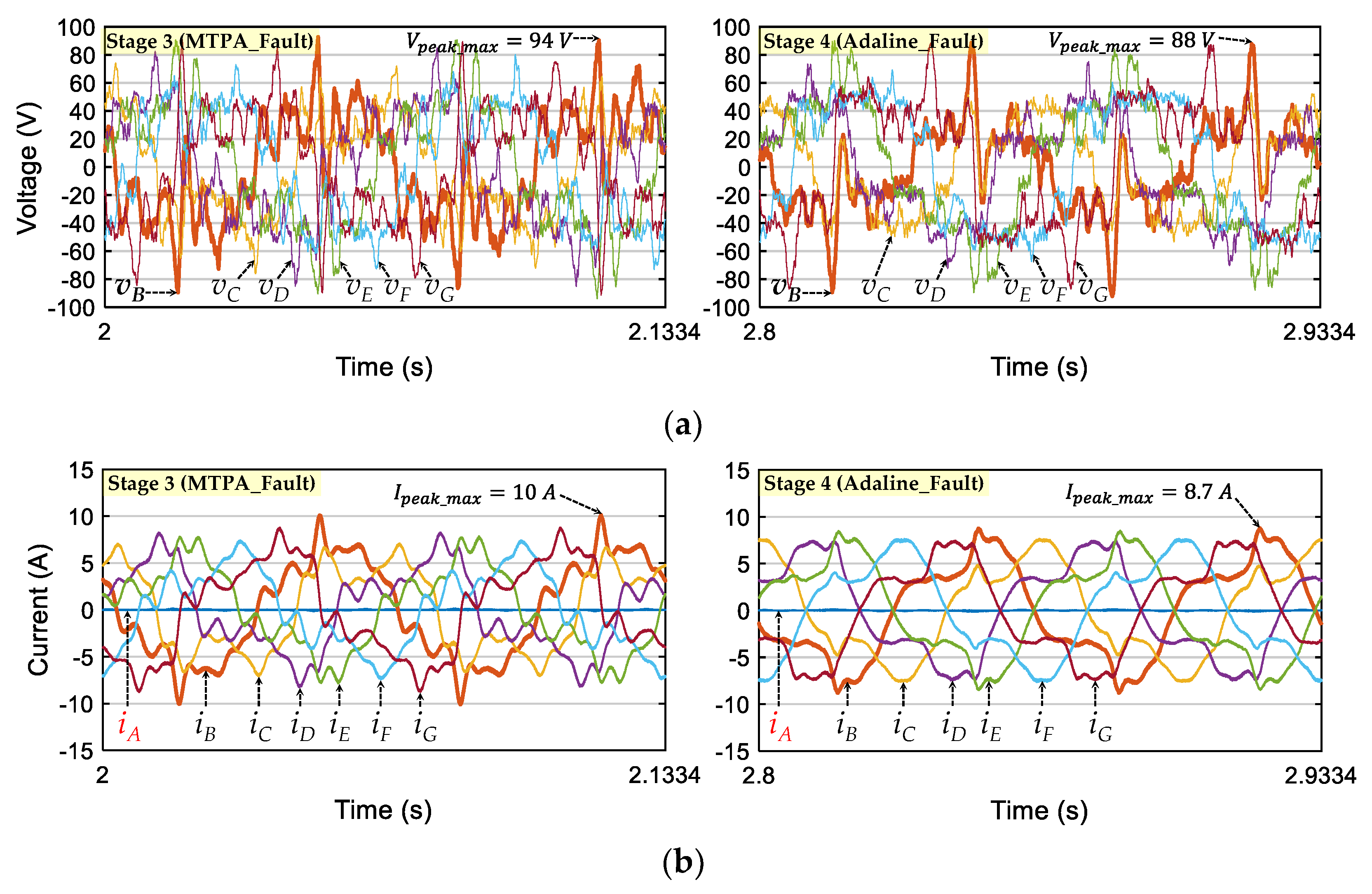
9,10], ECL strategy used in the proposed Adaline-based control scheme allows more similar copper losses in the remaining healthy phases, avoiding the overheating of the remaining phase windings. Besides, with the proposed control scheme, new reference d-q currents have less high-order harmonic components. Therefore, the proposed Adaline-based control scheme with ECL strategy has higher control quality and phase currents in the remaining healthy phases containing less high-frequency harmonics.
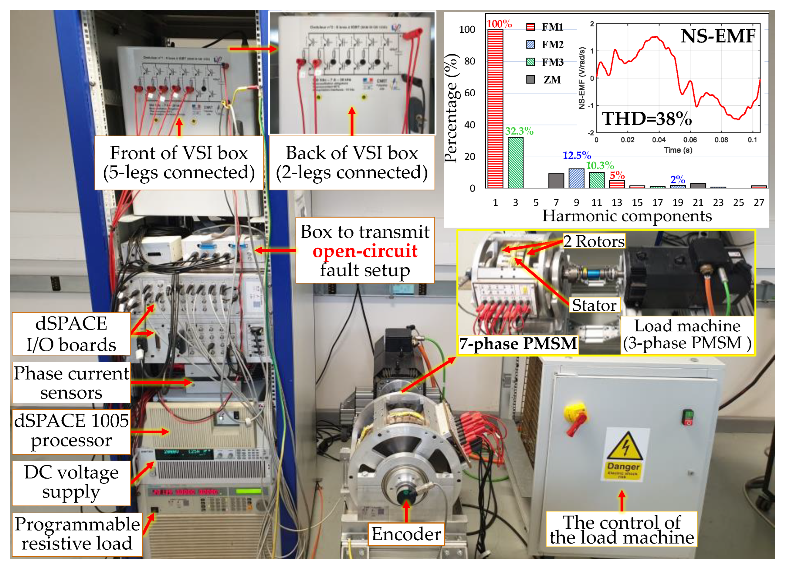
The proposed Adaline-based control scheme using ECL strategy is numerically and experimentally tested on a seven-phase PMSM with a high THD of NS-EMFs. As previously mentioned, the proposed scheme is compared with the conventional RFOC using the MTPA strategy to prove its superiority. A single-phase open-circuit condition is presented but this proposed scheme can guarantee smooth torque for more opened phases. Moreover, these schemes are applicable to any electric machine with an arbitrary number of phases. A Video S1 to demonstrate the operation of the experimental test bench is provided with this part of the study.
This paper is organized as follows. Modeling of a seven-phase machine, previously presented in part I of this study, is briefly re-described in Section 2. The conventional RFOC scheme using MTPA for faulty mode is discussed in Section 3. Section 4 describes the proposed control scheme using an Adaline and ECL strategy for faulty mode. Numerical and experimental results are presented in Section 5.

2. Modeling of a Seven-Phase PMSM

To model and control a seven-phase PMSM, several assumptions are considered as follows: seven star-connected phase windings are equally shifted; NS-EMFs consist of more than (n − 1)/2 = 3 harmonics with the highest proportions belonging to 1st, 3rd, and 9th; and the saturation of magnetic circuits is not considered in NS-EMF and flux calculations.
The phase voltages can be expressed as follows:
v _ = R i _ + [ L ] d i _ d t + Ω e _ s n with   { v _ = [ v A v B v C v D v E v F v G ] T i _ = [ i A i B i C i D i E i F i G ] T e _ s n = [ e A e B e C e D e E e F e G ] T
where v, i, and esn are the 7-dimensional vectors of phase voltages, phase currents, and speed-normalized NS-EMFs, respectively; R is the resistance of the stator winding of one phase; [L] is the 7-by-7 stator inductance matrix; and Ω is the rotating speed of the rotor.
In the conventional RFOC technique, Clarke and Park matrices [4,10,20,21] are applied to transform parameters of the machine from natural frame into decoupled rotor reference frames (d-q frames), as previously presented in the first part of this study. With the considered seven-phase prototype, the 1st, 3rd, and 9th harmonics have the highest amplitudes in NS-EMFs, leading to the transformation for currents as follows:
i _ d q = [ P ] [ T ] i _ with   i _ d q = [ i d 1 i q 1 i d 9 i q 9 i d 3 i q 3 i z ] T
where idq is the 7-dimensional vector of currents in d-q frames; (id1, iq1), (id9, iq9), (id3, iq3), and iz are currents in two-dimensional frames (d1-q1), (d9-q9), (d3-q3), and zero-sequence frame z, respectively; [T] and [P] are the 7-by-7 Clarke and Park transformation matrices, respectively (see part I of this study).
Consequently, a seven-phase machine is mathematically decomposed into 3 two-phase fictitious machines (FM1, FM2, and FM3) and 1 zero-sequence machine (ZM), corresponding to reference frames (d1-q1), (d9-q9), (d3-q3), and z [4]. In healthy mode, a fictitious machine with its corresponding d-q frames is associated with a group of harmonics in natural frame as described in Table 1. Therefore, harmonic orders presenting in d-q frames of currents or NS-EMFs can be 0 (constant component), 14th, and 28th, as previously described in the first part of this study.
In healthy condition, if there is only one harmonic of NS-EMFs per FM, currents (id1, iq1, id9, iq9, id3, and iq3) are constant to generate constant torque, facilitating the use of PI controllers in the conventional RFOC scheme. When an open-circuit fault happens, the decoupled reference frames become coupled frames. A constant torque is only guaranteed when new complex reference currents are determined.
As previously discussed in the first part of this study, NS-EMFs may contain more than one harmonic per FM. In this case, new reference currents for the post-fault operation are more complex. To see impacts of multi-harmonics in NS-EMFs in faulty mode, it is assumed that there are two associated harmonics per FM. Specifically, the considered prototype has the following harmonics:
  • The 1st and 13th are associated with FM1;
  • The 9th and 19th are associated with FM2;
  • The 3rd and 11th are associated with FM3.
In addition, it is assumed that the 1st harmonic of NS-EMFs has the highest amplitude, followed by the 3rd harmonic. Harmonics associated with ZM (7k) have no impact on torque generation due to the star connection (iz = 0).
The speed-normalized NS-EMF of one phase can be rewritten as:
e j = { E n 1 sin [ θ ( j 1 ) 2 π 7 + φ 1 ] + E n 13 sin [ 13 ( θ ( j 1 ) 2 π 7 ) + φ 13 ] } + { E n 9 sin [ 9 ( θ ( j 1 ) 2 π 7 ) + φ 9 ] + E n 19 sin [ 19 ( θ ( j 1 ) 2 π 7 ) + φ 19 ] } + { E n 3 sin [ 3 ( θ ( j 1 ) 2 π 7 ) + φ 3 ] + E n 11 sin [ 11 ( θ ( j 1 ) 2 π 7 ) + φ 11 ] }
where (En1, En13, En9, En19, En3, and En11) and (φ1, φ13, φ9, φ19, φ3, and φ11) are the speed-normalized amplitudes and initial phase angles of back-EMF harmonics 1st, 13th, 9th, 19th, 3rd, and 11th, respectively; j is the phase number from 1 to 7 or from A to G; and θ is the electrical rotor position.
From (1)–(3), the total electromagnetic torque of the machine 
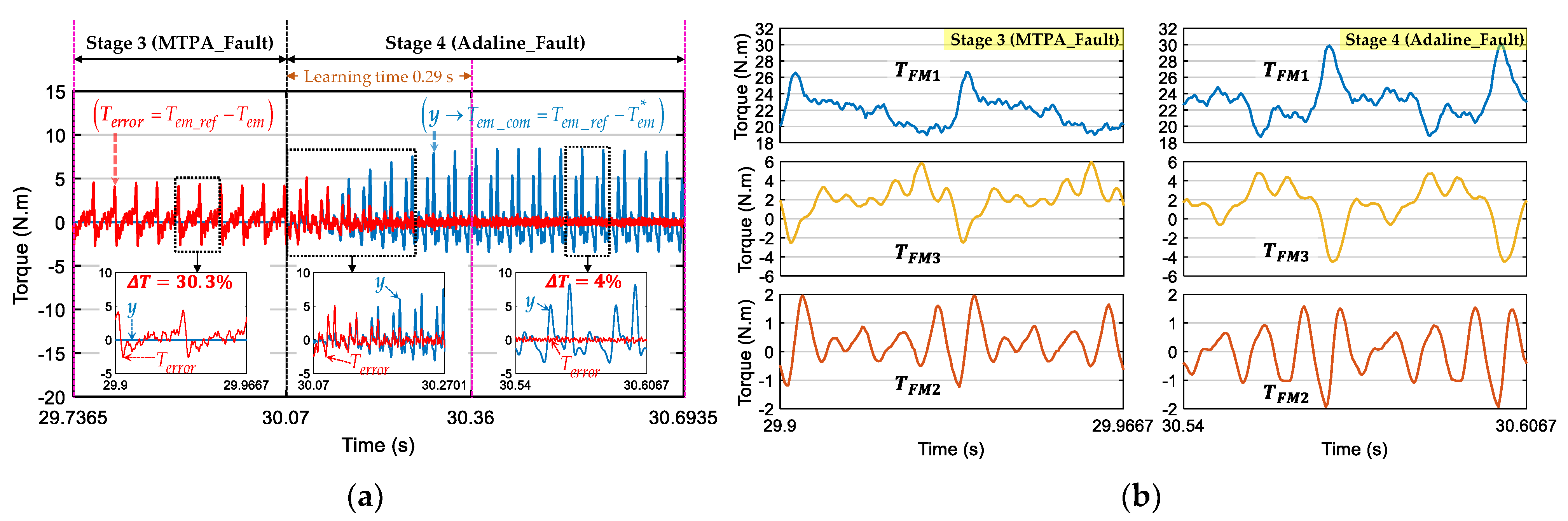
Tem can be expressed as follows:
T e m = e _ s n T i _ = j = A G ( e j i j ) = e _ d q T i _ d q = T F M 1 + T F M 2 + T F M 3
where TFM1, TFM2, and TFM3 are the torques of FM1, FM2, and FM3, respectively; and edq is the 7-dimensional vector of NS-EMFs in d-q frames.

3. Conventional Control of Multiphase Machines for Faulty Mode

3.1. Conventional RFOC Scheme for Faulty Mode

When phase A is open-circuited, its current (iA) is nullified. The conventional RFOC scheme used for healthy mode can be preserved in faulty mode as presented in Figure 1. However, new reference phase currents iref need to be determined to obtain smooth torque. Conventionally, from a given reference torque Tem_ref, MTPA strategy [9,10] or [11] can be used to calculate optimal currents in faulty mode. The reference phase currents are then transformed into d-q frames idq_ref. Speed-normalized NS-EMFs and Park transformations are calculated with the rotor position θ from an encoder. Six PI controllers are used to control six reference d-q currents, generating voltage references. These voltage references are used to generate switching signals for a voltage source inverter (VSI) using the carrier-based pulse width modulation (PWM) strategy.

3.2. Maximum Torque per Ampere for Faulty Mode (MTPA_Fault)

When an open-circuit fault happens, new reference currents need to be determined. Optimal reference currents generating maximum constant torque with minimum total copper losses are obtained by MTPA strategy in [9,10] (“MTPA_Fault”) or [11].
Without loss of generality, when phase A is opened, new reference currents iref for the six remaining healthy phases to generate a constant reference torque Tem_ref are proposed in [10] as follows:
i _ r e f = T e m _ r e f e _ s n _ f e _ z 2 ( e _ s n _ f e _ z ) with   e _ z = 1 n 1 ( j = B G e j ) u _ = 1 6 ( j = B G e j ) u _ ; e _ s n _ f = [ 0 e B e C e D e E e F e G ] T ; u _ = [ 0 1 1 1 1 1 1 ] T
where e _ s n _ f is the 7-dimensional vector derived from e _ s n by setting eA to zero; ez is a 7-dimensional vector to satisfy a null zero-sequence current in the star connection; e _ s n _ f e _ z is the norm of vector ( e _ s n _ f e _ z ) ; and n is the number of phases (n = 7 in this study).
Thereafter, reference phase currents (iref) are transformed into reference d-q currents (idq_ref) by using (2). These reference d-q currents are time-variant and controlled by six PI controllers of the conventional RFOC scheme as described in Figure 1.

4. Proposed Adaline-Based Control Scheme for Faulty Mode

4.1. New Reference Currents with Equal Copper Losses (ECL)

The approach with ECL in the remaining healthy phases was firstly presented in [15] for S-EMFs and sinusoidal currents under an open-circuit fault. The total copper losses are minimized under the constraint on identical amplitudes of the remaining phase currents. In this study, the proposed control scheme for faulty mode is based on ECL strategy but for NS-EMFs and non-sinusoidal currents. New reference phase currents of the remaining healthy phases have the same non-sinusoidal waveform (identical amplitudes and harmonic spectrums). Especially, under a constraint on RMS currents, the identical waveform currents of the remaining healthy phases can generate more torque. In other words, these new reference currents can guarantee copper losses similarly distributed in the remaining healthy phases, avoiding the overheating of phase windings.
For a S-EMF multiphase machine, sinusoidal currents with identical waveforms can be imposed to generate constant torque in faulty mode [15]. With a NS-EMF machine, the presence of torque ripples is inevitable due to the interaction between the 1st harmonic of currents and high-order harmonics of NS-EMFs.
It is assumed that phase A is open-circuited. To simply analyze the torque generation, the speed-normalized NS-EMFs in (3) with only two highest amplitude harmonics (1st in FM1 and 3rd in FM3) can be written as follows:
e j = E n 1 sin [ θ ( j 1 ) 2 π 7 ] + E n 3 sin [ 3 ( θ ( j 1 ) 2 π 7 ) + φ e ]     = E n 1 { sin [ θ ( j 1 ) 2 π 7 ] + k e sin [ 3 ( θ ( j 1 ) 2 π 7 ) + φ e ] }
where ke is the amplitude ratio of the 3rd harmonic to 1st harmonic of NS-EMFs (ke = En3/En1); and φe is the phase shift angle between the 3rd and 1st harmonics of NS-EMFs (φe = φ3φ1).
New sinusoidal reference currents for the six remaining healthy phases are given by:
{ i B = I m 1 sin ( θ + φ B ) i C = I m 1 sin ( θ + φ C ) i D = I m 1 sin ( θ + φ D ) i E = i B i F = i C i G = i D
where Im1 is the amplitude of the 1st harmonic of the six remaining healthy phase currents; φB, φC, and φD are initial phase angles of currents in phases B, C, and D, respectively.
From (4), (6) and (7), the electromagnetic torque Tem is expressed by:
T e m = j = B G ( e j i j ) = T a v e + T 2 θ + T 4 θ with   { T a v e = I m 1 E n 1 sin ( 3 π 7 ) { 2 cos ( φ B φ D 2 2 π 7 ) sin ( φ B + φ D 2 ) sin ( φ C ) } T 2 θ = I m 1 E n 1 { sin ( 3 π 7 ) { 2 cos ( φ B φ D 2 + 2 π 7 ) sin ( 2 θ + φ B + φ D 2 ) sin ( 2 θ + φ C ) } + k e sin ( 9 π 7 ) { 2 cos ( φ B φ D 2 6 π 7 ) sin ( 2 θ φ B + φ D 2 + φ e ) + sin ( 2 θ φ C + φ e ) } } T 4 θ = I m 1 E n 1 k e sin ( 9 π 7 ) { 2 cos ( φ B φ D 2 + 6 π 7 ) sin ( 4 θ + φ B + φ D 2 + φ e ) sin ( 4 θ + φ C + φ e ) }
where Tave is the average torque; and T2θ and T4θ are torque ripples with harmonics 2θ and 4θ, respectively.
From (8), the total torque contains a constant component Tave and harmonic components T2θ and T4θ. With S-EMFs, ke is zero, the total torque becomes constant when the first term of T2θ is nullified. In this case, the required values of φB, φC, and φD are described as follows:
{ φ B = 5 π 42 ;   φ C = π 2 ;   φ D = 37 π 42 }
With NS-EMFs, the presence of the 3rd harmonic (ke > 0) generates an additional term in T2θ and the entire harmonic T4θ. These harmonic components cannot be simultaneously eliminated with sinusoidal currents (no solution). In this case, an injection of the 3rd harmonic of currents can improve the torque quality. Indeed, new non-sinusoidal reference currents containing the 1st and 3rd harmonics for the remaining healthy phases are proposed as follows:
{ i B = I m 1 { sin ( θ + φ B ) + k i sin [ 3 ( θ + φ B ) + φ i ] } i C = I m 1 { sin ( θ + φ C ) + k i sin [ 3 ( θ + φ C ) + φ i ] } i D = I m 1 { sin ( θ + φ D ) + k i sin [ 3 ( θ + φ D ) + φ i ] } i E = i B i F = i C i G = i D
where ki and φi are the amplitude ratio and the phase shift angle of the 3rd harmonic to 1st harmonic of currents, respectively.
From (4), (6) and (10), the total torque generated by NS-EMFs and non-sinusoidal currents can be expressed by:
T e m = j = B G ( e j i j ) = T a v e + T 2 θ + T 4 θ + T 6 θ with { T a v e = I m 1 E n 1 { sin ( 3 π 7 ) { 2 cos ( φ B φ D 2 2 π 7 ) sin ( φ B + φ D 2 ) sin ( φ C ) } + k e k i sin ( 9 π 7 ) { 2 cos ( 3 ( φ B φ D 2 ) 6 π 7 ) sin ( 3 ( φ B + φ D 2 ) + φ i φ e ) sin ( 3 φ C + φ i φ e ) } } T 2 θ = I m 1 E n 1 { sin ( 3 π 7 ) { 2 cos ( φ B φ D 2 + 2 π 7 ) sin ( 2 θ + φ B + φ D 2 ) sin ( 2 θ + φ C ) } + k e sin ( 9 π 7 ) { 2 cos ( ( φ B φ D 2 ) + 6 π 7 ) sin ( 2 θ φ B + φ D 2 + φ e ) + sin ( 2 θ φ C + φ e ) } + k i sin ( 3 π 7 ) { 2 cos ( 3 ( φ B φ D 2 ) 2 π 7 ) sin ( 2 θ + 3 ( φ B + φ D 2 ) + φ i ) sin ( 2 θ + 3 φ C + φ i ) } } T 4 θ = I m 1 E n 1 { k e sin ( 9 π 7 ) { 2 cos ( φ B φ D 2 + 6 π 7 ) sin ( 4 θ + φ B + φ D 2 + φ e ) sin ( 4 θ + φ C + φ e ) } + k i sin ( 3 π 7 ) { 2 cos ( 3 ( φ B φ D 2 ) + 2 π 7 ) sin ( 4 θ + 3 ( φ B + φ D 2 ) + φ i ) sin ( 4 θ + 3 φ C + φ i ) } } T 6 θ = I m 1 E n 1 k e k i sin ( 9 π 7 ) { 2 cos ( 3 ( φ B φ D 2 ) + 6 π 7 ) sin ( 6 θ + 3 ( φ B + φ D 2 ) + φ i + φ e ) sin ( 6 θ + 3 φ C + φ i + φ e ) }
It is noted that the total torque in (11) contains an average torque Tave (constant) and three harmonic components T2θ, T4θ, and T6θ. Due to the 3rd harmonic of currents with ki, the average torque Tave increases an amount proportional to (keki). Meanwhile, the torque harmonics T, T4θ, and T6θ cannot be simultaneously eliminated because there are no solutions under the constraint on identical current waveforms in the six remaining healthy phases in (10). For the sake of simplicity, the initial phase angles in (9) can be used to eliminate the first term of T2θ which has the highest amplitude.
The corresponding torque components in (11) with the initial phase angles in (9) are expressed by:
{ T a v e = I m 1 E n 1 { 2.84 + 1.76 k e k i cos ( φ i φ e ) } T 2 θ = I m 1 E n 1 { 0.9 k e cos ( 2 θ + φ e ) + 0.78 k i cos ( 2 θ + φ i ) } T 4 θ = I m 1 E n 1 { 0.36 k e cos ( 4 θ + φ e ) 0.54 k i cos ( 4 θ + φ i ) } T 6 θ = 2.35 I m 1 E n 1 k e k i cos ( 6 θ + φ e + φ i )
From (12), the average torque increases an amount of [1.76kekiIm1En1cos(φi − φe)] when the 3rd harmonic of currents are injected. The amplitudes of torque harmonics (T2θ, T4θ, and T6θ) are proportional to ke and ki. The phase shift angle φi must be equal to φe to maximize the average torque Tave. The amplitude ratio ki is equal to ke to minimize torque ripples and the rest of torque ripples will be eliminated by the proposed Adaline in the next subsection.
From Tave in (12), the amplitude of the 1st harmonic of reference phase currents can be expressed as:
I m 1 = T a v e ( 2.84 + 1.76 k e k i ) E n 1
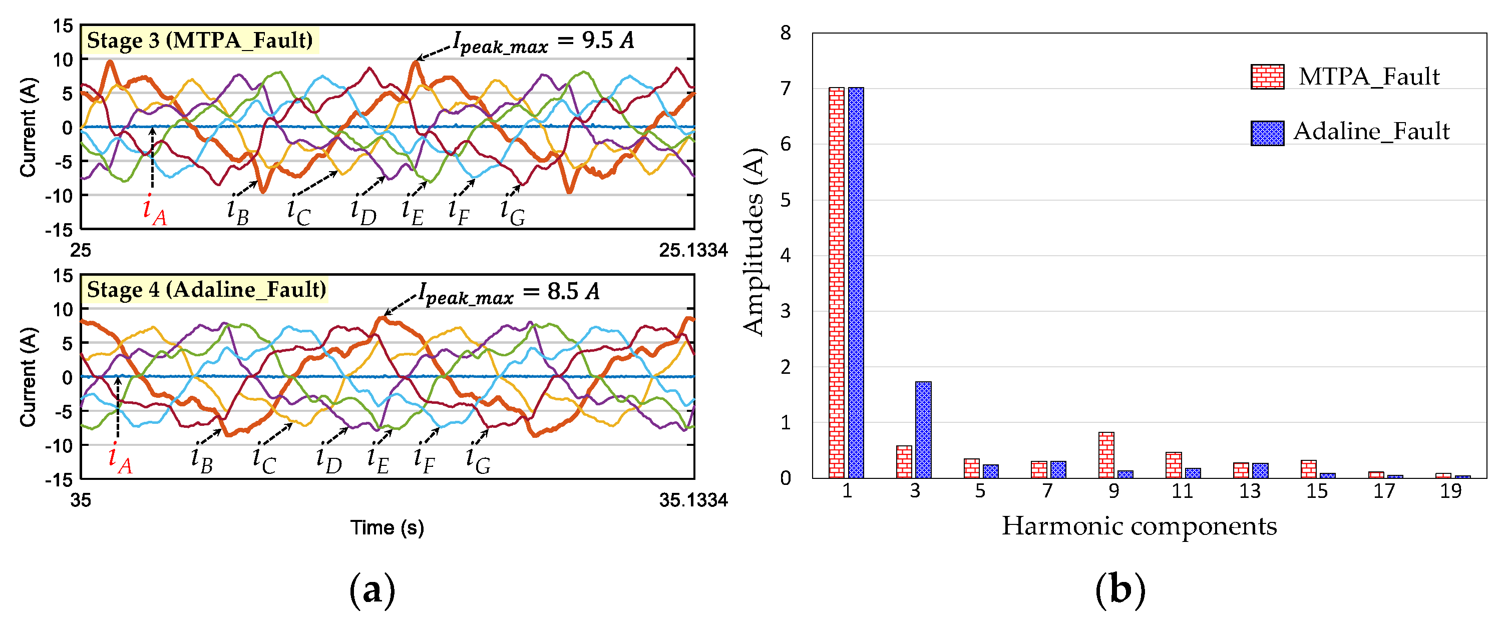
Finally, to generate an average torque Tave, reference non-sinusoidal phase currents for the remaining healthy phases can be determined by using (9), (10) and (13). When NS-EMFs contain only the 1st and 3rd harmonics, the torque ripples with sinusoidal currents include two harmonics 2θ and 4θ as described in (8). Meanwhile, with the injection of the 3rd harmonic of currents, there are three harmonics 2θ, 4θ, and 6θ as described in (11).
In the considered seven-phase prototype, NS-EMFs contain six harmonics as previously assumed in Section 2. Therefore, eleven torque harmonics possibly generated by the interaction between NS-EMFs in (3) and non-sinusoidal currents in (10) are described in Table 2. In general, for a n-phase machine under a faulty condition, there will be h possible harmonics of torque with the rank of 2 ( j = { 1 , 2 , , h } ). When more than one phase is open-circuited, the harmonic ranks of torque ripples are the same. This part of the study focuses on single-phase open-circuit faults considering a constraint on identical waveforms of the remaining healthy phase currents (ECL strategy).

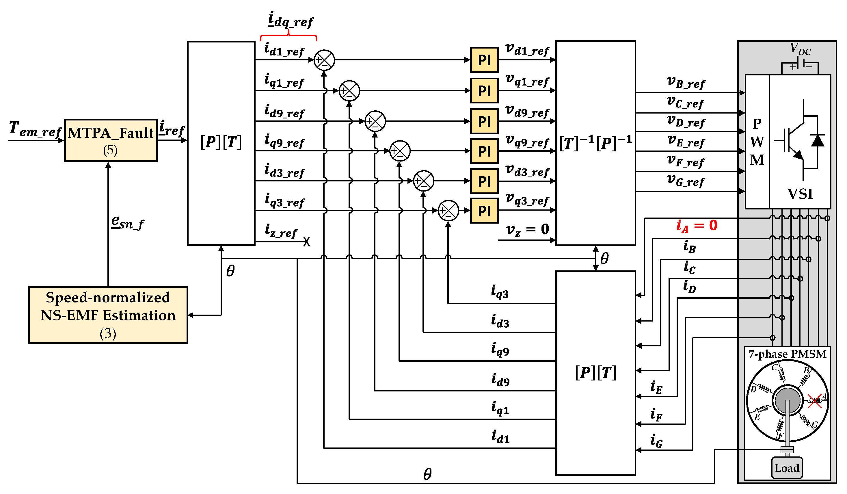
4.2. Proposed Control Scheme for Faulty Mode

The proposed control scheme for faulty mode described in Figure 2 is based on the conventional RFOC scheme, an Adaline, and ECL strategy. New reference currents are determined by using ECL strategy as described in (9), (10) and (13) to generate an average torque Tave equal to Tem_ref. Then, compensating currents are adaptively added to identical waveform phase currents of ECL to eliminate torque ripples. Therefore, phase current waveforms are no longer identical but similar, leading to similar copper losses in the remaining healthy phases. These compensating currents are determined from the compensating torque Tem_com that contains all harmonics or main harmonics of the torque in Table 2. This compensating torque is determined by an Adaline (“Adaline_Fault”) that will be described in the next subsection. The total torque Tem is calculated from measured phase currents and estimated NS-EMFs according to (4).
From Tem_com, compensating currents can be calculated by using Simplified MTPA (SMTPA) that is discussed in the first part of this study as follows:
i _ c o m = T e m _ c o m e _ s n _ f s i m 2 e _ s n _ f s i m
where icom is the 7-dimensional vector of compensating currents in natural frame; e _ s n _ f s i m is the simplified NS-EMF vector created from esn_f in (5) by keeping only 1st, 9th, and 3rd harmonics. Then, currents icom in (14) are transformed into d-q frames idq_com by using (2).
The total reference d-q currents ( i _ d q _ r e f ) for control are combinations of reference d-q currents (idq_ref) from ECL strategy and the compensating currents idq_com as follows:
i _ d q _ r e f = i _ d q _ r e f + i _ d q _ c o m with   i _ d q _ r e f = [ i d 1 _ r e f i q 1 _ r e f i d 9 _ r e f i q 9 _ r e f i d 3 _ r e f i q 3 _ r e f 0 ] T i _ d q _ r e f = [ i d 1 _ r e f i q 1 _ r e f i d 9 _ r e f i q 9 _ r e f i d 3 _ r e f i q 3 _ r e f 0 ] T i _ d q _ c o m = [ i d 1 _ c o m i q 1 _ c o m i d 9 _ c o m i q 9 _ c o m i d 3 _ c o m i q 3 _ c o m 0 ] T

4.3. Structure of Adaline for Faulty Mode

The Adaline for faulty mode (“Adaline_Fault”) can adaptively determine compensating torque Tem_com as well as compensating currents icom, enabling the total torque Tem to properly track reference torque Tem_ref. It is assumed that the total torque T e m generated by using only ECL strategy can be expressed from Table 2 as follows:
T e m * = T a v e * + j = 1 h [ w 2 j 1 cos ( 2 j θ ) + w 2 j sin ( 2 j θ ) ]
where T a v e is the average torque; w 2 j 1 and w 2 j are coefficients representing torque harmonics T 2 j θ , including its amplitude and initial phase angle; and h is the number of torque harmonics.
From (16), for a reference torque Tem_ref, the compensating torque Tem_com is given by:
T e m _ c o m = T e m _ r e f T e m * = { T e m _ r e f T a v e * } j = 1 h [ w 2 j 1 cos ( 2 j θ ) + w 2 j sin ( 2 j θ ) ] = w 0 j = 1 h [ w 2 j 1 cos ( 2 j θ ) + w 2 j sin ( 2 j θ ) ]
where w 0 is the difference between Tem_ref and T a v e . Therefore, the compensating torque Tem_com is represented by (2h + 1) coefficients from w 0 to w 2 h and the electrical position θ.
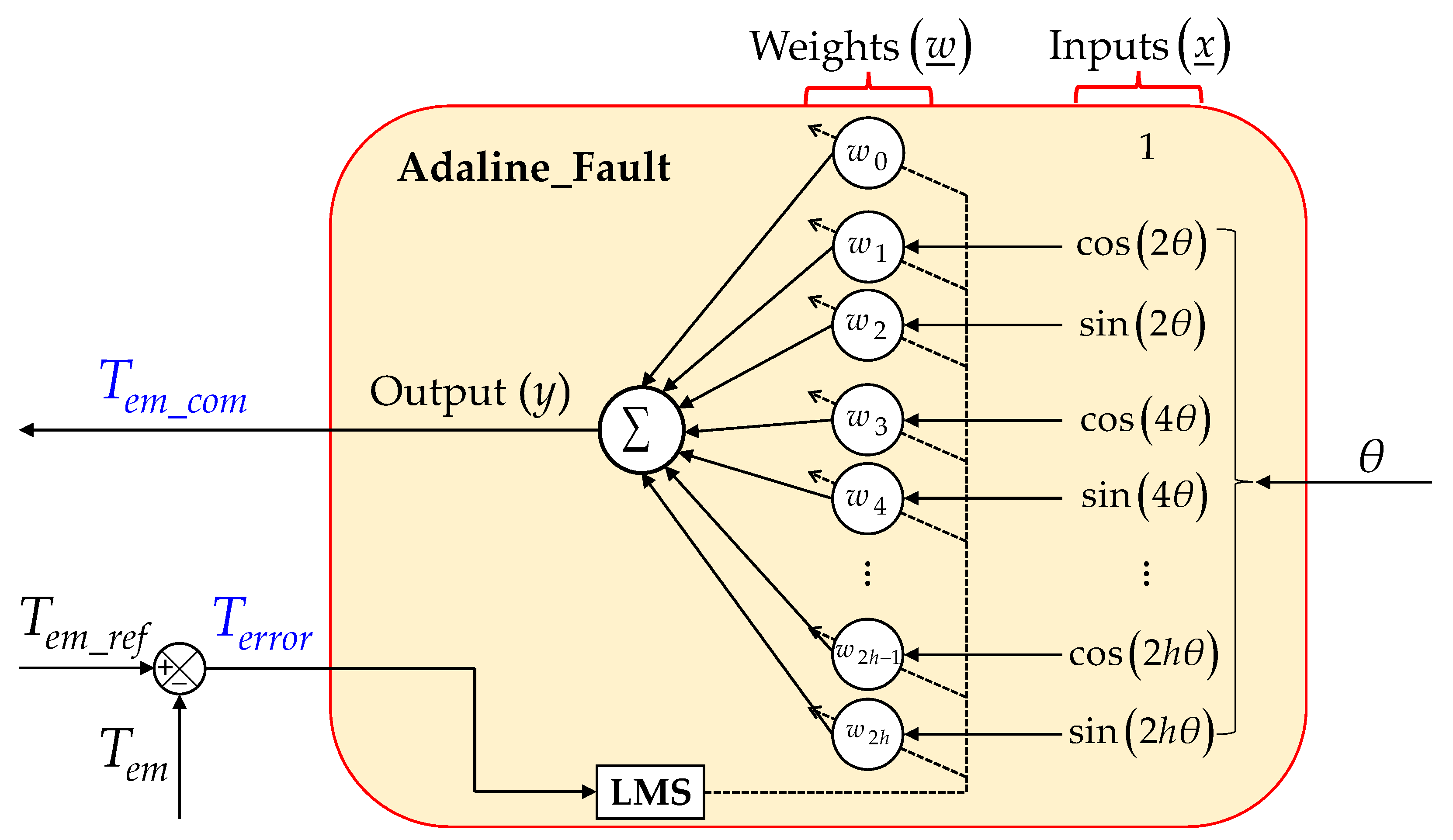
The structure of the Adaline used in Figure 2 is described in Figure 3. The input vector and the weight vector of the Adaline are defined by:
x _ = [ 1 cos ( 2 θ ) sin ( 2 θ ) cos ( 4 θ ) sin ( 4 θ ) cos ( 2 h θ ) sin ( 2 h θ ) ] T
w _ = [ w 0 w 1 w 2 w 3 w 4 w 2 h 1 w 2 h ] T
where wj is a weight corresponding to coefficient w j of the compensating torque Tem_com in (17) with j = { 0 , 1 , 2 , , 2 h } .
The output of the Adaline is the weighted sum of the inputs as follows:
y = w _ T x _ = w 0 + j = 1 h [ w 2 j 1 cos ( 2 j θ ) + w 2 j sin ( 2 j θ ) ]
The Adaline weights are updated by the least mean square (LMS) rule at each sampled time k as:
w _ ( k + 1 ) = w _ ( k ) + η [ T e m _ r e f T e m ( k ) ] x _ ( k ) = w _ ( k ) + η T e r r o r ( k ) x _ ( k )
where η is the learning rate; Terror is the error between reference torque Tem_ref and the total torque Tem; and Tem is calculated from measured phase currents and estimated NS-EMFs in (4).
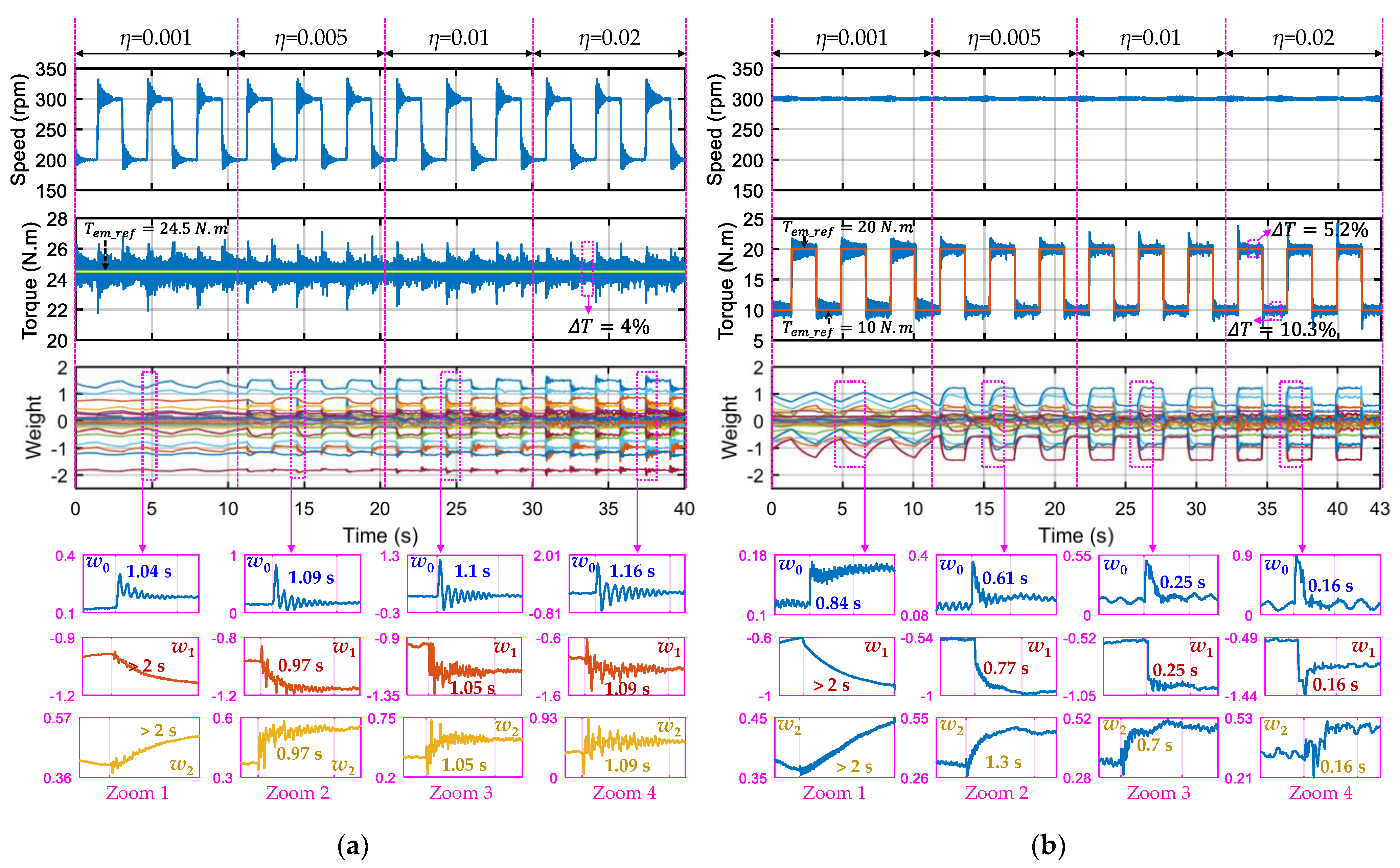
The learning rate η is within 0 and 1 to guarantee the system stability [31]. Its value mainly depends on the sample time of calculations, and characteristics of the desired signal (Tem_com) such as amplitudes and phases of harmonic components. An increase in η possibly results in faster convergence but divergence may appear. On each iteration, the Adaline weights are updated to converge to the coefficients of the compensating torque in (17). Weight convergence is obtained after a given number of iterations as:
{ w 0 ( k ) k w 0 * w j ( k ) k w j *   then y ( k ) k T e m _ c o m and { T e r r o r ( k ) k 0 T e m ( k ) k T e m _ r e f
where w 0 and w j with j = { 1 , 2 , , 2 h } are the coefficients of Tem_com as described in (17).
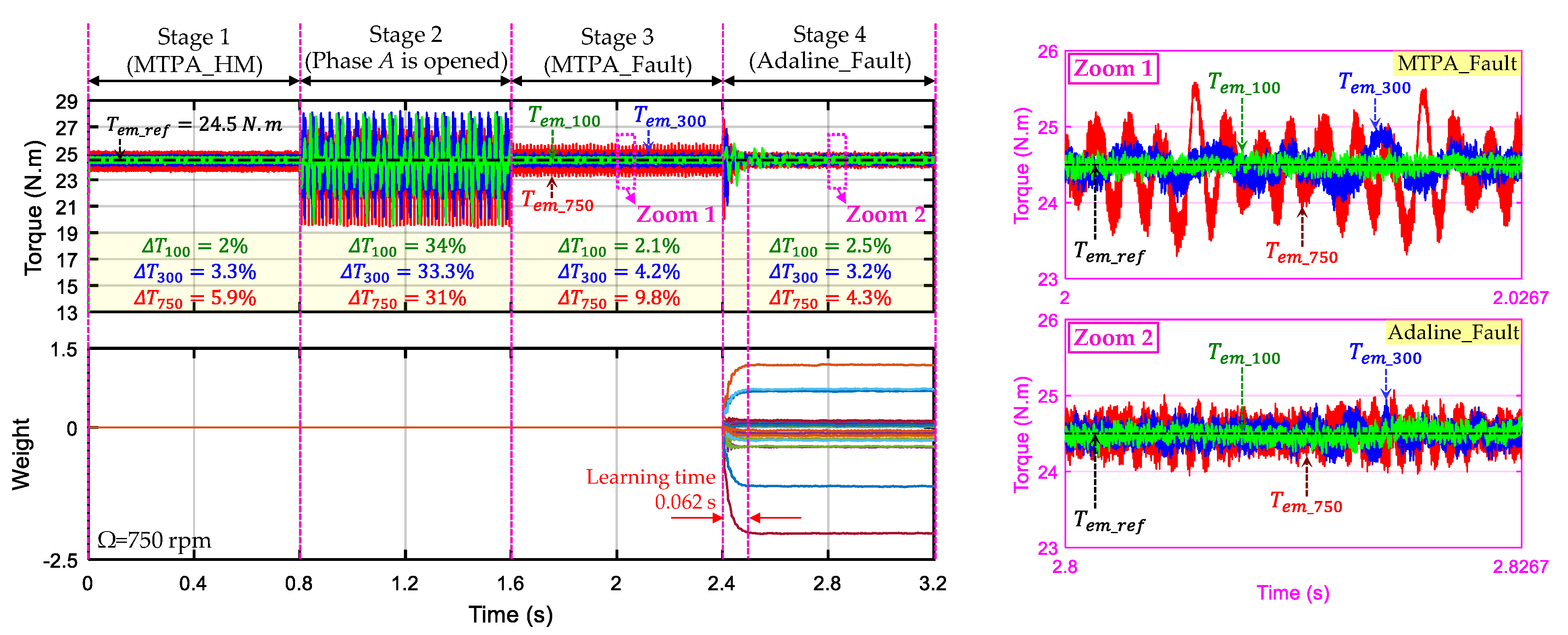
Finally, Terror is theoretically nullified, and the total torque Tem well tracks the reference torque Tem_ref. The proposed Adaline-based control scheme using ECL strategy can guarantee smooth torques in faulty mode regardless of multi-harmonics existing in NS-EMFs and impacts of the mechanical load.
Compared with PIR, the Adaline is simpler because only the learning rate must be properly chosen while other parameters are automatically updated. The knowledge of torque harmonic rank and rotor position is used to optimize the Adaline training. The inputs of Adaline_Fault contain only harmonics of the torque which are caused by the interaction of the six remaining phase currents with the NS-EMF harmonics. The task of the Adaline is relatively light because only existing torque harmonics can induce modifications of the corresponding Adaline weights. In addition, the number of harmonics as well as the number of weights in this fault-tolerant scheme can be reduced to simplify calculations if high torque quality is still guaranteed. If a harmonic of the torque ripples has very small amplitudes compared with the other harmonics and the average torque Tave, this harmonic can be neglected in the Adaline inputs. Practically, a S-function builder block in MATLAB/Simulink can be used to implement the Adaline.

5. Numerical and Experimental Results

5.1. Experimental Seven-Phase Test Bench Description

As part I of this study (healthy mode), the proposed control scheme for faulty mode is tested on the same experimental test bench (see Figure 4 and Table 3). Seven legs of a 12-leg IGBT VSI supply the seven-phase PMSM. A DC-bus voltage (200 V) used to supply the VSI is connected in parallel to a programmable resistive load to protect the DC source. Switching signals for IGBTs are created by the two-level carrier-based PWM strategy. The PWM signal has a frequency of 10 kHz. MATLAB/Simulink is used to program the algorithm and a S-function builder block in Simulink is used to design Adaline_Fault.
A dSPACE 1005 processor is used to execute the program. I/O boards of dSPACE are used to send and receive signals (e.g., send switching signals to VSI, receive the rotor position from an encoder, and receive phase current signals from current sensors). Especially, an open-circuit fault in a phase is set up on the control interface with a signal sent to VSI through a box. Thereafter, two IGBTs of the corresponding phase of the VSI are simultaneously opened, hence, this phase is disconnected from the power supply. An industrial 3-phase PMSM (a load machine) is mechanically connected to the seven-phase PMSM to independently adjust the rotating speed.
The axial flux seven-phase PMSM is composed of one stator and two permanent magnet rotors with electrical parameters described in Table 3. An experimental speed-normalized NS-EMF of one phase and its harmonic spectrum with THD = 38% are shown in Figure 4. The 1st harmonic accounts for the highest proportion (100%), followed by the 3rd harmonic (32.3% of 1st), and the 9th harmonic (12.5% of 1st). Moreover, the NS-EMF consists of other harmonics with lower proportions.

5.2. Numerical Results

In this study, numerical results are obtained from MATLAB Simulink. As assumed in Section 2, six back-EMF harmonics (1st, 13th) in FM1, (9th, 19th) in FM2, and (3rd, 11th) in FM3 with their proportions described in Figure 4 are considered for simulations. To make comparisons between the conventional RFOC scheme using MTPA_Fault and the proposed control scheme using Adaline_Fault and ECL strategy, four operating stages at different rotating speeds are used. The reference torque Tem_ref is reduced from 33.5 N.m (rated torque) in healthy mode to 24.5 N.m in faulty mode to respect the rated RMS current (5.1 A), avoiding the overheating of machine windings. The four operating stages are described as follows:
  • Stage 1: The conventional RFOC scheme with MTPA strategy is used in healthy condition (“MTPA_HM”) as explicitly described in the first part of this study;
  • Stage 2: Phase A is opened without any reconfigurations;
  • Stage 3: The RFOC scheme is preserved but MTPA_Fault is applied (Figure 1);
  • Stage 4: The proposed control scheme using Adaline_Fault and ECL strategy (Figure 2), briefly called Adaline_Fault, is applied. Eleven even harmonics (h = 11) of torque ripples are used to generate compensating torque Tem_com, leading to 23 weights (2h + 1).
The evaluation of torque quality with torque ripple ∆T can be calculated as:
Δ T = m a x ( T e m ) m i n ( T e m ) T a v e 100 %
where max(Tem) and min(Tem) are maximum and minimum values of the electromagnetic torque Tem, respectively; and Tave is the average value of Tem.
Figure 5 presents the torque performance in the four operating states at 100 rpm, 300 rpm, and 750 rpm (rated speed). The RFOC scheme using MTPA_HM in stage 1 (healthy mode) has a torque ripple within 2% (100 rpm) and 5.9% (750 rpm). When phase A is open-circuited, the torque ripple becomes higher than 30%. Therefore, the RFOC using MTPA_Fault and the proposed scheme using Adaline_Fault are then applied. At low speed (100 rpm), both schemes have low torque ripples (only 2.1% for MTPA_Fault and 2.5% for Adaline_Fault). However, the torque ripple with MTPA_Fault increases to 9.8% at 750 rpm (see stage 3 and zoom 1). Meanwhile, the torque ripple with Adaline_Fault slightly increases to 4.3% at 750 rpm (see stage 4 and zoom 2). A learning rate η of 0.0003 is used to update 23 weights of Adaline_Fault, leading to a learning time of 0.062 s. With adaptivity, the proposed scheme has higher torque quality compared with the conventional RFOC scheme with MTPA_Fault. The summary of numerical torque ripples in stages 3 and 4 is described in Table 4.
Figure 6a presents the learning process within 0.062 s at 750 rpm to eliminate Terror, the difference between Tem_ref and Tem. When the Adaline output y converges to the compensating torque Tem_com, Terror is minimized to reduce the torque ripple from 9.8% to 4.3%. Torques generated by the three fictitious machines in stages 3 and 4 are presented in Figure 6b. Notably, torque harmonics in FM1, FM2, and FM3 eliminate each other in both stages. Torques with MTPA_Fault have more harmonic components than those of Adaline_Fault. The proposed explanation for this difference is that MTPA_Fault is a compensation with additions of harmonics to different d-q frames by using all harmonics of NS-EMFs e _ s n _ f in (5). With Adaline_Fault, the compensation is directly calculated at the level of torque with its harmonic components. In addition, as Adaline_fault is online-trained, reference currents are adaptively generated to eliminate torque ripples.
In Figure 7a, the maximum peak voltage reference at 300 rpm with Adaline_Fault (88 V) is lower than that of MTPA_Fault (94 V), leading to a higher speed range. These signals almost reach the experimental phase voltage limit (a half of DC-bus voltage VDC/2 = 100 V). Therefore, numerical voltage references and phase currents at 300 rpm are shown to compare with experimental results. Figure 7b presents phase currents (response signals) with the RFOC scheme using MTPA_Fault and the proposed scheme using Adaline_Fault. Notably, Adaline_Fault has a lower maximum peak current (8.7 A) compared with MTPA_Fault (10 A).
In addition, Adaline_Fault results in phase currents with lower amplitudes of high-order (≥5) harmonic components as described in Figure 8 for phase-B current. Therefore, iron and magnet losses with the proposed scheme using Adaline_Fault can be lower than those of the RFOC scheme using MTPA_Fault [32,33].
Table 5 describes copper losses in the remaining healthy phases and the total copper losses in stages 3 and 4. Per unit (pu) is used to evaluate the changes in copper losses of faulty mode compared with healthy mode for the same reference torque. Notably, with MTPA_Fault, copper losses are significantly different in the remaining healthy phases (from 1.17 to 1.89 pu). Meanwhile, copper losses are similarly distributed in the remaining phases with the proposed Adaline-based scheme (from 1.60 to 1.71 pu), avoiding the overheating of phase windings. However, as expected, the total copper loss of the proposed scheme using Adaline_Fault (1.41 pu) is 14.6% higher than that of MTPA_Fault (1.23 pu).
Finally, from the numerical results, compared with the conventional RFOC scheme using MTPA_Fault, the proposed control scheme using Adaline_Fault and ECL strategy has better torque quality, a lower maximum peak voltage reference, a lower maximum peak phase current, and similarly distributed copper losses in the remaining healthy phases. In addition, Adaline_Fault results in phase currents with lower amplitudes of high-order (≥5) harmonic components, leading to lower iron and magnet losses. These numerical (simulation) results will be compared with experimental results in the next subsection to validate the mathematical model and the proposed control scheme in this study.

5.3. Experimental Results

The star connection and the classical PWM strategy limit the voltage of each machine phase to a half of the DC-bus supply (VDC/2 = 100 V). Therefore, from the numerical voltage references in Figure 7a, the rotating speed of the drive in experiments for faulty mode is limited to 300 rpm instead of the rated speed (750 rpm). Higher speeds could make the effectiveness of the proposed Adaline-based scheme more significant as presented in the numerical section (see Figure 5 and Table 4).
Figure 9 presents experimental torques in the four operating states at 100 rpm and 300 rpm. The RFOC scheme using MTPA_HM in stage 1 (healthy condition) has a torque ripple within 3.7% (at 100 rpm) and 7.2% (at 300 rpm). When phase A is opened, the torque ripple becomes higher than 46%. Therefore, the RFOC scheme using MTPA_Fault and the proposed scheme using Adaline_Fault and ECL strategy are then applied. At 100 rpm, Adaline_Fault has a much lower torque ripple (only 3.5%) than MTPA_Fault does (16.1%). At higher speed (300 rpm), the torque ripple with MTPA_Fault dramatically increases to 30.3% while the torque ripple with Adaline_Fault remains low at 4%.
The summary of experimental torque ripples in stages 3 and 4 are described in Table 4 to compare with the numerical results. In general, the numerical and experimental torque ripples are in good accordance. Owing to more than six harmonics in NS-EMFs (see Figure 4) of the tested machine, the experimental torque ripples are usually higher than those of simulations (only six harmonics are considered). The effectiveness of the proposed scheme using Adaline_Fault and ECL strategy is more impressive in experiments with much lower torque ripples. Indeed, the control scheme using MTPA_Fault can properly work in simulations with low torque ripples (4.2% at 300 rpm) due to a small sample time (3 µs). High torque ripples can be seen in experiments (30.3%) due to a longer sample time (350 µs). In contrast, with adaptivity, the proposed control scheme using Adaline_Fault and ECL strategy has much higher torque quality (torque ripples of less than 4% at 300 rpm in both simulations and experiments).
As numerical results, eleven even harmonics of the torque (23 weights) are adaptively used to eliminate torque ripples in experiments. Compared with simulations, the higher sample time in experiments leads to a higher learning rate η (0.01) for weight updating. Thus, experimental tests have longer learning time (0.2 s at 100 rpm and 0.29 s at 300 rpm) compared with that of simulations (0.062 s at 750 rpm, see Figure 5 and Figure 6).
Figure 10a presents the learning process within 0.29 s at 300 rpm to eliminate Terror. It is noted that the main harmonic of torque ripples in stage 3 is T2θ due to 2 peaks in one electrical period. When y converges to Tem_com, Terror is almost eliminated, making the torque ripple decrease from 30.3% to 4%. Torques generated by the three fictitious machines are presented in Figure 10b. In general, TFM1, TFM3, and TFM3 compensate each other. As numerical results (see Figure 6), torques with the proposed Adaline-based scheme contain less harmonics than those of the RFOC scheme using MTPA_Fault do.
The current control performance of q-axis currents at 300 rpm is described in Figure 11. It is noted that reference q-axis currents with MTPA_Fault have more high-order harmonic components than those of Adaline_Fault. Therefore, the experimental control performance with Adaline_Fault is better than that of MTPA_Fault, especially the control of q3- and q9-axis currents.
The experimental maximum peak voltage reference of phase B is in good accordance with the numerical results in Figure 7a, with 93 V for MTPA_Fault and 89 V for Adaline_Fault, leading to a higher speed range. Measured phase currents with MTPA_Fault and Adaline_Fault are described in Figure 12a. As numerical results, Adaline_Fault has a lower experimental maximum peak current (8.5 A) compared with MTPA_Fault (9.5 A). Adaline_Fault results in lower iron and magnet losses [32,33] thanks to lower amplitudes of high-order (≥5) harmonic components of phase currents (see Figure 12b for phase-B current). Experimental copper losses in the remaining healthy phases and the total copper losses in stages 3 and 4 are described in Table 5. As numerical results, experimental copper losses are similarly distributed in the remaining healthy phases with Adaline_Fault (from 1.51 to 1.79 pu). With MTPA_Fault, copper losses in the remaining healthy phases are significantly different (from 1.21 to 1.82 pu). However, the total copper loss of Adaline_Fault (1.38 pu) is 13.1% higher than that of MTPA_Fault (1.22 pu).
To sum up, experimental values of torque, voltage, current, and copper losses are in good accordance their corresponding numerical values presented in the previous subsection, validating the mathematical model and the proposed control scheme.
The dynamic performance of the proposed scheme using Adaline_Fault and ECL strategy in response to speed and torque variations is presented in Figure 13. These variations are arbitrary and have not yet been learned to test the robustness of the Adaline as well as the proposed control scheme. In addition, four values of learning rate η (0.001, 0.005, 0.01, and 0.02) are used to test Adaline convergence. Weights w0, w1, and w2 related to the main harmonics of torque ripples (T2θ) are zoomed in. The rotating speed variations between 200 rpm and 300 rpm have effects on torque quality as shown in Figure 13a with torque overshoots in transient states, especially with small values of learning rate. In steady states, the torque ripple is about 4%. When the learning rate increases to 0.02, the overshoots slightly decrease. Thus, weight variations can reduce the effect of the speed variation on torque. However, an increase in learning rate results in more oscillations of weights, leading to slightly longer learning time. When the reference torque varies between 10 N.m and 20 N.m at 300 rpm as shown in Figure 13b, the torque ripple increases from 5.2% to 10.3%. However, the torque quality is guaranteed because this ripple increase is due to the decrease in the average torque. Adaline weights are updated in each torque variation and remain almost constant at steady state. An increase in learning rate results in shorter learning time but higher overshoots appear.

6. Conclusions

This part of the study has proposed a control scheme to adaptively improve the quality of NS-EMF multiphase drives with an open-circuit fault. The proposed scheme has been validated on a seven-phase PMSM with a high THD of NS-EMFs. The numerical and experimental results have been in good accordance to prove the effectiveness of the proposed scheme. Specifically, smooth torque has been obtained with the proposed scheme (an experimental torque ripple of 4% compared with 30.3% of the conventional MTPA strategy). Similar copper losses with the proposed ECL strategy have been distributed in the remaining healthy phases with experimental copper losses of phases between 1.51 to 1.79 pu. Meanwhile, the copper losses of phases with the conventional MTPA strategy significantly vary from 1.21 to 1.82 pu but the total copper loss is 13.1% lower than the proposed ECL strategy. Notably, phase currents in the remaining healthy phases with the proposed Adaline-based scheme using ECL strategy contain less high-frequency harmonics compared with the conventional MTPA strategy, leading to lower iron and magnet losses.
The proposed Adaline utilizing the knowledge of the drives is practical because of its simplicity with only one parameter (learning rate) to be properly chosen. Although the proposed scheme using Adaline has been presented for a single-phase open-circuit fault, it can be adapted for more opened phases. Finally, by using the Adaline-based schemes proposed in parts I and II of this study, any electric machine with an arbitrary harmonic spectrum and phase number can be controlled with high-quality vector control in healthy and faulty modes.

Supplementary Materials

The following supporting information can be downloaded at: https://www.mdpi.com/article/10.3390/en15010249/s1, Video S1: Video Demonstration_video_FM_all_operations.

Author Contributions

Methodology, software, validation, writing—original draft, D.T.V.; writing—review and editing, N.K.N., E.S. and H.W.; and supervision, N.K.N. and E.S. All authors have read and agreed to the published version of the manuscript.

Funding

This research was funded by CE2I project. CE2I is co-financed by the European Union with the financial support of European Regional Development Fund (ERDF), French State, and the French Region of Hauts-de-France.

Institutional Review Board Statement

Not applicable.

Informed Consent Statement

Not applicable.

Conflicts of Interest

The authors declare no conflict of interest.

References

  1. Levi, E. Multiphase Electric Machines for Variable-Speed Applications. IEEE Trans. Ind. Electron. 2008, 55, 1893–1909. [Google Scholar] [CrossRef]
  2. Barrero, F.; Duran, M.J. Recent Advances in the Design, Modeling, and Control of Multiphase Machines Part I. IEEE Trans. Ind. Electron. 2016, 63, 449–458. [Google Scholar] [CrossRef]
  3. Duran, M.J.; Barrero, F. Recent Advances in the Design, Modeling, and Control of Multiphase Machines Part II. IEEE Trans. Ind. Electron. 2016, 63, 459–468. [Google Scholar] [CrossRef]
  4. Semail, E.; Kestelyn, X.; Bouscayrol, A. Right harmonic spectrum for the back-electromotive force of an n-phase synchronous motor. In Proceedings of the 39th IEEE Industry Applications Conference, Seattle, WA, USA, 3–7 October 2004; pp. 71–78. [Google Scholar]
  5. Slunjski, M.; Stiscia, O.; Jones, M.; Levi, E. General Torque Enhancement Approach for a Nine-Phase Surface PMSM With Built-In Fault Tolerance. IEEE Trans. Ind. Electron. 2021, 68, 6412–6423. [Google Scholar] [CrossRef]
  6. You, Y.-M. Optimal Design of PMSM Based on Automated Finite Element Analysis and Metamodeling. Energies 2019, 12, 4673. [Google Scholar] [CrossRef] [Green Version]
  7. Wang, L.; Zhu, Z.Q.; Bin, H.; Gong, L.M. Current Harmonics Suppression Strategy for PMSM with Non-Sinusoidal Back-EMF Based on Adaptive Linear Neuron Method. IEEE Trans. Ind. Electron. 2020, 67, 9164–9173. [Google Scholar] [CrossRef]
  8. Li, X.; Jiang, G.; Chen, W.; Shi, T.; Zhang, G.; Geng, Q. Commutation Torque Ripple Suppression Strategy of Brushless DC Motor Considering Back Electromotive Force Variation. Energies 2019, 12, 1932. [Google Scholar] [CrossRef] [Green Version]
  9. Dwari, S.; Parsa, L. An Optimal Control Technique for Multiphase PM Machines Under Open-Circuit Faults. IEEE Trans. Ind. Electron. 2008, 55, 1988–1995. [Google Scholar] [CrossRef]
  10. Kestelyn, X.; Semail, E. A Vectorial Approach for Generation of Optimal Current References for Multiphase Permanent-Magnet Synchronous Machines in Real Time. IEEE Trans. Ind. Electron. 2011, 58, 5057–5065. [Google Scholar] [CrossRef] [Green Version]
  11. Flieller, D.; Nguyen, N.K.; Wira, P.; Sturtzer, G.; Abdeslam, D.O.; Mercklé, J. A Self-Learning Solution for Torque Ripple Reduction for Nonsinusoidal Permanent-Magnet Motor Drives Based on Artificial Neural Networks. IEEE Trans. Ind. Electron. 2014, 61, 655–666. [Google Scholar] [CrossRef] [Green Version]
  12. Vu, D.T.; Nguyen, N.K.; Semail, E.; Wu, H. Adaline-Based Control Schemes for Non-Sinusoidal Multiphase Drives-Part I: Torque Optimization for Healthy Mode. Energies 2021, 14, 8302. [Google Scholar] [CrossRef]
  13. Zhao, J.; Gao, X.; Li, B.; Liu, X.; Guan, X. Open-Phase Fault Tolerance Techniques of Five-Phase Dual-Rotor Permanent Magnet Synchronous Motor. Energies 2015, 8, 12810–12838. [Google Scholar] [CrossRef]
  14. Akay, A.; Lefley, P. Torque Ripple Reduction Method in a Multiphase PM Machine for No-Fault and Open-Circuit Fault-Tolerant Conditions. Energies 2021, 14, 2615. [Google Scholar] [CrossRef]
  15. Jen-Ren, F.; Lipo, T.A. Disturbance-free operation of a multiphase current-regulated motor drive with an opened phase. IEEE Trans. Ind. Appl. 1994, 30, 1267–1274. [Google Scholar] [CrossRef]
  16. Toliyat, H.A. Analysis and simulation of five-phase variable-speed induction motor drives under asymmetrical connections. IEEE Trans. Power Electron. 1998, 13, 748–756. [Google Scholar] [CrossRef]
  17. Sui, Y.; Zheng, P.; Yin, Z.; Wang, M.; Wang, C. Open-Circuit Fault-Tolerant Control of Five-Phase PM Machine Based on Reconfiguring Maximum Round Magnetomotive Force. IEEE Trans. Ind. Electron. 2019, 66, 48–59. [Google Scholar] [CrossRef]
  18. Akay, A.; Lefley, P. Open-Circuit Fault-Tolerant Control of Multi-Phase PM Machines by Compensating the d-q Axes Currents. Energies 2021, 14, 192. [Google Scholar] [CrossRef]
  19. Iftikhar, M.H.; Park, B.-G.; Kim, J.-W. Design and Analysis of a Five-Phase Permanent-Magnet Synchronous Motor for Fault-Tolerant Drive. Energies 2021, 14, 514. [Google Scholar] [CrossRef]
  20. Locment, F.; Semail, E.; Kestelyn, X. Vectorial Approach-Based Control of a Seven-Phase Axial Flux Machine Designed for Fault Operation. IEEE Trans. Ind. Electron. 2008, 55, 3682–3691. [Google Scholar] [CrossRef] [Green Version]
  21. Vu, D.T.; Nguyen, N.K.; Semail, E.; Moraes, T.J.d.S. Control strategies for non-sinusoidal multiphase PMSM drives in faulty modes under constraints on copper losses and peak phase voltage. In IET Electric Power Applications; Institution of Engineering and Technology: London, UK, 2019; Volume 13, pp. 1743–1752. [Google Scholar]
  22. Tian, B.; Mirzaeva, G.; An, Q.; Sun, L.; Semenov, D. Fault-Tolerant Control of a Five-Phase Permanent Magnet Synchronous Motor for Industry Applications. IEEE Trans. Ind. Appl. 2018, 54, 3943–3952. [Google Scholar] [CrossRef]
  23. Zhou, H.; Zhou, C.; Tao, W.; Wang, J.; Liu, G. Virtual-Stator-Flux-Based Direct Torque Control of Five-Phase Fault-Tolerant Permanent-Magnet Motor With Open-Circuit Fault. IEEE Trans. Power Electron. 2020, 35, 5007–5017. [Google Scholar] [CrossRef]
  24. Liu, G.; Lin, Z.; Zhao, W.; Chen, Q.; Xu, G. Third Harmonic Current Injection in Fault-Tolerant Five-Phase Permanent-Magnet Motor Drive. IEEE Trans. Power Electron. 2018, 33, 6970–6979. [Google Scholar] [CrossRef]
  25. Xiong, C.; Xu, H.; Guan, T.; Zhou, P. Fault-tolerant FOC for five-phase SPMSM with non-sinusoidal back EMF. In IET Electric Power Applications; Institution of Engineering and Technology: London, UK, 2019; Volume 13, pp. 1734–1742. [Google Scholar]
  26. Xiong, C.; Guan, T.; Zhou, P.; Xu, H. A Fault-Tolerant FOC Strategy for Five-Phase SPMSM With Minimum Torque Ripples in the Full Torque Operation Range Under Double-Phase Open-Circuit Fault. IEEE Trans. Ind. Electron. 2020, 67, 9059–9072. [Google Scholar] [CrossRef]
  27. Vu, D.T.; Nguyen, N.K.; Semail, E. Fault-tolerant Control for Non-sinusoidal Multiphase Drives with Minimum Torque Ripple. IEEE Trans. Power Electron. 2021, 37, 1. [Google Scholar] [CrossRef]
  28. Guzman, H.; Duran, M.J.; Barrero, F.; Zarri, L.; Bogado, B.; Prieto, I.G.; Arahal, M.R. Comparative Study of Predictive and Resonant Controllers in Fault-Tolerant Five-Phase Induction Motor Drives. IEEE Trans. Ind. Electron. 2016, 63, 606–617. [Google Scholar] [CrossRef]
  29. Kong, W.; Kang, M.; Li, D.; Qu, R.; Jiang, D.; Gan, C. Investigation of Spatial Harmonic Magnetic Field Coupling Effect on Torque Ripple for Multiphase Induction Motor Under Open Fault Condition. IEEE Trans. Power Electron. 2018, 33, 6060–6071. [Google Scholar] [CrossRef]
  30. Qu, J.; Zhang, C.; Jatskevich, J.; Zhanga, S. Deadbeat Harmonic Current Control of Permanent Magnet Synchronous Machine Drives for Torque Ripple Reduction. IEEE J. Emerg. Sel. Top. Power Electron. 2021, 1. [Google Scholar] [CrossRef]
  31. Widrow, B.; Walach, E. Adaptive Inverse Control; Prentice-Hall: Hoboken, NJ, USA, 1996. [Google Scholar] [CrossRef]
  32. Jia, H.; Yang, J.; Deng, R.; Wang, Y. Loss Investigation for Multiphase Induction Machine under Open-Circuit Fault Using Field–Circuit Coupling Finite Element Method. Energies 2021, 14, 5686. [Google Scholar] [CrossRef]
  33. Aslan, B.; Semail, E.; Legranger, J. General Analytical Model of Magnet Average Eddy-Current Volume Losses for Comparison of Multiphase PM Machines With Concentrated Winding. IEEE Trans. Energy Convers. 2014, 29, 72–83. [Google Scholar] [CrossRef] [Green Version]
Figure 1. Torque control with the conventional RFOC scheme using MTPA_Fault for a seven-phase PMSM when phase A is opened.
Energies 15 00249 g001
Figure 2. Torque control with the proposed control scheme using Adaline_Fault and ECL strategy for a seven-phase PMSM when phase A is opened.
Energies 15 00249 g002
Figure 3. Adaline structure with single layer for the proposed control scheme of a seven-phase PMSM in faulty condition.
Energies 15 00249 g003
Figure 4. Experimental test bench and the multi-harmonic NS-EMF spectrum of the seven-phase PMSM to validate the proposed control scheme using Adaline_Fault and ECL strategy in faulty mode.
Energies 15 00249 g004
Figure 5. (Numerical result) The torque at 100 rpm (green), 300 rpm (blue), and 750 (red) rpm in the four operating stages, and 23 Adaline weights at 750 rpm with learning rate η = 0.0003 in stage 4.
Energies 15 00249 g005
Figure 6. (Numerical result) Switch from stage 3 to 4 when phase A is opened at 750 rpm: (a) elimination of Terror with the proposed Adaline-based scheme (η = 0.0003) in stage 4; and (b) torques of three fictitious machines TFM1, TFM2, and TFM3 in one electrical period.
Energies 15 00249 g006
Figure 7. (Numerical result) Voltages and currents at 300 rpm in stages 3 and 4 when phase A is opened: (a) phase voltage references; and (b) phase currents.
Energies 15 00249 g007
Figure 8. (Numerical result) Harmonic spectrum of phase-B current with the RFOC scheme using MTPA_Fault (Stage 3), and the proposed scheme using Adaline_Fault (Stage 4), when phase A is opened at 300 rpm.
Energies 15 00249 g008
Figure 9. (Experimental result) The torque performance and 23 Adaline weights in the four operating stages in which stage 4 applies the proposed scheme using Adaline_Fault (η = 0.01) and ECL strategy: (a) at 100 rpm; and (b) at 300 rpm.
Energies 15 00249 g009
Figure 10. (Experimental result) Switch from stage 3 to 4 when phase A is opened at 300 rpm: (a) elimination of Terror with the proposed Adaline-based scheme (η = 0.01) in stage 4; and (b) torques of fictitious machines (TFM1, TFM2, TFM3) in one electrical period.
Energies 15 00249 g010
Figure 11. (Experimental result) The q-axis current control performance in one electrical period when phase A is opened at 300 rpm with: (a) conventional RFOC scheme using MTPA_Fault in stage 3; and (b) proposed scheme using Adaline_Fault (η = 0.01) and ECL strategy in stage 4.
Energies 15 00249 g011
Figure 12. (Experimental result) Phase current analyses when phase A is opened at 300 rpm: (a) measured phase currents in stages 3 and 4; and (b) harmonic spectrum of phase-B current.
Energies 15 00249 g012
Figure 13. (Experimental result) Dynamic performance of the proposed control scheme using Adaline_Fault and ECL strategy with four values of learning rate η when phase A is opened with: (a) rotating speed variations; and (b) reference torque variations.
Energies 15 00249 g013
Table 1. Fictitious machines, reference frames, and associated harmonics in natural frame of a seven-phase machine (only odd harmonics are considered).
Fictitious MachineReference FrameAssociated Harmonic *
1st fictitious machine (FM1)d1-q11, 13, 15, …, 7k ± 1
2nd fictitious machine (FM2)d9-q95, 9, 19, …, 7k ± 2
3rd fictitious machine (FM3)d3-q33, 11, 17 …, 7k ± 3
Zero-sequence machine (ZM)z7, 21, …, 7k
* With k Ν 0 .
Table 2. Possible harmonic components of torque generated by NS-EMF harmonics and current harmonics of the considered seven-phase machine in faulty mode.
NS-EMF Harmonics1st3rd9th11th13th19th
Current Harmonics
1st2θ2θ, 4θ8θ, 10θ10θ, 12θ12θ, 14θ18θ, 20θ
3rd2θ, 4θ6θ6θ, 12θ8θ, 14θ10θ, 16θ16θ, 22θ
Table 3. Electrical parameters of the experimental test bench (the seven-phase PMSM drive).
ParameterUnitValue
Stator resistance RΩ1.4
Self-inductance LmH14.7
Mutual inductance M1mH3.5
Mutual inductance M2mH−0.9
Mutual inductance M3mH−6.1
The 1st harmonic of speed-normalized NS-EMFs En1V/rad/s1.27
Number of pole pairs p 3
Rated RMS currentA5.1
Rated voltageV120
Rated torqueN.m33.5
Rated powerkW2.5
Rated speedrpm750
PWM frequencykHz10
Maximum DC-bus voltage VDCV200
Table 4. Comparisons between stages 3 (MTPA_Fault) and 4 (Adaline_Fault) in terms of torque ripples at different speeds when phase A is opened.
Speed
Ω (rpm)
T (%)
Stage 3 (MTPA_Fault)Stage 4 (Adaline_Fault)
sim1exp2sim1exp2
1002.116.12.53.5
3004.230.33.24
7509.8-4.3-
1 simulation (numerical) result; 2 experimental result.
Table 5. Comparisons between stage 3 (MTPA_Fault) and stage 4 (Adaline_Fault) at 300 rpm in terms of copper losses when phase A is opened.
PhasePloss (pu) *
Stage 3 (MTPA_Fault)Stage 4 (Adaline_Fault)
sim1exp2sim1exp2
B1.891.821.711.79
C1.371.351.621.54
D1.261.221.651.57
E1.271.221.671.53
F1.171.211.601.51
G1.611.621.621.64
Total1.231.221.411.38
* Per unit based on copper losses in healthy mode to generate the same torque. 1 simulation (numerical) result; 2 experimental result.
Publisher’s Note: MDPI stays neutral with regard to jurisdictional claims in published maps and institutional affiliations.

