Article

Comparison of How Graphite and Shungite Affect Thermal, Mechanical, and Dielectric Properties of Dielectric Elastomer-Based Composites

by
Ewa Olewnik-Kruszkowska
1,*,
Arkadiusz Adamczyk
2,*,
Magdalena Gierszewska
1 and
Sylwia Grabska-Zielińska
1
1
Department of Physical Chemistry and Physicochemistry of Polymers, Faculty of Chemistry, Nicolaus Copernicus University in Toruń, Gagarin 7, 87-100 Torun, Poland
2
Faculty of Mechanical and Electrical Engineering, Polish Naval Academy of the Heroes Westerplatte, Śmidowicza 69, 81-127 Gdynia, Poland
*
Authors to whom correspondence should be addressed.
Energies 2022, 15(1), 152; https://doi.org/10.3390/en15010152
Submission received: 6 December 2021 / Revised: 20 December 2021 / Accepted: 22 December 2021 / Published: 27 December 2021
(This article belongs to the Section D1: Advanced Energy Materials)

Abstract

:
The aim of this work involved comparing the effect graphite and shungite have on the properties of dielectric elastomer-based materials. For this reason, dielectric elastomer–Sylgard (S) was filled with 1, 3, 5, 10, and 15 wt.% of graphite (G) and shungite (Sh). The structure of the obtained materials was studied by means of scanning electron microscopy and atomic force microscopy. The influence of the introduced additives on the thermal stability of the obtained composites was evaluated using thermogravimetry. Moreover, the mechanical properties and the dielectric constant of the elastomer with an addition of graphite and shungite were determined. Obtained results allowed us to establish that the presence of graphite as well as shungite significantly influences mechanical as well as dielectric properties. Additionally, the optimum mass of additives, allowing to increase the dielectric constant without the significant decrease of strain at break, was indicated. In the case of materials containing graphite, regardless of the filler content (1–15 wt.%), the mechanical as well as the dielectric properties are improved, while in the case of composites with an addition of shungite exceeding the 5 wt.% of filler content, a reduced tensile strength was observed.

1. Introduction

Dielectric elastomers, also called electrostrictive polymers, belong to the group of so-called intelligent materials that exhibit particular mechanical properties once affected by an electric current. Dielectric elastomers are characterized by much higher values of generated deformations and forces than most other smart materials, such as magnetic alloys with shape memory or piezoelectric materials. In that respect, their parameters are similar to muscles, hence their colloquial name, “artificial muscles”. Thanks to their electrostrictive deformation capacity, these materials enable the design and construction of elements of executive robots such as robotic manipulators [1].
The basic principle according to which the dielectric elastomers operate mainly involves converting electrical energy into mechanical energy. It should be mentioned that they are characterized by high mechanical strength, hence the wide possibility of their use in various industries. This type of electroactive polymers also displays promising levels of performance in scavenging ambient mechanical energy. Therefore the technology has the potential to be an alternative to electromagnetism-based solutions [2,3]. The application mentioned above can result in a decrease in carbon dioxide emissions and consequently contribute to the achievement of the NetZero effect [4]. It should be stressed, however, that the NetZero effect is a more complex problem encompassing gas emissions not only during the application but also on other planes, such manufacturing, service life, and the possibility of further processing/reuse of the materials.
The continuous technological progress and the increasing amount of demand for new, even better materials, force us to undertake new activities aimed at improving the properties of the above-mentioned materials. For this reason, different additives, as well as fillers, are introduced into the polymer matrix.
The most popular additives that are able to influence the dielectric constant and mechanical properties of dielectric elastomers include: nickel particles [5], iron, copper and ceramic nanoparticles [6,7,8,9], titanium dioxide powder [10], as well as other compounds containing titanium atoms in their structure, such as SrTiO3 [11] and CaCu3Ti4O12 [12]. Other compounds that can be applied as fillers to form materials with an improved dielectric constant are graphite and shungite [13,14,15].
Graphite is a carbonaceous filler, which is natural and a relatively low-cost material. Graphite structure consists of layers in which weak van der Waals forces bond conjugated six-membered aromatic cyclic systems. Different modifications of graphite allow obtaining graphite derivatives. Chemical exfoliation of graphite powder leads to the formation of graphene oxide [16]. An oxidizing agent (sulfuric acid) introduced between graphite interlayers forms a graphite intercalation compound that, when heated, allows for obtaining expanded graphite [17]. Recently, one of the most popular carbonaceous materials–graphene is also manufactured from graphite [18].
Graphite and its derivatives have found wide application, such as the use as an electronically conducting filler applied in preparing polymer composites [19,20,21,22,23,24]. In the work of Torgut et al. [25], a graphite particle filler was introduced into copolymers of 2-hydroxyethyl methacrylate and N-isopropylacrylamide. Wu et al. [26] analyzed dielectric properties of composites based on poly(vinylidene fluoride) with an addition of graphite nanosheet and nickel particles. Dielectric properties of graphite-based epoxy composites and polyurethane–PZT–graphite foam composites were analyzed by Kranauskaite et al. [27] and Tolvanen et al. [28], respectively. Nanocomposites based on high-density polyethylene filled with expanded graphite characterized by enhanced dielectric constant and extremely low dielectric loss were described in the work of Xu et al. [29]. The synergetic effect of Fe2TiO5 and graphite particles introduced into poly(vinylidene fluoride)-based materials was observed by Feng et al. [30].
Another carbonaceous filler used in the present work was shungite. Shungite is a mineral that has recently increased in popularity. Shungite is a microheterogeneous natural mineral complex containing non-crystalline carbon, silicates, a small quantity of metal oxides, and organic additives [31,32]. Originally, shungite was described thanks to the resources obtained near the village of Shunga (Russia). Shungite rocks are classified into five types depending on the carbon content. Some deposits consist of almost pure carbon (up to 98% by weight, so-called type I). The most popular variant of shungite is type III (with a carbon content of 20–35 wt.%) [33,34]. Shungite may differ in structure and properties, depending on the place of origin. Shungite is a hard mineral with a compact structure and black color. Its density, depending on the variety, ranges between 2.04 and 2.25 g/cm3. Due to the fact that shungite contains nanotubes and fullerenes in its structure, this mineral is highly porous. Shungite also exhibits conductive properties and considerable mechanical strength [35,36,37]. Its modulus of elasticity is the highest among all of the carbon materials, including graphite. Taking into account the reactivity of shungite, it can be observed that it is more reactive than coke and, at the same time, more resistant to the oxidation process than graphite. The composites based on ethylene propylene diene with an addition of shungite were synthesized by Barashkova et al. [38]. Shungite was also introduced into nitriloacryl butadien rubber, ethylenepropylene rubber, butyl rubber, isoprene, and fluorine rubbers [39]. Shungite has also found application as an electrically conductive additive in cement composites [40].
It was established that a carbonaceous filler significantly influences mechanical properties, such as elongation and durability. In the work of Żenkiewicz et al. [41], the composites consisting of polylactide, and both graphite and shungite were studied. Based on the obtained results, it was observed that in the case of filler contents of up to 10 wt.%, the changes in mechanical properties were insignificant.
The aim of this work is to analyze the effect of different amounts (between 1 and 15 wt.%) of graphite and shungite on structural, thermal, mechanical, and dielectric properties. Considering the properties of both carbonaceous fillers characterized above, introducing them into PDMS is likely to provide valuable insight into possible applications of the obtained materials. The comparison of changes in the properties mentioned above, caused by either of the fillers, can help determine the desired and effective type and amount of carbonaceous material.

2. Materials and Methods

2.1. Materials

Polydimethylsiloxane (PDMS)- Sylgard 184 from Dow Corning Europe S.A. (Machelen, Belgium) was used as the polymer matrix. Sylgard 184 belongs to a two-component PDMS consisting of component A and component B. The solvent n-hexane was purchased from Chempur (Piekary Śląskie, Poland). Graphite, type 231-955-3 was delivered by POCH SA (Gliwice, Poland). Another filler, shungite, containing 33 wt.% of carbon, was obtained from North of Lake Onega (Karelia, Russia).

2.2. Formation of PDMS-Based Composites

In the first stage, 10 g of component A of Sylgard was dissolved in 40 g of n-hexane. Subsequently, the appropriate amount of carbonaceous filler was introduced into the mixture (the mass of filler constituting 1, 3, 5, 10, and 15 wt.% of mass component A). With the aim to obtain a uniform distribution of graphite and shungite in the polymer matrix, an ultrasound mixer was applied. After 30 min of mixing, the Sylgard B component was added. It should be noted that the weight ratio of component A to component B was 10. After 30 min of mixing, the resulting samples were placed in square, polystyrene Petri dishes and left in a dryer at a temperature of 70 °C for five days.

2.3. Composites Characterization Methods

The morphology of the obtained composites containing carbonaceous filler was analyzed using the Quanta 3D FEG SEM/FIB scanning electron microscope. SE signal detection with a 1.2-nm resolution capability was applied.
The element mapping of the used fillers was studied by using scanning electron microscope (SEM 1430 VP, LEO Electron Microscopy Ltd., Oberkochen, Germany) connected with an energy dispersive X-ray spectrometer (EDX) Quantax 200 (Bruker AXS, Karlsruhe, Germany).
The morphology and structure of the obtained composites was evaluated by means of an atomic force microscope Veeco SPM (Digital Instrument). The size of the scan area was 5 μm × 5 μm. The roughness parameters were square (Rq) and arithmetical mean deviation of the assessed profile (Ra) as well as (Rmax) calculated using Nanoscope software (Veeco Metrology, Inc., Santa Barbara, CA, USA). The definition as well as the equations describing the roughness parameters have been presented in our previous work [42].
The influence of carbonaceous filler on the thermal stability of the obtained composites was analyzed using the SDT 2960 Simultaneous TGA-DTA by TA Instruments. The samples were studied in an air atmosphere in a temperature range between 25 °C and 600 °C with a heating rate of 10 °C/min.
The mechanical properties were carried out in accordance with the PN EN ISO 527-1:2012 and PN EN ISO 527-2:2012 standards: The dimensions of the samples were determined using the ZKM 02-150 microscope.
The dielectric properties of the materials were measured by applying a specially designed laboratory stand. The active elements of the laboratory stand were 4.02 mm thick with copper plate electrodes with a working surface of 50.00 mm in diameter. After determining the dimensions of the electrodes using a digital sensor for absolute measurement with a resolution of 0.01 mm from Mitutoyo and a digital micrometer with a resolution of 0.001 mm from Mahr, they were galvanically connected to the measuring leads in a non-interfering manner.
The measurements of the dielectric properties were carried out with the Dual Display LCR DE-5000 analyzer with an AC voltage of 600 mV and a frequency range of 102 to 105 Hz at room (23 °C) temperature. The capacitance of the device, resulting from placing the tested sample between the electrodes, was measured with an accuracy of 0.01 pF.

3. Results and Discussion

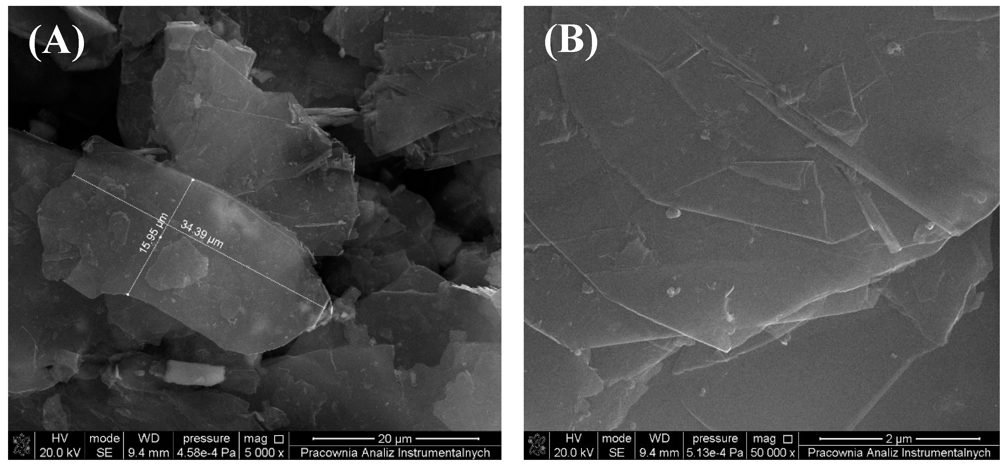
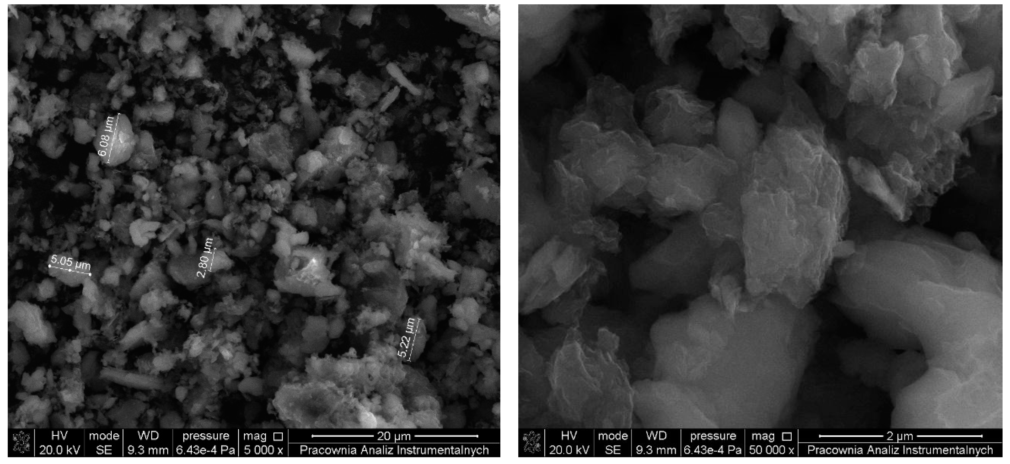
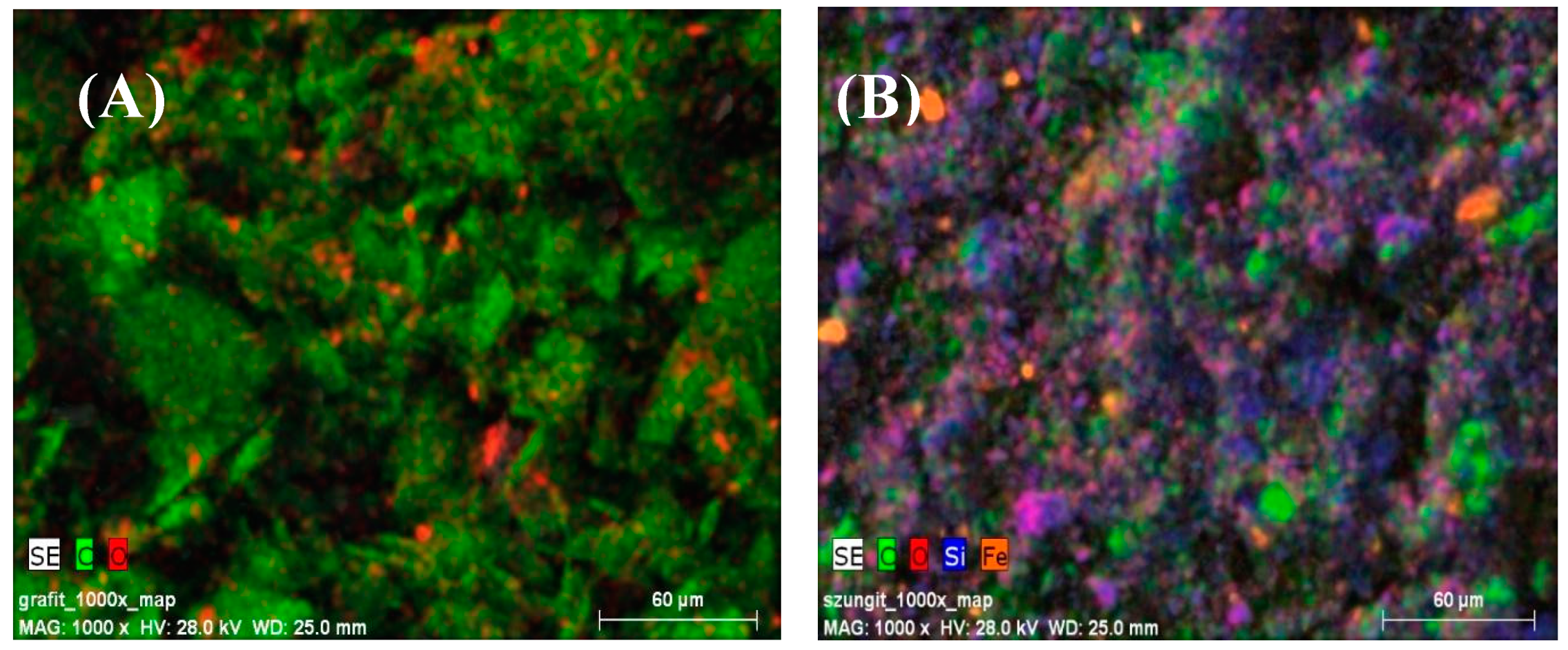
3.1. Morphology and Topography of Carbonaceous Fillers

In the first stage, the morphology of the fillers used in the study and the obtained composites, consisting of PDMS and the carbonaceous additives mentioned above, was analyzed. For this reason, scanning electron microscopy (SEM) was used and the obtained results have been presented in respective figures. In Figure 1A,B the structure of graphite has been depicted. It is well known that graphite is formed of layers connected by weak van der Waals forces [29]. Taking into account the presented images (Figure 1A,B), the layered structure can be clearly observed. According to the literature [17], the thickness of individual flakes is about 50 nm. The structure of graphite was also described by Kranauskaite [27] where similar, typical diameters of graphite have been indicated.
The morphology of shungite is presented in Figure 2A,B.
It can be seen that shungite particles are significantly smaller compared to those observed in graphite. In shungite, contrary to graphite, the difference in size between individual particles is much greater and, according to the literature [43], ranges from 400 to 500 nm. The SEM analysis of shungite was also presented in the work of Diyuk [44] where the grains of separate compounds were observed.
In turn, in Figure 3, mapping images obtained by means of scanning electron microscopy with energy dispersive X-ray analysis (SEM-EDX) have allowed for a comparison of composition of the carbonaceous fillers used in the study.
The analysis of images (Figure 3) in connection with the data presented in Table 1 provides insight into the composition of graphite and shungite. The type of basic, chemical elements and their quantity in the prepared samples were determined by energy dispersive spectroscopy. The composition of graphite is in line with the results obtained by Siburian et al. [45] and Ogbu et al. [46]. Taking into account the presented data, it can clearly be seen that in the case of graphite, the quantity of carbon is more than four times higher in comparison with shungite. In the case of shungite, the chemical elements such as carbon, oxygen, residual amount of ferrum, silicon, as well as compounds based on oxygen and silicon, in particular SiO2, have been detected. The composition of shungite was described also in the work of Obradovic et al. [31].

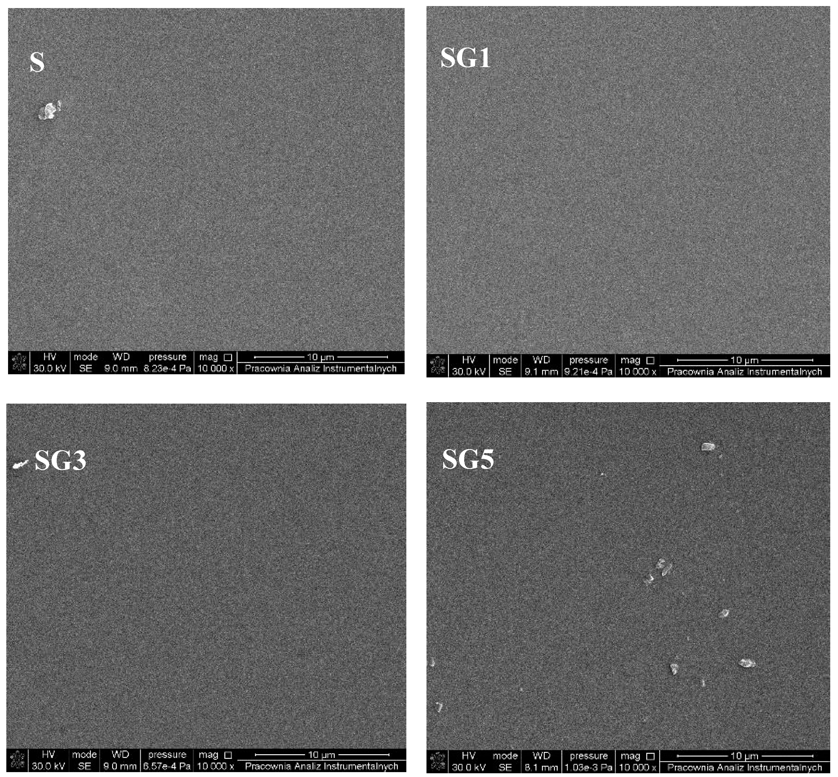
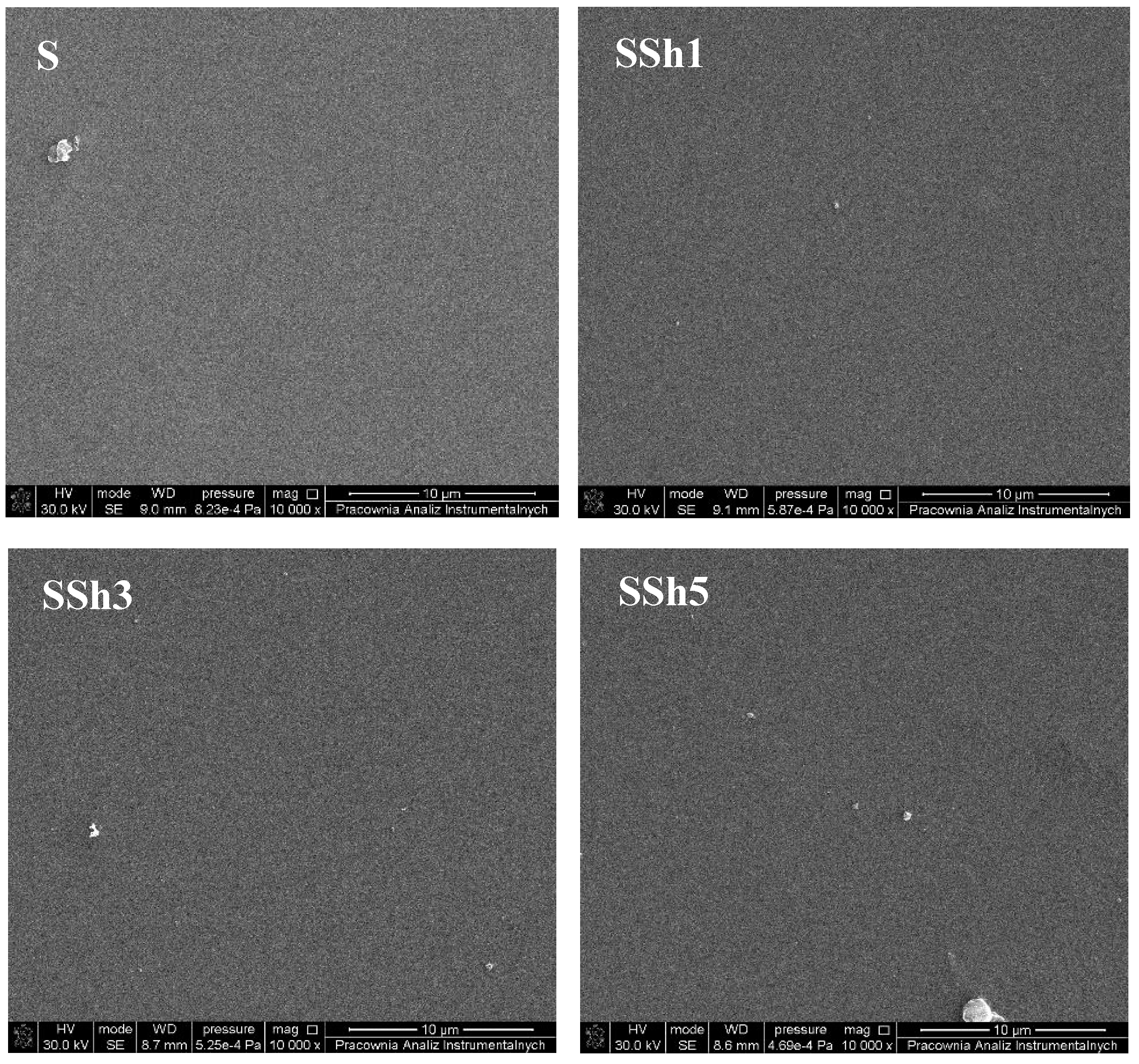
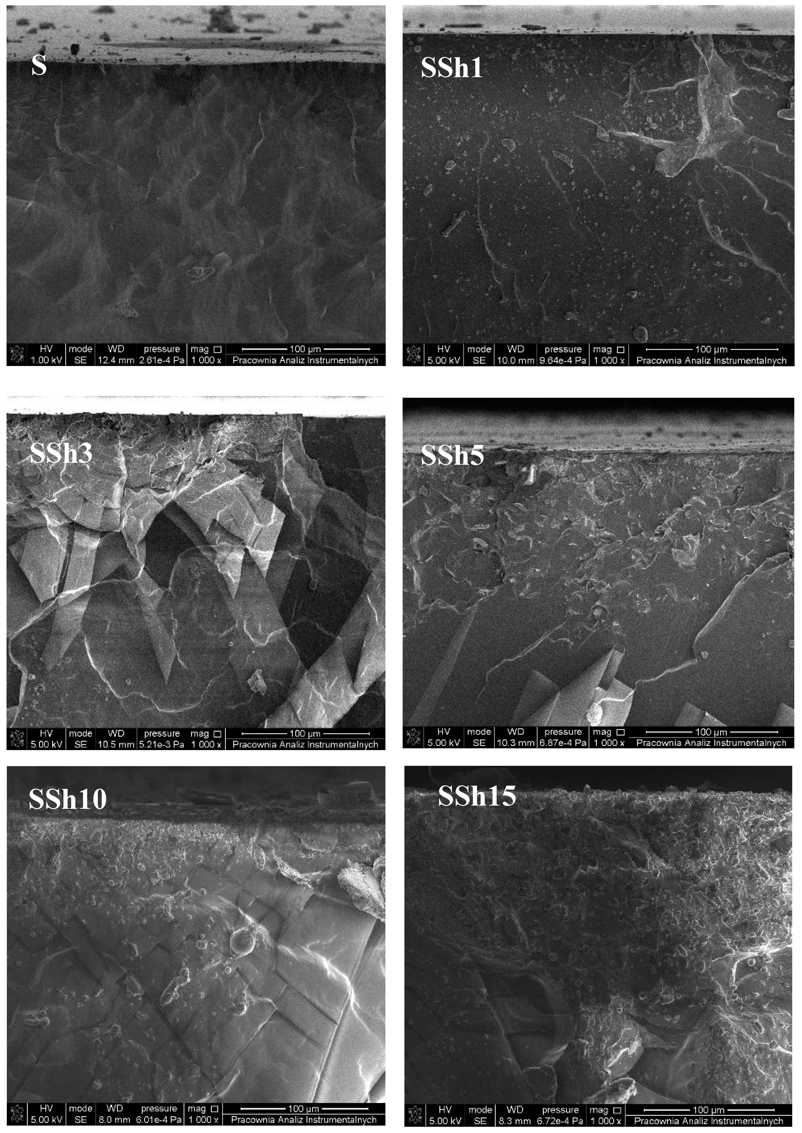
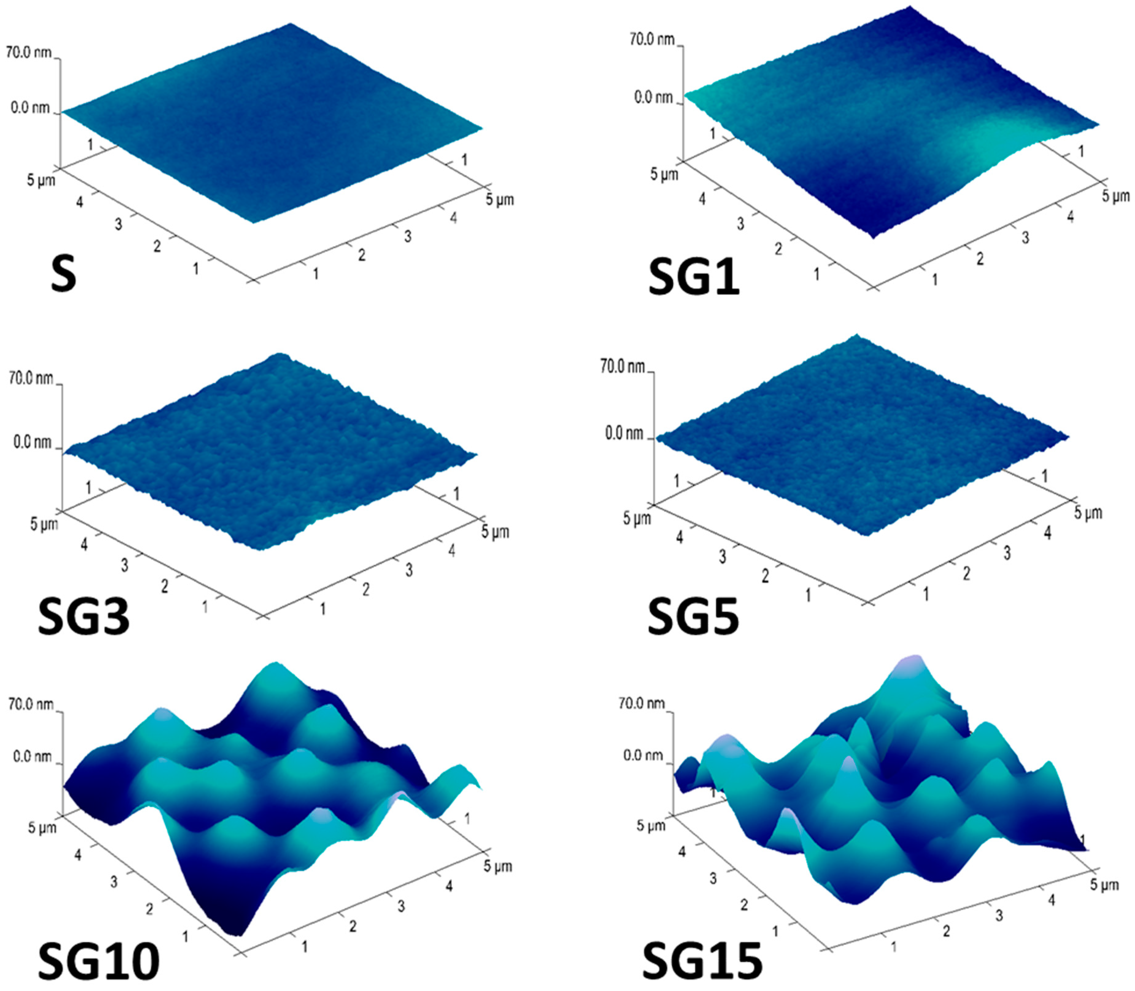
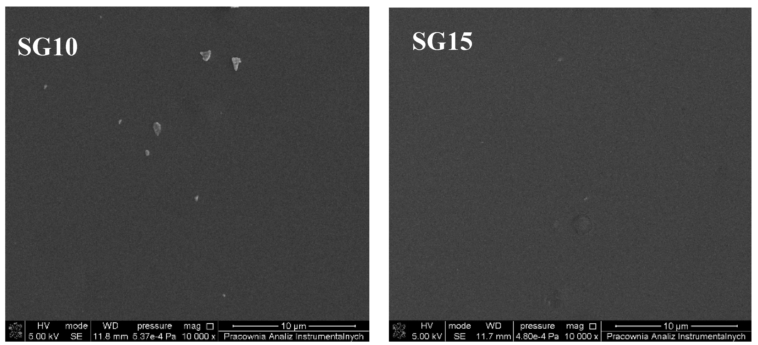
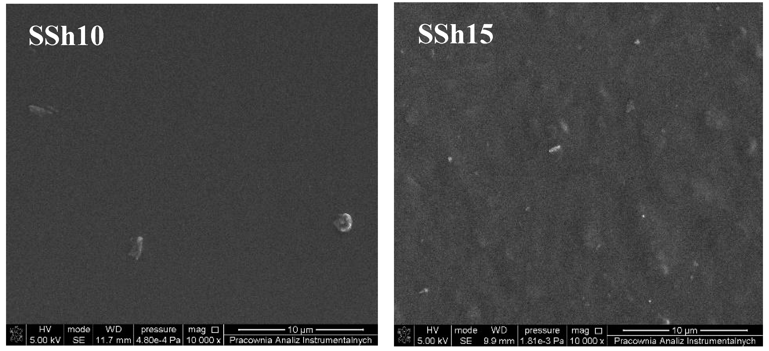
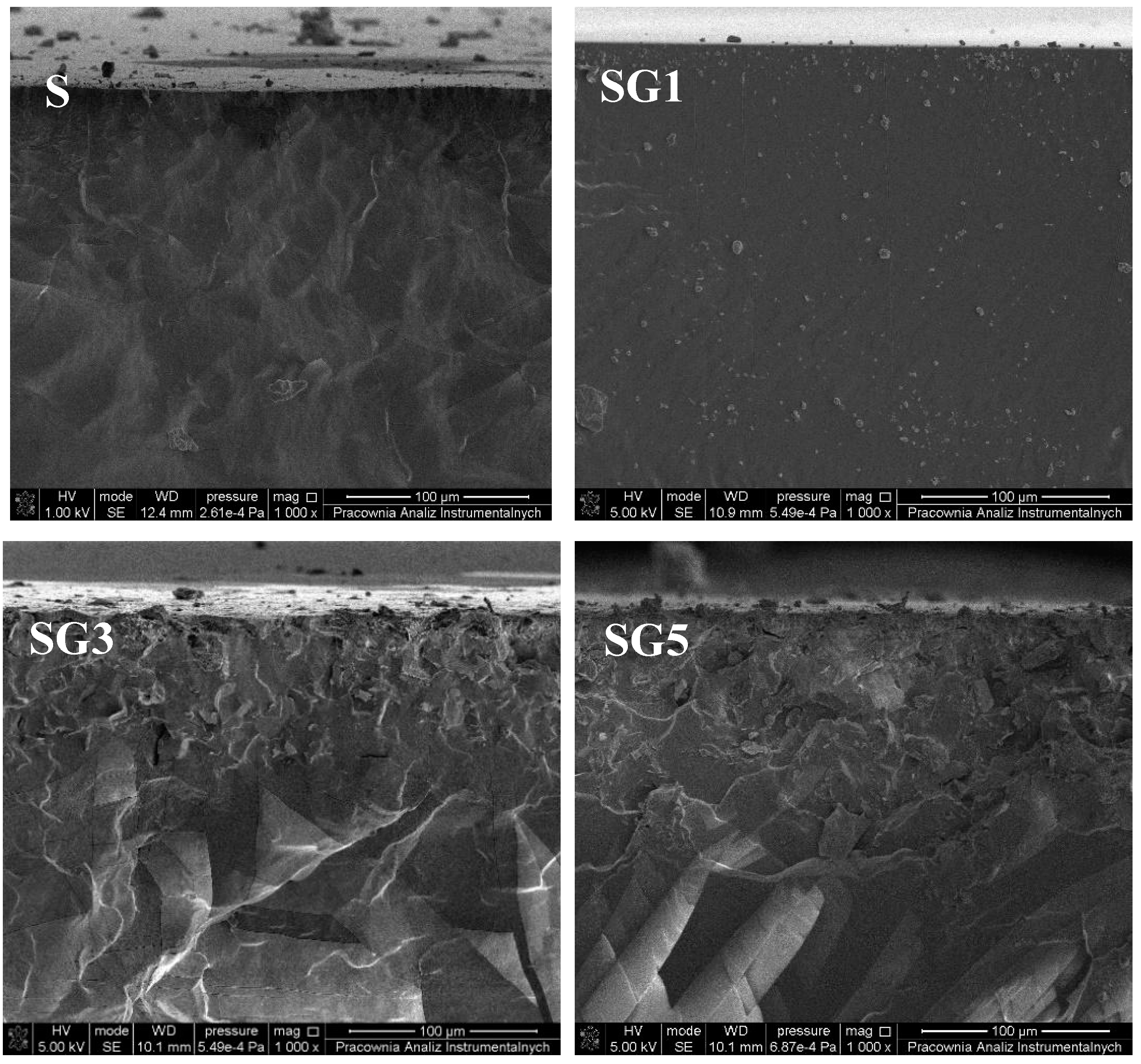
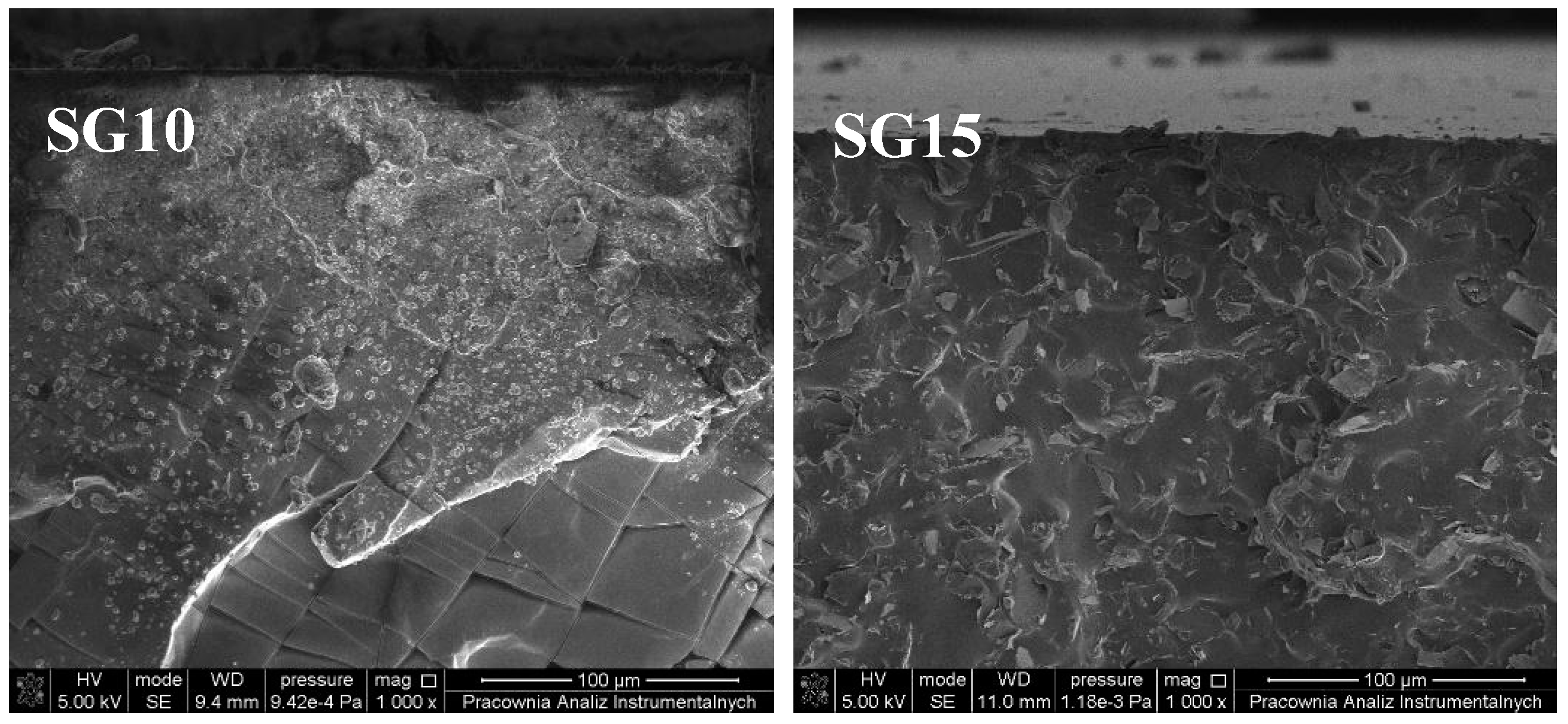
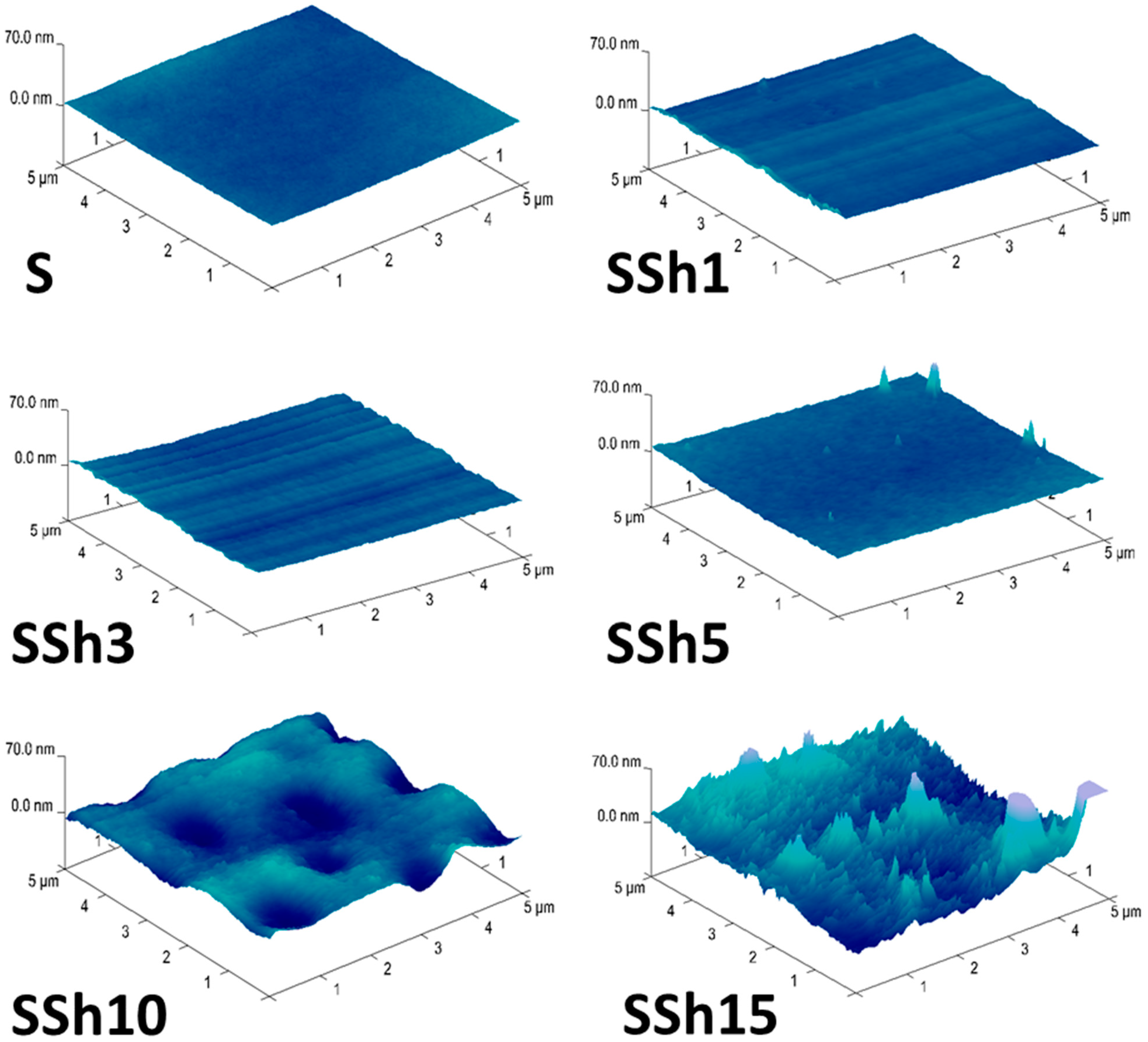
3.2. Morphology and Topography of Sylgard and Its Composites

In Figure 4, the surface of PDMS with and without the addition of graphite has been shown. Results obtained by means of the SEM technique clearly indicate that the addition of graphite does not significantly influence the morphology of the obtained composites. It has been noted that at 10,000× magnification, the surface of composites seems to be smooth, without scratches and pores. However, an increase in color intensity with an increase of graphite content can be observed. Moreover, some small impurities on the surface, probably formed during the preparation of samples for SEM analysis, are also visible.
The comparison of surface morphology of PDMS and its composites filled with shungite has been presented in Figure 5. The addition of shungite in the range between 1 and 10 wt.% does not cause significant changes in the morphology of the analyzed materials. The surface of composites SSh1, SSh3, SSh5, and SSh10 seems to be uncovered by any cracks, holes, or pores. However, it can be clearly observed that in the case of the sample containing 15 wt.% of shungite, the aggregates of filler cause differentiation of the surface morphology of the obtained material.
Cross-sections of pure polymer matrix and PDMS filled with both carbonaceous fillers are presented in Figure 6 and Figure 7. It can be clearly seen that while the surface of the obtained materials seems to be characterized by universally dispersed additives, the cross-sections reveal different dispersions of graphite and shungite introduced into the system. In the case of a sample with an addition of 1 wt.% of graphite, the filler seems to be uniformly distributed throughout the entire mass of the obtained composite. The increase in the amount of additive (3 and 5 wt.%) allows to obtain films where the graphite is deposited mostly in the upper level of the materials. The addition of 10 and 15 wt.% of graphite leads to the dispersion of filler throughout the entire mass of Sylgard.
The same tendency is observed in relation to composites containing shungite. In the case of materials consisting of Sylgard and 1, 10, and 15 wt.% of carbonaceous filler, shungite is evenly dispersed in the polymer matrix. However, in the case of 3 and 5 wt.% of filler content in the elastomer-based composites, the agglomerates of shungite are observed near the top layer of the studied materials. It is apparent that the dispersion of the analyzed fillers significantly depends on the quantity of the compound used in the process.
To compare the obtained results with the data published by other researchers, scientific papers devoted to the study of polymeric materials containing carbonaceous fillers were studied. Unfortunately, there are no publications presenting a cross-section of composites filled with graphite or shungite. The only fractographs were included in the work of Voigt et al. [47] where the melamine-formaldehyde–based laminates with an addition of 3 wt.% of shungite were analyzed. The characteristics of the polymeric matrix used in this study, as well as the quality of the image, preclude a viable comparison of the obtained results.
In an aim to analyze the topography of the obtained materials and to establish the effect of carbonaceous fillers on the roughness of the studied composites, atomic force microscopy was used. The AFM images of pure Sylgard and its composites with an addition of carbonaceous fillers, graphite and shungite, are shown in Figure 8 and Figure 9, respectively.
In the case of samples containing up to 5 wt.% of graphite as well as shungite, no significant changes in the Ra and Rq parameters have been observed. The data in Table 2 indicate that the values of average surface roughness (Ra) and root mean square surface roughness (Rq) range from about 1 to 5 nm. The increase in quantity of both fillers (10 and 15 wt.%) leads to a huge increase in values of all analyzed roughness parameters: Ra, Rq, and Rmax.
The other fact that must be taken into account is that the introduction of shungite caused more significant changes in the topography of the obtained composites than graphite, with a notable exception of the sample containing 5 wt.% of the filler. When comparing the SG5 and SSh5 samples, the average surface roughness and root mean square surface roughness are characterized by lower values in the case of materials modified by means of shungite. On summarizing the obtained results, it can clearly be seen that surfaces that seem to be smooth in SEM analysis are characterized by higher roughness parameters.

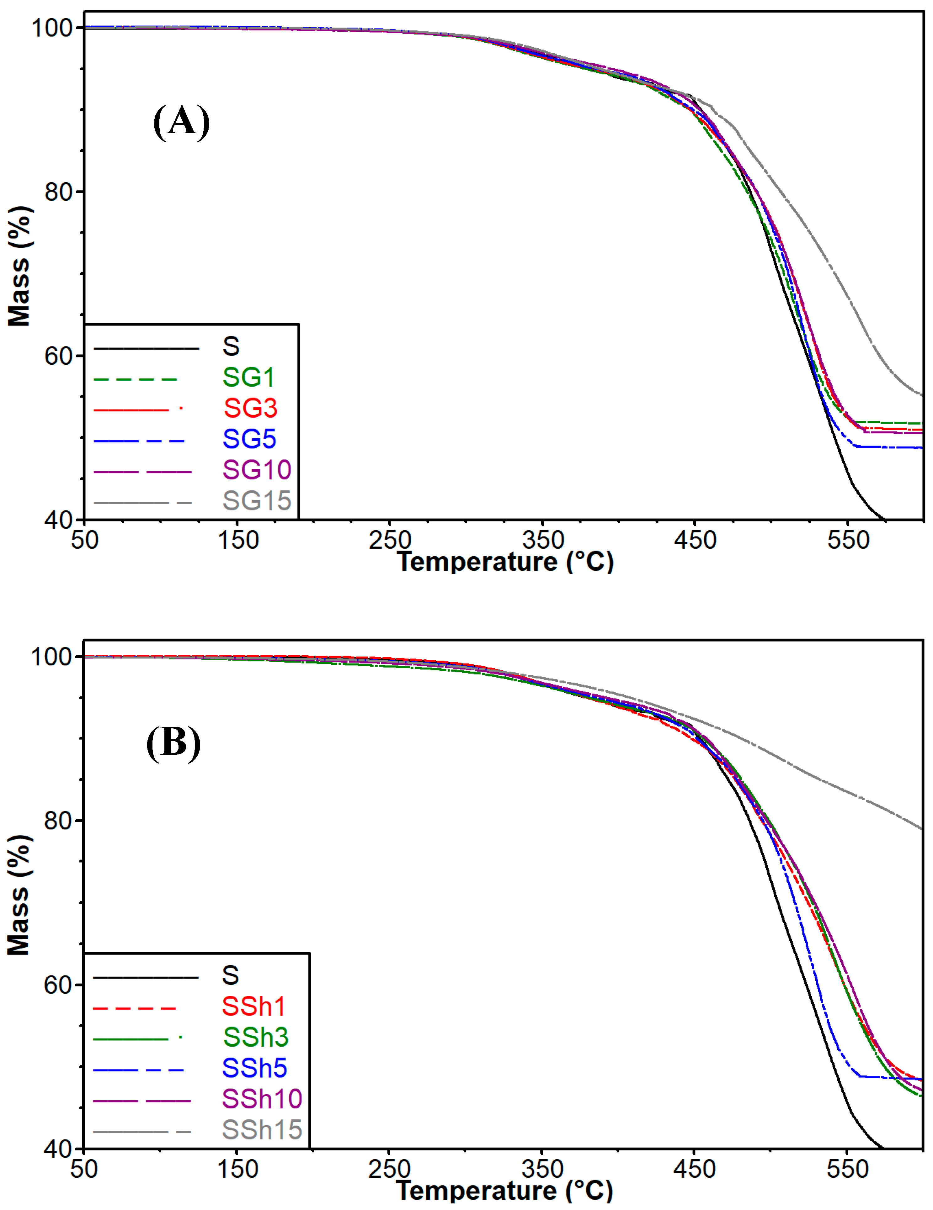
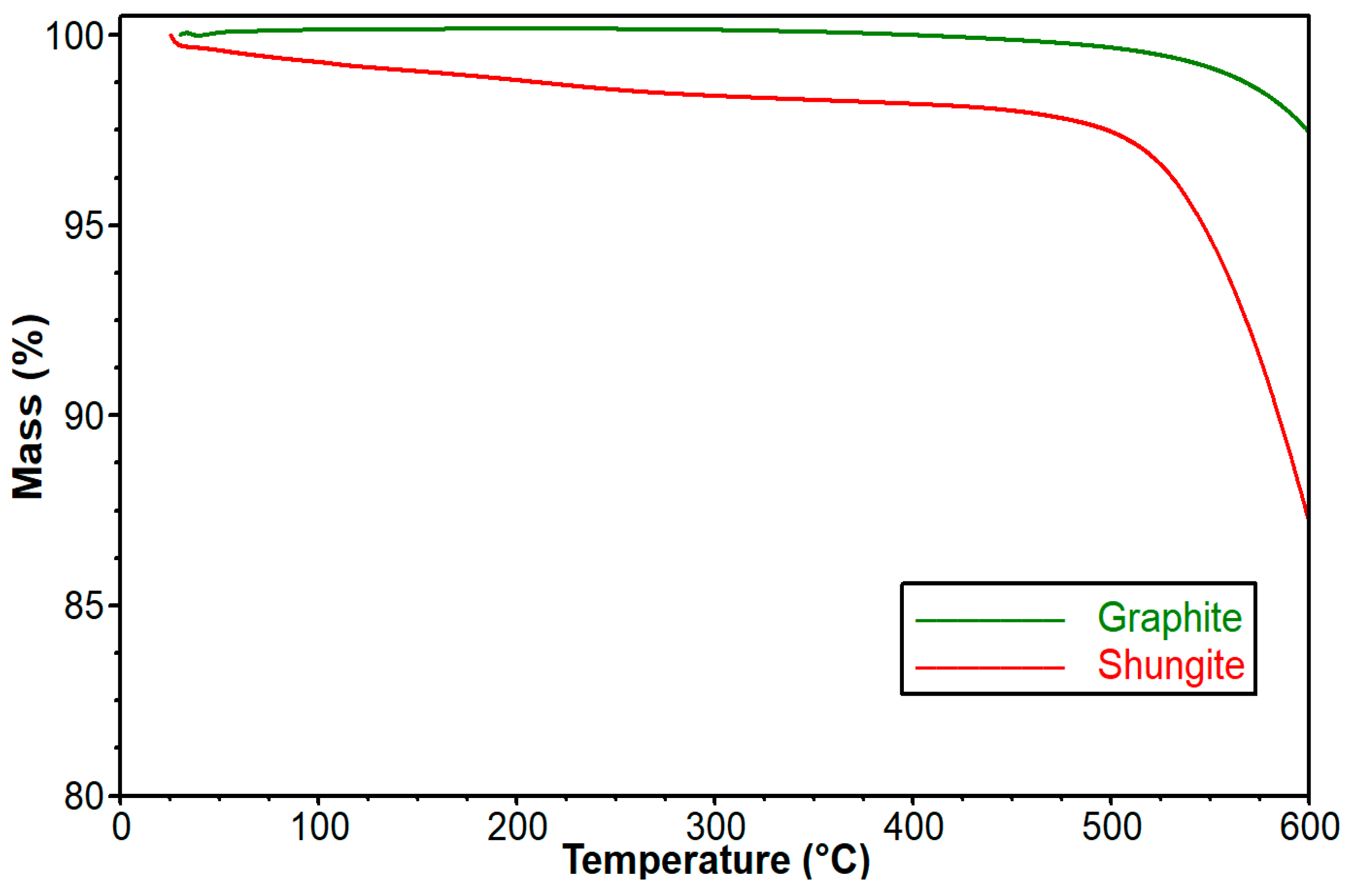
3.3. Influence of Graphite and Shungite on Thermal Stability of the Obtained Composites

Thermal stability is extremely important in the case of electroactive materials. For this reason, the thermal properties of the incorporated carbonaceous fillers and their effect on thermal stability of the obtained composites were established by means of thermogravimetric analysis (TG). Thermal stability of both fillers and composites as well as pure elastomer was discussed based on the temperature values corresponding to 5, 10, 30, and 50% mass loss (Table 3). In Figure 10, the changes of shungite and graphite mass along with the increase in temperature are shown.
Taking into account both fillers used in the study, it can be clearly seen that graphite is more resistant to temperature changes. In the case of graphite, the mass loss at temperature 600 °C does not exceed 3%, while shungite loses 5% and 10% at temperatures of 546.7 °C and 584.7 °C, respectively. According to the literature, the first stage of decomposition of shungite (about 1%) is related to the presence of moisture while at approx. 500 °C, sulfur evaporation can be observed [34]. Moreover in the cited work of Fujita et al. [34], it was established that heating shungite above 500 °C leads to the production of silicon carbide and changing carbon to CO2.
In Figure 11A,B the effect of carbonaceous fillers on thermal stability of Sylgard-based composites can be observed. The values of temperature at 5, 10, 30, and 50% mass loss for all studied films have been presented in Table 4.
In the case of pure Sylgard, its decomposition was described in the work of Johnson et al. [48]. It was indicated that the initial stage of thermal degradation is connected with the decomposition of [Si(CH3)2O]n and the dehydration of polymer. The obtained results, concerning the obtained Sylgard-based composites, indicate that the thermal stability of studied materials is strongly related to the type and amount of the filler introduced into the system. In the case of materials containing carbonaceous fillers, it was established that regardless of the amount of the applied additive, the temperatures at 5%, 30%, and 50%, mass loss increased in comparison to neat Sylgard. It is interesting, however, that in the case of 10% mass loss, the temperature of composites is higher than in the case of pure elastomer only after introduction of 10 and 15 wt.% of fillers.
Furthermore, it can be clearly noticed that despite graphite being more thermally stable compared to shungite, composites containing shungite are more resistant at high temperatures. The most significant increase in thermal stability was observed in the case of material consisting of Sylgard and 15 wt.% of shungite. Obtained results suggest the formation of char at the surface of the decomposed materials containing shungite. Taking into account that shungite is mostly composed of silica, it is reasonable to assume that char accumulating on the surface forms a barrier between the polymer and measurement atmosphere.
Analyzing the available literature, it can be concluded that there is little information devoted to the thermal stability of elastomers with an addition of carbonaceous fillers. For this reason, it makes use of graphite and shungite to improve the thermal properties of elastomeric materials, which an extremely interesting research issue.

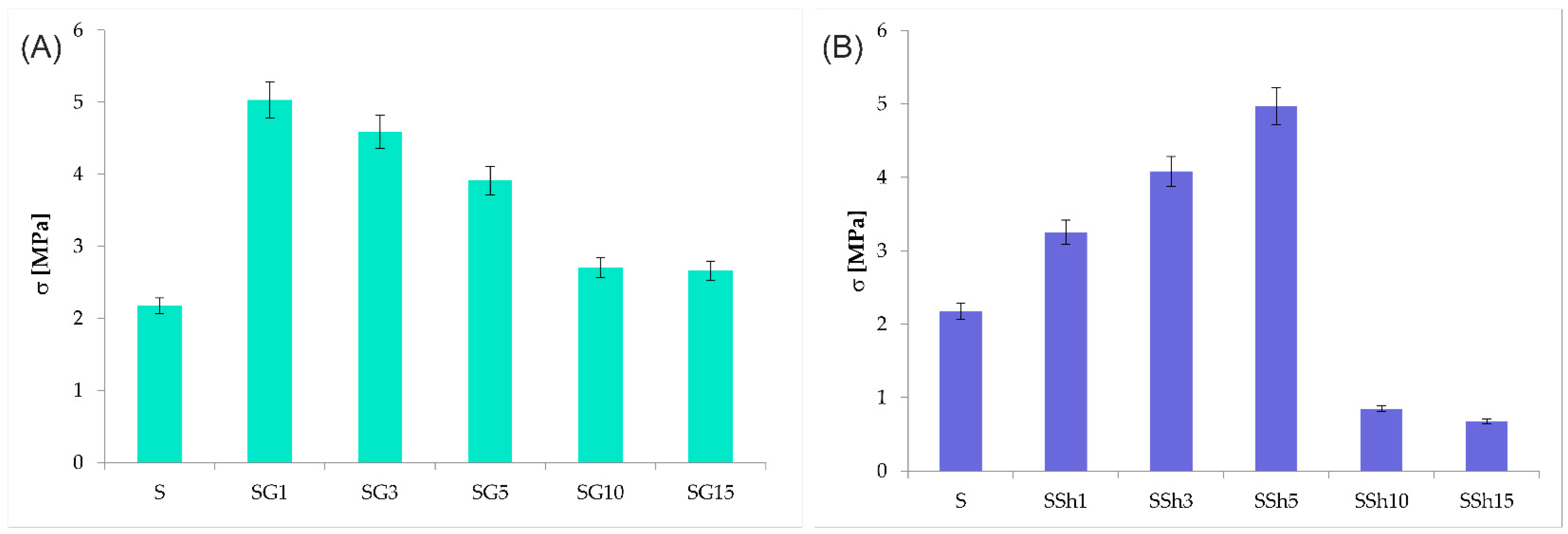
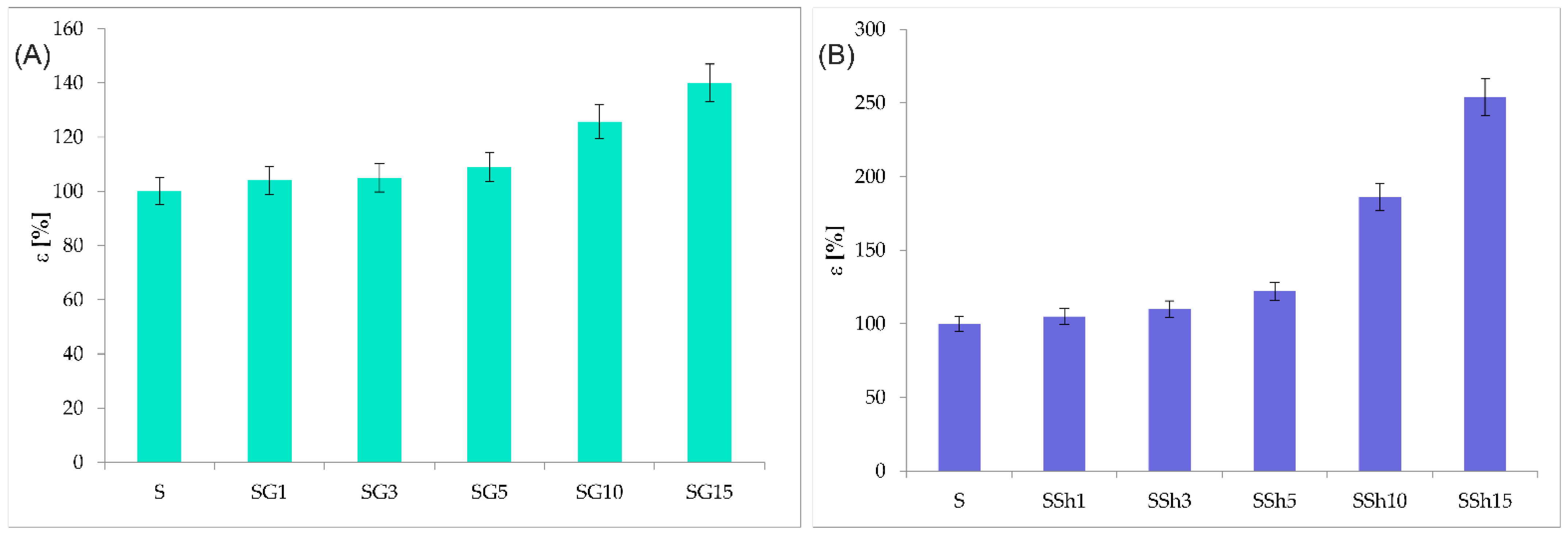
3.4. Mechanical Properties

In the case of electroactive materials, where the shape shifts result from a change in electrical voltage, mechanical properties seem to be essential. In particular, strength and elasticity count among the features that significantly depend on the type and quantity of the filler used in the procedure. For this reason, the changes in tensile strength and elongation at the break of obtained composites containing carbonaceous additives have been studied. In Figure 12A,B, the tensile strength of pure PDMS and its composites containing graphite and shungite respectively has been shown.
All samples containing graphite have displayed higher values of tensile strength in comparison to pure Sylgard. The SG1 sample containing the smallest amount of graphite (1 wt.%) proved to be most resistant to stretching among all of the composites tested. The tensile strength of this sample reached a value more than twice as high as the one recorded in relation to pure Sylgard. In the case of the remaining samples: SG3, SG5, SG10, and SG15, as the amount of graphite in the polymer matrix increased, decreased values of tensile stress in comparison with the SG1 sample have been recorded. It should be stressed, however, that the tensile stress for the remaining composites has achieved significantly higher values than in the case of pure Sylgard. The same tendency was observed in the work of Sarath et al. [49], where exfoliated graphite was introduced into silicone rubber. A decrease in tensile strength observed in the case of materials filled with 10 and 15 wt.% of graphite can suggest a weakening of the interfacial bonding between the additive and polymer matrix after introducing an increased amount of filler [50]. The obtained results are consistent with the data published in the work of Żenkiewicz et al. [41] where a significant decrease in σ was observed in relation to filler contents up to 10 wt.% of graphite. The same tendency was observed by Kalaitzidou et al. [51], who reported that at low loading level, the mechanical properties of polypropylene filled with graphite were significantly improved.
In the case of materials containing shungite, the changes in tensile strength have been completely different than in composites comprising Sylgard and graphite.
The samples SSh1, SSh3, and SSh5, have achieved higher tensile strength values than the sample without the addition of shungite. The sample containing 5 wt.% of shungite, however, showed the highest tensile strength, while in the case of materials containing graphite, the addition of only as little as 1 wt.% of the carbonaceous filler has allowed to obtain a similar value of tensile strength. Moreover, it should be stressed that after introducing 10 and 15 wt.% of shungite into the polymer matrix, a drastic reduction in the value of tensile stress was observed. It is well known that the introduction of different fillers into the PDMS matrix, in the majority of cases, increases durability by impeding polymer chain mobility. Based on the results published by Solovieva et al. [39] and presented in this work, it can clearly be seen that the addition of shungite improves molecular mobility.
In Figure 13A,B, elongation at the break of Sylgard and its composites filled with graphite and shungite respectively has been presented. In both cases, including materials consisting of the dielectric matrix and graphite as well as composites containing shungite, an increase in elongation at break has been observed. Analyzing the results encompassing the elongation at break values of samples containing graphite (Figure 13A), a contrary tendency, compared to the tensile strength of the tested composites, can be noticed. The SG15 sample, containing 15 wt.% of graphite, is characterized by the highest value of elongation at break (140 ± 7%). This observation confirms the most significant flexibility among all of the studied composites containing graphite.
Summarizing the results presented in Figure 12A and Figure 13A, it is possible to observe an increase in the flexibility and tensile strength of the studied materials containing graphite, regardless of its amount. However, it has to be stressed that in the case of tensile strength, the best results were achieved for composites filled with 1 wt.% of graphite, while the highest value of deformation at break were recorded in relation to material with an addition of 15 wt.% of the carbonaceous additive.
The incorporation of shungite into Sylgard results in a significant increase in the elongation at break values of all studied composites. As can be observed, the sample containing 15 wt.% of shungite was characterized by an elongation at break value more than twice as high as the value recorded in the case of pure Sylgard. The effect of shungite on the mechanical properties was analyzed in the work of Solovieva et al. [39] as well as Garishin et al. [52]. While determining the influence of the shungite addition on mechanical properties, they have established that the introduced carbonaceous filler consists of phases that differ in polarity. For this reason, considering the bipolarity of shungite, its compatibility and potential to mix with almost all types of materials has been explained.
In summary, the obtained results allow for presenting the dependence of mechanical properties on used carbonaceous fillers. It needs to be stressed that in the case of materials, tensile strength as well as elongation at break increase throughout the entire load range (1–15 wt.%) of the introduced graphite, while exceeding 5 wt.% of shungite results in a decrease in tensile strength.

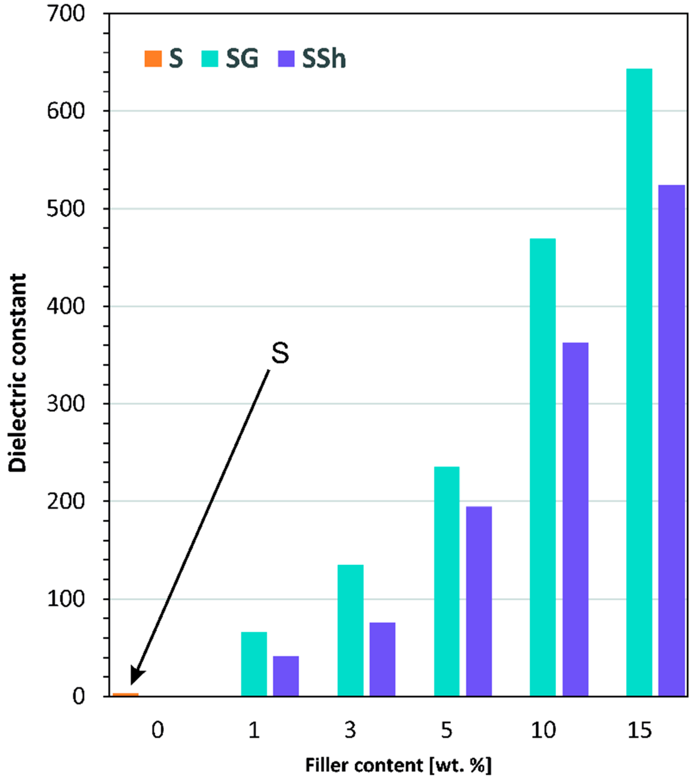
3.5. Dielectric Properties

The polymer capacity (C) representing the electric charge that can be deposited in a capacitor was determined at frequencies between 102 and 105 Hz and used to discuss the influence of graphite and shungite addition into poly(dimethylsiloxane) elastomer on its dielectric properties. According to the formula C = ε r C p , the capacity of a flat capacitor filled with a dielectric (C) with the same dimensions as the air capacitor is ε r -times higher than C p (the capacity of the air capacitor). Thus, changes in C values can be expressed as changes in ε r -dielectric constant of the tested capacitor. In Table 5, values of dielectric constant ( ε r ) and dielectric loss (φ) of all tested materials are summarized.
Analysis of the presented data leads to the conclusion that both applied fillers result in a substantial improvement of the dielectric properties of the elastomer matrix, represented by an increase of ε r values. The higher the filler content, the higher dielectric constant. Simultaneously, dielectric loss also increases in comparison to the neat Sylgard sample (S) however, φ values are still relatively low.
The dependence of ε r vs. wt.% of filler can be explained through the accumulation of charge carriers in the internal surface of the PDMS matrix. According to the Maxwell–Wagner–Sillars model, under an external electric field, the charge carriers can easily migrate to the grains, and these grains accumulated at the grain boundaries [53]. As a result of this process, large polarization is produced, and high dielectric constants are observed [54]. The higher the charge carriers’ content, the higher polarization, and finally, the higher ε r values. Similar behavior was observed earlier by Prasanna et al. [19] for polyaniline/exfoliated graphite flakes (PANI/EGF), by Li et al. [20] for polyvinylidene fluoride/graphite nanosheets (PVDF/GNs), and by Torğut et al. [25] for 2-hydroxyethyl methacrylate-co-N-isopropylacrylamide/graphite (poly(NIPAM-co-HEMA)/G) composites. The increase in ε r values with increasing wt.% of G and Sh in the composite can be also due to formation of conducting pillars of both fillers in the PDMS matrix.
The data collected in Table 5 indicate a slight decrease of dielectric constant ( ε r ) with the increase in frequency. This decrease is due to the reduction of space charge polarization effect, typical behavior of dielectric materials, also known as dielectric dispersion [17,55]. Poly(dimethylsiloxane) is a high molecular polymer of a chain-like structure. Under the external electric field, it will produce polarization. This phenomenon is limited due to the presence of chain bonds. When the frequency increases, the unidirectional duration of the electric field shortens, the degree of polarization is small, and the charge induced by polarization is less, so the dielectric constant decreases with the increase of frequency [56]. Similar observations have already been made by Li et al. [17] for polyvinylidene fluoride/expanded graphite composites and attributed to the mismatch of interfacial polarization of composites to the external electric field at elevated frequencies.
It can also be noted that for each particular additive content, and each frequency applied, the dielectric constants of SG composites are noticeably higher than those of SSh. At 1 kHz (Figure 14), 10 wt.% graphite incorporation caused a 144.9 × ε r increase, while the addition of shungite resulted in a 111.9× increase in the same modification conditions.
It is a fact that both graphite and shungite belong to the group of conducting fillers however, they substantially differ in carbon content (Table 1). While graphite consists mainly of carbon (82.8 wt.%), carbon constitutes only 15.19 wt.% of shungite. According to the data provided by Obradović et al. [31], Solovieva et al. [39], and mapping SEM/EDX images (Figure 3), the main constituents of shungite are silicon, iron, aluminum, calcium, sulfur, and magnesium oxides. Moreover, based on Table 1, it can be assumed that SiO2 is the most represented oxide in shungite, among others. The dielectric constant of different oxides is relatively low: 3.9 for SiO2 and 9 for Al2O3 [57,58], and what is essential, is lower than that of graphite ( ε r = 10 ÷ 15). Even if shungit also consists of highly dielectric iron oxide with ε r (α-Fe2O3) = 30, its content is relatively low. Thus, it can be concluded that the differences in the dielectric constants of SG and SSh composites come primarily from the composition of both additives.
The dielectric properties of the polymer composites can also vary depending on the size and shape of the conductive filler, the volume fraction, the method of preparation, and the interaction between the filler material and polymer [25,59,60]. As the method of composite preparation in the case of both G and Sh fillers is analogous, it is worth noting the substantial differences in the size and shape of G and Sh presented in Figure 1 and Figure 2 (shungite particles are significantly smaller than graphite), which can affect the additive dispersion and the final ε r values.
The comparison of presented results (Table 5) with those presented in the literature [17,19,20,61,62] show that both G and Sh are more efficient additives for ε r improvement than polydopamine/silicon dioxide/graphite oxide nanohybrid (PDA@SiO2@GO) filler and acts similarly to exfoliated graphite flakes (EGf) added to polyaniline (PANI), graphite sheets (GN), and expanded graphite (EG) added to polyvinylidene fluoride (PVDF).
As the problem of dielectric elastomers modification can be related to the deterioration of the breakdown strength, it is worth noting that in the case of the studied fillers, both G and Sh additives improved the tensile strength value. Lower σ values than those indicated for pure Sylgard, exhibit only SSh10 and SSh15 samples.

4. Conclusions

In the study two carbonaceous fillers, graphite and shungite, were used in order to alter the properties of Sylgard-based composites. Obtained results indicate that the dispersion of graphite, as well as shungite, in the PDMS matrix, significantly depends on the amount of the filler used in the procedure.
Taking into account the thermal stability of the obtained composites, it was established that even though graphite is characterized by more significant thermal resistance, improved thermal stability was observed in the case of the PDMS-based composites with the addition of shungite. The obtained results suggest that this phenomenon could be related to the higher content of silicon in the molecular composition of shungite, which can form a protective layer on the surface of the polymer during decomposition at high temperatures.
The comparison of mechanical properties of the tested composites revealed that the addition of graphite in the entire load range of the additive improved both tensile strength and flexibility of the obtained composites. The increase in the values of tensile strength and elongation at break of the Sylgard-graphite composites are most likely the result of a larger specific surface area and smaller size of graphite particles in comparison with shungite.
Studied composites were characterized by an improved dielectric constant after introducing both of the carbonaceous fillers. The observed increase of ε r is significantly connected with an accumulation of charge carriers in the internal surface of Sylgard. Moreover, the changes in dielectric constant can likely result from the presence of conducting pillars within both fillers in the PDMS matrix.
In summary, the obtained results reveal that both carbonaceous fillers, graphite and shungite, allow to obtain composites characterized by significantly improved thermal, mechanical, and dielectric properties. Nevertheless, as can be observed before the planned application, the type and amount of filler needs to be determined, bearing in mind the requirements and the purpose of the resulting material.

Author Contributions

Conceptualization, E.O.-K. and A.A.; methodology, E.O.-K. and A.A.; software, E.O.-K., A.A. and M.G.; validation, E.O.-K., A.A. and M.G.; formal analysis, E.O.-K., A.A. and M.G.; investigation, E.O.-K., A.A. and M.G.; resources, E.O.-K. and A.A.; data curation, E.O.-K., A.A. and M.G.; writing—original draft preparation, E.O.-K., A.A. and M.G.; writing—review and editing, E.O.-K., A.A., M.G. and S.G.-Z.; visualization, E.O.-K., A.A., M.G. and S.G.-Z.; supervision, E.O.-K. and A.A.; project administration, E.O.-K. and A.A.; funding acquisition, E.O.-K., A.A. and M.G. All authors have read and agreed to the published version of the manuscript.

Funding

This research received no external funding.

Institutional Review Board Statement

Not applicable.

Informed Consent Statement

Not applicable.

Data Availability Statement

The data presented in this study are available on request from the corresponding author.

Conflicts of Interest

The authors declare no conflict of interest.

References

  1. Kigozi, M.; Koech, R.K.; Kingsley, O.; Ojeaga, I.; Tebandeke, E.; Kasozi, G.N.; Onwualu, A.P. Synthesis and characterization of graphene oxide from locally mined graphite flakes and its supercapacitor applications. Results Mater. 2020, 7, 100113. [Google Scholar] [CrossRef]
  2. Jean-Mistral, C.; Basrour, S.; Chaillout, J.J. Comparison of electroactive polymers for energy scavenging applications. Smart Mater. Struct. 2010, 19, 12. [Google Scholar] [CrossRef]
  3. Cornogolub, A.; Cottinet, P.J.; Petit, L. Hybrid Energy Harvesting Using Electroactive Polymers Combined with Piezoelectric Materials. Adv. Sci. Technol. 2014, 96, 117–123. [Google Scholar] [CrossRef]
  4. Hassanpouryouzband, A.; Joonaki, E.; Edlmann, K.; Haszeldine, R.S. Offshore Geological Storage of Hydrogen: Is This Our Best Option to Achieve Net-Zero? ACS Energy Lett. 2021, 6, 2181–2186. [Google Scholar] [CrossRef]
  5. Jamal, E.M.A.; Joy, P.A.; Kurian, P.; Anantharaman, M.R. On the magnetic and dielectric properties of nickel-neoprene nanocomposites. Mater. Chem. Phys. 2010, 121, 154–160. [Google Scholar] [CrossRef]
  6. Yang, T.I.; Brown, R.N.C.; Kempel, L.C.; Kofinas, P. Controlled synthesis of core-shell iron-silica nanoparticles and their magneto-dielectric properties in polymer composites. Nanotechnology 2011, 22, 105601. [Google Scholar] [CrossRef] [PubMed] [Green Version]
  7. Kofod, G.; Risse, S.; Stoyanov, H.; McCarthy, D.N.; Sokolov, S.; Kraehnert, R. Broad-spectrum enhancement of polymer composite dielectric constant at ultralow volume fractions of silica-supported copper nanoparticles. ACS Nano 2011, 5, 1623–1629. [Google Scholar] [CrossRef] [PubMed]
  8. Stiubianu, G.; Bele, A.; Cazacu, M.; Racles, C.; Vlad, S.; Ignat, M. Dielectric silicone elastomers with mixed ceramic nanoparticles. Mater. Res. Bull. 2015, 71, 67–74. [Google Scholar] [CrossRef] [Green Version]
  9. Yang, L.; Hu, Y.; Lu, H.; Song, L. Morphology, thermal, and mechanical properties of flame-retardant silicone rubber/montmorillonite nanocomposites. J. Appl. Polym. Sci. 2006, 99, 3275–3280. [Google Scholar] [CrossRef]
  10. Carpi, F.; De Rossi, D. Improvement of electromechanical actuating performances of a silicone dielectric elastomer by dispersion of titanium dioxide powder. IEEE Trans. Dielectr. Electr. Insul. 2005, 12, 835–843. [Google Scholar] [CrossRef]
  11. Zhang, X.; Wen, H.; Chen, X.; Wu, Y.; Xiao, S. Study on the thermal and dielectric properties of SrTiO3/epoxy nanocomposites. Energies 2017, 10, 692. [Google Scholar] [CrossRef] [Green Version]
  12. Romasanta, L.J.; Leret, P.; Casaban, L.; Hernández, M.; De La Rubia, M.A.; Fernández, J.F.; Kenny, J.M.; Lopez-Manchado, M.A.; Verdejo, R. Towards materials with enhanced electro-mechanical response: CaCu 3Ti4O12-polydimethylsiloxane composites. J. Mater. Chem. 2012, 22, 24705–24712. [Google Scholar] [CrossRef] [Green Version]
  13. Fang, X.; Pan, L.; Yao, J.; Yin, S.; Wang, Y.; Li, Q.; Yang, J. Controllable dielectric properties and strong electromagnetic wave absorption properties of SiC/spherical graphite-AlN microwave-attenuating composite ceramics. Ceram. Int. 2021, 47, 22636–22645. [Google Scholar] [CrossRef]
  14. Xi, X.; Chung, D.D.L. Dielectric behavior of graphite, with assimilation of the AC permittivity, DC polarization and DC electret. Carbon N. Y. 2021, 181, 246–259. [Google Scholar] [CrossRef]
  15. Li, X.; Wang, X.; Weng, L.; Yu, Y.; Zhang, X.; Liu, L.; Wang, C. Dielectrical properties of graphite nanosheets/PVDF composites regulated by coupling agent. Mater. Today Commun. 2019, 21, 100705. [Google Scholar] [CrossRef]
  16. Kumar, P.; Penta, S.; Mahapatra, S.P. Dielectric Properties of Graphene Oxide Synthesized by Modified Hummers’ Method from Graphite Powder. Integr. Ferroelectr. 2019, 202, 41–51. [Google Scholar] [CrossRef]
  17. Tjong, S.C.; Li, Y.C.; Li, R.K.Y. Frequency and temperature dependences of dielectric dispersion and electrical properties of polyvinylidene fluoride/expanded graphite composites. J. Nanomater. 2010, 2010, 261748. [Google Scholar] [CrossRef] [Green Version]
  18. Bhuyan, M.S.A.; Uddin, M.N.; Islam, M.M.; Bipasha, F.A.; Hossain, S.S. Synthesis of graphene. Int. Nano Lett. 2016, 6, 65–83. [Google Scholar] [CrossRef] [Green Version]
  19. Prasanna, P.B.; Avadhani, D.N.; Muralidhara, H.B.; Revanasiddappa, M. Synthesis, Characterization and Enhanced Dielectric Constant of Polyaniline-Exfoliated Graphite Flakes Composites. IJLTEMAS 2014, III, 55–60. [Google Scholar]
  20. Li, Y.C.; Li, R.K.Y.; Tjong, S.C. Electrical transport properties of graphite sheets doped polyvinylidene fluoride nanocomposites. J. Mater. Res. 2010, 25, 1645–1648. [Google Scholar] [CrossRef]
  21. Rzeczkowski, P.; Krause, B.; Pötschke, P. Characterization of highly filled PP/graphite composites for adhesive joining in fuel cell applications. Polymers 2019, 11, 462. [Google Scholar] [CrossRef] [Green Version]
  22. Metz, R.; Blanc, C.; Dominguez, S.; Tahir, S.; Leparc, R.; Hassanzadeh, M. Nonlinear field dependent conductivity dielectrics made of graphite nanoplatelets filled composites. Mater. Lett. 2021, 292, 129611. [Google Scholar] [CrossRef]
  23. Biryan, F.; Abubakar, A.M.; Demirelli, K. Product analysis, electrical and dielectric properties depending on thermal influence of poly(N-isopropyl acrylamide)/graphite-filled composite. Thermochim. Acta 2018, 669, 66–79. [Google Scholar] [CrossRef]
  24. Parida, S.; Parida, R.K.; Parida, B.N.; Padhee, R.; Nayak, N.C. Structural, thermal and dielectric behaviour of exfoliated graphite nanoplatelets (xGnP) filled EVA/EOC blend composites. Mater. Sci. Eng. B Solid-State Mater. Adv. Technol. 2022, 275, 115497. [Google Scholar] [CrossRef]
  25. Torğut, G.; Biryan, F.; Demirelli, K. Effect of graphite particle fillers on dielectric and conductivity properties of poly(NIPAM-co-HEMA). Bull. Mater. Sci. 2019, 42. [Google Scholar] [CrossRef] [Green Version]
  26. Wu, L.; Yang, D. Dielectric Properties and Thermal Conductivity of Poly(vinylidene fluoride)-Based Composites with Graphite Nanosheet and Nickel Particle. J. Nanosci. Nanotechnol. 2019, 19, 3591–3596. [Google Scholar] [CrossRef]
  27. Kranauskaite, I.; Macutkevic, J.; Kuzhir, P.; Volynets, N.; Paddubskaya, A.; Bychanok, D.; Maksimenko, S.; Banys, J.; Juskenas, R.; Bistarelli, S.; et al. Dielectric properties of graphite-based epoxy composites. Phys. Status Solidi Appl. Mater. Sci. 2014, 211, 1623–1633. [Google Scholar] [CrossRef] [Green Version]
  28. Tolvanen, J.; Hannu, J.; Nelo, M.; Juuti, J.; Jantunen, H. Dielectric properties of novel polyurethane-PZT-graphite foam composites. Smart Mater. Struct. 2016, 25, 95039. [Google Scholar] [CrossRef] [Green Version]
  29. Xu, W.H.; Tan, L.C.; Qin, S.; He, Y.; Wu, T.; Qu, J. ping Efficient fabrication of highly exfoliated and evenly dispersed high-density polyethylene/expanded graphite nanocomposite with enhanced dielectric constant and extremely low dielectric loss. Compos. Part A Appl. Sci. Manuf. 2021, 142, 106242. [Google Scholar] [CrossRef]
  30. Feng, Y.; Zhou, J.; Chen, P.; Bo, M.; Deng, Q. Filler-synergy route for optimising dielectric features of novel polymer-based ternary composite films bearing Fe2TiO5 pseudo-perovskite and graphite particles. Ceram. Int. 2021, 47, 8357–8364. [Google Scholar] [CrossRef]
  31. Obradović, N.; Gigov, M.; Ðorđević, A.; Kern, F.; Dmitrović, S.; Matović, B.; Ðorđević, A.; Tshantshapanyan, A.; Vlahović, B.; Petrović, P.; et al. Shungite—A carbon-mineral rock material: Its sinterability and possible applications. Process. Appl. Ceram. 2019, 13, 89–97. [Google Scholar] [CrossRef] [Green Version]
  32. Moshnikov, I.A.; Kovalevski, V.V. Composite materials based on nanostructured shungite filler. Mater. Today Proc. 2018, 5, 25971–25975. [Google Scholar] [CrossRef]
  33. Sajo, M.E.J.; Kim, C.S.; Kim, S.K.; Shim, K.Y.; Kang, T.Y.; Lee, K.J. Antioxidant and Anti-Inflammatory Effects of Shungite against Ultraviolet B Irradiation-Induced Skin Damage in Hairless Mice. Oxid. Med. Cell. Longev. 2017, 2017. [Google Scholar] [CrossRef] [Green Version]
  34. Fujita, T.; Aoki, T.; Ponou, J.; Dodbiba, G.; He, C.; Wang, K.; Ning, S.; Chen, H.; Wei, Y. Removal of impurities from shungite via a combination of physical and chemical treatments. Minerals 2021, 11, 245. [Google Scholar] [CrossRef]
  35. Antonets, I.V.; Golubev, Y.A.; Shcheglov, V.I.; Sun, S. Electromagnetic shielding effectiveness of lightweight and flexible ultrathin shungite plates. Curr. Appl. Phys. 2021, 29, 97–106. [Google Scholar] [CrossRef]
  36. Antonets, I.V.; Golubev, Y.A.; Shcheglov, V.I. Evaluation of microstructure and conductivity of two-phase materials by the scanning spreading resistance microscopy (the case of shungite). Ultramicroscopy 2021, 222, 113212. [Google Scholar] [CrossRef] [PubMed]
  37. Golubev, Y.A.; Antonets, I.V.; Shcheglov, V.I. Static and dynamic conductivity of nanostructured carbonaceous shungite geomaterials. Mater. Chem. Phys. 2019, 226, 195–203. [Google Scholar] [CrossRef]
  38. Barashkova, I.I.; Komova, N.N.; Motyakin, M.V.; Potapov, E.E.; Wasserman, A.M. Shungite-elastomer interface layers. Dokl. Phys. Chem. 2014, 456, 83–85. [Google Scholar] [CrossRef]
  39. Solov’eva, A.B.; Neschadina, L.E.; Rozhkova, N.N.; Zaidenberg, A.Z. Shungite effect on some properties of elastomers. Ext. Abstr. 23rd Bienn. Conf. Carbon. Pennsylvania. USA 1997, 2, 248–249. [Google Scholar]
  40. Frąc, M.; Szudek, W.; Szołdra, P.; Pichór, W. The applicability of shungite as an electrically conductive additive in cement composites. J. Build. Eng. 2022, 45, 103469. [Google Scholar] [CrossRef]
  41. Zenkiewicz, M.; Richert, J.; Rytlewski, P.; Richert, A. Comparative analysis of shungite and graphite effects on some properties of polylactide composites. Polym. Test. 2011, 30, 429–435. [Google Scholar] [CrossRef]
  42. Olewnik-Kruszkowska, E.; Brzozowska, W.; Adamczyk, A.; Gierszewska, M.; Wojtczak, I.; Sprynskyy, M. Effect of diatomaceous biosilica and talc on the properties of dielectric elastomer based composites. Energies 2020, 13, 828. [Google Scholar] [CrossRef]
  43. Andryushchenko, N.D.; Safonov, A.V.; Babich, T.L.; Ivanov, P.V.; Konevnik, Y.V.; Kondrashova, A.A.; Proshin, I.M.; Zakharova, E.V. Sorption characteristics of materials of the filtration barrier in upper aquifers contaminated with radionuclides. Radiochemistry 2017, 59, 414–424. [Google Scholar] [CrossRef]
  44. Diyuk, V.E.; Ishchenko, O.V.; Loginova, O.B.; Melnik, L.M.; Kisterska, L.D.; Garashchenko, V.V.; Lisovenko, S.O.; Beda, O.A.; Tkachuk, N.A.; Shevchenko, O.Y.; et al. Recovery of Adsorption Properties of Shungite. J. Superhard Mater. 2019, 41, 221–228. [Google Scholar] [CrossRef]
  45. Siburian, R.; Sihotang, H.; Lumban Raja, S.; Supeno, M.; Simanjuntak, C. New route to synthesize of graphene nano sheets. Orient. J. Chem. 2018, 34, 182–187. [Google Scholar] [CrossRef] [Green Version]
  46. Ogbu, C.I.; Feng, X.; Dada, S.N.; Bishop, G.W. Screen-printed soft-nitrided carbon electrodes for detection of hydrogen peroxide. Sensors 2019, 19, 3741. [Google Scholar] [CrossRef] [PubMed] [Green Version]
  47. Voigt, B.; McQueen, D.H.; Pelišková, M.; Rozhkova, N. Electrical and mechanical properties of melamine-formaldehyde-based laminates with shungite filler. Polym. Compos. 2005, 26, 552–562. [Google Scholar] [CrossRef]
  48. Johnson, R.T.; Biefeld, R.M.; Sayre, J.A. High-temperature electrical conductivity and thermal decomposition of Sylgard® 184 and mixtures containing hollow microspherical fillers. Polym. Eng. Sci. 1984, 24, 435–441. [Google Scholar] [CrossRef]
  49. Sarath, P.S.; Samson, S.V.; Reghunath, R.; Pandey, M.K.; Haponiuk, J.T.; Thomas, S.; George, S.C. Fabrication of exfoliated graphite reinforced silicone rubber composites-Mechanical, tribological and dielectric properties. Polym. Test. 2020, 89. [Google Scholar] [CrossRef]
  50. Mohanavel, V.; Rajan, K.; Suresh Kumar, S.; Vijayan, G.; Vijayanand, M.S. Study on mechanical properties of graphite particulates reinforced aluminium matrix composite fabricated by stir casting technique. Mater. Today Proc. 2018, 5, 2945–2950. [Google Scholar] [CrossRef]
  51. Kalaitzidou, K.; Fukushima, H.; Drzal, L.T. Mechanical properties and morphological characterization of exfoliated graphite-polypropylene nanocomposites. Compos. Part A Appl. Sci. Manuf. 2007, 38, 1675–1682. [Google Scholar] [CrossRef]
  52. Garishin, O.K.; Shadrin, V.V.; Belyaev, A.Y.; Kornev, Y.V. Micro and nanoshungites-Perspective mineral fillers for rubber composites used in the tires. Mater. Phys. Mech. 2018, 40, 56–62. [Google Scholar] [CrossRef]
  53. Ravikumar, K.; Palanivelu, K.; Ravichandran, K. Dielectric properties of natural rubber composites filled with graphite. Mater. Today Proc. 2019, 16, 1338–1343. [Google Scholar] [CrossRef]
  54. Khan, J.A.; Qasim, M.; Singh, B.R.; Singh, S.; Shoeb, M.; Khan, W.; Das, D.; Naqvi, A.H. Synthesis and characterization of structural, optical, thermal and dielectric properties of polyaniline/CoFe2O4 nanocomposites with special reference to photocatalytic activity. Spectrochim. Acta Part A Mol. Biomol. Spectrosc. 2013, 109, 313–321. [Google Scholar] [CrossRef] [PubMed]
  55. Deng, Q.; Li, X.; Li, Q.; Xia, X.; He, C.; Feng, Y.; Peng, C. Well-balanced high permittivity and low dielectric loss obtained in PVDF/graphite/BN ternary composites by depressing interfacial leakage conduction. Microelectron. Eng. 2020, 231, 111404. [Google Scholar] [CrossRef]
  56. Wang, B.; Liu, Y.; Dong, M.; Zuo, G. Study on changing the dielectric constant and radar reflection of foamed polyurethane by adding graphite. J. Phys. Conf. Ser. 2021, 1980. [Google Scholar] [CrossRef]
  57. Azadmanjiri, J.; Berndt, C.C.; Wang, J.; Kapoor, A.; Srivastava, V.K.; Wen, C. A review on hybrid nanolaminate materials synthesized by deposition techniques for energy storage applications. J. Mater. Chem. A 2014, 2, 3695–3708. [Google Scholar] [CrossRef]
  58. Robertson, J. High dielectric constant oxides. Eur. Phys. J. Appl. Phys. 2004, 28, 265–291. [Google Scholar] [CrossRef] [Green Version]
  59. Xi, X.; Chung, D.D.L. Role of grain boundaries in the dielectric behavior of graphite. Carbon N. Y. 2021, 173, 1003–1019. [Google Scholar] [CrossRef]
  60. Pal, R.; Akhtar, M.J.; Kar, K.K. Study on dielectric properties of synthesized exfoliated graphite reinforced epoxy composites for microwave processing. Polym. Test. 2018, 70, 8–17. [Google Scholar] [CrossRef]
  61. Liu, L.; Lei, Y.; Zhang, Z.; Liu, J.; Lv, S.; Guo, Z. Fabrication of PDA@SiO2@rGO/PDMS dielectric elastomer composites with good electromechanical properties. React. Funct. Polym. 2020, 154, 104656. [Google Scholar] [CrossRef]
  62. Li, Y.; Li, R.K.Y.; Tjong, S.C. Fabrication and properties of PVDF/expanded graphite nanocomposites. E-Polymers 2009, 19, 1–13. [Google Scholar] [CrossRef]
Figure 1. SEM images of graphite with magnification (A) 5000× and (B) 50,000×.
Energies 15 00152 g001
Figure 2. SEM images of the shungite with magnification (A) 5000× and (B) 50,000×.
Energies 15 00152 g002
Figure 3. SEM-EDX images of (A) graphite and (B) shungite.
Energies 15 00152 g003
Figure 4. SEM images of elastomer and polymer matrix filled with graphite.
Energies 15 00152 g004aEnergies 15 00152 g004b
Figure 5. SEM images of elastomer and polymer matrix filled with shungite.
Energies 15 00152 g005aEnergies 15 00152 g005b
Figure 6. Cross sections of Sylgard and composites containing graphite.
Energies 15 00152 g006aEnergies 15 00152 g006b
Figure 7. Cross sections of Sylgard and composites containing shungite.
Energies 15 00152 g007
Figure 8. Atomic Force Microscope (AFM) images of pure Sylgard and its composites containing graphite.
Energies 15 00152 g008
Figure 9. AFM images of pure Sylgard and its composites containing shungite.
Energies 15 00152 g009
Figure 10. Thermogravimetric curves for carbonaceous filler: shungite and graphite.
Energies 15 00152 g010
Figure 11. (A) Thermogravimetric curves for Sylgard (S) and its composites containing graphite. (B) Thermogravimetric curves for Sylgard (S) and its composites containing shungite.
Energies 15 00152 g011
Figure 12. Tensile strength of pure Sylgard and its composites with an addition of (A) graphite and (B) shungite.
Energies 15 00152 g012
Figure 13. Elongation at break of pure PDMS (S) and its composites with an addition of (A) graphite and (B) shungite.
Energies 15 00152 g013
Figure 14. Comparison of dielectric constant for poly(dimethylsiloxane) (S) modified with graphite (SG) and shungite (SSh) at 1000 Hz.
Energies 15 00152 g014
Table 1. Composition of carbonaceous fillers.
SampleContent [%]
COSiFeAlCaSMgCu
Graphite82.8611.981.810.911.220.280.330.340.27
Shungite15.1950.7624.712.283.721.260.840.800.44
Table 2. Roughness parameters of pure Sylgard and Sylgard-based composites containing carbonaceous fillers.
SampleRq [nm]Ra [nm]Rmax [nm]
S1.140.867.94
SG11.220.988.95
SG31.731.3217.42
SG55.044.0129.91
SG1018.2014.40107.30
SG1523.5018.40149.20
SSh11.871.4120.20
SSh32.201.6920.60
SSh52.261.7354.40
SSh106.815.4266.20
SSh1519.0612.11231.00
Table 3. Thermal stability of used carbonaceous fillers.
SampleTemperature [°C] at Mass Loss
5%10%30%50%
Graphite>600>600>600>600
Shungite546.7584.7>600>600
Table 4. TG data for pure Sylgard and its composites.
SampleTemperature [°C] at Mass Loss
5%10%30%50%
S375.8453.1504.5541.6
SG1377.0449.8508.3>600
SG3381.3450.6511.6>600
SG5383.6450.5513.2>600
SG10386.0454.0514.5>600
SG15392.2462.6541.5>600
SSh1378.2448.8524.5582.0
SSh3379.5454.5524.4579.6
SSh5384.4452.9518.7556.2
SSh10389.9458.2528.8579.3
SSh15408.1481.4>600>600
Table 5. Dielectric properties of graphite and shungite doped poly(dimethylsiloxane) elastomer.
SampleFrequency [Hz]
102103104105
ε r φ ε r φ ε r φ ε r φ
S3.2770.0053.2140.0173.1200.0173.0560.010
SG170.7300.20065.8520.10062.1450.10059.5110.300
SG3141.2610.200135.0900.600108.4850.200101.3600.500
SG5241.2610.300235.0901.000208.4580.400201.3600.300
SG10475.8630.000469.0880.300468.5240.000464.5720.000
SG15656.2150.300643.0911.000636.2901.000628.0570.600
SSh142.6600.60041.4300.30033.5090.30030.3030.000
SSh380.7300.55075.8520.25072.1450.25069.5110.000
SSh5198.3990.000194.6410.200192.7610.000190.7320.000
SSh10364.5160.300362.7631.000359.2581.000356.1020.600
SSh15535.1440.400524.4410.000519.2420.000511.5970.1000
ε r —dielectric constant. φ—dielectric loss.
Publisher’s Note: MDPI stays neutral with regard to jurisdictional claims in published maps and institutional affiliations.

