
A Review of the Optimization Design and Control for Ocean Wave Power Generation Systems


Abstract
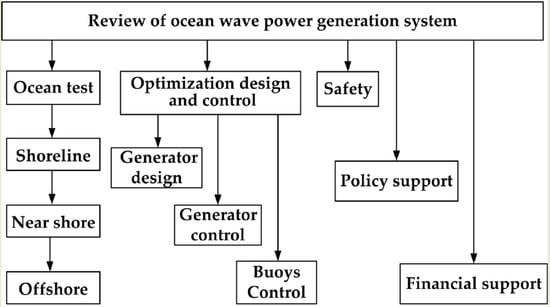
1. Introduction
2. Ocean Wave Power Generation System Tests
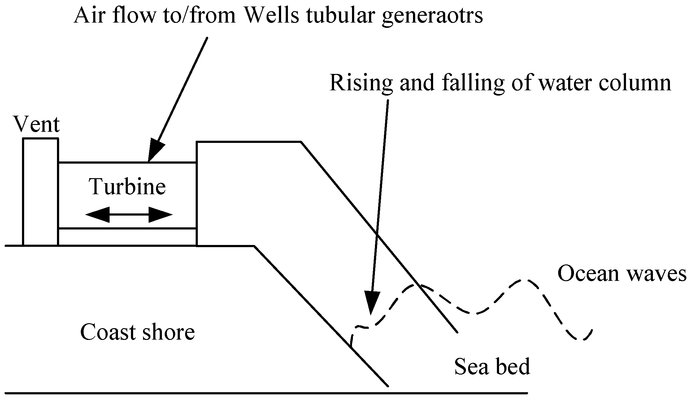
2.1. Tested in the Shoreline
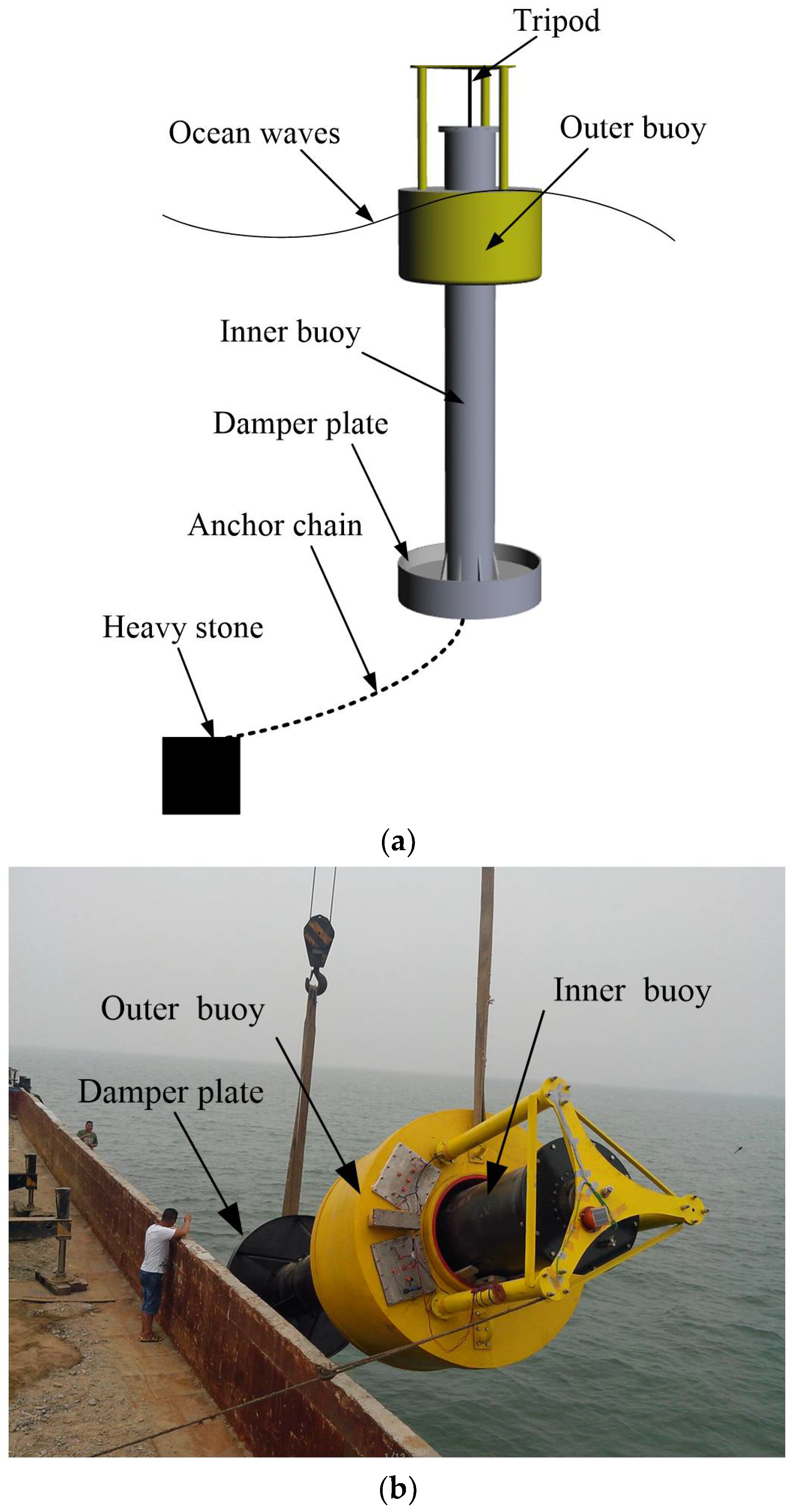
2.2. Tested near the Shore
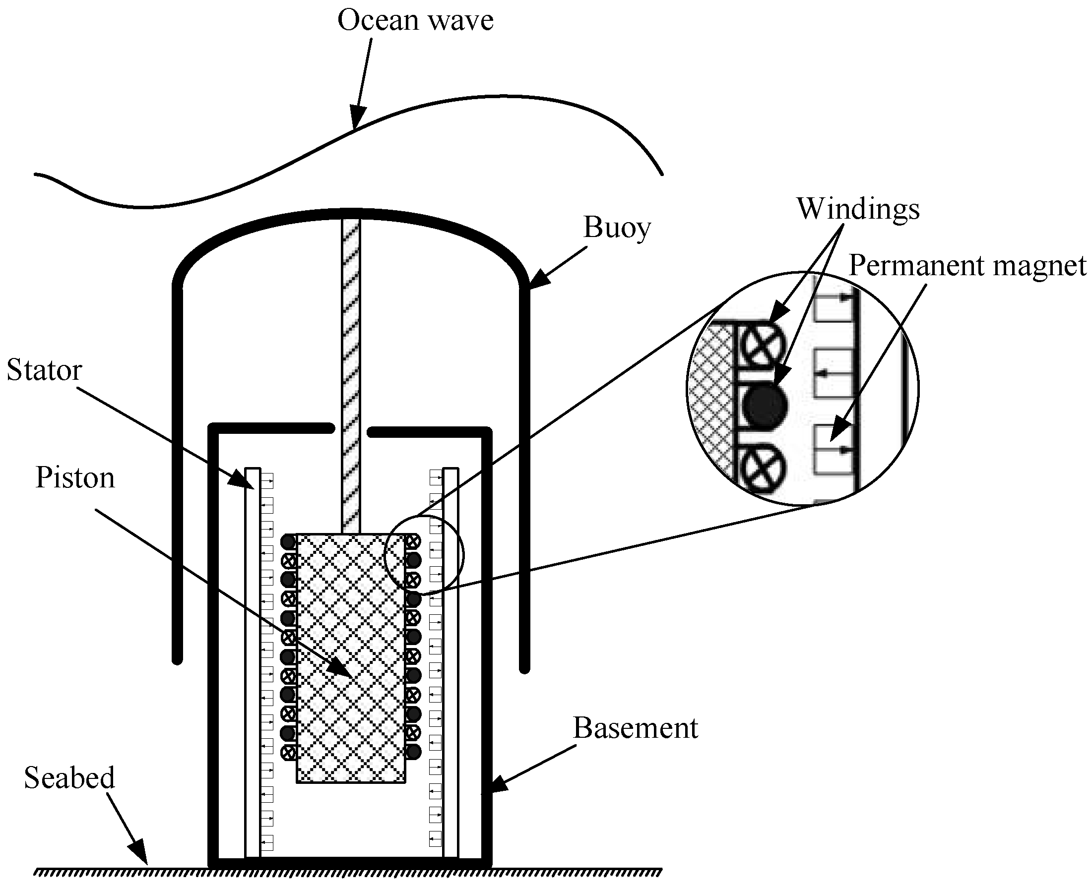
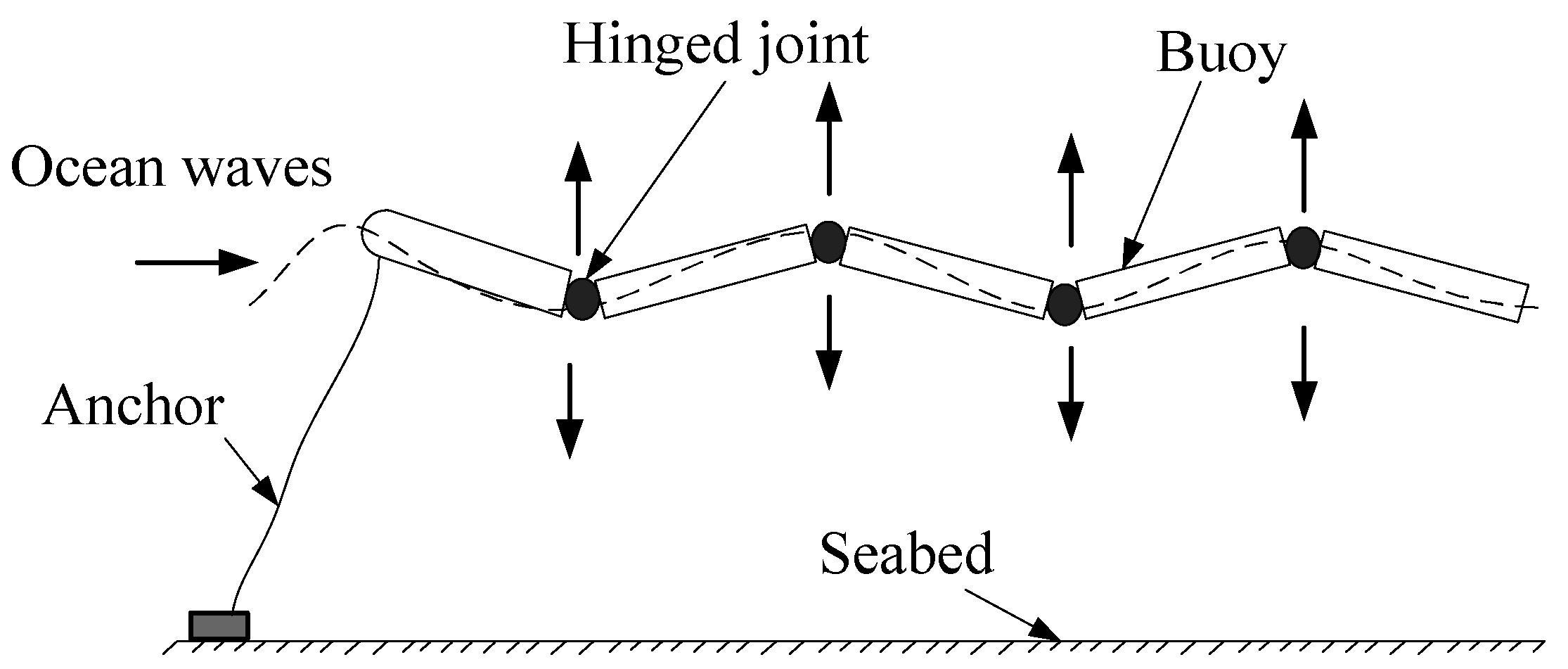
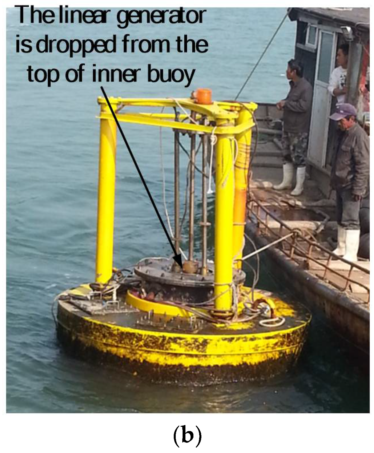
2.3. Tested Offshore
3. Optimal Design of Linear Generator for Ocean Wave Power Generation System
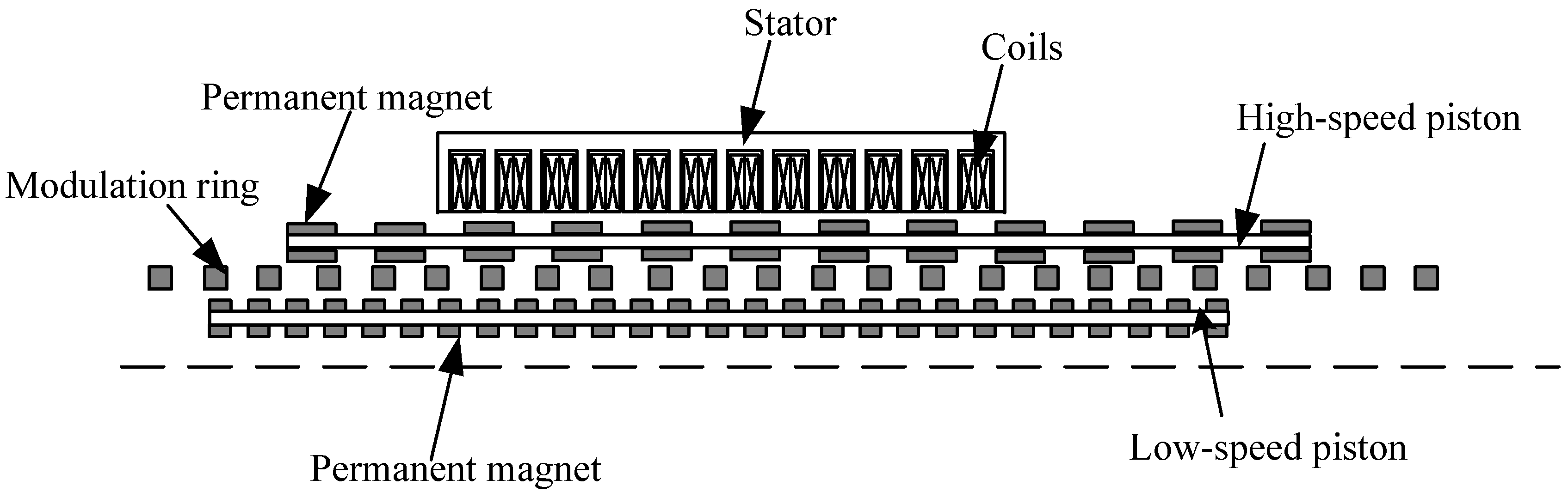
3.1. Linear Magnetic-Geared Generator
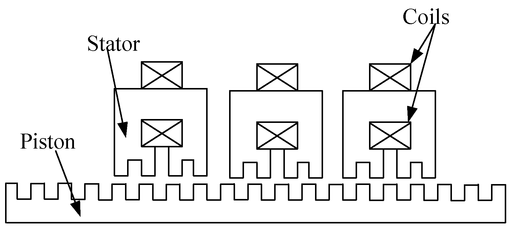
3.2. Linear Switched Reluctance Generator
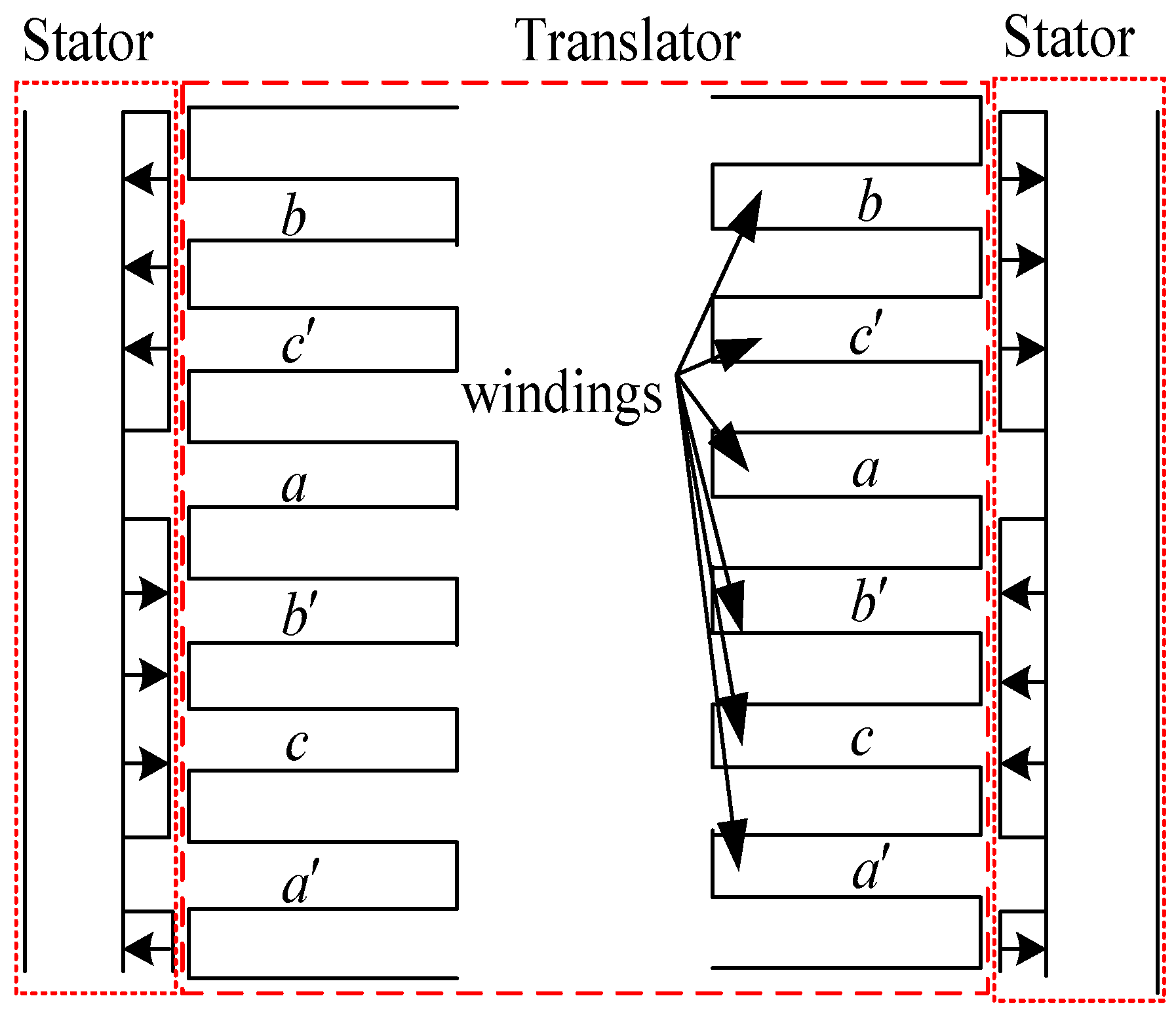
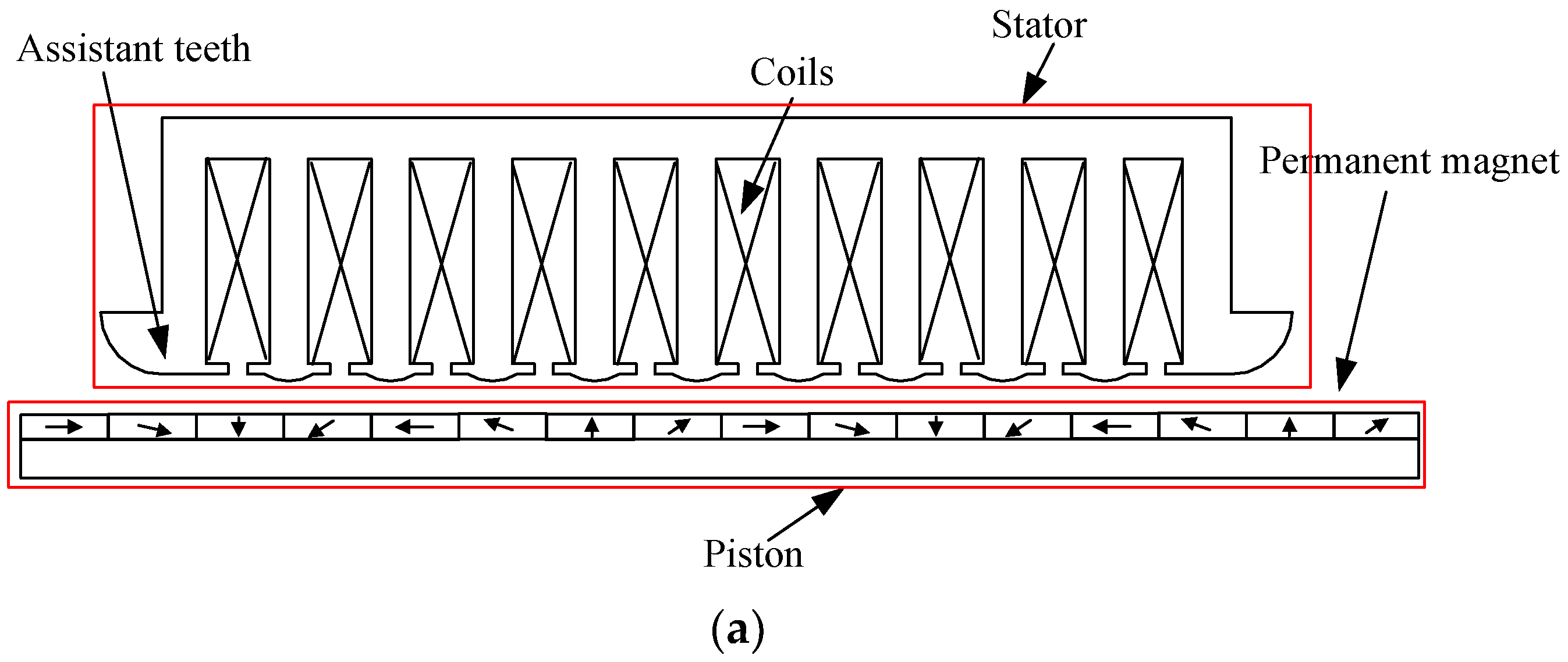
3.3. Halbach Magnetized Linear Permanent Magnet Generator
4. Optimization Control Methods for Ocean Wave Power Generation System
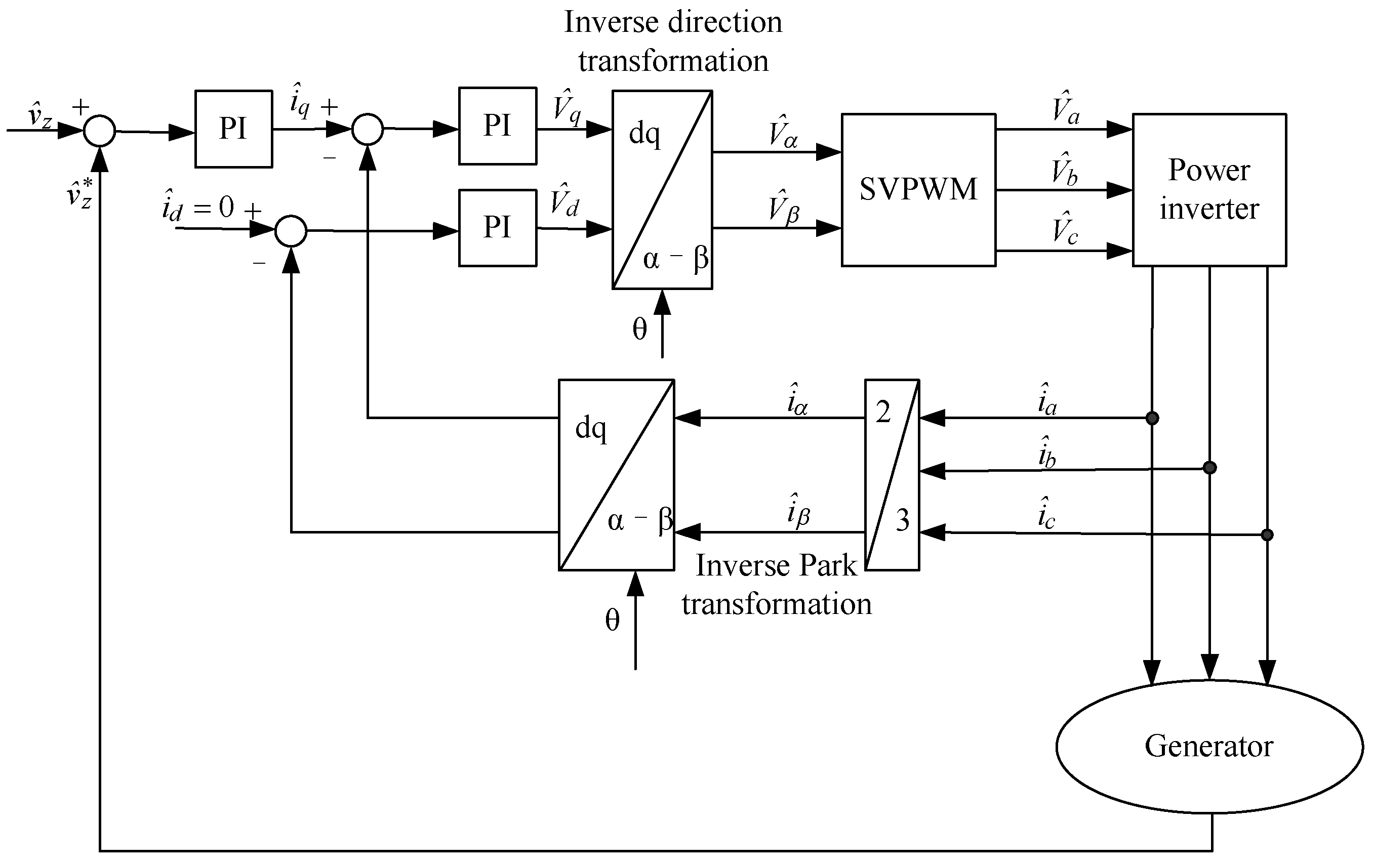
4.1. Optimization Control of Generator
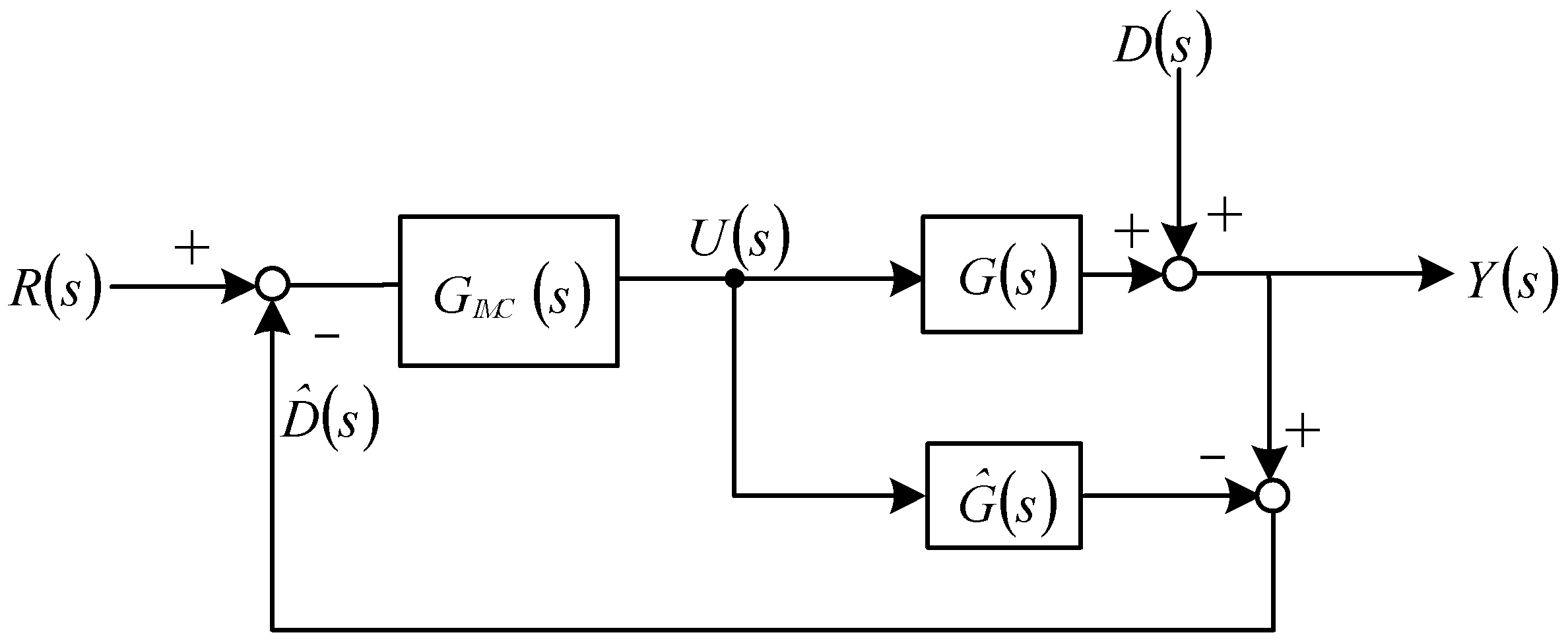
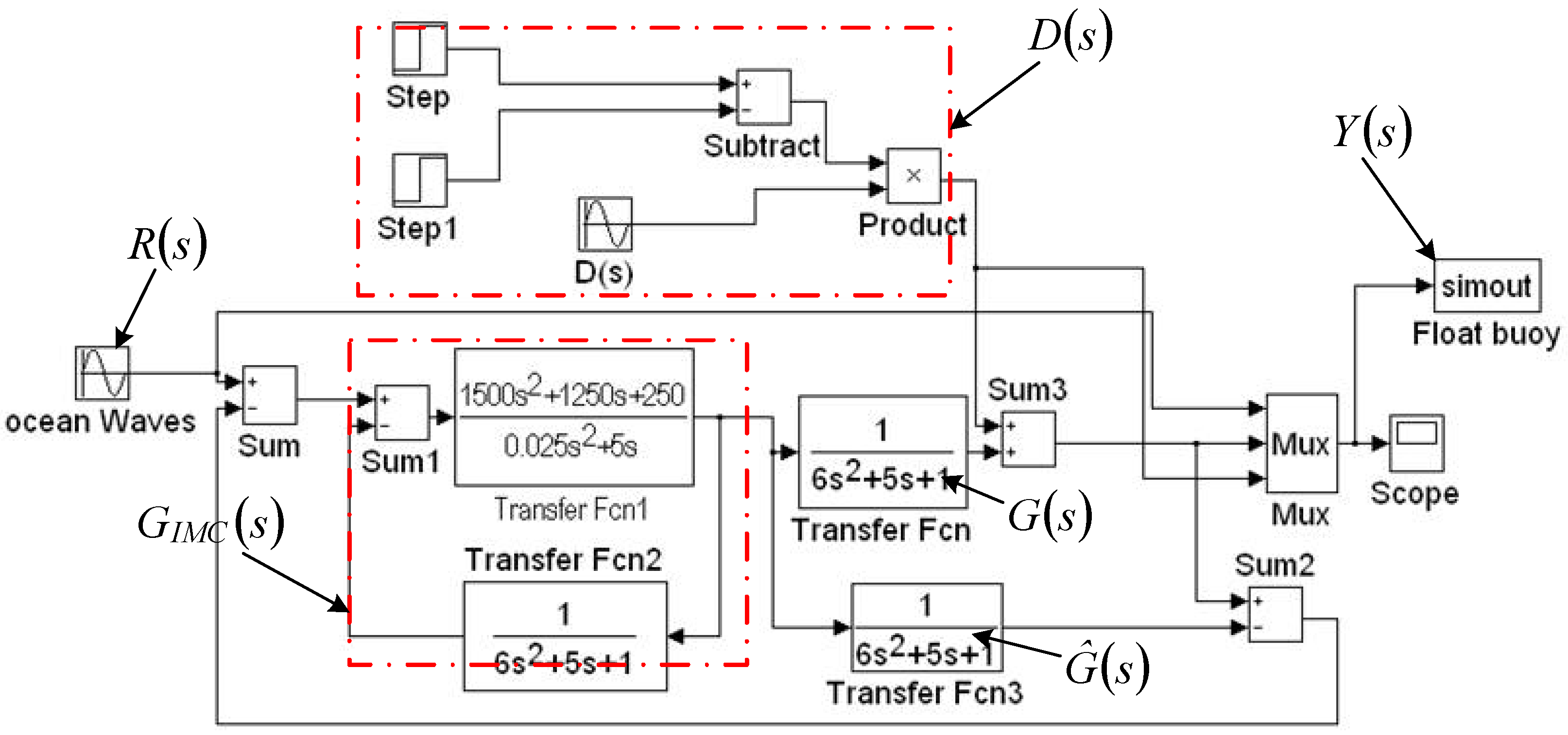
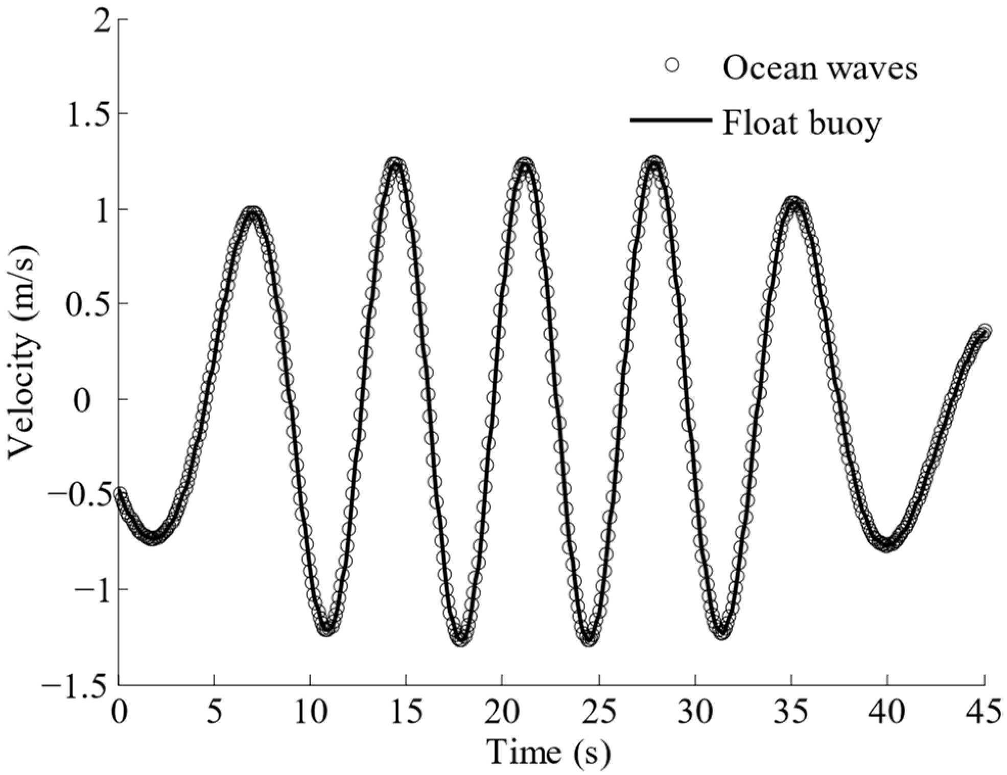
4.2. Optimization Control of Float Buoy
5. Safety of Ocean Wave Power Generation Systems in Ocean Waves
6. Policy and Financial Support for Ocean Wave Power Generation
7. Conclusions
Author Contributions
Funding
Institutional Review Board Statement
Informed Consent Statement
Data Availability Statement
Acknowledgments
Conflicts of Interest
References
- Wang, S.M.; Li, Z.Y.; Yu, T.; Ma, C.B. A review of research on multi-energy complementary ocean energy integrated power generation technology. Mar. Sci. Bull. 2019, 38, 241–249. [Google Scholar]
- Khan, N.; Kalair, A.; Abas, N.; Haider, A. Review of ocean tidal, wave and thermal energy technologies. Renew. Sustain. Energy Rev. 2017, 72, 590–604. [Google Scholar] [CrossRef]
- Gradowski, M.; Gomes, R.P.F.; Alves, M. Hydrodynamic optimisation of an axisymmetric floating Oscillating Water Column type wave energy converter with an enlarged inner tube—ScienceDirect. Renew. Energy 2020, 162, 1519–1532. [Google Scholar] [CrossRef]
- Currie, M. Hydrogen, Fuel Cells and the Optimisation of the LIMPET 500 on Islay. Master’s Thesis, University of Strathclyde Glasgow, Glasgow, UK, 2002. [Google Scholar]
- Falcão, A.F.O. Wave energy utilization: A review of the technologies. Renew. Sustain. Energy Rev. 2010, 12, 899–918. [Google Scholar] [CrossRef]
- Ning, D.Z.; Wang, R.Q.; Zou, Q.P.; Teng, B. An experimental investigation of hydrodynamics of a fixed OWC Wave Energy Converter—Science Direct. Appl. Energy 2016, 168, 636–648. [Google Scholar] [CrossRef]
- Heath, T.V. A review of oscillating water columns. Philos. Trans. R. Soc. A 2012, 370, 235–245. [Google Scholar] [CrossRef] [PubMed]
- Rizal, A.M.; Ningsih, N.S. Ocean wave energy potential along the west coast of the Sumatra island, Indonesia. J. Ocean. Eng. Mar. Energy 2020, 6, 137–154. [Google Scholar] [CrossRef]
- Abanades, J.; Greaves, D.; Iglesias, G. Wave farm impact on beach modal state. Mar. Geol. 2015, 361, 126–135. [Google Scholar] [CrossRef]
- Lin, L.; Yu, H. Offshore wave energy generation devices: Impacts on ocean bio-environment. Acta Ecol. Sin. 2012, 32, 117–122. [Google Scholar] [CrossRef]
- Özkop, E.; Sharaf, A.; Altaş, İ.H. An adaptive fuzzy PI controlled bus quantity enhancer for wave energy systems. Turk. J. Electr. Eng. Comput. Sci. 2016, 24, 2454–2468. [Google Scholar] [CrossRef]
- Oikonomou, C.L.; Gomes, R.P.; Gato, L.M. Unveiling the potential of using a spar-buoy oscillating-water-column wave energy converter for low-power stand-alone applications. Appl. Energy 2021, 292, 116835. [Google Scholar] [CrossRef]
- Huang, W.; Yang, J. A Novel Piecewise Velocity Control Method Using Passivity-Based Controller for Wave Energy Conversion. IEEE Access 2020, 8, 59029–59043. [Google Scholar] [CrossRef]
- Hong, Y.; Pan, J.; Liu, Y.; Wang, C.; Li, C.; Fu, P. A Review on Linear Generator Based Wave Energy Conversion Systems. Proc. CSEE 2019, 39, 1886–1899. [Google Scholar]
- Abraham, E.; Kerrigan, E.C. Optimal active control and optimization of a wave energy converter. IEEE Trans. Sustain. Energy 2013, 4, 324–332. [Google Scholar] [CrossRef]
- Trivedi, K.; Koley, S. Mathematical modeling of breakwater-integrated oscillating water column wave energy converter devices under irregular incident waves. Renew. Energy 2021, 178, 403–419. [Google Scholar] [CrossRef]
- Ahmed, N.; Mueller, M. Impact of varying clearances for thewWells turbine on heat transfer from electrical generators in oscillating water columns. In Proceedings of the IEEE International Conference and Exhibition on Ecological Vehicles and Renewable Energies, Monte Carlo, Monaco, 27–30 March 2013; pp. 1–6. [Google Scholar]
- Ren, Y.; Zhao, J.; Qin, C.; Zhu, L. Small signal stability analysis and optimal control of AWS based wave energy conversion system. In Proceedings of the 12th IEEE PES Asia-Pacific Power and Energy Engineering Conference (APPEEC), Nanjing, China, 20–23 September 2020. [Google Scholar]
- Beiro, P.; Valério, D.; Costa, J. Linear model identification of the archimedes wave swing. In Proceedings of the International Conference on Power Engineering, Energy and Electrical Drives, Setubal, Portugal, 12–14 April 2007; pp. 660–665. [Google Scholar]
- Wahyudie, A.; Jama, M.; Susilo, T.B.; Mon, B.F.; Shaaref, H.; Noura, H. Design and Testing of a Laboratory Scale Test-rig for Wave Energy Converters using a Double-sided Permanent Magnet Linear Generator. IET Renew. Power Gener. 2017, 11, 922–930. [Google Scholar] [CrossRef]
- Edwards, K.; Mekhiche, M. Ocean power technologies powerbuoy: System-level design, development and validation methodology. In Proceedings of the 2nd Marine Energy Technology Symposium, Seattle, WA, USA, 15–18 April 2014. [Google Scholar]
- Reddy, K.S.; Prajwal, K.S.; Satwik, T.S. A review on the gradiation towards pelamis wave energy converter. In Proceedings of the 4th International Conference on Trends in Electronics and Informatics (ICOEI), Tirunelveli, India, 15–17 June 2020. [Google Scholar]
- Chen, Z.; Yu, H.; Hu, M.; Meng, G.; Wen, C. A review of offshore wave energy extraction system. Adv. Mech. Eng. 2013, 5, 623020. [Google Scholar] [CrossRef]
- Chen, Z.; Yu, H.; Liu, C.; Hong, L. Design, Construction and Ocean Testing of Wave Power generation system with Permanent Magnet Tubular Linear Generator. Trans. Tianjin Univ. 2016, 22, 72–76. [Google Scholar] [CrossRef]
- Azhari, B.; Wijaya, F.D.; Yazid, E. Performance of Linear Generator Designs for Direct Drive Wave Energy Converter under Unidirectional Long-Crested Random Waves. Energies 2021, 14, 5098. [Google Scholar] [CrossRef]
- Liu, C.; Rui, D.; Zhu, H.; Fu, W. Multi-Physical Coupling Field of a Permanent Magnet Linear Synchronous Generator for Wave Energy Conversion. IEEE Access 2021, 9, 85738–85747. [Google Scholar] [CrossRef]
- Feng, N.; Yu, H.; Hu, M.; Liu, C.; Huang, L.; Shi, Z. A Study on a Linear Magnetic-Geared Interior Permanent Magnet Generator for Direct-Drive Wave Energy Conversion. Energies 2016, 9, 487. [Google Scholar] [CrossRef]
- García-Tabarés, L.; Lafoz, M.; Blanco, M.; Torres, J.; Obradors, D.; Nájera, J.; Navarro, G.; García, F.; Sánchez, A. New Type of Linear Switched Reluctance Generator for Wave Energy Applications. IEEE Trans. Appl. Supercond. 2020, 30, 5207105. [Google Scholar]
- Zhao, S.; Chen, H.; Nie, R.; Liu, J. Multi-objective optimal design of double-sided switched reluctance linear generator for wave power generation. COMPEL 2019, 38, 1948–1963. [Google Scholar] [CrossRef]
- Huang, X.; Lin, Z.; Xiao, X. Four-quadrant force control with minimal ripple for linear switched reluctance machines. CES Trans. Electr. Mach. Syst. 2020, 4, 27–34. [Google Scholar] [CrossRef]
- Qiu, L.; Shi, Y.; Pan, J.; Zhang, B.; Xu, G. Collaborative Tracking Control of Dual Linear Switched Reluctance Machines Over Communication Network With Time Delays. IEEE Trans. Cybern. 2017, 47, 4432–4442. [Google Scholar] [CrossRef]
- Liu, C. Research on the Tubular Permanent Magnet Linear Generator Using Direct-Driven Wave Power Take-Off System. Ph.D. Thesis, Southeast University, Nanjing, China, 2015. [Google Scholar]
- Talaat, M.; Sedhom, B.E.; Hatata, A.Y. A new approach for integrating wave energy to the grid by an efficient control system for maximum power based on different optimization techniques. Int. J. Electr. Power Energy Syst. 2021, 128, 106800. [Google Scholar] [CrossRef]
- Guo, B.; Ringwood, J. Non-Linear Modelling of a Vibro-Impact Wave Energy Converter. IEEE Trans. Sustain. Energy 2021, 12, 492–500. [Google Scholar] [CrossRef]
- Zabihi, M.; Mazaheri, S.; Namin, M.M.; Mazyak, A.R. Irregular wave interaction with an offshore OWC wave energy converter. Ocean. Eng. 2021, 222, 108619. [Google Scholar] [CrossRef]
- Falnes, J. Ocean Waves and Oscillating Systems; Cambridge University Press: Cambridge, MA, USA, 2002. [Google Scholar]
- Bariša, T.; Sumina, D.; Kutija, M. Control of generator-and grid-side converter for the interior permanent magnet synchronous generator. In Proceedings of the International Conference on Renewable Energy Research and Applications, Palermo, Italy, 22–25 November 2015; pp. 1015–1020. [Google Scholar]
- Xu, Q.; Li, N.L.; Xu, Y. Flutter Control of the Wind Turbine Blade Based on IMC-PID Control. Measurement & Control Technology. Meas. Control. Technol. 2017, 36, 70–73. [Google Scholar]
- Chen, Z.; Yu, H.; Wen, C. An Optimal Control Method for Maximizing the Efficiency of Direct Drive Ocean Wave Energy Extraction System. Sci. World J. 2014, 2014, 480916. [Google Scholar] [CrossRef][Green Version]
- Marei, M.I.; Mokhtar, M.; El-Sattar, A.A. MPPT strategy based on speed control for AWS-based wave energy conversion system. Renew. Energy 2015, 83, 305–317. [Google Scholar] [CrossRef]
- Tri, N.M.; Truong, D.Q.; Binh, P.C.; Dung, D.T.; Lee, S.; Park, H.G.; Ahn, K.K. A novel control method to maximize the energy-harvesting capability of an adjustable slope angle wave energy converter. Renew. Energy 2016, 97, 518–531. [Google Scholar] [CrossRef]
- Kim, J.; Cho, I.H.; Kim, M.H. Numerical calculation and experiment of a heaving-buoy wave energy converter with a latching control. Ocean. Syst. Eng. 2019, 1, 1–19. [Google Scholar]
- Shadman, M.; Avalos, G.O.G.; Estefen, S.F. On the power performance of a wave energy converter with a direct mechanical drive power take-off system controlled by latching. Renew. Energy 2021, 169, 157–177. [Google Scholar] [CrossRef]
- Davidson, J.; Ringwood, J.V. Ringwood Mathematical Modelling of Mooring Systems for Wave Energy Converters—A Review. Energies 2017, 10, 666. [Google Scholar] [CrossRef]
- Amaechi, C.V.; Chesterton, C.; Butler, H.O.; Wang, F.; Ye, J. Review on the design and mechanics of bonded marine hoses for Catenary Anchor Leg Mooring (CALM) buoys. Ocean. Eng. 2021, 242, 110062. [Google Scholar] [CrossRef]
- Penalba, M.; Giorgi, G.; Ringwood, J.V. Mathematical modelling of wave energy converters: A review of nonlinear approaches. Renew. Sustain. Energy Rev. 2017, 78, 1188–1207. [Google Scholar] [CrossRef]
- Giorgi, G.; Penalba, M.; Ringwood, J. Nonlinear hydrodynamic models for heaving buoy wave energy converters. In Proceedings of the Asian Wave and Tidal Energy Conference, Singapore, 25–27 October 2016. [Google Scholar]
- Amaechi, C.V.; Wang, F.; Ye, J. Mathematical Modelling of Bonded Marine Hoses for Single Point Mooring (SPM) Systems, with Catenary Anchor Leg Mooring (CALM) Buoy Application—A Review. J. Mar. Sci. Eng. 2021, 9, 1179. [Google Scholar] [CrossRef]
- Kalogirou, A.; Bokhove, O. Mathematical and numerical modelling of wave impact on wave-energy buoys. In Proceedings of the International Conference on Ocean, Offshore and Arctic Engineering, Busan, Korea, 19–24 June 2016. [Google Scholar]
- Doyle, S.; Aggidis, G.A. Development of multi-oscillating water columns as wave energy converters. Renew. Sustain. Energy Rev. 2019, 107, 75–86. [Google Scholar] [CrossRef]
- Lehmann, M.; Karimpour, F.; Goudey, C.A.; Jacobson, P.T.; Alam, M.R. Ocean wave energy in the United States: Current status and future perspectives. Renew. Sustain. Energy Rev. 2017, 74, 1300–1313. [Google Scholar] [CrossRef]
- Zhang, X.; Zhang, P. Comparative Analysis of Domestic and Overseas Current Marine Energy Policies. Mar. Econ. 2018, 8, 48–56. [Google Scholar]
- European Ocean Energy Association. Oceans of Energy—European Ocean Energy Roadmap 2010–2050. Strategy International Communications, Belgium. 2010. Available online: https://www.icoe-conference.com/publication/oceans_of_energy_european_ocean_energy_roadmap_2010_2050/ (accessed on 21 December 2021).
- Hemer, M.A.; Manasseh, R.; McInnes, K.L.; Penesis, I.; Pitman, T. Perspectives on a Way Forward for Ocean Renewable Energy in Australia. Renew. Energy 2018, 127, 733–745. [Google Scholar] [CrossRef]
- Park, J.I.; Kim, T. Institutional improvement measures for environmental assessment in the pursuit of eco-friendly ocean renewable energy development in South Korea. Renew. Sustain. Energy Rev. 2016, 58, 526–536. [Google Scholar] [CrossRef]
- Wu, X.D.; Chen, G.Q. Energy and water nexus in power generation: The surprisingly high amount of industrial water use induced by solar power infrastructure in China. Appl. Energy 2017, 195, 125–136. [Google Scholar] [CrossRef]


| Reference Number | Main Research Contents |
|---|---|
| Reference [25] | Structure comparison of iron-cored linear permanent magnet generator and semi iron-cored linear permanent magnet generators |
| Reference [26] | Analysis of multi-physical coupling field of a permanent magnet linear synchronous generator |
| Reference [27] | Analysis of air gap flux density, thrust force characteristics, no-load and load performances of linear magnetic-geared interior permanent magnet generator |
| References [28,29] | Multi-objective optimization design and simulation calculation of linear switched reluctance generator |
| References [30,31] | Structure and operational control of linear switched reluctance machines |
| Reference Number | Main Research Contents |
|---|---|
| References [33,34,35,36] | Overall system optimization control of ocean wave power generation system, including the power output, transmission and grid connection, etc. |
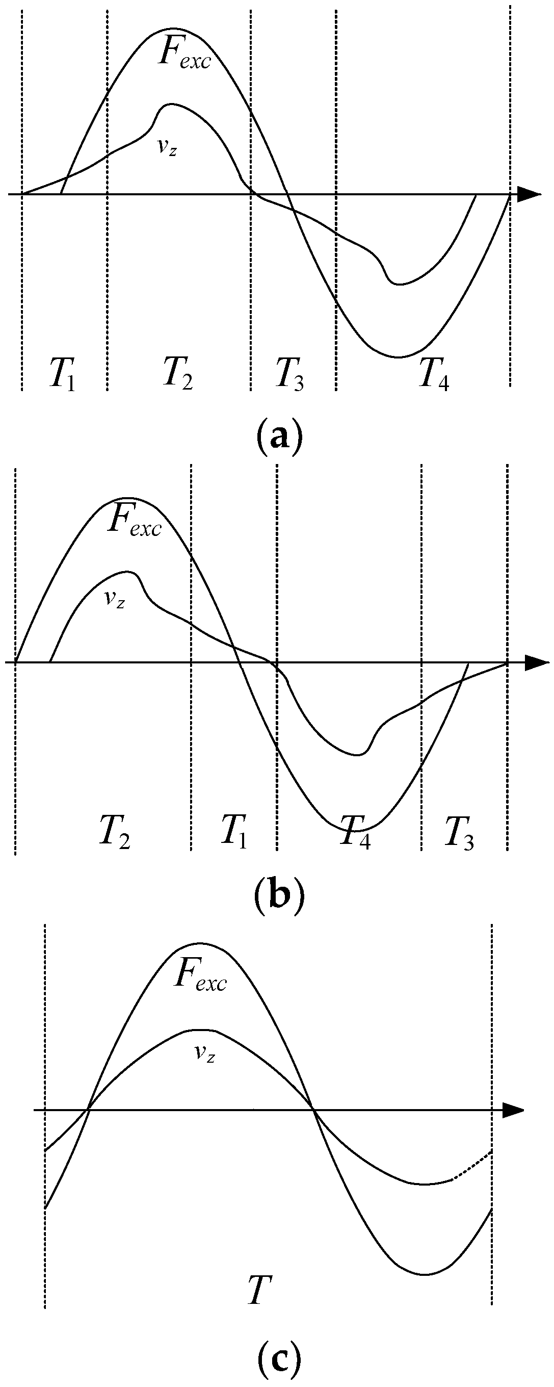
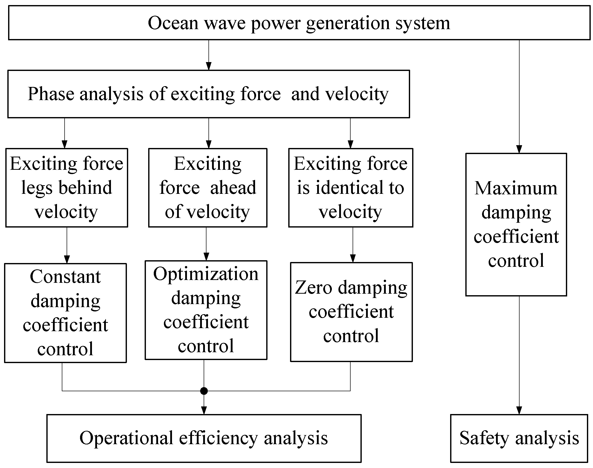
| Reference [37] | Analysis of the forces that exert on ocean wave power generation system. |
| References [38,39] | Q-axis current control of linear generator for the stable operational and maximum power output of ocean wave power generation system. |
| Reference [40] | Optimization control of float buoy to improve the power output of ocean wave power generation system. |
| References [41,42,43] | Other optimization control methods—such as maximum power point tracking (MPPT), learning vector quantitative neural network (LVQNN), and latching control—to improve the power output of ocean wave power generation system, but still in the stage of theoretical research. |
Publisher’s Note: MDPI stays neutral with regard to jurisdictional claims in published maps and institutional affiliations. |
© 2021 by the authors. Licensee MDPI, Basel, Switzerland. This article is an open access article distributed under the terms and conditions of the Creative Commons Attribution (CC BY) license (https://creativecommons.org/licenses/by/4.0/).
Share and Cite
Wang, J.; Chen, Z.; Zhang, F. A Review of the Optimization Design and Control for Ocean Wave Power Generation Systems. Energies 2022, 15, 102. https://doi.org/10.3390/en15010102
Wang J, Chen Z, Zhang F. A Review of the Optimization Design and Control for Ocean Wave Power Generation Systems. Energies. 2022; 15(1):102. https://doi.org/10.3390/en15010102
Chicago/Turabian StyleWang, Juanjuan, Zhongxian Chen, and Fei Zhang. 2022. "A Review of the Optimization Design and Control for Ocean Wave Power Generation Systems" Energies 15, no. 1: 102. https://doi.org/10.3390/en15010102
APA StyleWang, J., Chen, Z., & Zhang, F. (2022). A Review of the Optimization Design and Control for Ocean Wave Power Generation Systems. Energies, 15(1), 102. https://doi.org/10.3390/en15010102