Article

Impact of Geometry of Toothed Segments of the Innovative KOMTRACK Longwall Shearer Haulage System on Load and Slip during the Travel of a Track Wheel

1
Faculty of Mechanical Engineering and Robotics, AGH University of Science and Technology, Mickiewicza 30 Av., 30-059 Kraków, Poland
2
Division of Machines and Equipment, KOMAG Institute of Mining Technology, Pszczyńska 37 Street, 44-101 Gliwice, Poland
*
Author to whom correspondence should be addressed.
Energies 2021, 14(9), 2720; https://doi.org/10.3390/en14092720
Submission received: 6 April 2021 / Revised: 5 May 2021 / Accepted: 5 May 2021 / Published: 10 May 2021
(This article belongs to the Special Issue The IMTech 2021 Innovative Mining Technologies)

Abstract

:
Longwall shearers operating in the underground mine workings move along the longwall face along the conveyor troughs. The haulage system, which is made up of two kinematic pairs in the form of track wheels installed in shearer movers, cooperating with the toothed route built in the conveyor’s throughs, is responsible for moving the shearer. The currently used solutions of longwall shearers’ haulage systems do not ensure proper cooperation of the track wheels with toothed segments, which results in failures and breakdowns in the operation of the longwall systems, causing significant financial losses. Rigid solution of the gear components used is the reason. The solution of the flexible toothed segment, allowing it to adapt to the longitudinal and transverse curvature of the AFC (armored face conveyor) route during cooperation with the track wheel, was developed as part of the research project jointly implemented by KOMAG Institute of Mining Technology, AGH University of Science and Technology, Łukasiewicz Research Network–Cracow Institute of Technology, Specodlew Innovative Foundry Company and Polish Mining Group Inc., co-financed by the European Regional Development Fund (contract no. POIR.04.01.04-00-0068/17). The general design and principle of operation of the suggested KOMTRACK system is given. The results of the comparative simulations and analyses are presented. The load and slip values during the cooperation of the track wheels with the standard and new suggested toothed segment were estimated. The effectiveness of cooperation in the shearer movement along a disturbed conveyor route was also compared.

1. Introduction

Proper functioning of a longwall shearer system requires, among other things, using efficient shearer haulage systems. The main task of the haulage system is to move the longwall shearer along the panel, overcoming the movement resistance and the resistance resulting from the mining and loading [1] of coal onto the conveyor. There are many factors that significantly affect mining machines’ availability and the daily output [2], and the operation of the haulage system is among them. Operational reliability of the haulage system depends on the availability time of the mining machine and the daily production. In work [3], the authors, analyzing the causes of breakdowns in the longwall system haulage, state the failures of the haulage system as one of the main reasons for downtimes related to the replacement of worn-out driving wheels and trapping shoes. In the works [4,5,6,7,8,9,10,11], the longwall shearer haulage systems used in the world in underground coal mines were reviewed.
The analysis of the possibility of increasing the production clearly indicates the need to use increasingly efficient longwall systems equipped with the shearers of high technical parameters. This applies to the power installed in the shearer, its weight, the haulage speed, and the pulling force. An increase in operational parameters of longwall shearers is also followed by modifications to the haulage system. The modifications concern the haulage systems, developed nearly forty years ago, intended for use in the shearers of much lower power and pulling force. Since then, there have been no significant changes or new solutions to this type of haulage systems. The review of world literature allowed us to find only a few articles dealing with this subject [12,13,14,15,16]. Most of the items, which mention the haulage systems of longwall shearers, are in Polish.
The stringless haulage mechanism with two driving wheels known as Eicotrack 2 BP, the model of which is shown in Figure 1 [17,18,19], is the most commonly used system in underground coal mines. In this system, the shearer is moved due to the cooperation of track wheels, located vertically in the shearer movers, with the Eicotrack linear rack installed horizontally in the spill-plate. The linear rack segment used in this system consists of two longitudinal bars, inseparably connected with six pins, creating a rigid body.
During operation, the adjacent conveyor troughs move in the horizontal and vertical planes one against the other. Rigid fastening of rack segments to the spill-plates supports makes their movement impossible, especially in the horizontal plane, which causes the rack position to change in relation to the track wheel when the route of the AFC (armored face conveyor) is bent. This leads, on the one hand, to a disturbance of the pitch between the end pins of adjacent linear racks and to a change in the distance between the pins of the rack segments and the axis of rotation of the track wheel, and on the other hand, to the so-called teeth edging [1,2,3,4,5,6,7,8,9]. Unfavorable excesses of dynamic forces causing increased wear of the roadheader track wheel are a result of the above-mentioned route disturbance. In turn, as a result of the so-called teeth edging, the pressing stresses between the cooperating surfaces of the track wheel and rack are significantly exceeded, which also leads to excessive wear of the shearers’ track wheels. These phenomena are intensified along with the increasing power of movers and the weight of longwall shearers [20]. This is the reason for numerous downtimes during the longwall mining, leading to large losses due to the need to replace worn-out components in particularly dangerous conditions [21]. The view of damaged track wheels requiring replacement is shown in the Figure 2. In comparison to the new one, the dimensions of the teeth are up to 50% decreased.
In recent years, KOMAG has developed the concept of the innovative Flextrack haulage system, enabling the limitation of high pressing forces occurring in the Eicotrack system between the cooperating surfaces of the track wheel and the rack. Its flexibility reduces the change in the meshing ratio between neighboring segments, when the conveyor bends in the vertical and horizontal planes. The suggested system (Figure 3a) is fully compatible with the commonly used Eicotrack system, which guarantees its replaceability with the already existing longwall systems.
A rack consisting of segments containing only one tooth and two side walls symmetrical to the rack longitudinal axis is the essence of the innovative haulage system. Each of the sidewalls of the rack segment has spherical raceways, which are located on the cooperating surfaces of the successive rack segments. Such a design of cooperating components of the neighboring rack segments enables them to align with each other without changing the pitch between the successive teeth. The surfaces of the raceways of the successive segments of the rack have the possibility of transverse and longitudinal inclination, limited only by a special guide in which they are installed. Such a rack of the feed system allows overcoming, in a smooth way, the longitudinal and transverse bends of the AFC (armored face conveyor) route. The modular structure of the system will facilitate the assembly and replacement of each component of the haulage system. A profile with a concave, cylindrical side surface, the radius of which is 5% larger than the largest radius of the tooth profile of the driving wheel, has been suggested in a place of the convex tooth profile commonly used in the Eicotrack system. The outline of the tooth flank (Figure 3b) is a combination of the upper and lower convex surfaces located at the corners of the tooth and the concave central surface that connects them, cooperating with the gear tooth.
A prototype solution of this system was made and tested in the laboratory. The tests were carried out using a real longwall shearer in a work condition equal to the underground coal longwall. Their results confirmed the effectiveness of such a system (adaptation of rack segments to the curvature of the conveyor route). However, significant wear was still noticed in both the track wheels and the Flextrack toothed segments. The quantitative wear was about 20% higher than for the Eicotrack system, but it was very even. It is shown in Figure 4. There was a significant slip between the cooperating components; the frame wheel and the toothed segment were the reason for the increased wear. The encouraging results prompted the designers of the Flextrack system to develop a new version of the haulage system, allowing for the elimination or significant reduction of the slip and the load to the haulage system cooperating components.

2. Tests Scope and Objectives as Well as Used Methodology

The development of such a geometric version of the toothed segment so that during the cooperation of the track wheel with this segment, the maximum slip between the cooperating components is reduced was the objective of tests planned within the project. The effectiveness of this cooperation (adaptation of the track wheel plane to the axis of symmetry of the toothed segments) during the shearer’s movement along the curved route of the face conveyor as well as the loads generated in the case of the standard and new solution of the haulage system were also compared.
The first part describes the design and principle of operation of the suggested KOMTRACK haulage system. The developed new geometric versions of the gear segments were analyzed theoretically and simulated in terms of the slip formation. Successively, the impact of the rack profile shape on the gear ratio disturbances and slip speed were determined. The obtained research results allowed the selection of a geometric solution of the KOMTRACK rack segment, for which an additional analysis of the cooperation between the track wheel and the Type V3 gear segments in terms of slippage was made. The Type V3 toothed segment solution was checked and compared with the Eicotrack system in subsequent tests in terms of the effectiveness of cooperation on sections of the disturbed conveyor route and the loads recorded during this cooperation.
The planned tests were realized using the Autodesk Inventor–Dynamic Analysis Environment, Autodesk Simulation Mechanical, Excel, and ANSYS LS-DYNA software. They allowed for simulations in a very wide spectrum and with the highest accuracy. A high-power Z840 workstation, 120 GB RAM, and 2 × 20 cores were used for the tests. The following assumptions were made for the simulations:
  • the maximum force transmitted by a track wheel tooth was 562 kN for the KOMTRACK/Eicotrack system;
  • the angle of rotation of the KOMTRACK toothed segments in relation to each other was at least +/− 0.3 degrees;
  • the stresses at each point of cooperation of the friction pair—gear-racks were below the yield point of the material;
  • the KOMTRACK and Eicotrack haulage system pitch was 151 mm;
  • angular speed of the track wheel cooperating with racks was ω = 0.5 deg/s.
The simulation tests are described in detail in Section 4 and Section 5.

3. Design and Principle of Operation of the KOMTRACK System

The toothed segment, shown in Figure 5, is the main component of a new KOMTRACK haulage system, responsible for the power transmission and the shearer’s haulage. The toothed segments positioned successively in the guide form a kind of rack. Each segment contains one tooth bounded by sidewalls. Each of the walls has spherical-shaped raceways located on the cooperating surfaces of the successive rack segments. Sidewalls of the rack segment are finished on both sides with catches and sockets to catch neighboring rack segments. The components, cooperating with the neighboring components through spherical raceways, establish their mutual position without changing the tooth pitch. This ensures the correct operation of the gear-rack kinematic pair. The successively positioned segments of the rack enable transverse and longitudinal cooperation and overcoming bends of the conveyor route in vertical and horizontal directions (Figure 6).
The guide, which supports the skid of the shearer side gear, is another important component of the KOMTRACK haulage system. The guide task is to transfer the shearer gravity through its upper surface. Moreover, the guide is also a form of housing for the toothed segments placed therein. Figure 7 shows a 3D model of the shearer side gear with an installed skid and KOMTRACK system components. In the guides fixed to the conveyor troughs, segments are arranged, forming a rack that co-operates with the track wheel. The technology of assembly and disassembly of each toothed segment requires using the inspection window in the guide. The track wheel rolls over the successive toothed segments placed in the guides. The possibility of mutual displacement of the segments against each other enables the rack route to adapt to the armored face conveyor curvature.

4. Analysis of the Slippage of Track Wheel and KOMTRACK Toothed Segment

The operational conditions of the shearer drive are specific, which practically makes correct (from the theoretical point of view) cooperation between the wheel and rack impossible. In such a situation, we look for a compromise solution, such as non-standard profiles, which would make it possible to slow down the wear of the track wheel and thus extend its service life. This is due to two basic factors, namely the parameters of the pressure forces between the surfaces of the teeth of the wheel and rack and the slippage between these surfaces during the intermeshing process. This part of the article describes the analysis of the slip differences between the toothed surfaces of the track wheel and the new rack design.

4.1. Theoretical Analysis of the Correct Cooperation of the Gear—Rack System

When selecting a profile for teeth of cooperating components, properties of existing gears of the profiles, called standard ones, were analyzed. These include cycloidal and involute profiles as well as less frequently used circularly arched profiles.
The advantages of cycloidal gearing are as follows: the concave tooth surface of one-wheel cooperates with the convex surface of the tooth of the other wheel and vice versa; there is a wide contact area and small unit surface pressure; there is low tooth wear, low slippage, and high gearing efficiency. On the other hand, the disadvantages of cycloidal gearing are as follows: the need to maintain a very precise interaxial distance as the sum of the theoretical radii of the rolling wheels, teeth machining using precise numerically controlled machines, and vibrations and additional dynamic loads caused by inaccuracy of the tooth pitch.
Due to the above-mentioned disadvantages, the cycloidal gear cannot be considered to be used in the shearer drive. However, it is possible to try to use some of its features to modify the currently used involute gearing. Therefore, its properties should be analyzed, and the advantages and disadvantages, as well as the impact of parameters on the shaping of slips and loads, should be assessed.
The features of the involute profile are generally well known, as it is the most commonly used type of intermeshing in machine drives. It is also used in rack and pinion haulage drives of longwall shearers. In these drives, the track wheels are the involute teeth wheels, while the rack profiles are often modified. An attempt to apply a rack with a concave tooth profile (Flextrack system) to minimize the forces of inter-teeth pressures was not fully successful; therefore, a modification was aimed at minimizing the defects of involute intermeshing.
Contrary to the cycloidal profile, the involute profile is not very sensitive to the change of the distance between the axles of the cooperating wheels. However, this has other consequences, which are referred to as involute intermeshing disadvantages, the impact of which should be minimized by appropriate selection of parameters.
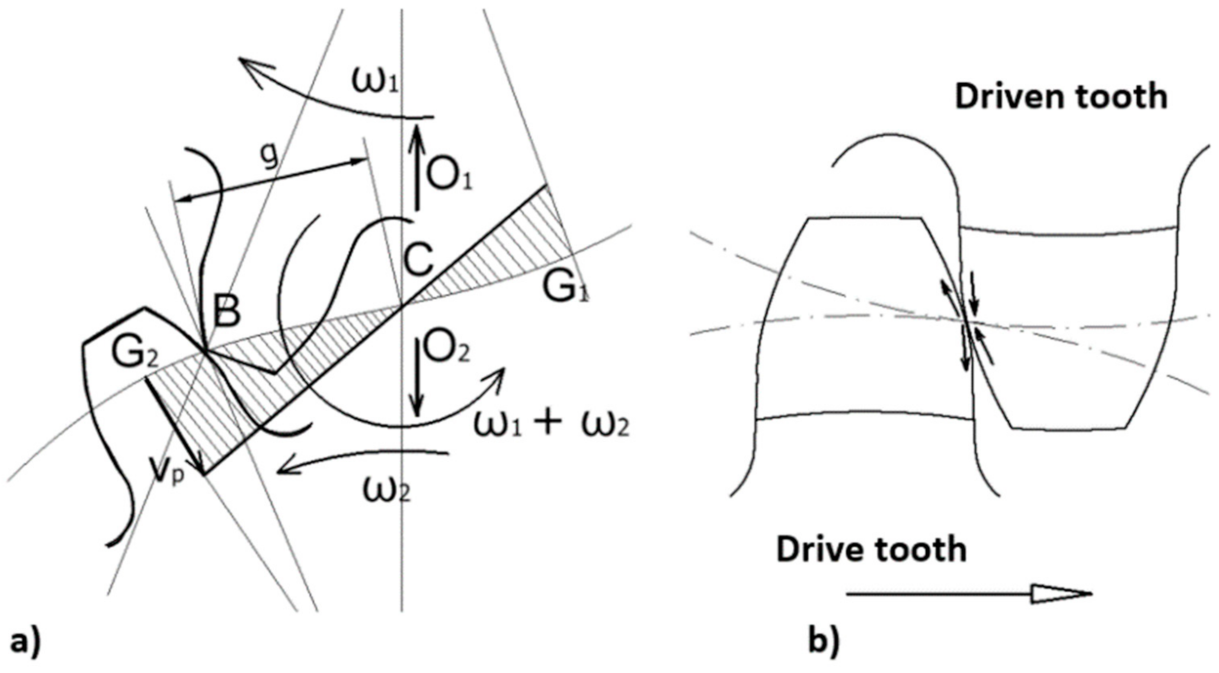
Complex rolling and sliding processes are found between the two involute sections in the buttress, in the result of different lengths of the cooperating involute sections. These sections responsible for the uniform rotations of the cooperating wheels can be regarded approximately as circular arcs, the radii of which are equal to the radii of curvature at the considered places. According to the diagram in Figure 8a, the slip speed vp at point B will be [22]:
vp = CB·(ω1 + ω2)
where:
  • ω1, ω2—angular speeds of cooperating gears,
  • CB = g—a distance of the discussed point B from the central point C.
The presented relationship shows that the slip speed is directly proportional to the segment g and to the sum of the angular speeds of the cooperating wheels. Assuming constant (unchanging) angular speeds, the greater the sliding speed, the greater the distance between the tooth side contact point and the central point C, equal to zero at point C. The sense of a slip speed vector on the tooth side surfaces is different on the tooth side of the driving wheel than on the tooth side of the driven wheel.
The method for determining the slip of the cooperating toothed wheels, presented in Figure 8, can be used to determine the slip of toothed gear. The method for determining the slip of the cooperating gears presented in Figure 8 can be used to determine the slip for a toothed gear. The situation is simplified because the rack is stationary, so only the rotational movement of the track wheel is considered, and the slip speed in this case will be g·ω1.
Conclusions regarding the selection of intermeshing parameters can be drawn from the presented analyses allowing for reduction of the slip, which have a significant impact on the wear of the track wheel teeth, especially in their tips. Unfortunately, it shows that the bigger slip causes the greater nominal angle of the profile and the lower high of the tooth. Additionally, this operation reduces intermeshing, which may lead to situations where loads are transferred by one tooth, especially when using the bigger tooth clearances, which is intentional due to the above-mentioned characteristics of the shearer driving gearbox. These features are reasonable when selecting the intermeshing parameters but should be confronted with the advantages and disadvantages of the involute intermeshing listed below.
The advantages of the involute gearing include the following: it is practically insensitive to changes in the distance between the axels of the cooperating wheels. Direction and magnitude of the radial pressures and along the buttress line (gearing) are constant, so there are no additional load fluctuations and vibrations during operation, and there is the relatively high efficiency of intermeshing, although, in the case of a shearer drive, this advantage is not evident due to the specific working conditions. The disadvantages, however, include the following: quite a large surface pressure, especially in the area of the teeth tips, and slightly greater slip than in the cycloidal intermeshing.
Despite these disadvantages, the involute gearing is the only basic solution that meets technical and economic criteria and, after modifying the profile of the rack teeth, will make it possible to reduce wear on the shearer track wheels [1,2,3,4,5,6,7,8,9].

4.2. Simulation Tests of the Slip during the Co-Operation of the Track Wheel and New Rack Solutions

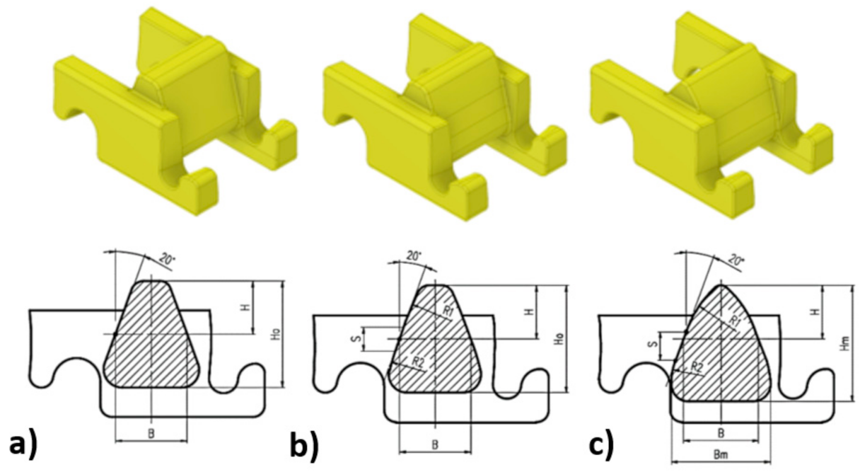
Considering the above information and the results of work with the Flextrack haulage system, three new design solutions for rack segments were developed for the simulation tests, Figure 9. The basic rack for involute intermeshing, i.e., a rack with straight teeth, is presented as Type V1 in Figure 9a. The following are racks with modified profiles. A segment with a tooth with a mixed arch profile Type V2 is shown in Figure 9b, and Type V3 in Figure 9c is a segment with a modified tooth profile, used in liner racks for the Eicotrack system manufactured by Ryfama.
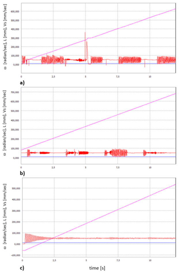
The results of simulation tests carried out in accordance with the suggested methodology in Autodesk Inventor-Dynamic Analysis Environment are shown in Figure 10. Three kinematic parameters, such as the angular speed of the frame wheel ω, assumed to be a constant (kinematic motion excitation), the displacement L of the model of the wheel drive, and the linear speed of this displacement Vs, are shown in graphs.
By comparing the diagrams, it is possible to assess the impact of the shape of the rack profile on disturbances in the gear ratio, mainly resulting from the slip between the teeth. This is precisely illustrated by the linear speed of displacement of the track wheel model of the drive Vs. In the case of the segment with a Type V3 tooth with a mixed arcuate profile, after the initial change of the speed, its stabilization can be observed. As for the two remaining segments, changes in the displacement speed are visible throughout the simulation. The impact of segment profiles on movement disturbances manifested as changes in the linear speed of displacement, assuming that the nature of periodically variable movements with variable amplitude is not stable. It can be concluded that the gaps between the teeth during intermeshing and disengagement of the gear teeth with the rack teeth have an impact on the process. Disturbances in the distance of the teeth increase the resistance to movement and pressure, and thus the friction forces at these moments. The type of profile and its geometrical parameters manifest themselves in periodic excitation of vibrations with variable amplitude.
The least favorable situation is in the case of the V1 straight-toothed rack, where these speed changes have the greatest dynamics, and therefore the most significant amplitude and duration. The load to the tips of the rack teeth, where there are the greatest pressures and at the same time the greatest slip, is important.
The situation is most favorable for teeth with a modified profile marked as Type V3. This is due to the fact that the modification of the profile mainly consisted in rounding the tooth head. The profile was modified with arcs of larger radii. Based on the presented diagrams, it can be assessed that the change of the rack profile causes that the gear ratio is not constant, irrespective of the impact of other factors, such as tooth clearances and changes in the distance between the rack wheel axis and the rack line. It should be emphasized that the presented simulation results are of comparative importance, and the conditions of the gear displacement and all parameters adopted for the simulation were identical for each case of the rack profile.
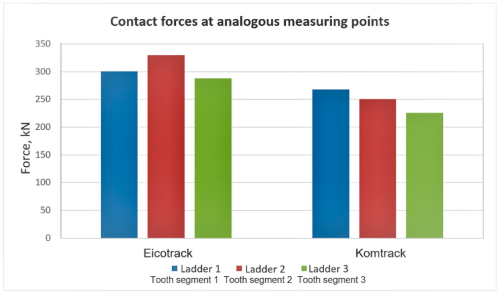
Regardless of the analysis of the impact of gear ratio disturbances, the result of which showed a significant improvement in the cooperation of the wheel with the rack by modifying the teeth geometry, the trajectory and speed of movement of the wheel tooth tips was also analyzed, enabling directly assessing the slip speed. Comparative analysis was also carried out regarding the tooth profile in the currently used Eicotrack rack system to verify the advisability of modifying the tooth profile of the rack. The parameters were determined in the same way as for the tests of racks suggested for the KOMTRACK system. The selected results of this analysis as screen shots are presented in Figure 11, Figure 12, Figure 13, Figure 14 and 
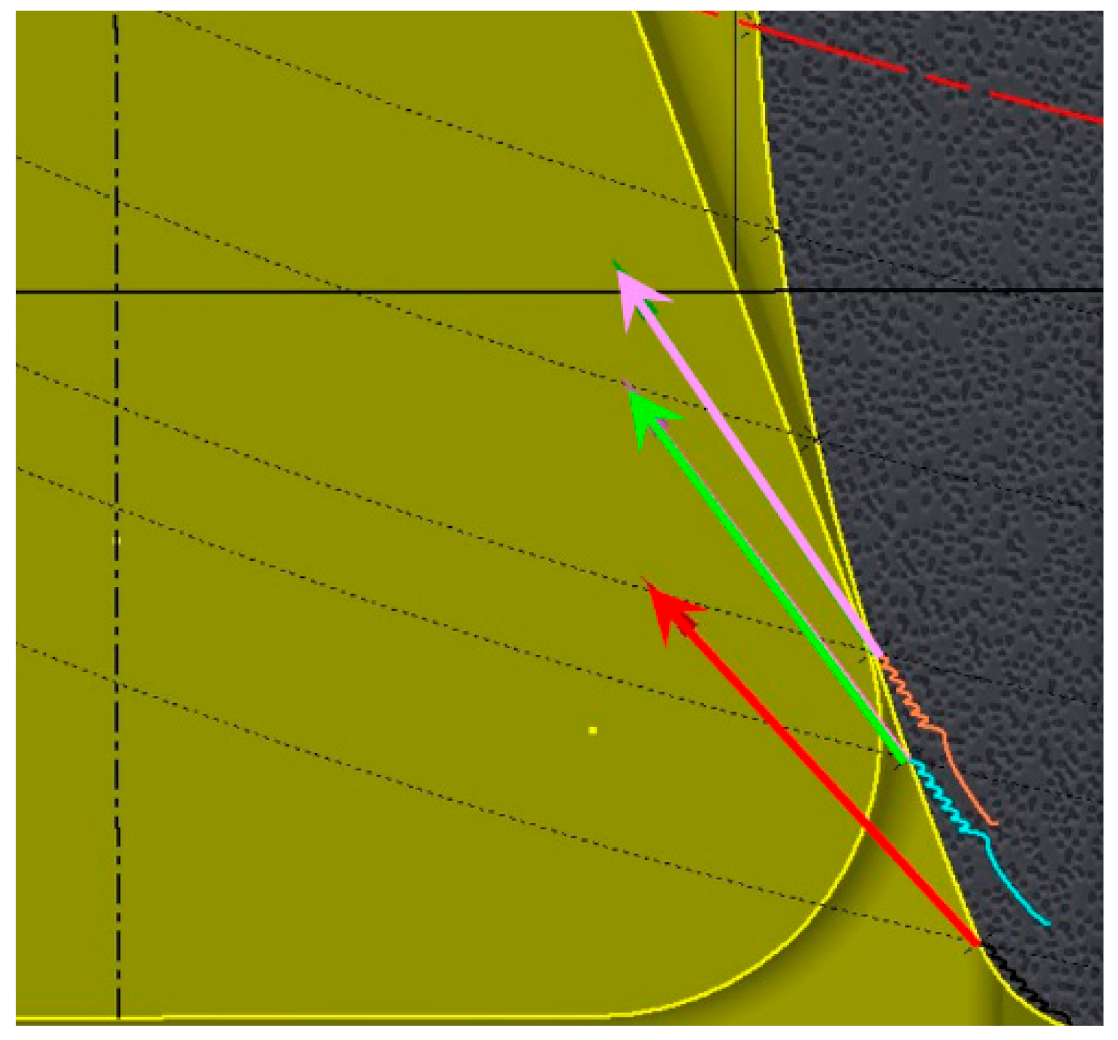
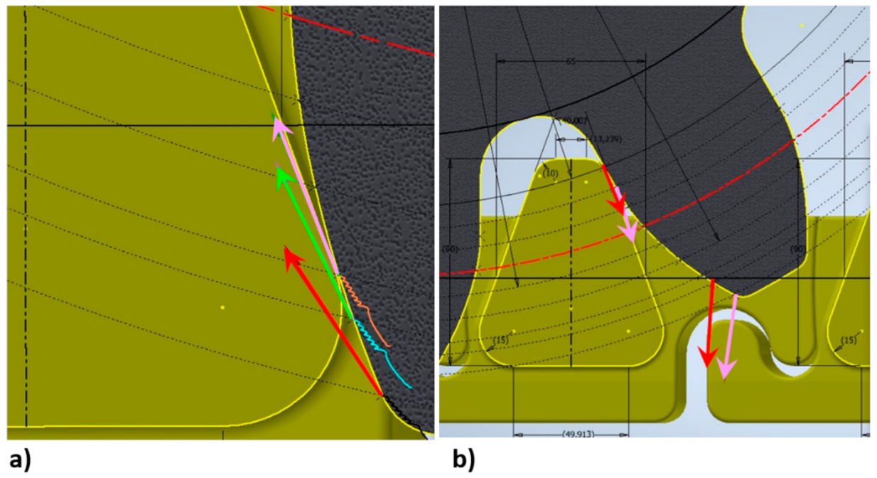
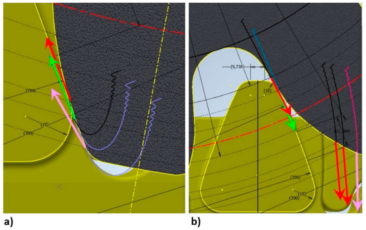
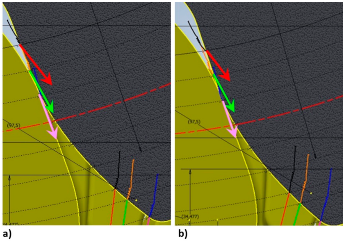
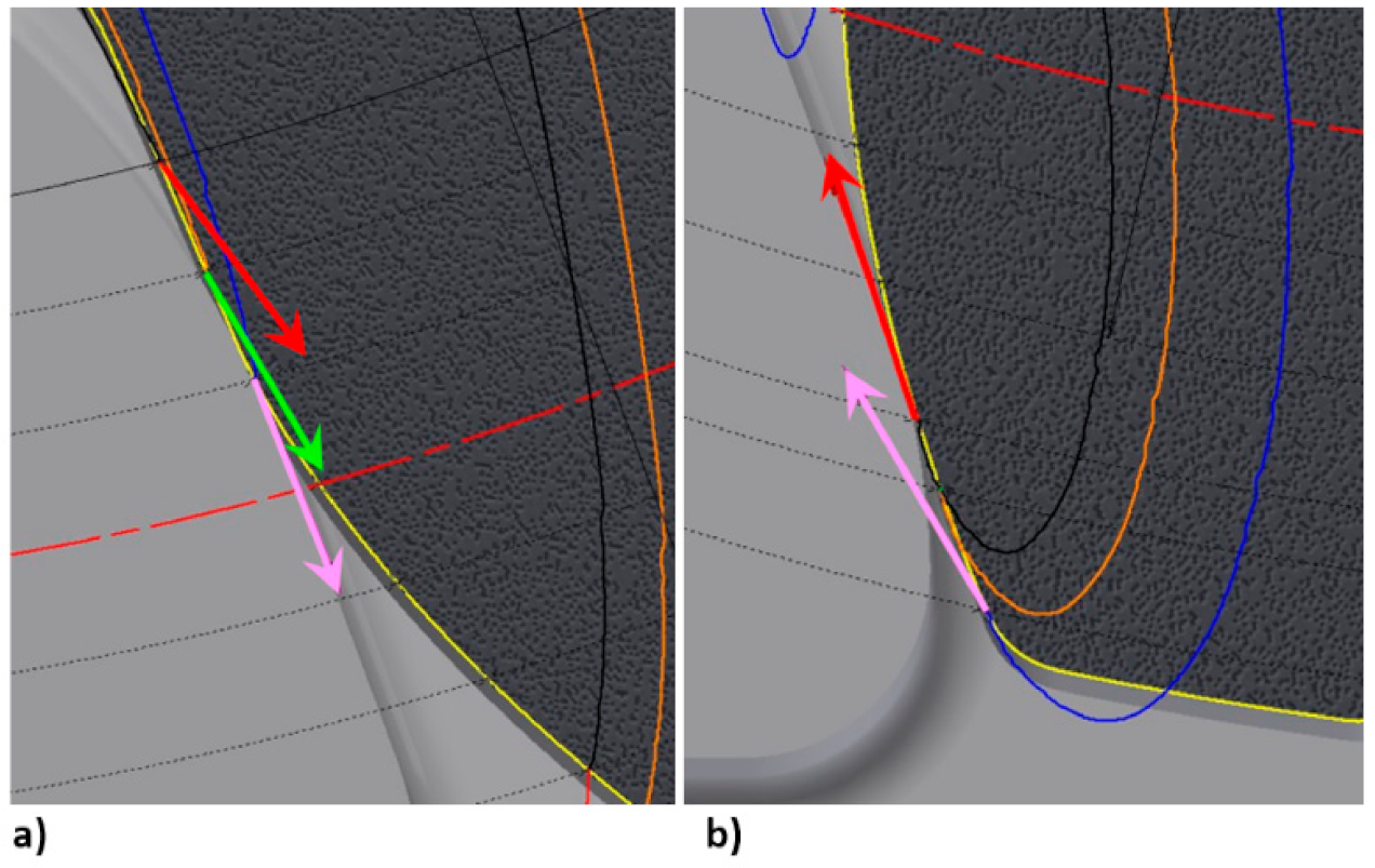
Figure 15, successively for each KOMTRACK rack segment and Eicotrack linear rack. The arrows show the values (length of the arrow) and directions of the slip speed for successive positions of the track wheel in relation to the rack—the first position is marked in red, the next in green, and the last in pink.
Figure 11 shows the situation before the track wheel enters the buttress with a rack, which is analogous for all analyzed cases. On the other hand, Figure 12 and Figure 13 show the situation of starting the slip process; the wheel enters the buttresses with Type V1 and V2 toothed gear, and in Figure 14 and Figure 15, the moment of starting the slip process when entering the buttress with toothed gears is shown for the Type V3 toothed gear and the Eicotrack linear rack, and slippage of the track wheel while moving over the rack surface is shown. The presented slip velocity vectors, marked in red, pink, and green in the Figures, are proportional to the values of these speeds.
When analyzing the cooperation between the track wheel of the involute profile of teeth and gears with the modified tooth profile, it can be stated that minor modifications that can be allowed to not deteriorate the cooperation of the gear-rack pair have a relatively small effect on the change in the value of slips. In a specific case, the variations in the slip range from 9.0 to 21.3 mm/s. These are approximate and comparative values, useful when selecting the direction of changes regarding the modification the rack tooth profile. It should be emphasized that the assumption that the profile of teeth of the track wheel cannot be changed imposes significant limitations in modification of the parameters of the toothed segment teeth profiles. It should be remembered that the specific operating conditions of the shearer haulage drive and its related structure and the need to accept large manufacturing tolerances and tooth clearances do not allow for the unverified application of the principles resulting from the theory of toothed gear operation.
It should be noted that a reduction in slips causes a reduction of the intermeshing surface area. In the analyzed case, the best result was obtained for the version of the rack profile marked as Type V3. The cost of this is reduction in the contact surface area of the gear teeth cooperating with the rack, thus eliminating the areas near the apexes and near the tooth base from cooperation. This will have consequences such as the deterioration of the cooperation conditions as the teeth wear.
Analysis of the tooth profile of the rack, which was used in the modified version of the Komtrack system, led to the conclusion that by modifying the tooth profile, the slip can be reduced. However, it should be noted that this is the result of the theoretical analysis of cooperation, and that the reduction of slippage reduces the degree of coverage for intermeshing. Consequently, the risk that a single tooth is carrying a heavy load increase. In the case of the shearer drive, it cannot be ruled out that a single tooth will bear the entire load of the shearer, assuming high rack stiffness. Partition of the rack into segments reduces this risk by increasing its longitudinal flexibility. Therefore, the analysis of loads to teeth will be of the greatest importance, taking into account various conditions of the route configuration.
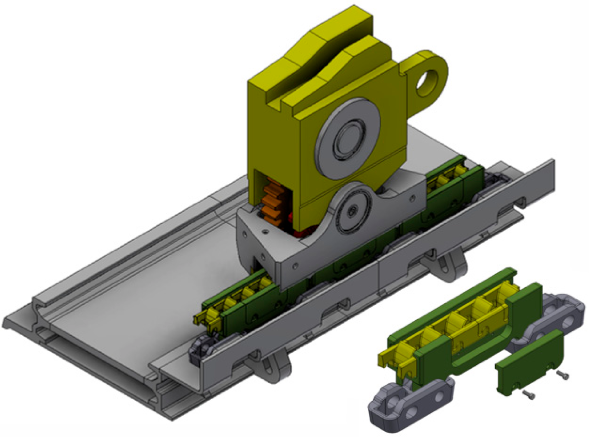
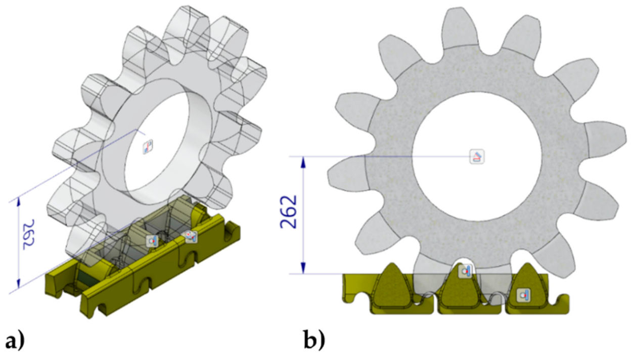
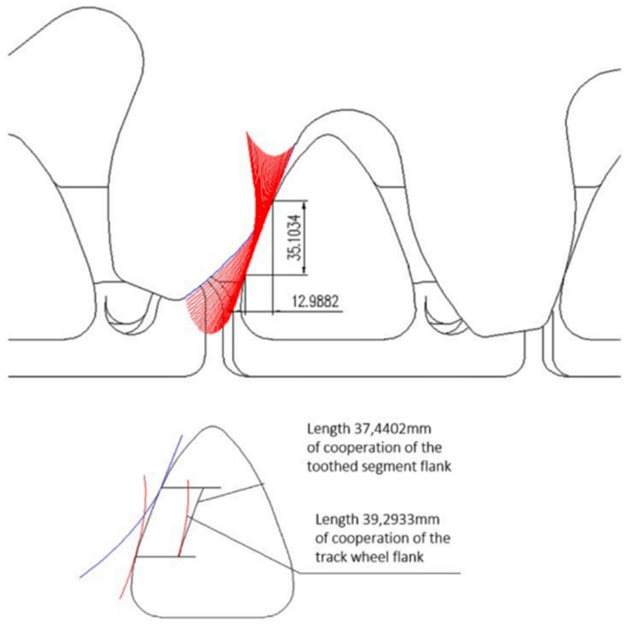
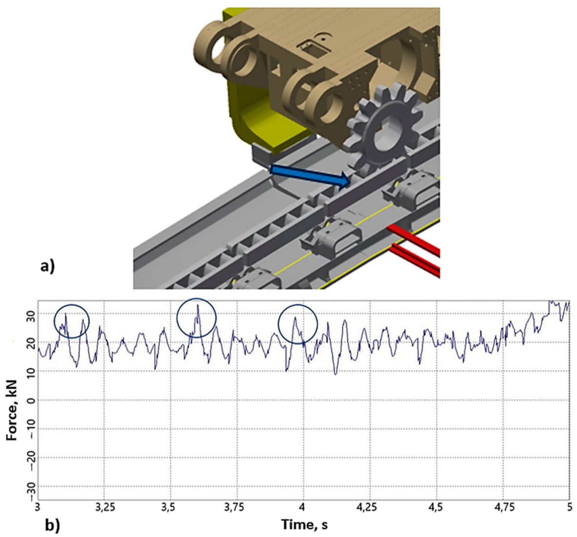
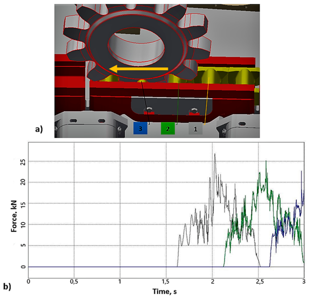
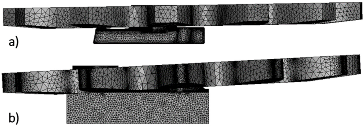
Later, the cooperation of the selected kinematic pair, the track wheel and the Type V3 gear segments, was analyzed in the Autodesk Inventor, AutoCAD Mechanical, and Microsoft Excel software environment in terms of slippage during the total rolling of the wheel through the toothed segment. Simplified 3D models of Type V3 toothed segments without casting beams and a simplified 3D model of a track wheel of a nominal width 76 mm was used for the analysis. For this type of analysis, only the profiles of the tooth flanks of the cooperating kinematic pairs are important. The entire length of the contact between the kinematic pair was analyzed, which translates into the angle of rotation of the track wheel by 30°. This angle results from the number of teeth on the frame wheel z = 12. After rotating the track wheel by 30°, the intermeshing conditions are repeated cyclically. The gear axis is 262 mm from the upper surface of the sidewalls of the gear segments. The general isometric view and the cross-section of the track wheel connection with toothed segments developed to analyze slips in the kinematic pair of the KOMTRACK feed system is shown in Figure 16.
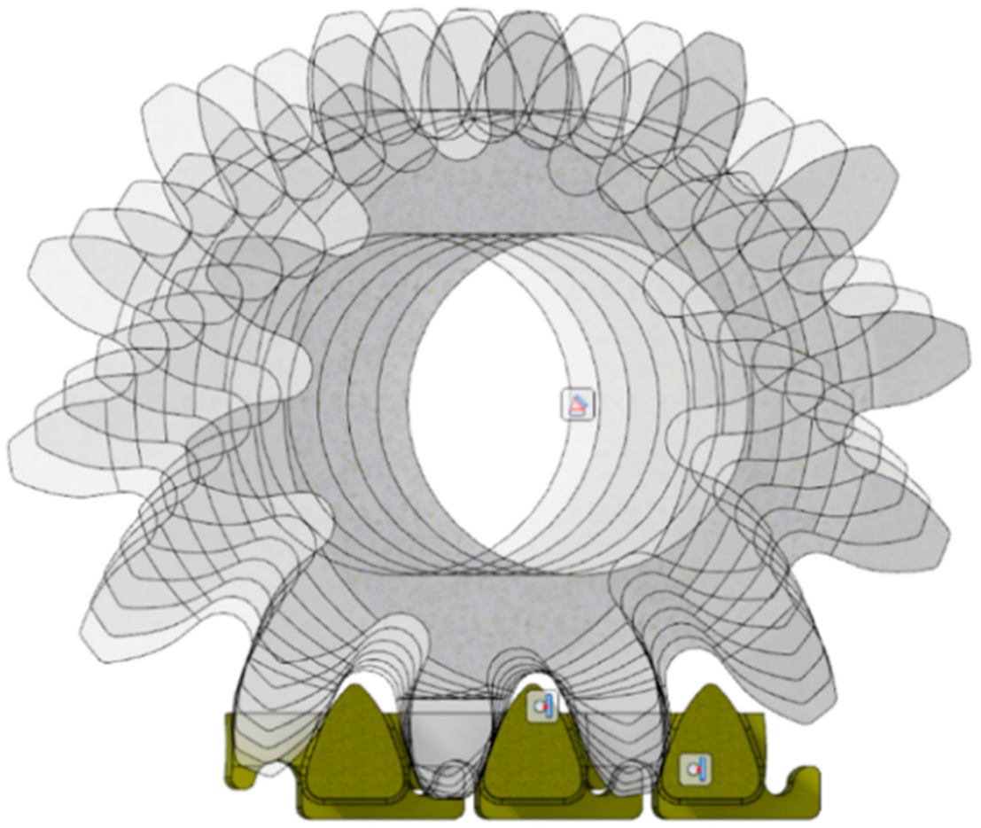
The analysis began with intermeshing at the moment when two teeth of the track wheel were in contact with two teeth of neighboring toothed segments. This intermeshing of the kinematic pair was taken as the beginning of the meshing and a track wheel rotation angle of 0° was assigned to it. Then the track wheel was rotated by 1° with the simultaneous contact of the corresponding tooth surfaces. Successive rotations of the track wheel by an angular increment of 1° were repeated until the wheel rotation by 30° was achieved. A view of the analyzed positions of the track wheel for the selected angular positions 0°, 5°, 10°, 15°, 20°, 25°, and 30° in relation to the toothed segments is given in Figure 17.
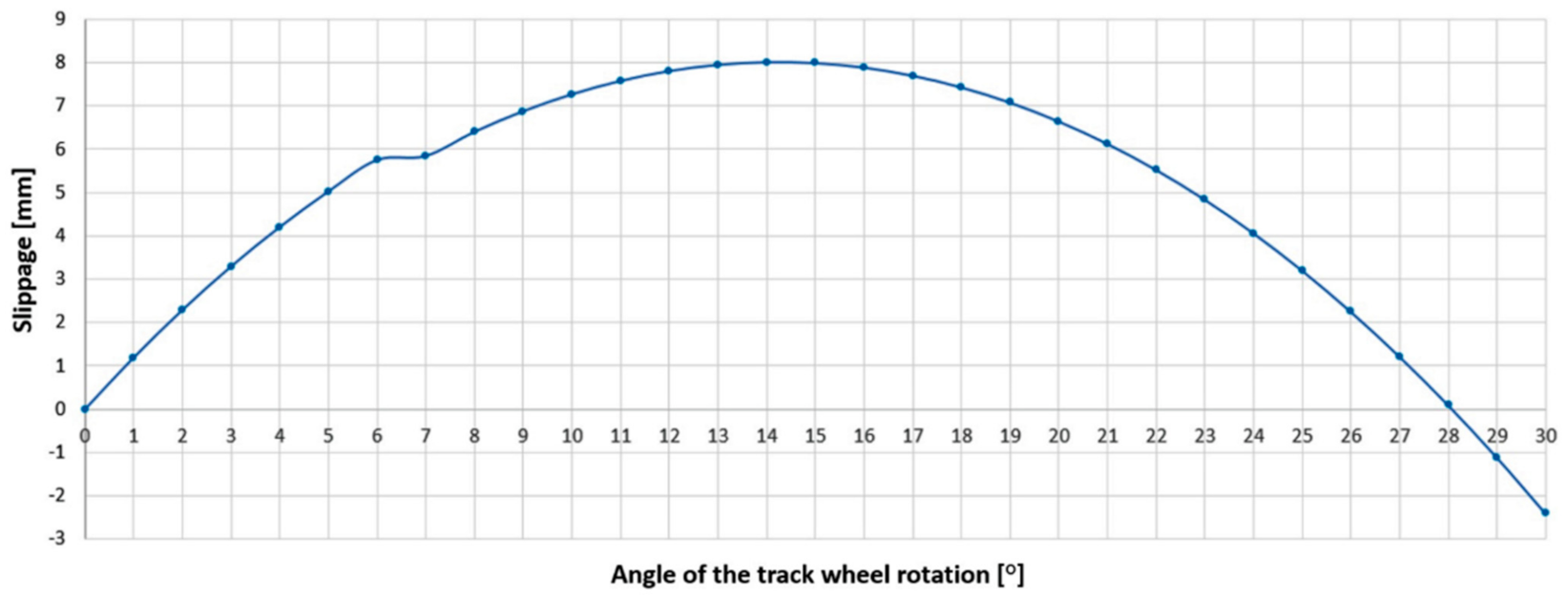
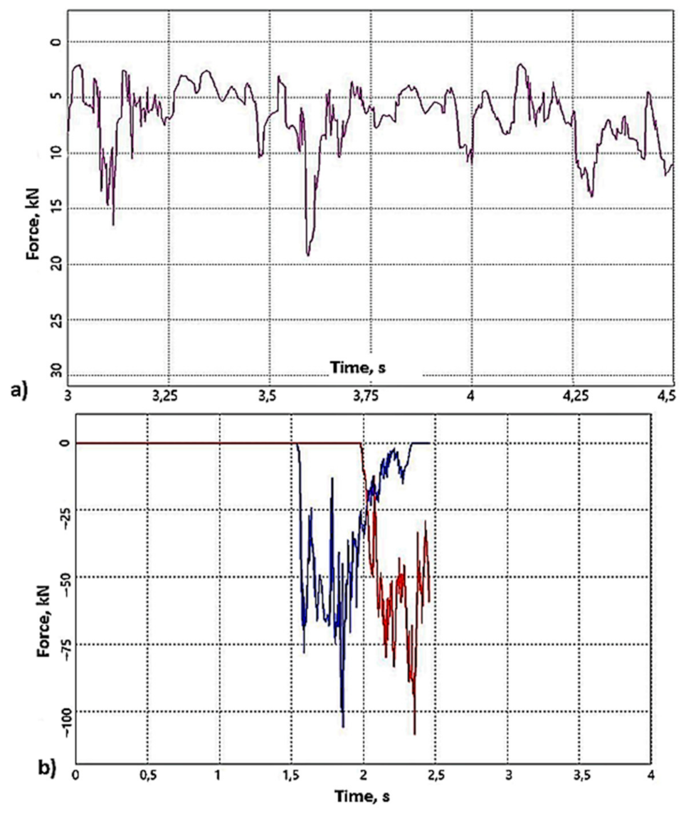
Figure 18 shows the results of the analysis of slippage of the track wheel flank in relation to the toothed segment flank. The study shows that starting from the moment of intermeshing, the slip of the toothed segment flank in relation to the track wheel flank increases, reaching a maximum value of about 8 mm in the middle of the intermeshing length (angle of rotation of the track wheel about 15°). Thereafter, the slip of the toothed segment flank decreases until it reaches a non-slip condition corresponding to a track wheel rotation angle of approximately 28°. From this moment until the gearing out, the flank of the track wheel begins to “accelerate” in relation to the flank of the toothed segment—slippage of the analyzed kinematic pair results from the differences in the active length of the cooperating teeth. The active length of the track wheel flank is approximately 39.3 mm, while the corresponding length of the toothed segment flank is less than 37.5 mm. The identified differences in the active length of the two buttress surfaces are one of the main causes of the frictional wear of the shearer’s haulage system components. Based on the determined slip, a diagram was drawn up (Figure 19), illustrating the changes depending on the track wheel angle of rotation.
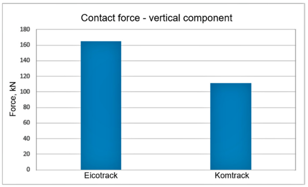
Based on the relationships given in [3], the pulling force, the meshing force, and the vertical component Y were also determined for the analyzed system. The obtained results are presented in the form of a graph for three consecutive intermeshings in Figure 20. The analysis of the results shows that for the angle of rotation of the track wheel in the range between the 7–20°, the traction force, and the vertical component Y remain at the same level. During one cycle of meshing, the pulling force increases, reaching its maximum value at the moment of gearing out.
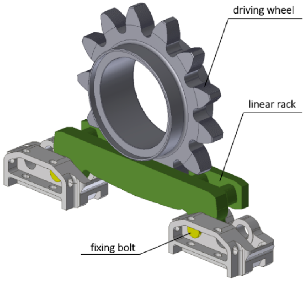
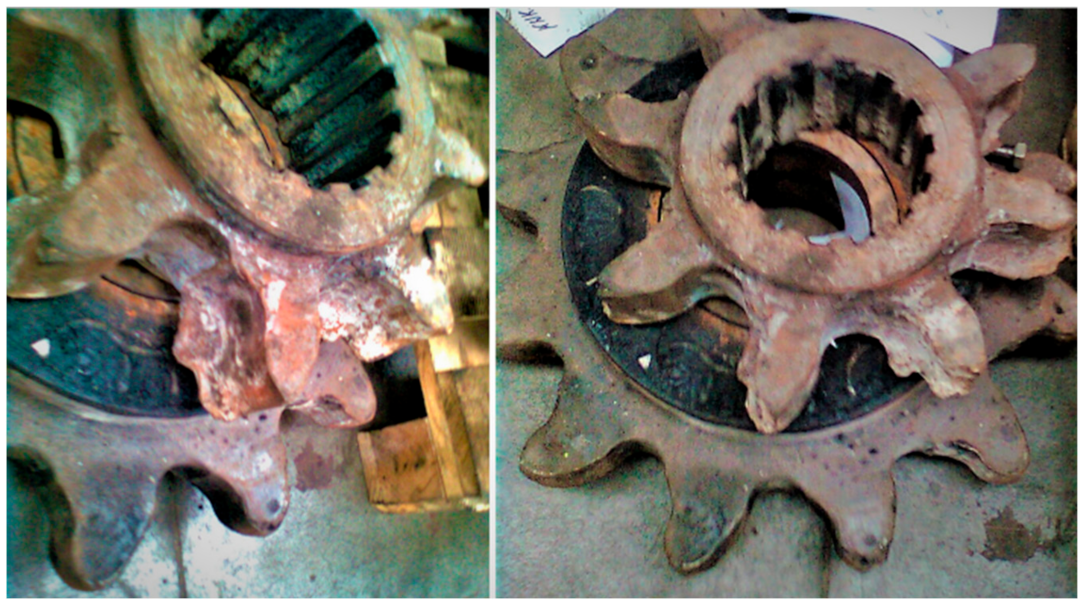
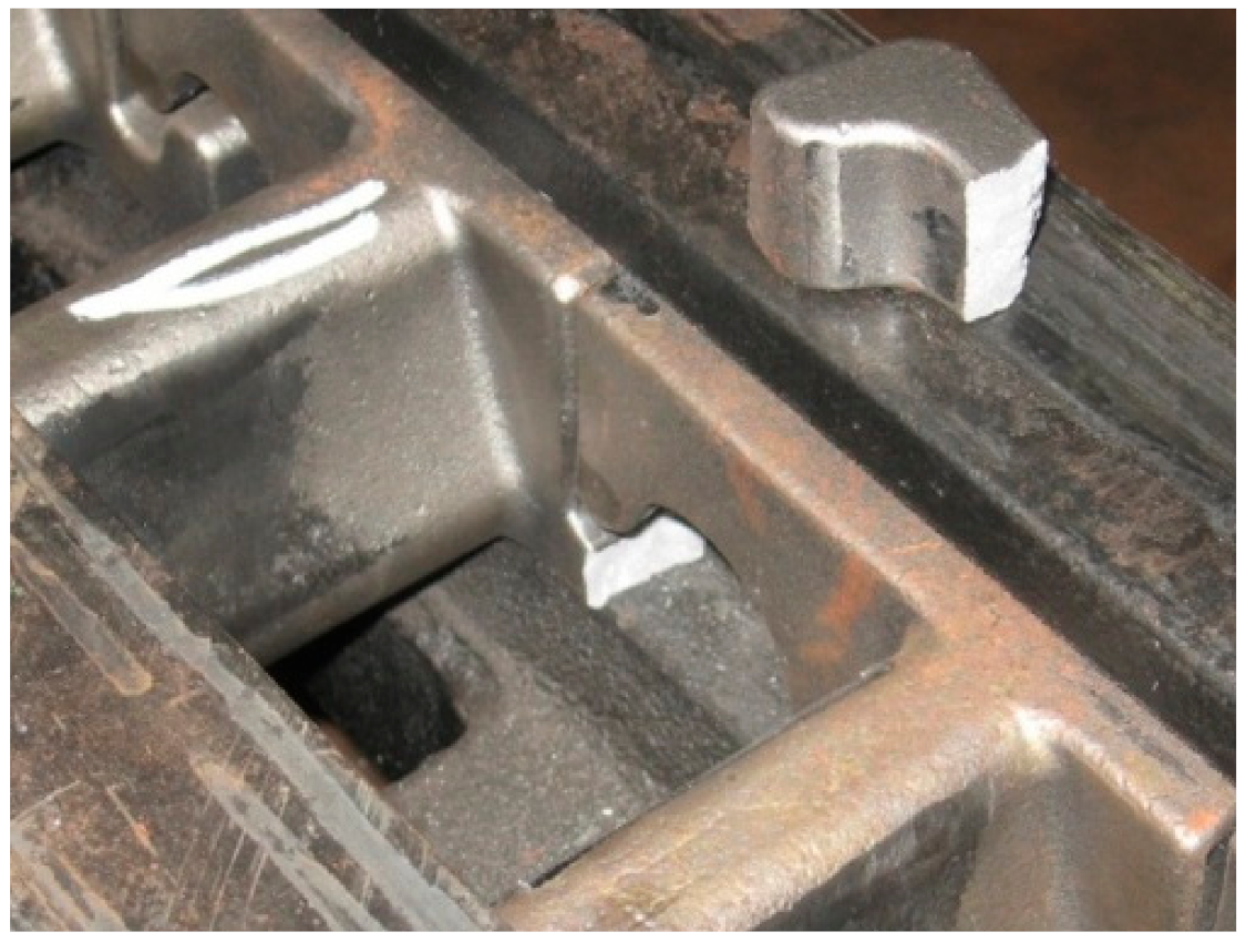
The selected design of the Type V3 toothed segments was manufactured in a prototype version, and initial functional tests of the suggested system were carried out on a test stand built on the storage yard of one of the mines belonging to PGG S.A.
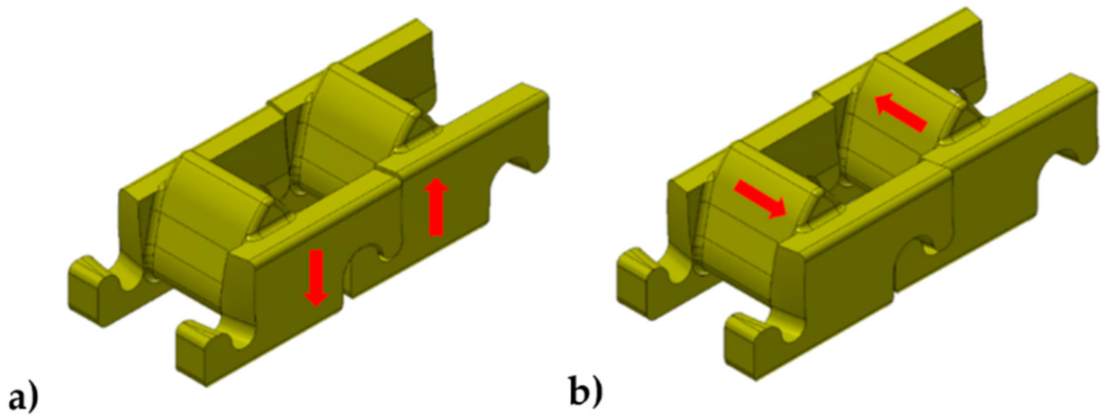
The results were satisfactory. The high flexibility of the rack during the shearer movement along the curved route of AFC was obtained. On the other hand, plastic bending of the toothed segment catches as well as their breaking at the point of the smallest cross-section surface area were reported in a few cases, as shown in Figure 21.
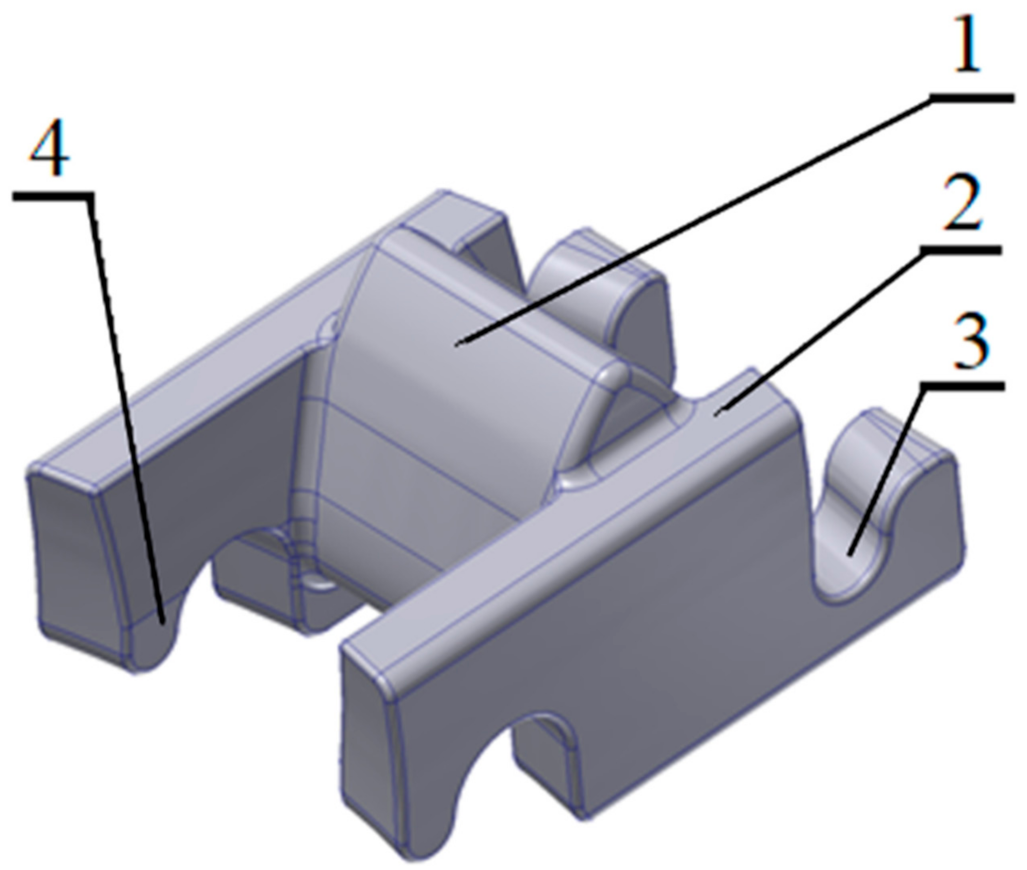
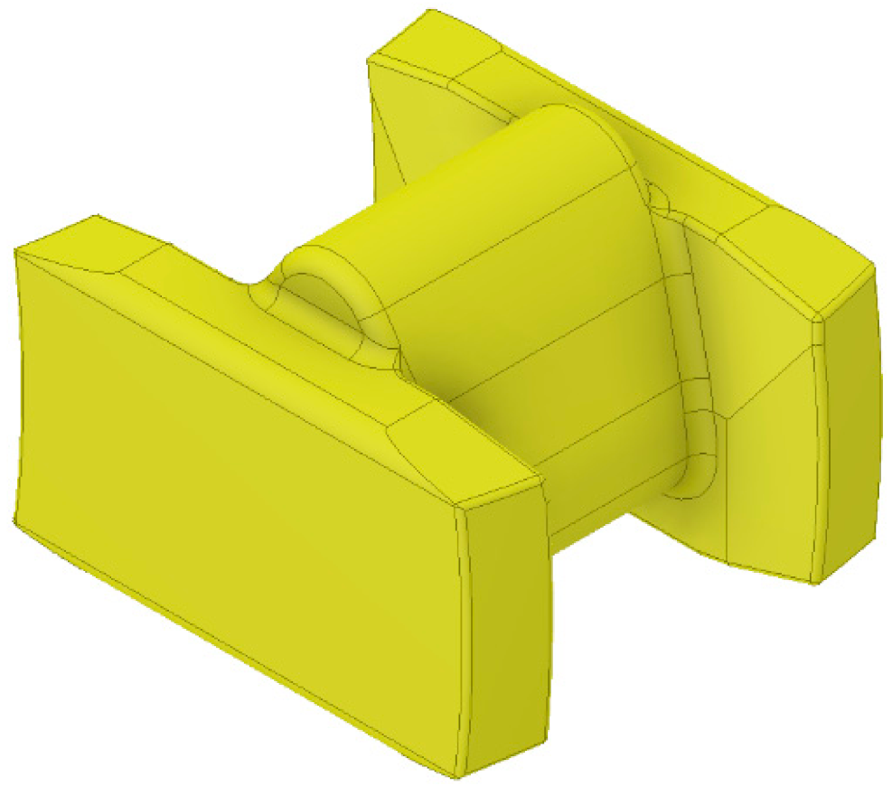
To avoid this type of damage, it was suggested to introduce changes to the design of the toothed segment. A solution of the toothed segment was developed, the 3D model of which is shown in Figure 22. The profile of the tooth flanks is the same as for the previous solution of the V3 type toothed segment, the difference is only in the height of the tooth (lower by 10 mm) and in the absence of catches. The tests concerning the slippage during the cooperation of the track wheel with the new solution of the toothed segment gave the results analogous to the results obtained for the previous version of the segment with catches. A new solution of the toothed segment without catches was used for further tests.

5. Load Analysis of the Tested Eicotrack and KOMTRACK Haulage Systems during Operation on a Bent Conveyor Section

The results of simulation tests for the Eicotrack and KOMTRACK systems in the case of the conveyor route curved in the horizontal plane are presented below. The model tests were carried out in the ANSYS LS-Dyna program, using the multibody system method. These were comparative tests, and their main purpose was to identify the loads to the track wheel, including contact forces, for the selected geometrical configurations of the haulage system. The unit was divided into subassemblies, between which appropriate kinematic pairs were defined. Subassemblies or components were the rigid bodies with appropriate mass parameters (centers of gravity, mass moments of inertia). The shearer body was loaded with a force of 562 kN, and its movement was forced by a kinematic input such as a constant angular speed of the track wheel. Standard and higher-order kinematic couplings were used to build the model. In order to model the interaction between the track wheel and the toothed segments, contact-space connections were used. Due to the time-consuming calculations, a displacement was simulated along the length of two conveyor troughs. Measurements were taken on the length of the second trough inclined by an angle of 2.5° in relation to the first one. The operation of the Eicotrack and the Ko KOMTRACK systems with Type V3 toothed segments were simulated.
Simulation tests of the displacement along the conveyor section twisted in the horizontal plane were performed first for the Eicotrack system. The displacement started with the shearer travelling along a straight section, followed by a displacement through linear racks twisted in relation to each other. The shearer’s travel was simulated until the conveyor troughs were twisted by an angle of 2.5°. During the displacement, the following assumed cooperation parameters were measured: the track wheel–linear rack, i.e., reactions in the selected kinematic nodes and contact forces. Identification of the contact force of the frame track and linear rack was the most important for analysis. A view of the model with the Eicotrack system used for the tests with the linear rack, along which the parameters were measured, is shown in Figure 23a. The resultant contact force is shown in Figure 23b. The circles mark the force peaks related to full contact of the track wheel and the rack.
The next stage of the tests was the analysis of the KOMTRACK system. The methodology of testing in this case was the same as for the Eicotrack system. A sample view of the 3D model of the shearer used during the tests is shown in Figure 24a. An upgraded toothed segment model without catches was used for testing. During the tests, the contact forces were recorded in three central toothed segments located in the guide twisted at an angle of 2.5°. The contact forces related to the selected toothed segments measured during the tests are shown in Figure 24b.
Based on the contact forces between the track wheel and the linear rack/toothed segment while passing a short test section of the conveyor route curvature in the horizontal plane, the maximum forces were recorded for the three middle teeth of the Eicotrack linear rack and the three middle, modernized toothed segments of the KOMTRACK system, which are presented as the graph in Figure 25.
On the other hand, Figure 26 shows the waveforms of the vertical contact force reaction for the Eicotrack linear track and the KOMTRACK toothed segment. The force has the greatest impact on the generation of slip of the track wheels. The results of averaged parameters for the displacement through the guide twisted at an angle of 2.5° are presented in Figure 27. It was observed that during the travel of the track wheel along the modernized KOMTRACK toothed segment, the vertical component of contact forces was lowered by more than 30%.
In the last phase of the simulation tests of the conveyor route curved in the horizontal plane (the first section of several conveyor troughs was straight, and the next sections were twisted in succession by an angle of 2.5°), comparative simulations of a track wheel travel were realized for the Eicotrack and KOMTRACK systems.
The input data for the model were determined on the basis of earlier dynamic simulations. The load as in the previous tests was assumed to be 562 kN. The simulation consisted in pressing the linear rack or toothed segment with the assumed clamping force against the tilted track wheel.
At the moment of contact of the track wheel with the Eicotrack linear rack or KOMTRACK toothed segment, the angular deviation of the track wheel plane was measured in relation to the symmetry plane of the liner rack or toothed segment. The deviations of the plane of the discretized model of the track wheel with respect to the symmetry plane of the KOMTRACK toothed segment and in relation to the symmetry plane of the Eicotrack linear rack are shown in Figure 28a and Figure 28b, respectively.
In the case of the Eicotrack linear rack, the angular deviation of the track wheel plane was measured in relation to the plane of symmetry of the linear rack, and it was 2.92°. On the other hand, the flexibility of the KOMTRACK toothed segment caused angular deviation of the track wheel plane in relation to the symmetry plane of the toothed segment to be much smaller, and it was 0.49°. Due to this method of operation, the parameters of reduced stresses generated in the toothed segments were much lower than in the case of the Eicotrack linear rack and were as follows: Type V3 KOMTRACK toothed segment = 2569 MPa; Eicotrack liner rack = 3243 MPa.

6. Conclusions

Analyses and simulations, the results of which are presented in the article, confirmed the correctness of the conclusion that the shape and geometrical dimensions of the toothed segments cooperating with the track wheel had a large impact on the unit pressures and contact forces, loads to the components of the haulage systems, as well as the sliding distance and speed. Comparing the three flank profiles of the new KOMTRACK rack solution to find the most advantageous rack profile for the new KOMTRACK haulage system in the context of the slip and contact stresses, the solution with the Type V3 involute flank appeared to be the most favorable.
The analysis of slips for the tooth profile of the V3 type rack, which was used in the KOMTRACK version, leads to the conclusion that by modifying the tooth profile, it is possible to reduce slips. It should be noted, however, that this is the result of the theoretical cooperation analysis, and the reduction of slippage results in reducing the degree of coverage for the meshing. Therefore, the risk of situations in which a very large load is transferred by a single tooth increases. When driving the shearer, it cannot be ruled out that a single tooth will carry the entire load to the shearer. Dividing the rack into segments reduces this risk by increasing its longitudinal flexibility. Therefore, the analysis of loads to the teeth was very important, taking into account various conditions related to the route configuration.
The results of comparative analysis for the components of the Eicotrack and KOMTRACK haulage system allowed for the conclusion that the use of the modernized design of the KOMTRACK Type V3 toothed segment (without catches) significantly reduced the stress and load in relation to the Eicotrack linear rack.
The dynamic tests, in the conditions of traveling along the bended section of the conveyor, gave very good results. During the simulation tests, no collision of the track wheel teeth with the guides and side surfaces of the toothed segments was observed. The toothed segments change their angular position in the guide and thus the angle between the plane of the wheel and the plane of symmetry of the rack is reduced. The measured angle of deviation of the track wheel plane with respect to the symmetry plane of the Eicotrack ladder was 2.92°, and in the case of the KOMTRACK rack, the angle of deviation of the plane of the track wheel in relation to the symmetry plane of the rack was lower and amounted to 0.49°. This proves that the KOMTRACK rack is flexible.
Cooperation between the components of the standard Eicotrack haulage system and the new Komtrack haulage system with the Type V3 rack (without catches) was verified in kinematic and dynamic computer tests, simulated for the AFC route bent in the horizontal plane (angle of twist of each conveyor trough in relation to the previous one by minimum 2.5°, which in mining conditions enables obtaining the web depth of about 0.8 m), i.e., in extreme operational conditions.
When the components of the haulage system were loaded during the travel of the track wheel, the maximum resultant contact force for the KOMTRACK rack was lower by at least 20% (Eicotrack = 311 kN, KOMTRACK = 248 kN).
Taking into account the vertical contact force reaction, which is responsible for the slippage of the track wheel when moving along the rack or linear rack along the conveyor route, the Komtrack system obtained over 33% lower average values of this reaction compared to the Eicotrack system (Eicotrack = 168 kN, KOMTRACK = 111 kN).
Comparing the reduced stresses generated in the components of the haulage systems during travel of the track wheel along the conveyor route with the troughs twisted in relation to each other by an angle of 2.5°, it was found that the stresses in the KOMTRACK system were about 25% lower than in the Eicotrack system; KOMTRACK rack = 2569 MPa; Eicotrack linear rack = 3243 MPa.
Taking into account the positive results of the simulation tests with the modernized version of the KOMTRACK rack, it can be assumed with high probability that the use of the new version of the KOMTRACK Type V3 rack (without catches) in underground conditions will bring the expected effect: lowering the load to the cooperating components reducing their wear rate, especially the wear of the track wheels. This is confirmed by the preliminary results of the bench tests performed at PGG S.A.

Author Contributions

Conceptualization, writing—original draft preparation, writing—review and editing, supervision, M.K. and K.K.; methodology, software, validation, formal analysis, visualization, K.K., G.S., and M.K.; investigation, data curation, resources, M.S. and D.B.; project administration and funding acquisition, M.K., M.S. and D.B. All authors have read and agreed to the published version of the manuscript.

Funding

The article was based on the results of the tests carried out within the research project entitled “New generation high-performance haulage system of the longwall system” co-financed by the European Regional Development Fund (Contract no. POIR.04.01.04-00-0068/17).

Institutional Review Board Statement

Not applicable.

Informed Consent Statement

Not applicable.

Data Availability Statement

Not applicable.

Conflicts of Interest

The authors declare no conflict of interest.

References

  1. Sikora, W.; Dolipski, M.; Osadnik, J.; Remiorz, E. Analiza geometryczna wybranych elementów układu ciągnienia 2BP. In Proceedings of the Górnictwo Zrównoważonego Rozwoju 2005 Konferencja Naukowa, Zeszyty Naukowe Politechniki Śląskiej, Górnictwo, Gliwice, Poland, 24 November 2005; pp. 543–551. (In Polish). [Google Scholar]
  2. Korski, J. Capacity Losses Factors of Fully Mechanized Longwall Complexes. Min. Mach. 2020, 6, 12–21. [Google Scholar]
  3. Biały, W.; Czerwiński, S. Analiza pracy maszyny urabiającej w wyrobisku ścianowym. Mech. Autom. Górnictwa 2011, 4, 5–14. (In Polish) [Google Scholar]
  4. Sikora, W. Obciążenia Dynamiczne w Układach Ciągnienia Wysoko Wydajnych Kombajnów Ścianowych; Wydawnictwo Politechniki Śląskiej: Gliwice, Poland, 2005. (In Polish) [Google Scholar]
  5. Fries, J. Rozwój bezcięgnowych systemów posuwu kombajnów ścianowych. Uhli Rudy Geol. Pruzk. 2003, 5, 22–24. [Google Scholar]
  6. Gondek, H.; Marasova, D.; Fries, J. Możliwości zwiększenia trwałości zazębienia koła napędowego z zębatką mechanizmu bezcięgnowego posuwu kombajnu ścianowego. In Proceedings of the TEMAG 2000 Trwałość Elementów i Węzłów Konstrukcyjnych Maszyn Górniczych, VIII Konferencja Naukowo-Techniczna, Gliwice, Ustroń, Poland, 25–27 October 2000; pp. 73–80. (In Polish). [Google Scholar]
  7. Giza, T.; Sobota, P.; Osadnik, J. Analiza stosowanych mechanizmów ciągnienia ścianowych kombajnów węglowych. In Proceedings of the KOMTECH 2002, III Międzynarodowa Konferencja Naukowo-Techniczna Kierunki Mechanizacji Górnictwa do 2010 Roku, t. I, Szczyrk, Poland, 5–7 November 2002; pp. 151–161. (In Polish). [Google Scholar]
  8. Kalita, M.; Mazurkiewicz, A.; Pieczora, E.; Tarkowski, A. KOMTRACK—Nowej Generacji System Posuwu Wysokowydajnych Kompleksów Ścianowych—Wstępne Prace Projektowe Mechanizacja, Automatyzacja I Robotyzacja W Górnictwie; Wydawnictwa AGH: Kraków, Poland, 2020; pp. 23–31. (In Polish) [Google Scholar]
  9. Kalita, M. Designing process of a toothed segment of the KOMTRACK haulage system. New Trends Prod. Eng. 2019, 2, 121–129. [Google Scholar] [CrossRef] [Green Version]
  10. Fries, J. Współpraca bezcięgnowych systemów posuwu o różnych profilach. In Proceedings of the Górnictwo Zrównoważonego Rozwoju 2002; Zeszyty Naukowe Politechniki Śląskiej, Górnictwo: Gliwice, Poland, October 2002; pp. 121–132. [Google Scholar]
  11. Sobota, P.; Giza, T.; Cheluszka, P.; Osadnik, J. Analiza warunków eksploatacji mechanizmów ciągnienia ścianowych kombajnów węglowych. In Proceedings of the Górnictwo Zrównoważonego Rozwoju 2002; Zeszyty Naukowe Politechniki Śląskiej, Górnictwo: Gliwice, Poland, October 2002; pp. 247–255. (In Polish) [Google Scholar]
  12. Peng, S.S.; Du, F.; Cheng, J.Y.; Li, Y. Automation in U.S. longwall coal mining: A state-of-the-art review. Int. J. Min. Sci. Technol. 2019, 29, 151–159. [Google Scholar] [CrossRef]
  13. Matsui, K.; Shimada, H. Control of stability of retreat longwall gate road. Min. Sci. Technol. 1996, 7, 709–713. [Google Scholar]
  14. Boloz, L.; Bialy, W. Automation and Robotization of Underground Mining in Poland. Appl. Sci. 2020, 10, 7221. [Google Scholar] [CrossRef]
  15. Si, L.; Wang, Z.B.; Tan, C.; Liu, X.H.; Xu, X.H. A feature extraction method for shearer cutting pattern recognition based on improved local mean decomposition and multi-scale fuzzy entropy. Curr. Sci. 2017, 112, 2243–2252. [Google Scholar] [CrossRef]
  16. Linnik, Y.N.; Linnik, V.Y.; Zhabin, A.B.; Polyakov, A.V. Theoretical framework for the efficiency evaluation of coal mining machines. Eurasian Min. 2020, 1, 61–64. [Google Scholar] [CrossRef]
  17. Sikora, W.; Giza, T.; Mann, R. Wpływ przegięcia trasy przenośnika zgrzebłowego na współpracę koła napędowego z zębatką bezcięgnowego systemu posuwu typu BP. In Proceedings of the TUR 2003, III Międzynarodowa Konferencja Techniki Urabiania 2003, Kraków, Krynica, Poland, 17–20 September 2003; pp. 151–159. (In Polish). [Google Scholar]
  18. Giza, T.; Mann, R. Wpływ zużycia zębów koła napędowego i zmiany podziałki zębatki na charakter zazębienia i prędkość posuwu kombajnu. In Proceedings of the Górnictwo Zrównoważonego Rozwoju 2005, Konferencja Naukowa, Gliwice, Poland, Listopad 2005; Zeszyty Naukowe Politechniki Śląskiej, Górnictwo: Gliwice, Poland, 2005; pp. 407–416. (In Polish) [Google Scholar]
  19. Giza, T.; Sobota, P.; Mann, R. Wpływ zazębienia koła napędowego z zębatką sworzniową mechanizmu posuwu BP na parametry posuwu kombajnu ścianowego. In Proceedings of the KOMTECH Nowoczesne, Niezawodne i Bezpieczne Systemy Mechaniczne w Świetle Wymagań Unii Europejskiej, Szczyrk, Poland, 17–19 November 2003; pp. 189–197. (In Polish). [Google Scholar]
  20. Kotwica, K.; Stopka, G.; Gospodarczyk, P. Simulation tests of new solution of the longwall shearer haulage system. In Proceedings of the Scientific and Technical Conference on Innovative Mining Technologies (IMTech), Szczyrk, Poland, 14–16 October 2019; pp. 67–76. [Google Scholar]
  21. Morshedlou, A.; Dehghani, H.; Hoseinie, S.H. A data driven decision making approach for long-wall mining production enhancement. Min. Sci. 2019, 26, 7–20. [Google Scholar] [CrossRef]
  22. Ochęduszko, K. Koła Zębate T. 1 Konstrukcja; WNT: Warsaw, Poland, 1985. (In Polish) [Google Scholar]
Figure 1. Model of a shearer haulage system of Eicotrack type.
Energies 14 02720 g001
Figure 2. Damaged track wheels of the Eicotrack system.
Energies 14 02720 g002
Figure 3. Flextrack haulage system: (a) 3D model, (b) tooth flank outline of the rack segment.
Energies 14 02720 g003
Figure 4. Damages to the track wheel and the Flextrack racks during the field tests.
Energies 14 02720 g004
Figure 5. 3D model of a rack segment: 1—tooth, 2—side wall, 3—socket, 4—catch.
Energies 14 02720 g005
Figure 6. Possible movement of the rack segments-direction: (a) vertical, (b) horizontal.
Energies 14 02720 g006
Figure 7. 3D model of KOMTRACK system components.
Energies 14 02720 g007
Figure 8. Diagram showing the slip formation: (a) diagram of the slip speed for different points of teeth profile, (b) sense of a vector of slip speed on teeth side surfaces [22].
Energies 14 02720 g008
Figure 9. Selected geometric profiles of teeth: (a) Type V1, (b) Type V2, (c) Type V3.
Energies 14 02720 g009
Figure 10. Diagrams of angular speed of the track wheel ω (blue color), displacement L of the model of the wheel drive (pink color), and the linear speed of this displacement Vs (red color) for Komtrack toothed segments—(a) Type V1, (b) Type V2, and (c) Type V3.
Energies 14 02720 g010
Figure 11. Situation before the track wheel enters the buttress with a rack.
Energies 14 02720 g011
Figure 12. Toothed segment Type V1: (a) moment of starting the slip—slip speed about 16.1 mm/s, (b) slip of the track wheel surface when entering the buttress with a rack, slip speed at the moment of contact about 17.57 mm/s.
Energies 14 02720 g012
Figure 13. Toothed segment Type V2: (a) moment of starting the slip—slip speed about 15.1 mm/s, (b) slip of the track wheel surface when entering from top the buttress with a rack, slip speed at the moment of contact about 21.3 mm/s.
Energies 14 02720 g013
Figure 14. Toothed segment Type V3: (a) slip of the track wheel surface when entering the buttress with a rack for a point significantly far from the cut, slip speed at the moment of contact, about 11.6 mm/s, (b) contact point moves along the rack surface, slip speed reduces to about 9.0 mm/s.
Energies 14 02720 g014
Figure 15. Eicotrack linear rack: (a) moment of starting the slip when entering the buttress with a rack, slip speed about 14.2 mm/s, (b) slip of the track wheel tooth tip, slip speed at the moment of contact about 15.7 mm/s.
Energies 14 02720 g015
Figure 16. The general isometric view (a) and the cross-section of the assembly of the track wheel with toothed segments (b) assumed for the purpose of the analysis of slips in the kinematic pair of the KOMTRACK feed system.
Energies 14 02720 g016
Figure 17. View of the analyzed positions of the track wheel with the toothed segments.
Energies 14 02720 g017
Figure 18. Toothed segment flank slippage in relation to the track wheel.
Energies 14 02720 g018
Figure 19. Diagram of the kinematic pair—track wheel-Type V3 toothed segment slippage in a function of the track wheel rotation angle.
Energies 14 02720 g019
Figure 20. Diagram of changes in the following forces: pulling force, inter-teeth force, and vertical component Y in a function of track wheel rotation angle.
Energies 14 02720 g020
Figure 21. View of one of the damaged toothed segments of the Komtrack system.
Energies 14 02720 g021
Figure 22. 3D model of the modernized toothed segment Type V3.
Energies 14 02720 g022
Figure 23. Model tests of the identification of the loads to the track wheel during the displacement of the linear track inclined by 2.5°: (a) model for the Eicotrack system, (b) the resultant contact force.
Energies 14 02720 g023
Figure 24. 3D model of the modernized toothed segment Type V3. Model tests for the identification of the loads on the track wheel while moving over the rack inclined by the angle of 2.5°: (a) model of the KOMTRACK system, (b) the resultant contact forces: toothed segment 1—grey color, toothed segment 2—green color, toothed segment 3—blue color.
Energies 14 02720 g024
Figure 25. Diagram of the maximum contact forces (for the three middle components of linear racks/toothed segments) for the Eicotrack and KOMTRACK systems.
Energies 14 02720 g025
Figure 26. The parameters of the vertical component of contact forces at the point of contact: (a) track wheels—Eicotrack system linear rack, (b) track wheels—modernized KOMTRACK system: toothed segment 1—red color, toothed segment 2—blue color.
Energies 14 02720 g026
Figure 27. Average parameters of the vertical component of contact forces for the displacement through a guide twisted at an angle of 2.5°.
Energies 14 02720 g027
Figure 28. View of the deviation of the track wheel plane in relation to the symmetry plane: (a) KOMTRACK toothed segment, (b) Eicotrack linear rack.
Energies 14 02720 g028
Publisher’s Note: MDPI stays neutral with regard to jurisdictional claims in published maps and institutional affiliations.

