1. Introduction
Transport is one of the most important processes in modern coal mining. Despite the introduction of modern and safer transportation systems, accident statistics show that this area still requires considerable improvement. During transportation carried out in underground workings, there are a number of processes and events, during which natural and technical hazards to workers’ health or even life (fatal accidents) can occur. The mine auxiliary horizontal transportation system is one of the most dangerous processes [
1].
Transportation of materials in underground mine workings is realized by mine underground railways (on the main transportation routes) as well as by suspended monorails or floor-mounted railways (in a department transportation). Transportation is realized on tracks placed on the floor of working (floor-mounted rail transportation realized on transportation platforms) or on rails suspended to roadway support (suspended rail transportation realized by modular load-carrying units) [
1].
The problem of possible collision between transported object and equipment of the transport roads is well known for many years. Identification of possible collisions is crucial at the transportation routes design and also during the exploitation, due to possible changes of the mining working environment. Inadequate consideration of this factor may cause serious damages to transportation routes and equipment. In a typical way, the collision was analyzed on-site, by manual measurement in several points of transportation routes, or by using a physical mockup of transported elements. These methods are inaccurate and due to fact that it is not possible to simulate the kinematics of the whole transportation systems by using simple mockups or measuring tape, a new approach was needed.
The bigger dimensions of the transported equipment and materials are, the more probable collision between transported loads and roadway support components, the equipment or other machines. Hazard to the personnel present on the transportation routes is also higher. This forces designers to analyze the transportation routes in terms of possibility of the collisions mentioned above [
2]. During design and construction of new means of transport specialized software tools in the process of virtual prototyping are used [
3].
This especially concerns transportation of big-size and long loads [
4]. During transportation by suspended monorail, longitudinal and transverse traverses that protrude out of the load outline are also classified as the long material.
During the assembly and liquidation of longwalls, transportation of large-size loads accounts for a significant percentage of all transportation tasks carried out. These are sections of powered roof support, parts of armored face conveyors (AFC) and components of a longwall shearer.
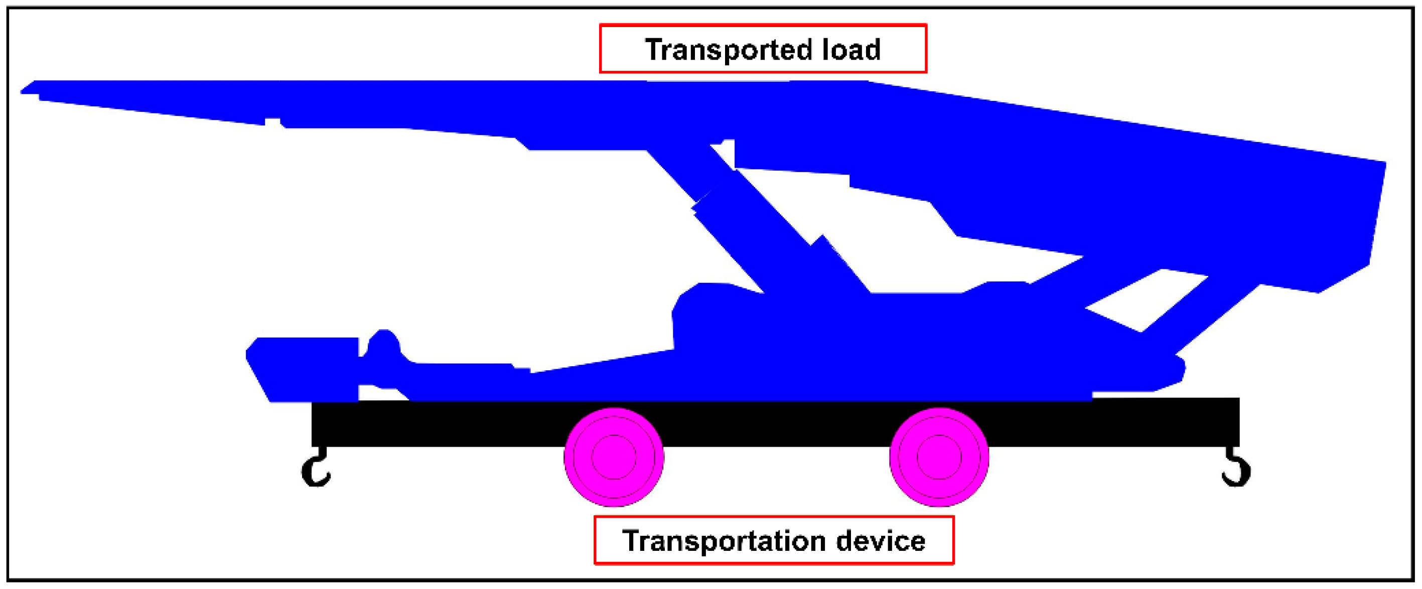
Figure 1 shows the transportation of powered roof support (big-size load) on a transportation platform (floor mounted rail transportation).
In addition to analysis of existing routes to identify possible collisions, also meeting requirements regarding traffic clearances between elements of the transportation devices, the side wall and the floor has to be verified.
Collision free transportation is conditioned by proper designing of the underground working, proper designing of the track and proper selection of the transportation system. Collision analysis regarding transportation routes is especially important in the case of designs of transportation system in which there is reduction of area of roadway cross-section in a result of impact of the surrounding rock mass. A special software to aid collision analyzes in auxiliary underground transport has been developed by KOMAG Institute of Mining Technology and implemented at Jastrzębska Coal Company [
5].
Analyzes to identify possible collisions during transportation can be carried out based on the real and current dimensions of the underground working, obtained in the process of 3D scanning, which is a subject of the current research in KOMAG. Creation of 3D model of underground working is also possible with the aid of photographic camera and mobile computer [
6]. These analyzes are carried out using 3D geometrical models of the underground working (developed with use of 3D scanning) and 3D geometrical models reflecting the solid trace of the transported load (developed with use of computer simulations within CAD/MBS software).
3D laser scanning is a non-contact, non-destructive technology that digitally captures the shape of physical objects using a line of laser light. ‘Point cloud’ that is a set of data points in space, replicating the scanned object, is created. Each point has its set of X, Y and Z coordinates. Point clouds can be used to create 3D models of the scanned objects, for reverse engineering, virtual prototyping and for quality control [
7]. Depending on the object, 3D model obtained based on data obtained via 3D scanning can be also used for 3D printing of this object [
8].
Nowadays, 3D laser scanning has become a method used in product development and in creating of computer animations. Laser scanners are used in the measurement and design of industrial objects: machinery, systems, installations and places, the degree of complexity of which is so high that traditional methods do not produce the desired effect.
Currently, the use of the 3D laser scanning becomes more and more common, covering a variety of applications. In road transport, this technique is used e.g., in the sight distance assessment method. Keeping sufficient sight distance throughout a road’s service life is crucial to enable drivers to safely carry out certain manoeuvres such as stopping or passing and 3D scanning can be used to collect necessary data [
9]. In the case of drones, this technique can also be used for large-scale measurement purposes, e.g., to establish the location of cranes while lifting large-size technical objects in a petrochemical plant [
10]. It can also be combined with other modern technologies, such as 3D printing. This compilation was used in [
11] for reproduction of historical building ornamental components. Application of 3D scanning to improve safety of machine’s operator was presented in [
12]—3D environment map developed with use of 3D scanning system is a component of multisensor-driven real-time crane monitoring system for crane operators.
The 3D scanning method is often used for the digitalization of large spaces for further processing it using specialized software. Besides the standard implementation of 3D scanning technology on the surface, this method may be applied also for tunnel [
13] and underground mining [
14,
15] surveying. The result of the 3D scanning process may be utilized for collision analysis [
16] and also as a basis for other activities e.g., for post-accident analysis [
17] where the process of fast evidence collecting and freezing the scene is crucial. Presented examples solve a specific problem that occurs during underground transportations system operation, but also in other sectors this problem was analyzed [
18]. The prediction and analysis of the trajectory of transportation system components are crucial for narrow passages and tunnels. And this is the main issue that has to be identified and predicted at each stage of design and carrying out of the transportation processes.
In computer aided design, additional, useful opportunities are provided by Virtual Reality (VR) that enables to see and analyze ‘3D virtual representation’ of the designed object, in the three-dimensional virtual world one immerses in. Interaction with the ‘virtual object’ helps e.g., to detect errors in the design, compare different design variants etc. Application of VR in design of transportation system and transportation process is discussed in this article.
2. Proposed Method
The proposed method supports the designer of mining transportation routes in which auxiliary transport is carried out by floor-mounted railways or suspended monorails. The method involves the use of the following computer techniques:
3D Laser Scanning—obtaining the current shapes and geometrical dimensions of the underground working in which transportation is carried out;
Computer Simulations—creating a “3D trace” of the load transported by the selected transportation device;
Virtual Reality—visualization of the obtained results.
The following tools are to be used:
3D laser scanner—3D scanning of the selected area of underground working;
Program for processing the point cloud—selecting the axis of the route, integrating the 3D model of the underground working with the 3D trace of the transported load, obtaining longitudinal and transverse sections, identifying areas of potential collision;
Text editor—formulation of the transportation task, creating a collision analysis report;
CAD/MBS program—obtaining a 3D trace of the transported load;
CAD program—description of the obtained transverse and longitudinal sections, designing/redesigning process of the selected area of underground workings;
VR hardware and software—visualization of the obtained results.
The method consists of five stages:
STAGE 1—3D scanning of the selected area of underground working;
STAGE 2—3D simulations of transportation process;
STAGE 3—identification of areas of potential collision;
STAGE 4—redesign of supports in the mine underground working;
STAGE 5—visualization of the results using Virtual Reality.
A 3D model of the mine underground working and a 3D model reflecting the trace of the transported load are integrated in a computer software tool (point cloud processing software) to obtain one 3D model, including both the mine underground working and the trace of the transported load.
Next, the 3D model is analyzed to identify the areas of possible collision. These areas are next cut with planes to obtain cross-sections of the transported load and underground workings along with supports—for more detailed measurement.
During the STAGE 1, the following STEPS are performed:
STEP 1 (3D scanner)—performing a 3D scan of the selected area of the underground working, including transportation routes for floor-mounted railways and suspended monorails;
STEP 2 (point cloud processing software)—importing of the 3D scanner output file; point cloud simplification; selection of route’s fragment for analysis; extracting the route’s fragment and exporting it to a text or DXF file;
STEP 3 (text editor, website form)—specification of the transportation task: the analyzed area of the underground working, drawing units, direction of transport; type of transport: floor-mounted railways/suspended monorails; transported load; transportation device: transportation platform (floor-mounted railways)/modular load-carrying unit (suspended monorails); the orientation of the transported load in relation to the transportation device; CAD/MBS simulation parameters.
During the STAGE 2, the following STEPS are performed:
During the STAGE 3, the following STEPS are performed:
STEP 5 (point cloud processing software)—loading the file that contains scan of the underground working with the selected route’s fragment; importing of the OBJ file containing 3D traces of the transported load; orientation of the load’s traces in relation to the route; converting the load’s traces into a point cloud; determination of cross-sections of the underground working (including both the support and the transported load) and their export to a DXF file; identifying areas of potential collision;
STEP 6 (CAD program)—importing a DXF file containing selected cross sections—description of sections;
STEP 7 (text editor)—filling in a report template (file)—creating a 3D collision analysis report.
During the STAGE 4, the following STEPS are performed:
During the STAGE 5, the following STEPS are performed:
Each stage and step of the method are described below.
2.1. 3D Laser Scanning (STAGE 1)
Acquiring the actual shape and geometrical dimensions of the selected area of the underground working, along with the existing infrastructure (pipelines, belt and scraper conveyors, road machines, etc.) and route of transportation, is a primary purpose of scanning the selected area of the underground working. Data collected can be then used for selection of machinery and planning of transportation processes for the underground working.
The selected area for scanning should be a part of the underground working, including transportation routes for floor-mounted railways and/or suspended monorails, on which collisions may occur during transportation, containing:
Length of the selected fragment of underground working should meet the following requirements:
Minimum length—should enable placing on the route a transportation device along with the load (about 4 ÷ 5 m for floor-mounted railways, about 10 ÷ 15 m for suspended monorails);
Maximum length—as determined; longer fragments should be broken down into smaller ones.
Simplification of the point cloud, obtained from 3D scanner, requires: reducing the point cloud density (the number of points per given volume), grouping the point cloud, creating cross-sections, and identifying the transportation route.
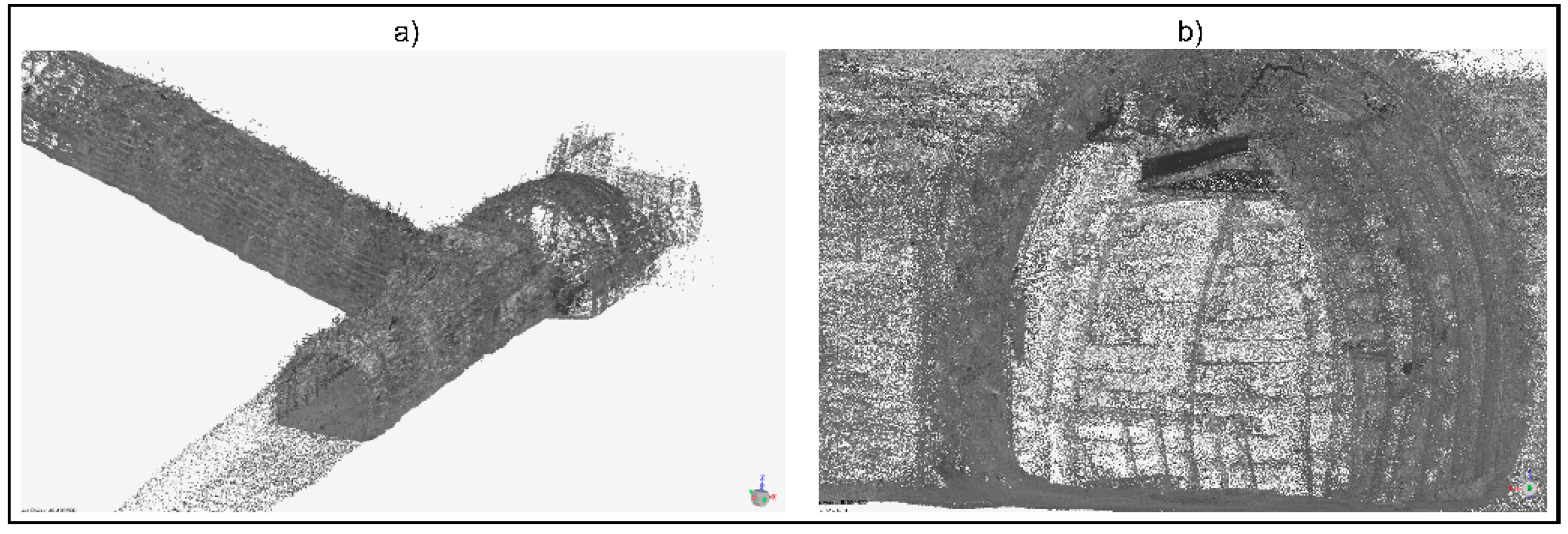
The results from STAGE 1 are: point cloud (input for STAGE 3) and a determined transportation route, saved in a text file or CAD DXF file (input for STAGE 2). Example of output from STAGE 1 is presented in
Figure 2, showing the scan of a selected part of the underground working, located in the Historic Coal Mine GUIDO in Zabrze (Poland). The subject of the scan was a part of the underground working (crossroad) intended for the transportation of materials and people. The following material objects were scanned: (a) crossroad with arch yielding supports, (b) suspended monorail route with pipelines and a suspended monorail.
2.2. Computer Simulations (STAGE 2)
A basic task in collision detection is to produce a continuous object’s motion from its start point to its end point, avoiding collision with known obstacles. The motion of an object and the obstacles’ geometry is described in a 3D workspace, while the motion path is represented as a continuous line, within 2D or 3D workspace.
Determination of the 3D trace of the load transported with the selected transportation device (transportation platform for floor-mounted railways, modular load-carrying unit with traverses for suspended monorails) is the primary purpose of computer simulations. The 3D trace of the transported load can be obtained as a result of computer simulation carried out in a CAD (Computer Aided Design) or MBS (Multibody System) software.
The advantage of CAD/MBS software is their open architecture, allowing for the extension of their functionality by creating specific software tools (external computer applications) that run in the CAD/MBS software, using their database of graphic components, automating repetitive tasks or performing additional engineering calculations. In the case of AutoCAD, VisualLISP is one of the programming languages.
To determine the 3D traces of the transported load, the transportation platform (floor-mounted railway) or transverse and longitudinal traverses (suspended monorail), it is necessary to place a transportation device with the load on the route. This takes place differently, depending on the transportation device used.
For floor-mounted railway transportation:
The transported load does not change its position in relation to the transportation device;
When passing a bend, transported load approaches the outside of the bend;
The simulation of passing the transportation device with the load on a selected part of the route consists in determining their location at given route points.
For suspended monorail transportation:
The transported load changes its position in relation to the transportation device, which is caused by the design of the modular load-carrying unit, and the way the load is attached to it;
When passing a bend, transported load approaches the inside of the bend;
In order to simulate the passing transportation device with traverses and the load on a selected segment of the route, first the kinematic chain of the transportation device should be determined at a given point of the route. Then the orientation of the transported load in relation to the transportation device should be done.
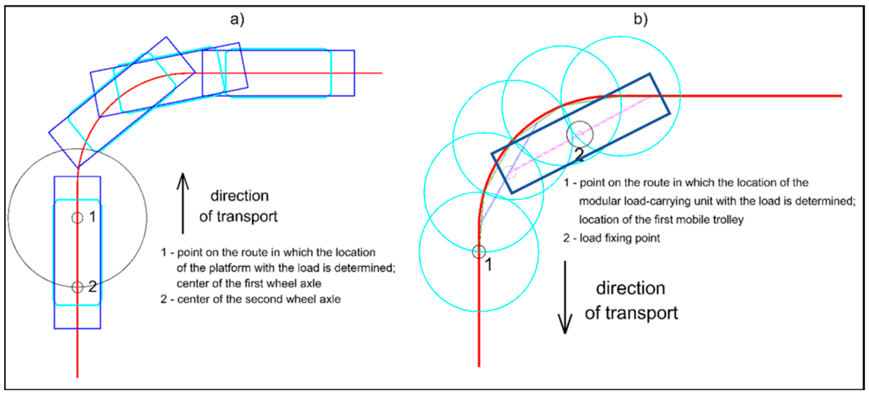
An example of determining the location of a transportation device with a load at a given point of a route, for floor-mounted railway (using the transportation platforms) and for suspended monorail (using the modular load-carrying units), is presented in
Figure 3.
During the simulation, the transportation device with the load moves along the route (from the starting point to the end point) within the given simulation step. In each simulation step, the location of the transportation device with the load is determined. After each simulation step, a trace of the transported load is marked (with no traffic clearances and with given traffic clearances). After completing the simulation, 3D traces of the load along the route are obtained. The exemplary output from STAGE 2 (transportation of powered roof support using a transportation platform) is presented in
Figure 4.
The results of the computer simulation of transportation process (output from STAGE 2) are to be used as input data for the collision analysis of the transportation device and the transported load with the arch yielding support and equipment of the underground working in which the transportation is carried out (STAGE 3).
2.3. Identication of Areas of Potential Collision (STAGE 3)
During the STAGE 1, a 3D scan of the selected area of the underground working, containing the transportation routes, was made. In STAGE 2, computer simulations were performed in order to obtain the 3D trace of load transported along a selected part of the route, using a selected transportation device (transportation platform for floor-mounted railways, modular load-carrying unit with traverses for suspended monorails). In STAGE 3, results obtained from STAGE 1 and STAGE 2, are integrated in a computer software tool (CloudCompare processing software). The purpose is to obtain one 3D model, including both the mine underground working and the trace of the transported load. With obtained 3D model, a collision analysis of the transportation device and the transported load with the arch yielding support and equipment of the underground working in which the transportation was carried out, can be done. Identifying areas of potential collision is the main purpose of STAGE 3, in the proposed method.
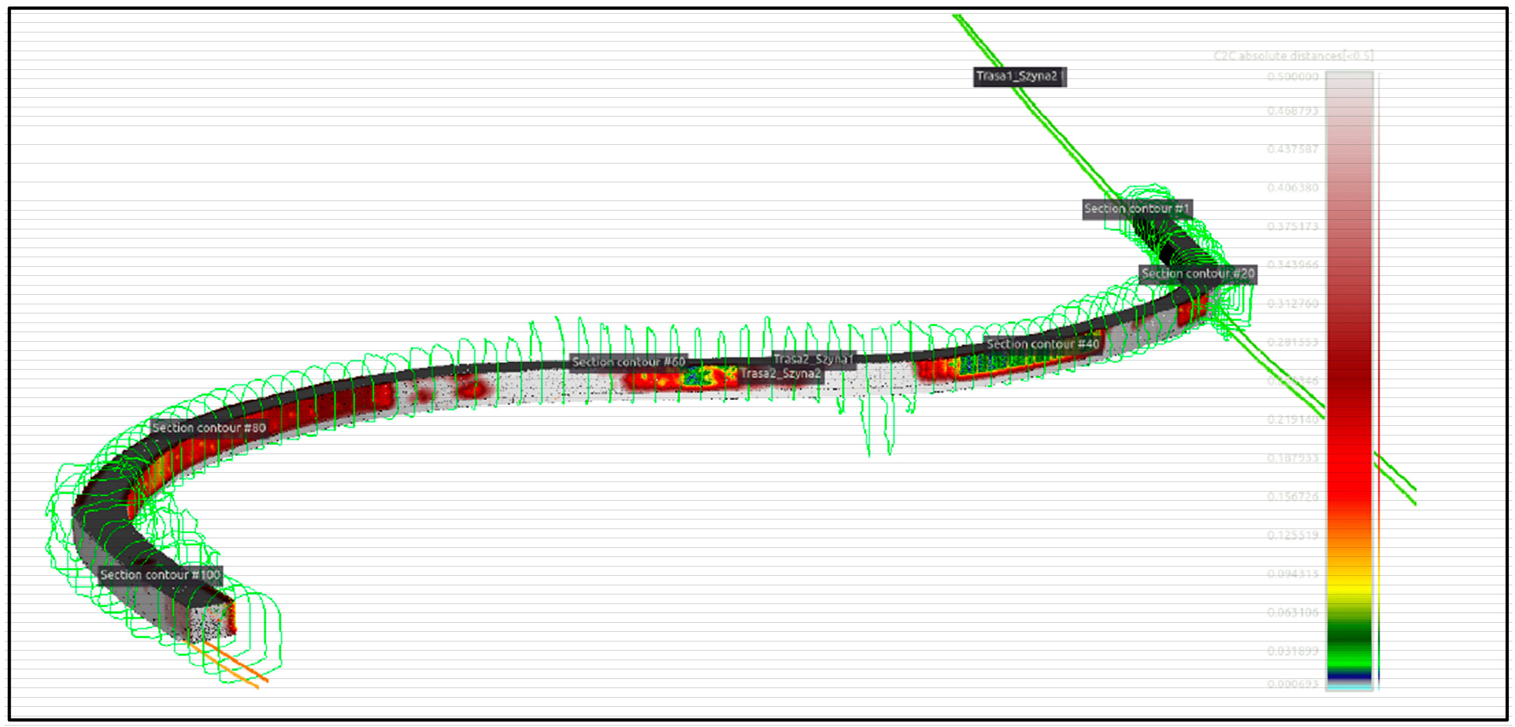
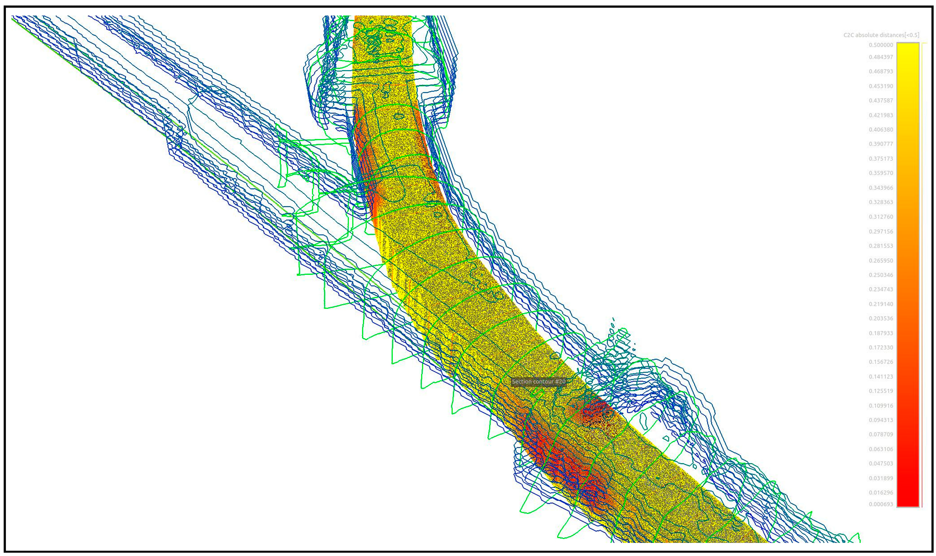
For the purposes of the collision analysis, the 3D trace of the transported load was converted into a point cloud. Then, having two clouds of points: the underground working with its equipment (reference cloud) and trace of transported load (compared cloud), it is necessary to select the tool ‘Cloud-to-Cloud Distance computation => nearest neighbor distance’ in CloudCompare software. For each point in the compared cloud, CloudCompare searches the nearest point in the reference cloud and computes their distance. The result is shown as colored map of distances, where every point from the compared cloud is colored according to its distance to reference cloud. The example is shown in
Figure 5.
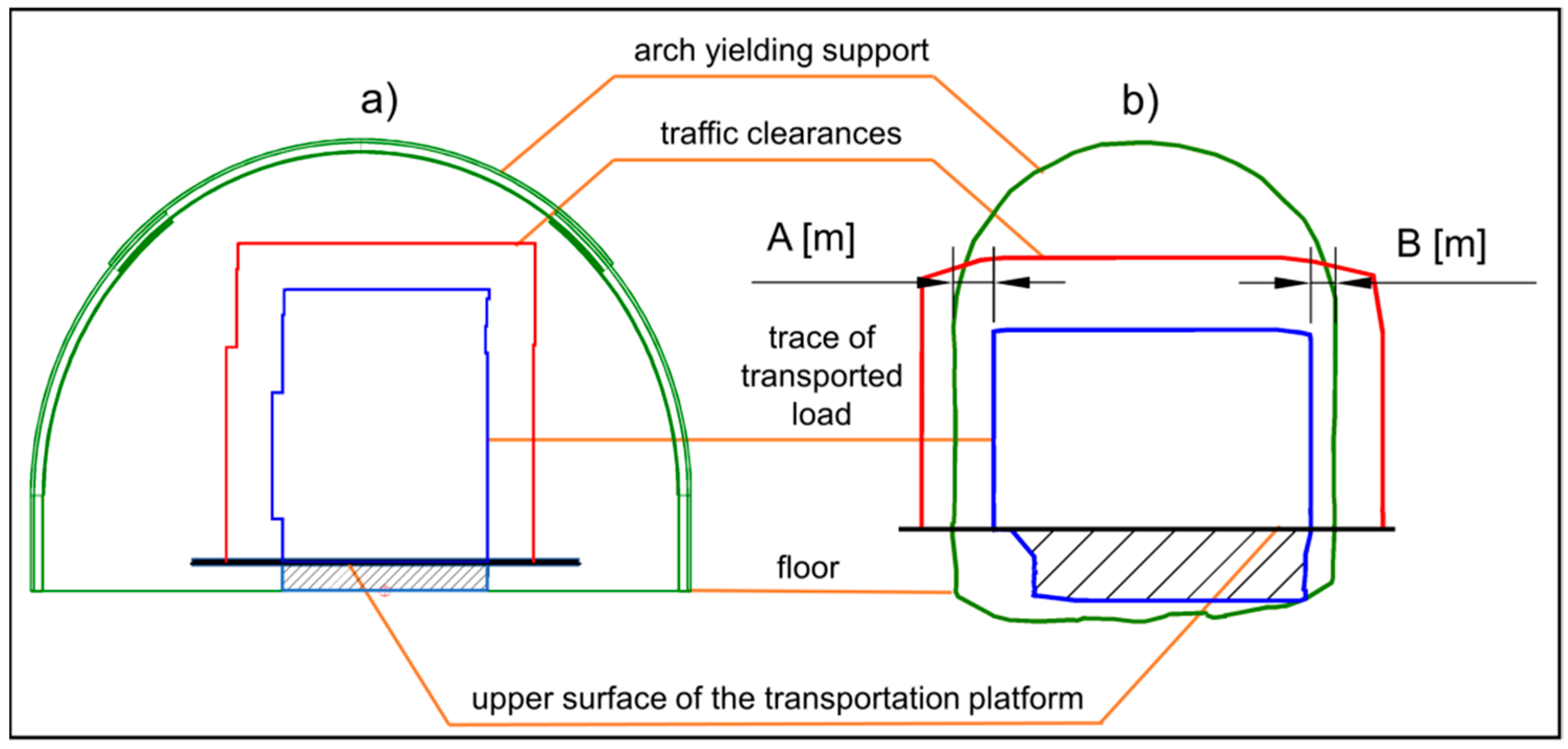
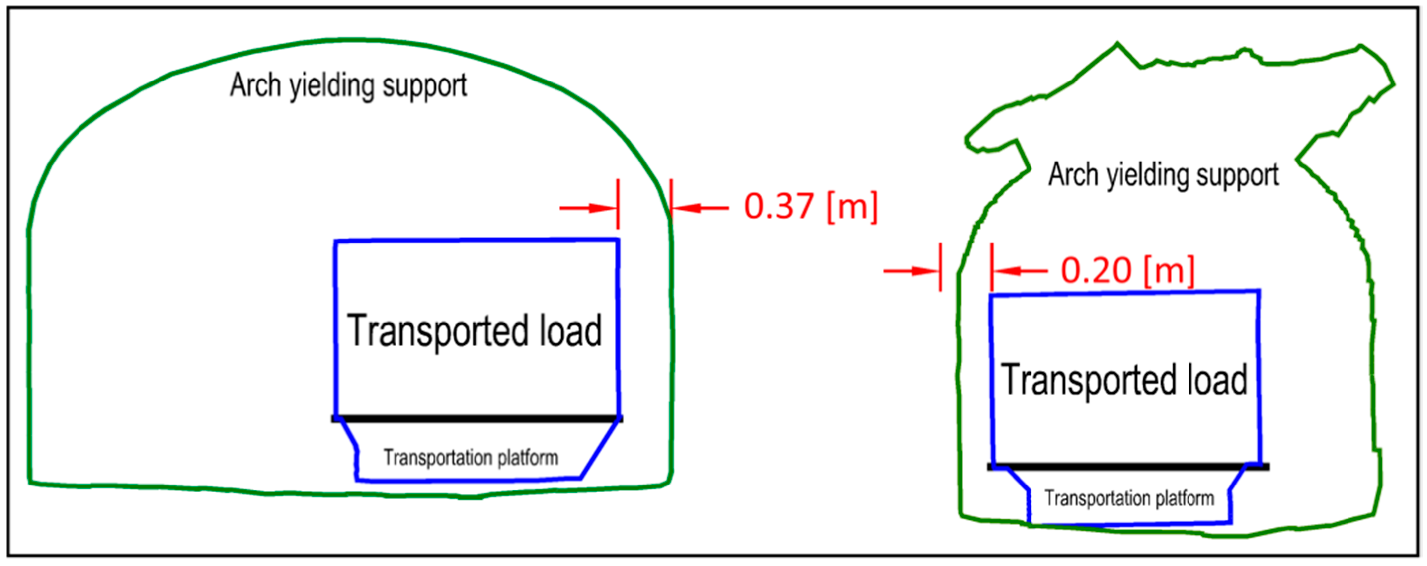
Another way of identifying the areas of potential collision is to create cross-sections of underground working, containing the trace of transported load and a transportation device. Then the created cross-sections can be exported to CAD software, in order to dimension them. At this stage, the traffic clearances can also be taken into account. This is shown in
Figure 6, for selected cross-sections. The figure shows two cross-sections of the underground working (arch yielding support marked by green line) with the transportation platform and the transported load (blue line). The required value of the traffic clearances was taken into account by drawing the outer red contour of the transported load, together with the transportation platform. The obtained cross-sections were dimensioned, and—on the bottom of the floor—the place on which the load is placed (thick black line) was marked.
Figure 6b shows the places of measurement of traffic clearances (A and B). Additionally,
Figure 6a,b show the black hatched area (below the upper surface of the transportation platform) that is not the subject of the collision analysis when transporting by floor-mounted railway (the load is placed on the transportation platform).
The output from STAGE 3 is: the identified areas of potential collision; cross-sections of underground working, containing: the supports, the existing infrastructure of the working (pipelines, belt and scraper conveyors, road machines, etc.) and the trace of the transported load.
2.4. Redesigning Process (STAGE 4)
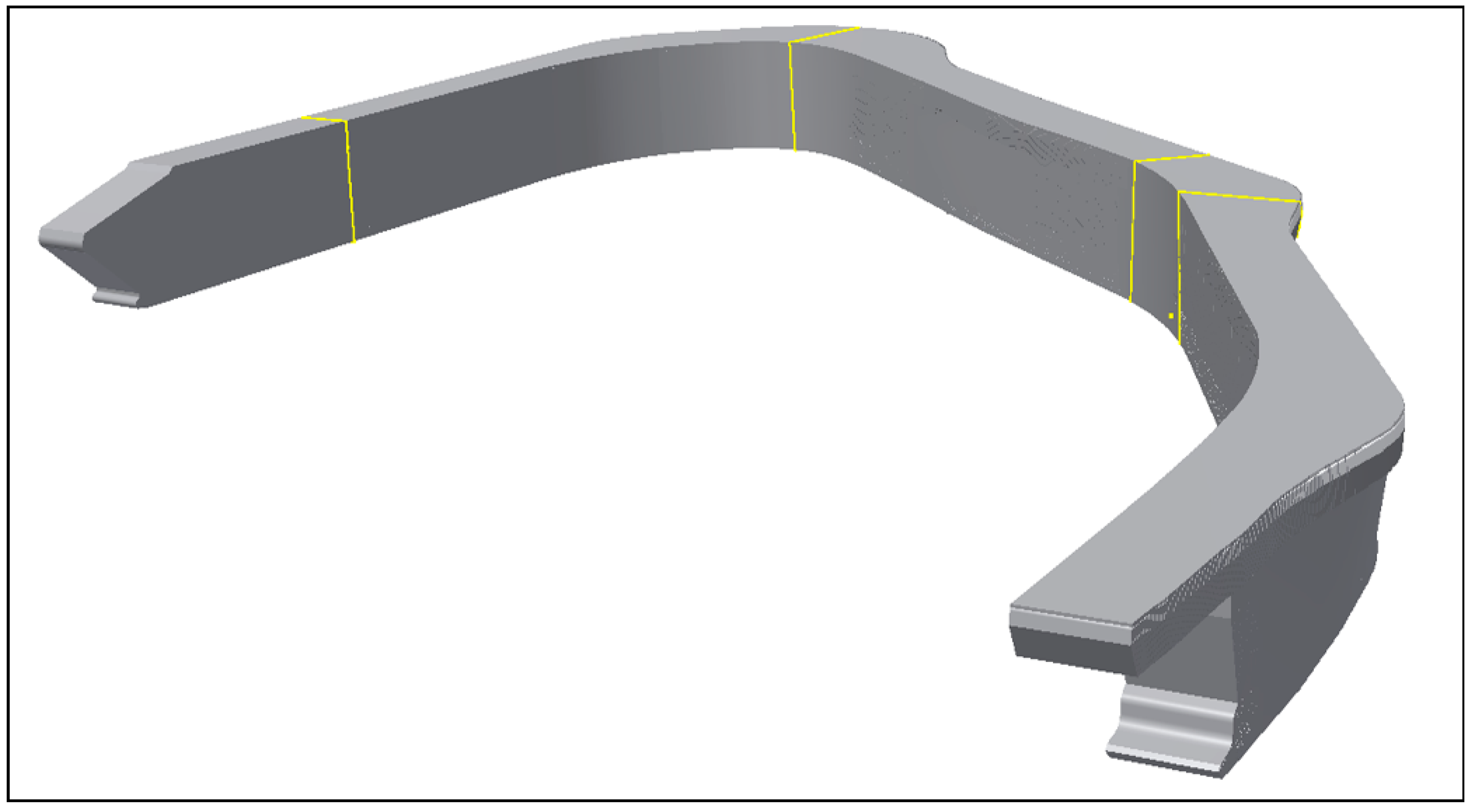
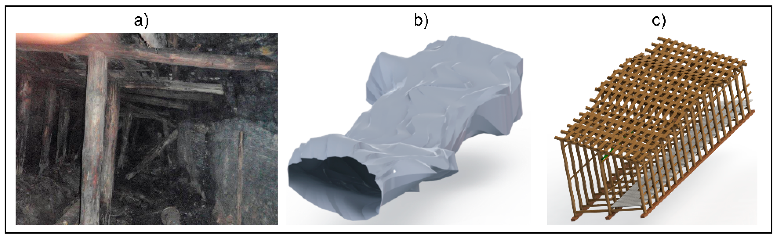
Three-dimensional scanning of mine underground workings is a useful measurement method, especially in the case of design regarding supports of underground workings with complex geometry. An example may be underground workings in historic mines that are available for tourists. In addition to ensure an appropriate, high level safety of visitors, the underground workings must meet the requirements of the conservator. At the same time, the supports used in the underground workings have to adapted to the their current cross-sectional shape. Such a situation took place in the case of designing the supports for the main gallery in seam 510 in the Historic Coal Mine GUIDO in Zabrze (Poland), as shown in
Figure 7.
3D scanning is widely used in the case of communication nodes in mines, e.g., underground crossroads. It allows for geodetic inventory of the mine working, and—in combination with the modeled trace of transportation means and transported materials—enables to keep appropriate traffic clearances and avoid possible collisions. The combination of the trace of the transported materials and the outline of the workings within CAD software tool allows for proper selection of the arch yielding supports for specific mine underground workings as well as proper (matching the actual dimensions) design of supports for the underground crossroads.
The output from STAGE 4 is custom-made new designed underground working support.
2.5. Visualizations of the Results with the Use of Virtual Reality (STAGE 5)
Currently, the visualization process is no longer applied just to show the finished product or technical solution variants but is also an integral point in the design process. It becomes possible thanks to the constantly developing methods of visualization, the increasing speed of data processing, and close to the real visual quality of the presentation [
20,
21]. Thanks to evolving software solutions available for desktop computers, preparing an additional version of the 3D model strictly for visualization is not necessary—the whole process may base on the same data without the necessity to simplify the 3D model. Evolving high-quality visualization significantly improves the product/process reception and allows to test various (not only purely visual but also functional) aspects of the solution at once [
22]. Additionally, growing accessibility and affordability of Virtual Reality solutions, in particular the ‘immersive’ ones, provides additional, useful possibilities to analyze the 3D models reflecting the objects being designed or redesigned.
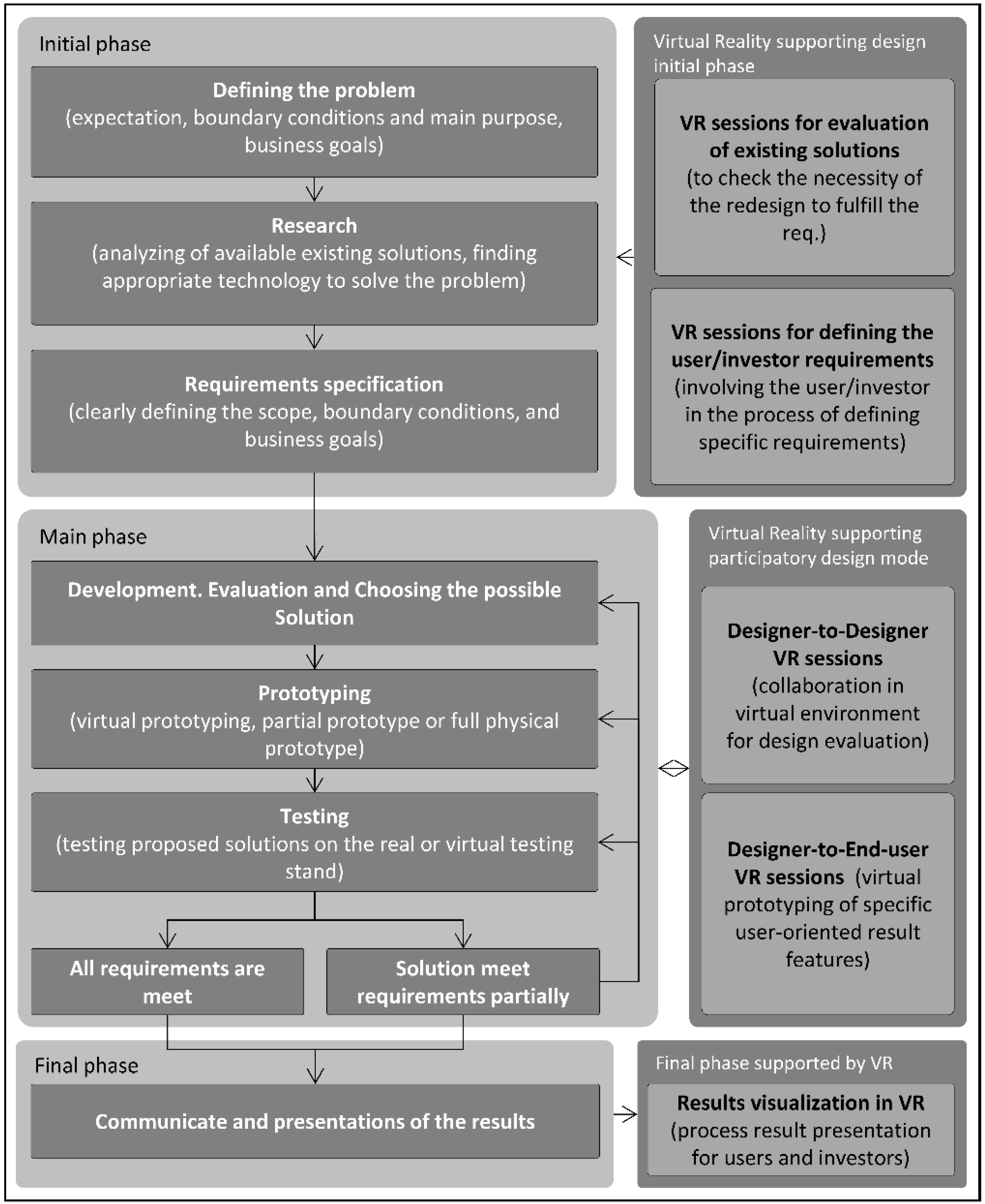
The general possibility to use VR technology as a support for typical design approach is presented in
Figure 8.
Virtual technology may be useful in all phases of the design (or redesign) process [
23]. Each phase may be supported in a different way [
24]. VR session may be used as a tool for collecting information (Virtual Reality supporting design initial phase), for idea evaluation (Virtual Reality supporting participatory design mode), and for presenting results (Final phase supported by VR) [
25]. The implementation of the virtual reality solutions, using head and hands tracking and head-mounted display (HMD), gives users full immersion and possibilities to interact with the presented objects.
An important aspect that allows increasing the area of possible VR applications is the availability of hardware and software that allow for easy implementation of advanced VR methods. In some areas of VR application—e.g., entertainment/games, teaching/training programs—the hardware part cooperates with specialized software, prepared for a specific type of application. Such an approach gives a high-quality solution, but in case of changes, updates, or extensions needs, it is necessary to involve external parties, which is not always possible taking into consideration the cost. As a result, a high-quality product is obtained, but with no practical potential for modifications, e.g., update, upgrade. Both cost and flexibility regarding introducing changes in the content presented with use of VR are particular important aspect in design. Design is a creative process in which iterations take place—particular stages (individually or several subsequent ones) are repeated, revised to obtain the desired results. And as condition for application of VR in design process, it should be established, that it is impossible to finance involvement of third parties for reflecting subsequent design updates as VR content. Therefore, approach according to which designers use a palette of ready-made tools that provide relevant functionalities (e.g., allowing manipulation of objects in the spatial environment) useful for analysis and discussion of any 3D model and enable changing of these models (update of the VR content) by designers on their own [
26,
27] should be developed and followed.
During the design process, starting from the development of concept, through development, evaluation and comparing of design versions, up to the final stage of the design process, VR technology may be used as a supporting tool for all parties involved in the process, both from the design team and from clients, decision makers etc. The sample evaluation process of the design concept is presented in
Figure 9.
Being immersed in the VR world, the user can observe a 3D model in a real scale, which is crucial for detecting possible design problems and helps to identify the problematic aspect of future use of the designed system. Depending on virtual reality software used, the process may be passive (only observation and navigation inside the scene with 3D model/s) or active (identified problematic elements, may be marked by adding graphical elements, e.g., 3D models reflecting machine parts or equipment, or textual notes).
3. Implementation of the Method
In the presented example (transportation process), the results of 3D scanning of the existing underground working in the Premogovnik Velenje mine (Velenje, Slovenia) were used. 3D simulations of transportation process were carried out in CAD software tool (AutoCAD). Application of Virtual Reality improved and enhanced the interpretation of the obtained results.
3.1. Description of the Transportation Task
The design of the transportation route should be verified. If necessary, the existing underground working should also be redesigned (e.g., its cross-sections should be adapted to the transported load). Below, assumptions regarding the task—in the context of application of the presented method—are described.
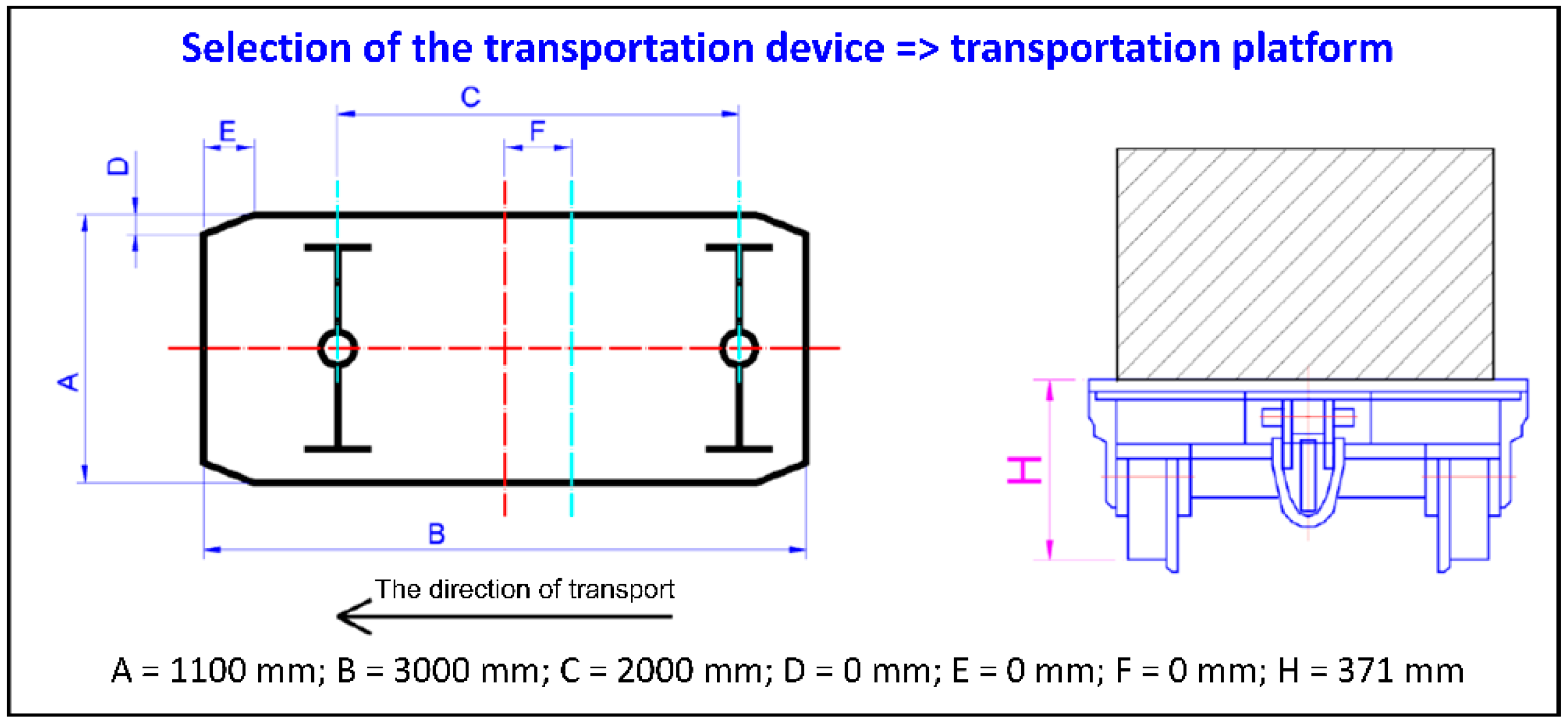
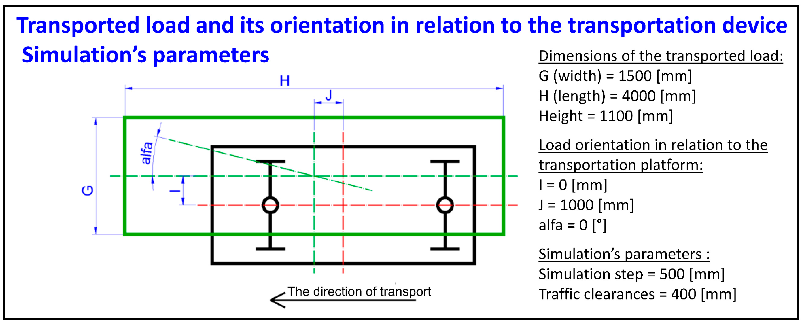
For the purpose of analysis, a part of the underground working that contains a transportation route for the floor-mounted railway was selected. A big-size load with dimensions: 4000 mm (length) × 1500 mm (width) × 1100 mm (height) was selected to be transported. A power roof support was the transported load. Transport from point A to point B was selected—starting and ending point for the transportation were defined. A transportation platform with the following dimensions was used: length = 3000 mm, width = 1100 mm, track spacing = 500 mm, wheelbase of wheelsets = 2000 mm. For the purposes of the analysis, it should be assumed that the gravity center of the load should be above the geometrical center of the transportation platform. In this particular case, the geometrical center of the 3D model of the power roof support was moved forward by a value of 1000 mm in relation to the geometrical center of the transportation platform. It should be also assumed that there is no asymmetry in the distribution of the load along the width of the transportation platform (the geometric center of the transportation platform and the load lie on one axis). There is also no rotation of the transported load in relation to the transportation platform. The distance between successive traces of the load (simulation step) should be 500 mm (preliminary determination of the 3D trace of the load), while the size of the traffic clearances should be 400 mm (resulting from the regulations). The distance between successive traces of the load (simulation step) is the value by which the load will move along the route, while the size of the traffic passages is the minimum distance from the external dimensions of the load to potential obstacles on the transportation route. The height of the transportation platform (load placement height from the rail head) should be 371 mm.
Subsequent stages of the task realization, following the presented method, are discussed in the next sections.
3.2. 3D Scanning (STAGE 1)
View of raw 3D scan of the selected area of the mine underground working (point cloud containing 23 million of points), covering the area: 202 [width] × 297 [length] × 19 [height] [m], was presented in
Figure 10. For the future analysis, a part of the underground working (red marked area, length about 18 [m]) was selected, containing a transportation route for the floor-mounted railway. For each of the rails, the coordinates of its vertices were read and then saved to a text file that was the input data for STAGE 2.
3.3. Computer Simulations (STAGE 2)
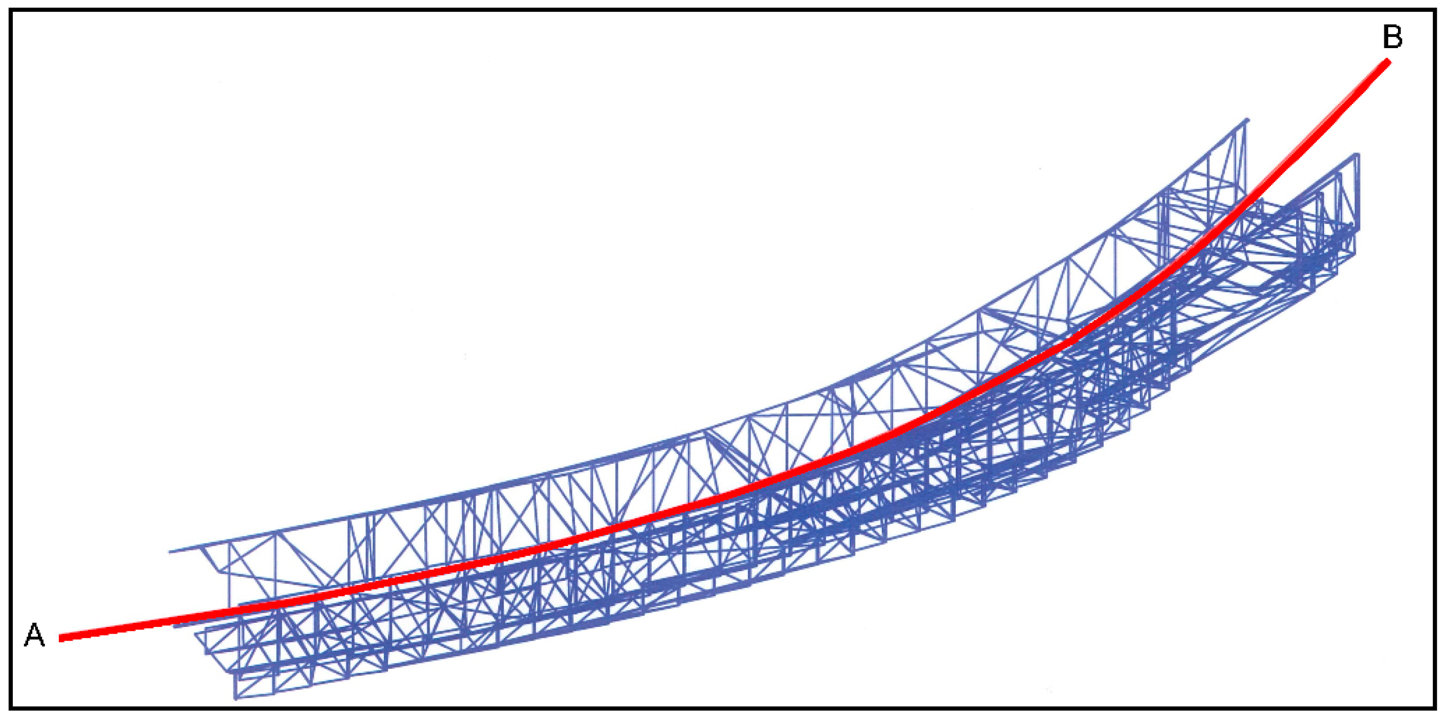
Within CAD software, on the basis of rails’ coordinates, an axis of the route was determined (red line), together with the direction of transport (transportation task),
Figure 11.
On the basis of the transportation task, a CAD simulation model was built, consisting of the transportation device (transportation platform,
Figure 12) and the transported load. The transported load was oriented in relation to the transportation platform, and the simulation’s parameters (simulation step and traffic clearances) were established,
Figure 13.
During the simulation, the transportation device with the load moves along the route (from point A to point B) with the given simulation step. In each simulation step, the location of the transportation device with the load is determined. After each simulation step, a trace of the transported load is marked (with no traffic clearances and with given traffic clearances). After completing the simulation, 3D traces of the load along the route are obtained,
Figure 14. Then, exported as an OBJ file (3D Object File), they are the input data for the next stage.
3.4. Identification of Areas of Potential Collision (STAGE 3)
Combining the results, obtained from the 3D scanning (scan of the selected area of underground working—STAGE 1) with the CAD simulation (trace of the transported load—STAGE 2) in one software environment (CloudCompare) allows to obtain one 3D model, for the purpose of analysis of collision possibility,
Figure 15. The common element from STAGE 1 and STAGE 2 is the rail route.
For the purposes of the collision analysis, the 3D trace of the transported load was converted into a point cloud. Then, having two clouds of points: the underground working with its equipment (reference cloud) and the trace of transported load (compared cloud), the tool ‘Cloud-to-Cloud Distance computation => nearest neighbor distance’ in the CloudCompare software was selected. The result is shown as colored map of distances, where every point from compared cloud is colored according to its distance to reference cloud. At this point, a visual evaluation of the areas of the underground working can be carried out, where collision may occur during carrying out the transportation (red marked areas).
In
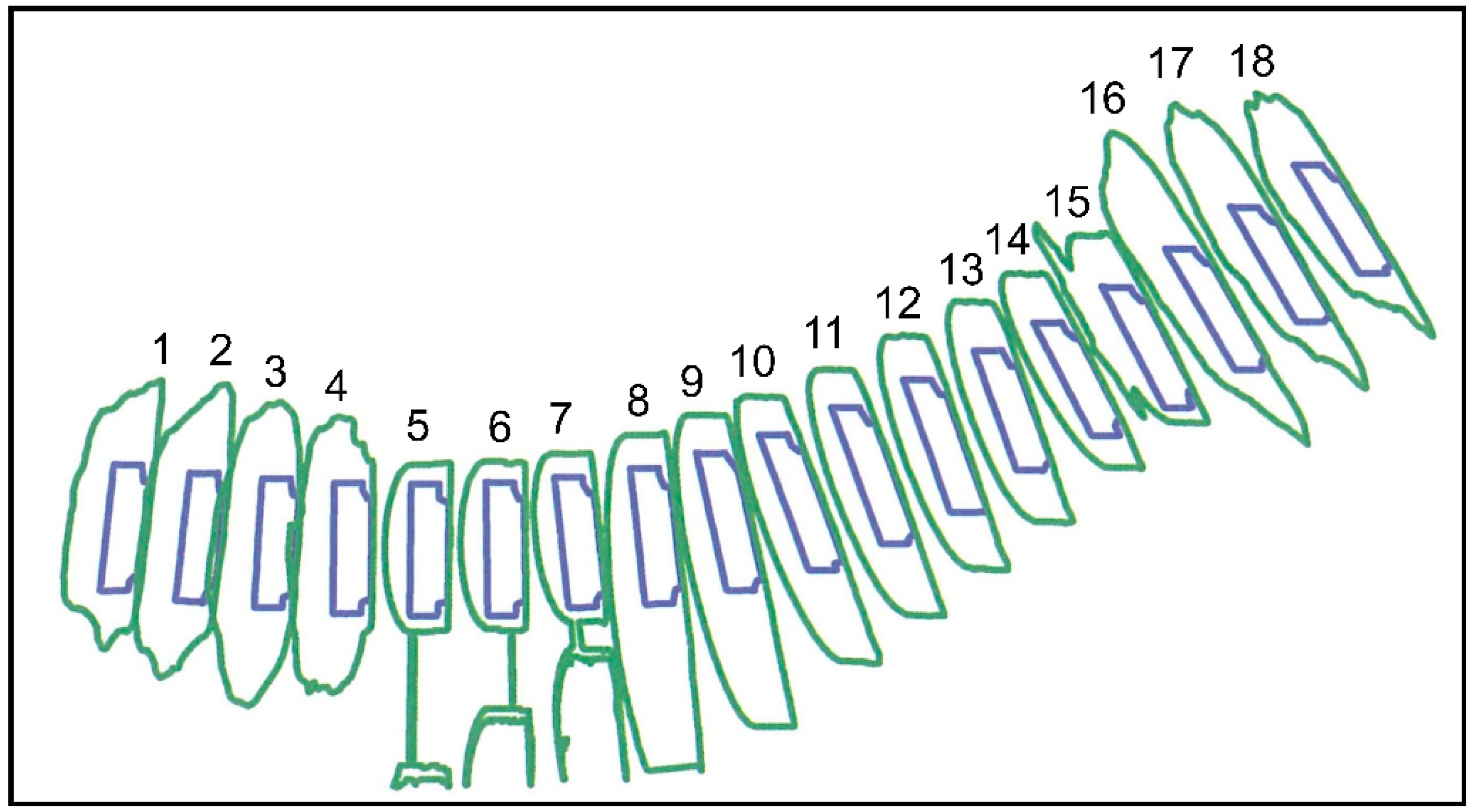
Figure 15, distance between cross-sections of the underground working equals 1 m. The cross-sections included both the arch yielding support of the underground working (green line) and the trace of transported load, without traffic clearances (blue line).
Figure 16 shows these cross-sections (18 in total). Then, the selected cross-sections (where collision may occur or where traffic clearances are not preserved) were exported to CAD software to dimension them,
Figure 17.
3.5. Redesigning Process (STAGE 4)
The analysis conducted for selected cross-sections allows to state that it is not possible to maintain the established values of traffic clearances (0.4 [m]) for the given transportation task. It is necessary to reconstruct parts of the underground working, change the location of the route of the floor-mounted railway or transport load in parts.
An example of redesigning the selected area of an underground working, is the portal branch casing project [
28,
29,
30] for the connection of crossover of workings. The obtained scans allowed for the redesign that is optimal in terms of the required dimensions and ensuring appropriate traffic clearances.
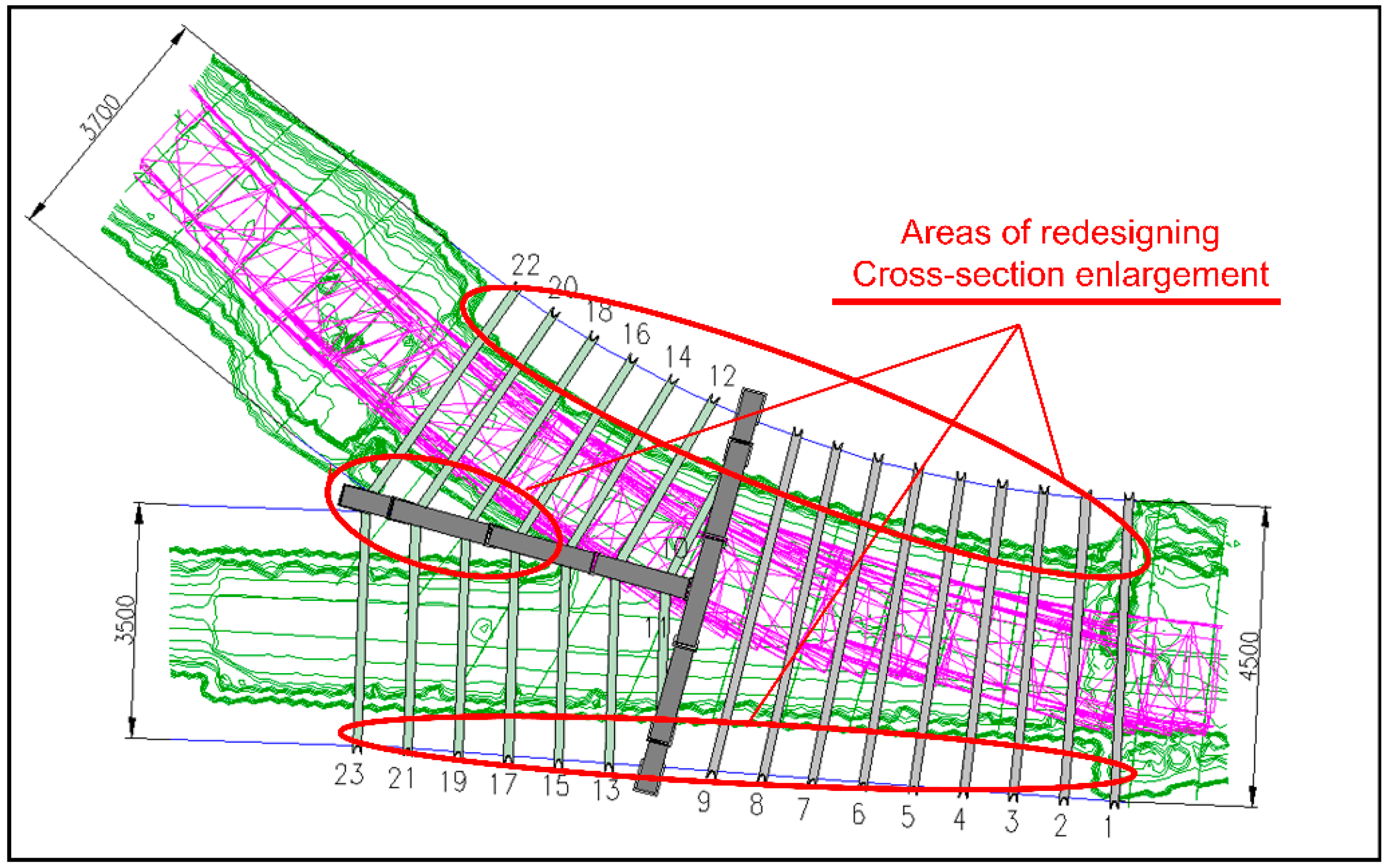
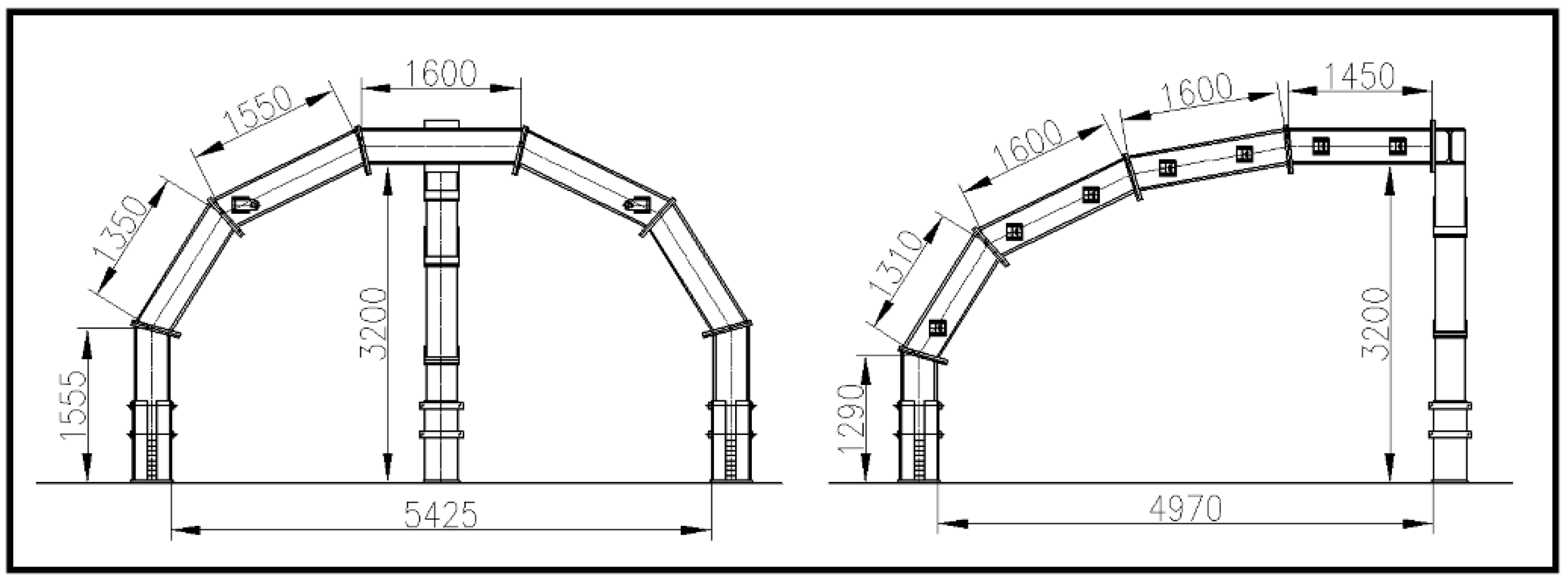
Figure 18 shows the outline of the excavation working, ensuring the appropriate traffic clearances, developed on the basis of a 3D scan of the connection of the workings, together with the outline of the designed portal and the areas of redesigning.
The cross-road support was designed as a portal stretched over the connecting workings and a cantilever located in a plane perpendicular to the portal, containing the line of intersection of the workings outlines. The portal consists of five HEB360 beams butt-twisted together, while the cantilever—four beams. Both the portal and the bracket are equipped with fusing segments with the use of wooden inserts. The skeleton structure of the branch casing—portal and cantilever are shown in a simplified way in
Figure 19.
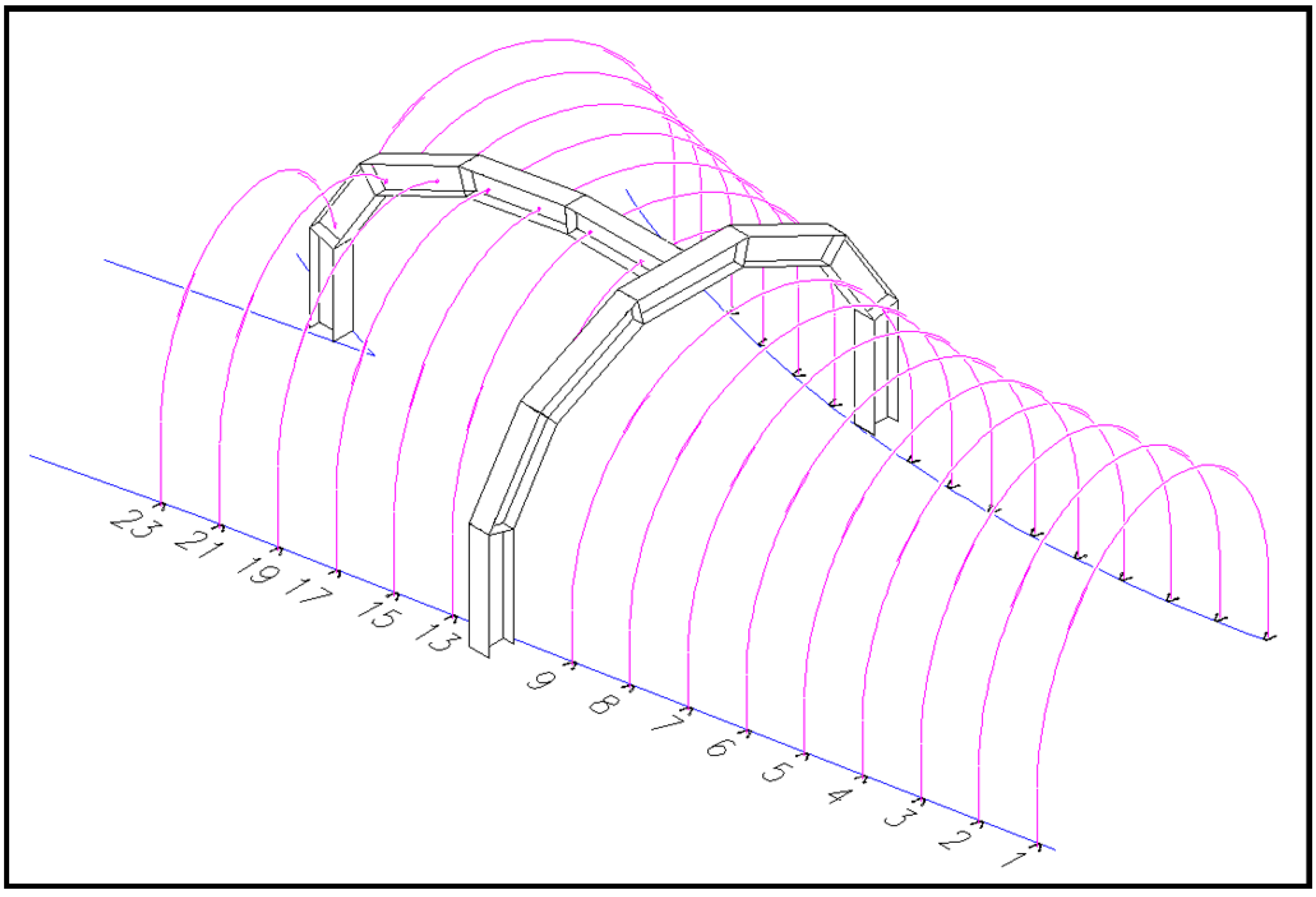
This structure is complemented by 23 V25-section arches of variable geometry, individually designed taking into account the geometry of the working obtained from scanning. Some of these arches are connected by means of cantilever, and the rest allow to connect to the existing working support.
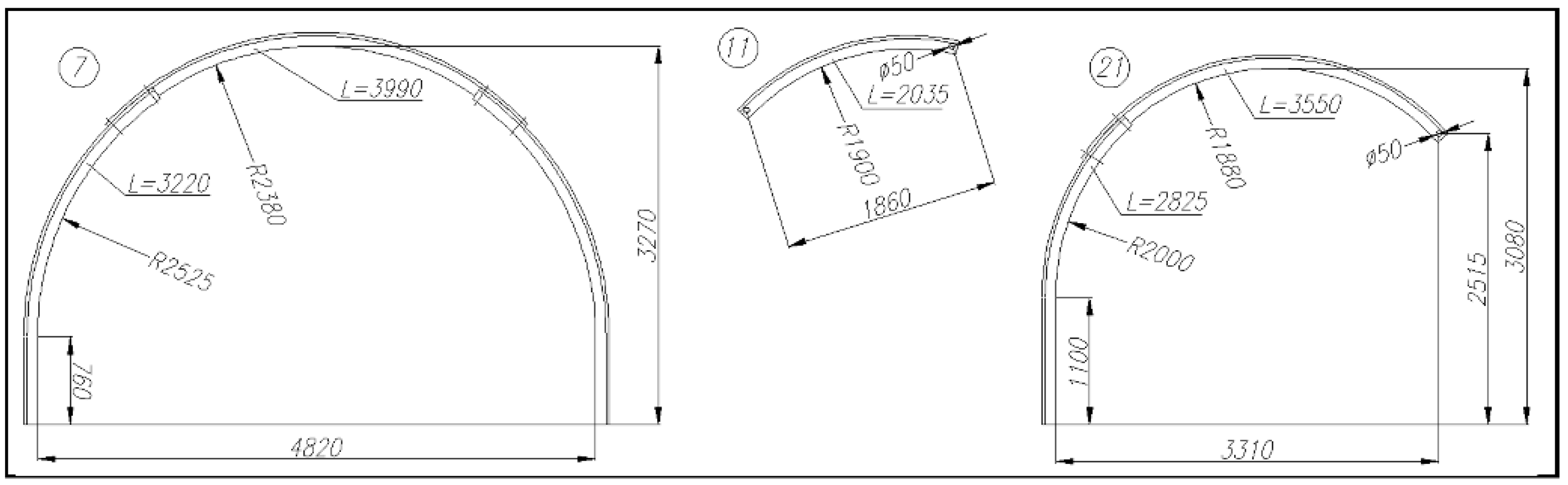
Figure 20 shows an example of customization of arch yielding support, and
Figure 21 simplified view of completed support of underground transportation cross-roads.
3.6. Visualizations of the Results (STAGE 5)
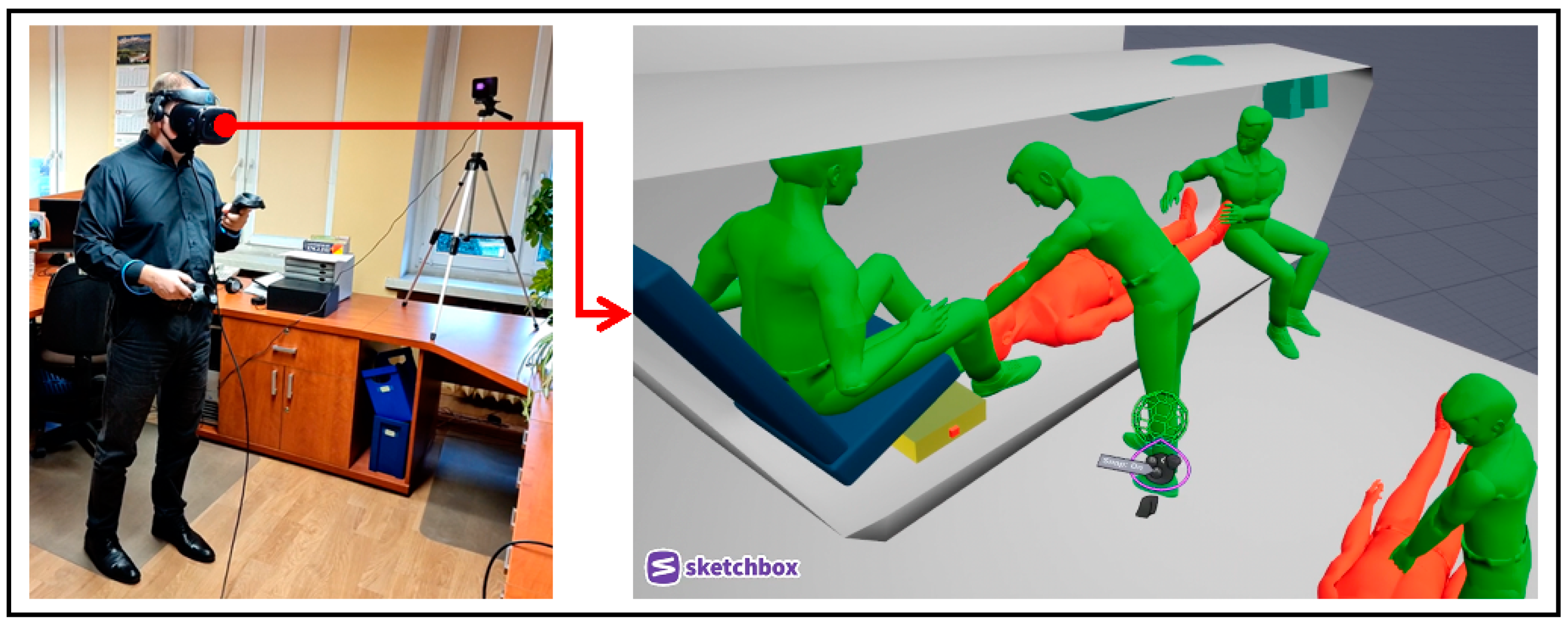
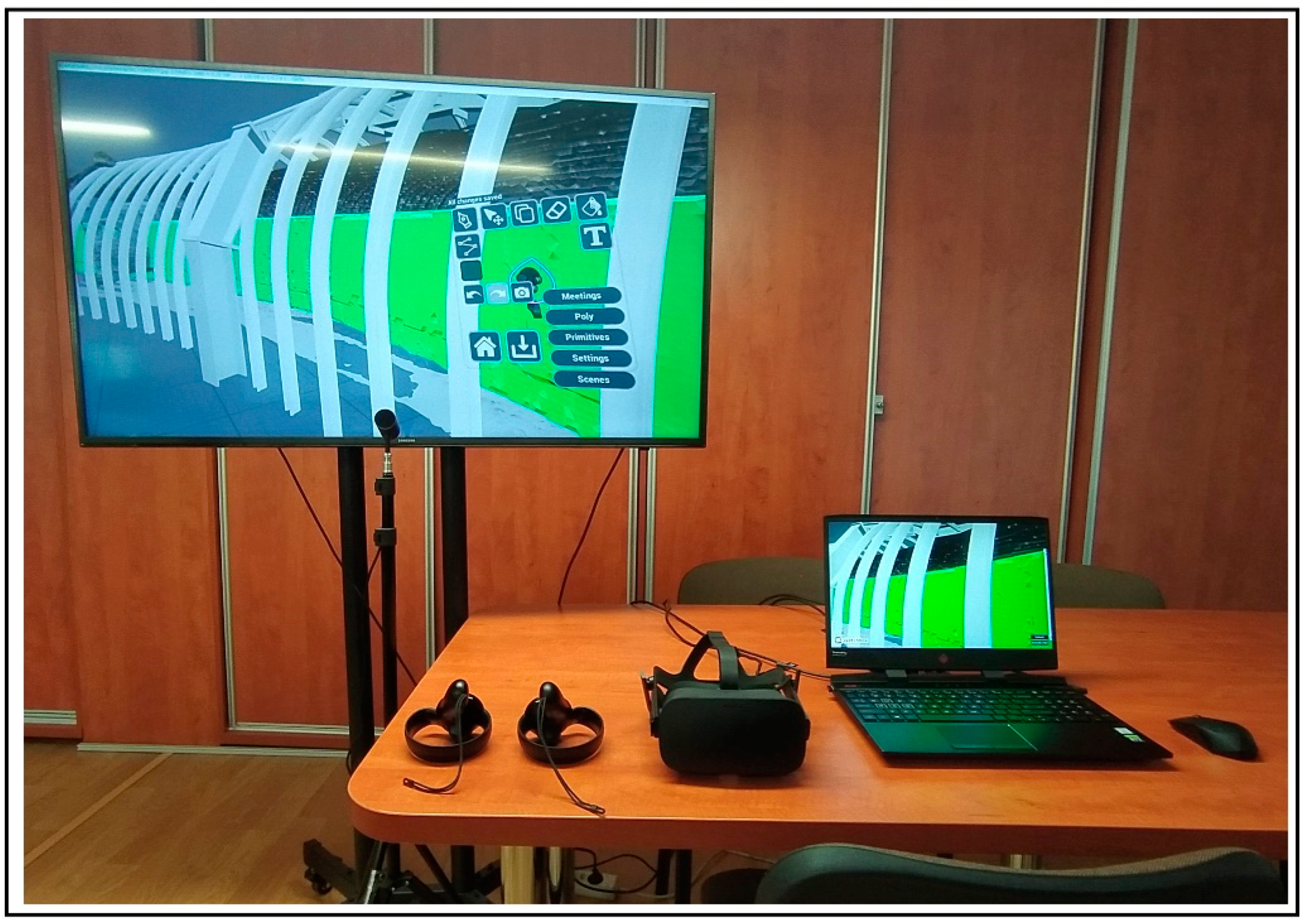
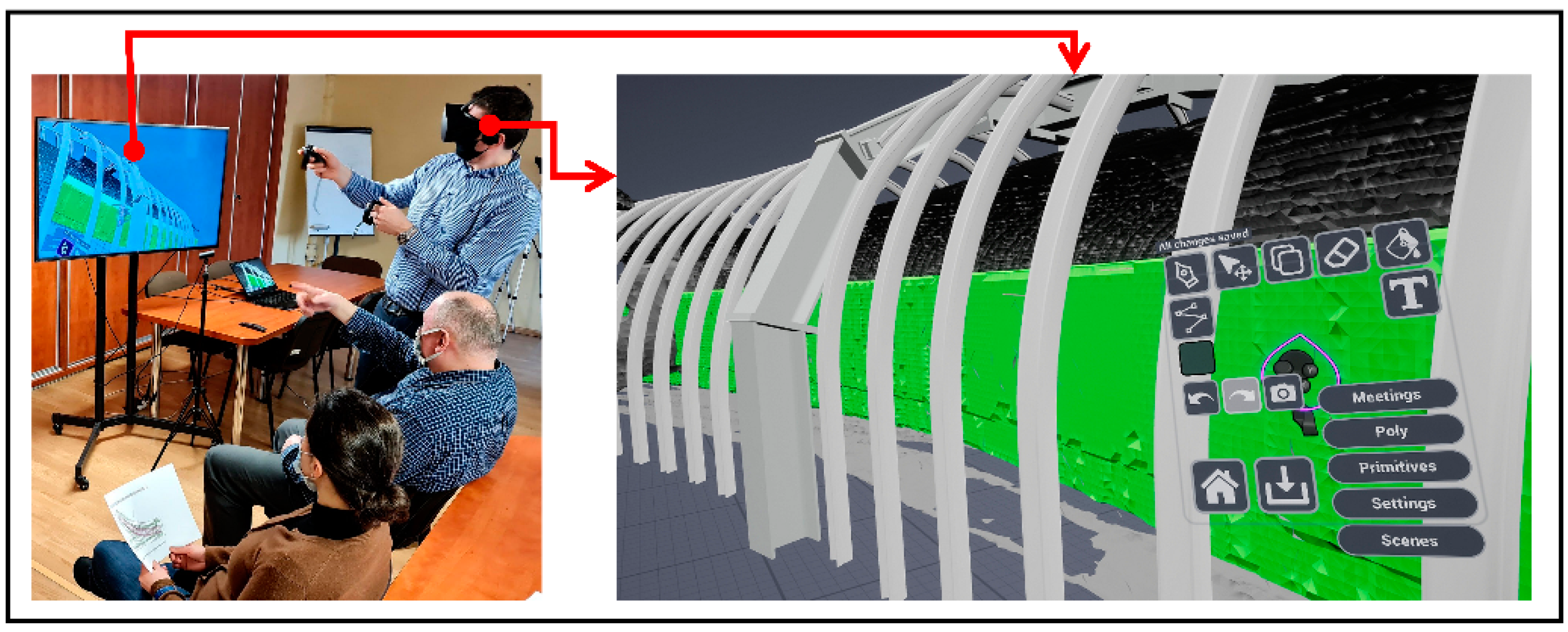
Visualizations of result and discussion based on Virtual Reality presentation was performed on VR stand equipped with computer (main element of the system to run the 3D scene along with all the uploaded models), Oculus VR googles (for immersion in the 3D scene to understand the results), manipulators (for easy navigation in the scene and adding notations and measurement), TV screen (to involve in the process also persons not wearing the 3D googles). All elements of a VR stand are presented in
Figure 22.
Equipping VR stand with a big screen is crucial for showing the same content as in the VR goggles enabling discussion of a group of interested persons and common work on the design (analysis, immediate adding annotations, placing 3D objects to express some ideas regarding design modification etc.). To display the 3D scene and interactively evaluate the redesign results, Sketchbox software environment was used. The organization of the VR session focused on design of a transportation route is presented in
Figure 23.
Thanks to functionalities provided by the Sketchbox software is possible to view and navigate around the scene. The scene consists of all 3D elements used in the redesign process, placed in a superposition to assess the design results, according to boundary conditions and expected process/construction improvements.
4. Discussion
Presented method was tested for the operating conditions of a real crossroad, located in Premogovnik Velenje mine (Slovenia).
- (1)
3D laser scanning
Using a 3D laser scanner allows to obtain a precise, virtual copy of underground working. Scanning was performed using a handheld 3D scanner. It is burdened with a greater error compared to stationary scanners. These errors are visible in the form of irregular shapes of particular cross-sections of an underground working (
Figure 16 and
Figure 17). Equipment located in a given underground working may also affect the irregularity of the underground workings contour shape.
- (2)
Computer simulations
Computer simulations, based on the input data from transportation task, were performed in AutoCAD software. They allowed to determine the trace of the transported load (
Figure 15), taking into account the required values of the traffic clearances. Then, for the purpose of future collision analysis, the trace of the transported load has been converted to a point cloud.
- (3)
Identification of areas of potential collision
By exploiting both data sources simultaneously (point cloud obtained from scanner and point cloud being the trace of transported load), it was possible to localize the areas of possible collision, create and dimension cross-sections in the CAD software (
Figure 17). To maintain the desired values of traffic clearances (and to avoid the possibility of collision), it was decided to redesign (to enlarge cross-sections) the selected area of the underground working.
- (4)
Redesigning process and visualization of the results
The main objective of the redesigning of the selected area of underground working was to enlarge the area of selected cross-sections (and thus obtain a collision free transportation) and strengthening of the existing underground working. By using the Virtual Reality, it was possible to interactively evaluate the results and find errors made during the redesigning process.
5. Conclusions
3D scanning technology is used at different stages of the product lifecycle and at different process realization steps. It can be applied e.g., in design—as a method for digitalizing a part of an existing system to collect data necessary for design other parts of the system. It can be also used for monitoring of dimensional changes (identifying the deformation or displacement) of a system to take proper decisions in time, in particular to carry out redesign process of the system or processes carried out there. Collision detection is key problem in design or redesign of a system and processes carried out there that can be realized with use of 3D scanning. Even now, in mining plants, to carry out collision analysis a two-dimensional, paper documentation of the underground working is used. On this documentation the axis of the route is marked with a sketch of the transported load. More common solution is preparing similar collision analysis with the use of CAD system.
The proposed method gives the possibility to trace the object behaviors during its motion and represent it in a form of complex 3D objects, which also represent the object kinematics. There are no ready to use hardware and/or software tools that may be applied for such specific task in underground transportation. 3D scanning allows to identify the actual geometrical dimensions of the selected area of an underground working, along with the existing infrastructure (pipelines, belt and scraper conveyors, road machines, etc.). Computer simulations, carried out in the CAD/MBS software environment, allow to determine the 3D trace of the load transported with the selected transportation device, taking into account the required size of the traffic clearances. In this way, designing of underground road crossing area is based on the actual geometrical data of the mine underground workings, which contributes to the minimization of the possibility of design errors that otherwise could occur.
The use of laser scanning allows for the accurate reproduction of the current geometrical features of transportation routes in coal mines. With use of 3D scanner software or point cloud processing software, it is possible to further process the point cloud obtained from the scanner, convert it into a surface mesh and save it in the graphic data exchange format of CAD programs.
Taking into account the actual geometrical features of the underground working is crucial at the stage of verifying the existing route of the transportation system e.g., while planning a particular transportation process. Acquiring high-accuracy geometrical features of underground working is possible using 3D laser scanning. The possibility of carrying out 3D virtual collision analyzes at this stage reduces the risk of collisions during transportation operations, in particular when transporting large-size materials in such locations as: bends, intersections and in parts of underground working where reduction of area of roadway cross-section is a result of impact of surrounding rock mass.
Applying virtual reality in the design process allows to work with virtual representations of the designed objects (machinery, systems, locations etc.) in a way that enhances and expands the possibilities you have once you work with 3D models in CAD/MBS systems.
As a follow-up activity, the proposed method will be commercialized by its application to redesign the chosen areas of underground workings in Polish coal mining industry. It should be emphasized that the implementation of the proposed method in the daily practice of the mining plant will significantly increase the work efficiency of the engineering staff involved in the maintenance of mining transport.
Author Contributions
Methodology: introduction, M.R. (Magdalena Rozmus); proposed method, writing—review and editing, J.T.; Virtual Reality, discussion and conclusions, D.M.; writing—original draft preparation, computer simulations, M.D.; CloudCompare processing software, identification of areas of potential collision, K.S.; redesigning process, M.R. (Marek Rotkegel); 3D laser scanning, formulation of transportation task, A.L. and J.R. All authors have read and agreed to the published version of the manuscript.
Funding
This research was co-funded by Erasmus+ programme of the European Union, contract number: 2020-1-PL01-KA202-082180, project MOTIV-e: “Methods, tools and resources for efficient and engaging ICT- enhanced teaching within VET”. The APC was founded by KOMAG Institute of Mining Technology.
Institutional Review Board Statement
Not applicable.
Informed Consent Statement
Not applicable.
Data Availability Statement
Not applicable.
Acknowledgments
A part of the presented work was carried out under project MOTIV-e: “Methods, tools and resources for efficient and engaging ICT- enhanced teaching within VET”, co-funded by the Erasmus+ programme of the European Union, contact number: 2020-1-PL01-KA202-082180. The European Commission’s support for the production of this publication does not constitute an endorsement of the contents, which reflect the views only of the authors, and the Commission cannot be held responsible for any use which may be made of the information contained therein.
Conflicts of Interest
The authors declare no conflict of interest.
References
- Tokarczyk, J. Zagrożenia i ich skutki występujące w pomocniczym transporcie podziemnych zakładów górniczych. In Methodology for Identifying the Selected Mechanical Hazards in Auxiliary Transport of Underground Mines; KOMAG Institute of Mining Technology: Gliwice, Poland, 2017; Monograph No. 52; pp. 19–23. ISBN 978-83-65593-08-5. (In Polish) [Google Scholar]
- Tokarczyk, J.; Dudek, M.; Gicala, B. Safety-oriented virtual prototyping of mining mechanical systems. In Handbook of Loss Prevention Engineering; Joel, M.H., Ed.; Wiley-VCH Verlag GmbH & Co. KGaA: Weinheim, Germany, 2013; Volume 2, pp. 445–462. [Google Scholar]
- Tokarczyk, J.; Michalak, D.; Rozmus, M.; Szewerda, K.; Żyrek, L.; Železnik, G. Ergonomics Assessment Criteria as a Way to Improve the Quality and Safety of People’s Transport in Underground Coal Mines. In Advances in Ergonomics in Design. AHFE 2019; Rebelo, F., Soares, M., Eds.; Springer: Cham, Switzerland, 2020; Volume 955, pp. 305–317. [Google Scholar] [CrossRef]
- Shellshear, E.; Tafuri, S.; Carlson, J. A multi-threaded algorithm for computing the largest non-colliding moving geometry. Comput. -Aided Des. 2014, 49, 1–7. [Google Scholar] [CrossRef]
- Dudek, M. Use of CAD Systems in Testing the Collision of Underground Transportation Means. Arch. Min. Sci. 2013, 58, 411–432. [Google Scholar] [CrossRef]
- Ristovic, I.; Vulic, M. Affordable Photogrammetry as Applied in the 3D Modelling and Monitoring of Underground Mining Exploitation and Transport. Appl. Mech. Mater. 2014, 683, 251–256. [Google Scholar] [CrossRef]
- Helle, R.H.; Lemu, H.G. A case study on use of 3D scanning for reverse engineering and quality control. Mater. Today Proc. 2021, in press. [Google Scholar] [CrossRef]
- Michalak, D.; Gomez Herrero, J.A. Innovative solutions need an innovative approach–3D printing technology, example of use and conclusion from implementation in an organization. Min. Mach. 2020, 162, 48–57. [Google Scholar] [CrossRef]
- Gargoum, S.A.; Karsten, L. Virtual assessment of sight distance limitations using LiDAR technology: Automated obstruction detection and classification. Autom. Constr. 2021, 125, 103579. [Google Scholar] [CrossRef]
- Jiang, W.; Zhou, Y.; Ding, L.; Zhou, C.; Ning, X. UAV-based 3D reconstruction for hoist site mapping and layout planning in petrochemical construction. Autom. Constr. 2020, 113, 103137. [Google Scholar] [CrossRef]
- Xu, J.; Ding, L.; Love, P.E. Digital reproduction of historical building ornamental components: From 3D scanning to 3D printing. Autom. Constr. 2017, 76, 85–96. [Google Scholar] [CrossRef]
- Price, L.C.; Chen, J.; Park, J.; Cho, Y.K. Multisensor-driven real-time crane monitoring system for blind lift operations: Lessons learned from a case study. Autom. Constr. 2021, 124, 103552. [Google Scholar] [CrossRef]
- Wang, W.; Zhao, W.; Huang, L.; Vimarlund, V.; Wang, Z. Applications of terrestrial laser scanning for tunnels: A review. J. Traffic Transp. Eng. (English Ed.) 2014, 1, 325–337. [Google Scholar] [CrossRef]
- Kajzar, V.; Kukutsch, R.; Heroldova, N. Verifying the possibilities of using a 3D laser scanner in the mining underground. Acta Geodyn. Geomater 2015, 12, 177. [Google Scholar] [CrossRef]
- Kukutsch, R.; Kajzar, V.; Konicek, P.; Waclawik, P.; Ptacek, J. Possibility of convergence measurement of gates in coal mining using terrestrial 3D laser scanner. J. Sustain. Min. 2015, 14, 30–37. [Google Scholar] [CrossRef]
- Schauer, J.; Nuchter, A. Efficient point cloud collision detection and analysis in a tunnel environment using kinematic laser scanning and K-D Tree search. ISPRS-Int. Arch. Photogramm. Remote. Sens. Spat. Inf. Sci. 2014, XL-3, 289–295. [Google Scholar] [CrossRef]
- Eyre, M.; Foster, P.; Speake, G.; Coggan, J. Integration of Laser Scanning and Three-dimensional Models in the Legal Process Following an Industrial Accident. Saf. Health Work 2017, 8, 306–314. [Google Scholar] [CrossRef]
- Schauer, J.; Nüchter, A. Collision detection between point clouds using an efficient k-d tree implementation. Adv. Eng. Inform. 2015, 29, 440–458. [Google Scholar] [CrossRef]
- Rotkegel, M.; Szot, Ł.; Witek, M.; Szewczyk, B. The use of modern tools in the design of the support of the main gate in seam S10 in the Historic “Guido” Coal Mine. Wiadomości Górnicze 2015, 7–8, 387–394. (In Polish) [Google Scholar]
- Winkler, T.; Tokarczyk, J.; Michalak, D. Virtual working environment. In Handbook of Loss Prevention Engineering; Joel, M.H., Ed.; Wiley-VCH Verlag GmbH & Co. KGaA: Weinheim, Germany, 2013; Volume 1, pp. 393–421. [Google Scholar]
- Hermann, M.; Pentek, T.; Otto, B. Design principles for industrie 4.0 scenarios. In Proceedings of the 49th Hawaii International Conference on System Sciences (HICSS), Koloa, HI, USA, 5–8 January 2016; IEEE Computer Society: Washington, DC, USA, 2016. [Google Scholar]
- Rozmus, M.; Michalak, D. Computer aided shaping of safe behavior at work place. Mach. Dyn. Res. 2015, 39, 92–102. [Google Scholar]
- Wolfartsberger, J.; Zenisek, J.; Sievi, C. Chances and Limitations of a Virtual Reality-supported Tool for Decision Making in Industrial Engineering. IFAC-PapersOnLine 2018, 51, 637–642. [Google Scholar] [CrossRef]
- Oztemel, E.; Samet, G. Literature review of Industry 4.0 and related technologies. J. Intell. Manuf. 2020, 31.1, 127–182. [Google Scholar] [CrossRef]
- Winkler, T.; Michalak, D. Partycypacyjny tryb planowania montażu maszyn górniczych pod ziemią. Przegląd Mech. 2009, 7–8, 50–54. (In Polish) [Google Scholar]
- Feeman, S.M.; Wright, L.B.; Salmon, J. Exploration and evaluation of CAD modeling in virtual reality. Comput. Aided Des. Appl. 2018, 15, 892–904. [Google Scholar] [CrossRef]
- Yang, C.; Liu, J.; Chen, S.; Huang, K. Virtual machine management system based on the power saving algorithm in cloud. J. Netw. Comput. Appl. 2017, 80, 165–180. [Google Scholar] [CrossRef]
- Rotkegel, M. Portal-frame support of working junctions designed in GIG (Central Mining Institute). Przegląd Górniczy 2018, 2, 1–7. (In Polish) [Google Scholar]
- Rotkegel, M. Metoda Projektowania Portalowo-Szkieletowej Obudowy Połączeń Wyrobisk Korytarzowych; Central Mining Institute: Katowice, Poland, 2017; pp. 1–176. (In Polish) [Google Scholar]
- Rotkegel, M. Typical construction solutions of portal support of dog heading connection. Przegląd Górniczy 2013, 6, 7–16. (In Polish) [Google Scholar]
- MOTIV-e European Project: Methods, Tools and Resources for Efficient and Engaging ICT-Enhanced Teaching within VET Erasmus+ EU Programme, Contact No. 2020-1-PL01-KA202-082180. Available online: http://motiv-e.eu/ (accessed on 22 March 2021).
Figure 1.
Example of transportation of big-size load on a transportation platform.
Figure 1.
Example of transportation of big-size load on a transportation platform.
Figure 2.
Examples of point clouds, containing transportation routes.
Figure 2.
Examples of point clouds, containing transportation routes.
Figure 3.
An example of determining the location of a transportation device with a load at a given point of a route: (a) for the transportation platform (floor-mounted railway); (b) for the modular load-carrying unit (suspended monorail).
Figure 3.
An example of determining the location of a transportation device with a load at a given point of a route: (a) for the transportation platform (floor-mounted railway); (b) for the modular load-carrying unit (suspended monorail).
Figure 4.
An example of 3D trace of transported load (output from computer simulations).
Figure 4.
An example of 3D trace of transported load (output from computer simulations).
Figure 5.
An example of ‘Cloud-to-Cloud Distance computation’.
Figure 5.
An example of ‘Cloud-to-Cloud Distance computation’.
Figure 6.
Examples of cross-sections of underground working: collision-free transport (a), transport with collision risk occurrence (b).
Figure 6.
Examples of cross-sections of underground working: collision-free transport (a), transport with collision risk occurrence (b).
Figure 7.
View of the underground working with parts of a loosened wooden casing (
a), outline of the scanned area of the working (
b) and designed new underground working support (
c) [
19].
Figure 7.
View of the underground working with parts of a loosened wooden casing (
a), outline of the scanned area of the working (
b) and designed new underground working support (
c) [
19].
Figure 8.
Possibilities of applying the Virtual Reality in the design process.
Figure 8.
Possibilities of applying the Virtual Reality in the design process.
Figure 9.
Example of using Virtual Reality to edit and visualize the obtained results.
Figure 9.
Example of using Virtual Reality to edit and visualize the obtained results.
Figure 10.
View of raw 3D scan of underground working and selected part for analysis (red marked area), containing transportation routes.
Figure 10.
View of raw 3D scan of underground working and selected part for analysis (red marked area), containing transportation routes.
Figure 11.
Determined axis of the route and direction of transport: A => B.
Figure 11.
Determined axis of the route and direction of transport: A => B.
Figure 12.
Input data for development of the simulation model in AutoCAD environment—transportation device.
Figure 12.
Input data for development of the simulation model in AutoCAD environment—transportation device.
Figure 13.
Input data for development of the simulation model in AutoCAD environment—transported load and simulation’s parameters.
Figure 13.
Input data for development of the simulation model in AutoCAD environment—transported load and simulation’s parameters.
Figure 14.
Output from Computer Simulations—3D trace of transported load.
Figure 14.
Output from Computer Simulations—3D trace of transported load.
Figure 15.
3D model for the purpose of analysis of collision possibility.
Figure 15.
3D model for the purpose of analysis of collision possibility.
Figure 16.
Cross-sections of selected area of the underground working.
Figure 16.
Cross-sections of selected area of the underground working.
Figure 17.
Selected cross-sections (9 and 15) of the underground working.
Figure 17.
Selected cross-sections (9 and 15) of the underground working.
Figure 18.
The outline of the working planned for reconstruction, planned portal lining and areas of redesigning.
Figure 18.
The outline of the working planned for reconstruction, planned portal lining and areas of redesigning.
Figure 19.
The structure of the branch casing-portal and cantilever.
Figure 19.
The structure of the branch casing-portal and cantilever.
Figure 20.
Example of customization of arch yielding support.
Figure 20.
Example of customization of arch yielding support.
Figure 21.
A simplified view of completed support of underground transportation cross-road.
Figure 21.
A simplified view of completed support of underground transportation cross-road.
Figure 22.
Stand for design presentation with use of Virtual Reality [
31].
Figure 22.
Stand for design presentation with use of Virtual Reality [
31].
Figure 23.
Evaluation of the redesigning results during a VR session [
30].
Figure 23.
Evaluation of the redesigning results during a VR session [
30].
| Publisher’s Note: MDPI stays neutral with regard to jurisdictional claims in published maps and institutional affiliations. |
© 2021 by the authors. Licensee MDPI, Basel, Switzerland. This article is an open access article distributed under the terms and conditions of the Creative Commons Attribution (CC BY) license (https://creativecommons.org/licenses/by/4.0/).


 ,
, 


