
Using Heat Pumps to Improve the Efficiency of Combined-Cycle Gas Turbines


Abstract
1. Introduction
- To analyze possible sources of low-potential heat available in the cycle of heat and electricity generation at a CCGT-CHPP;
- To determine the options for using the heat obtained from a HPU to improve the performance indicators of a CCGT-CHPP;
- To propose schemes of including HPUs of various types in the scheme of a CCGT-CHPP;
- To create models of CCGT-450 power unit without and with HPU in the “United Cycle” computer-aided design (CAD) system;
- To analyze the impact of HPUs’ inclusion in the scheme on the efficiency of a CCGT-CHPP.
2. Materials and Methods
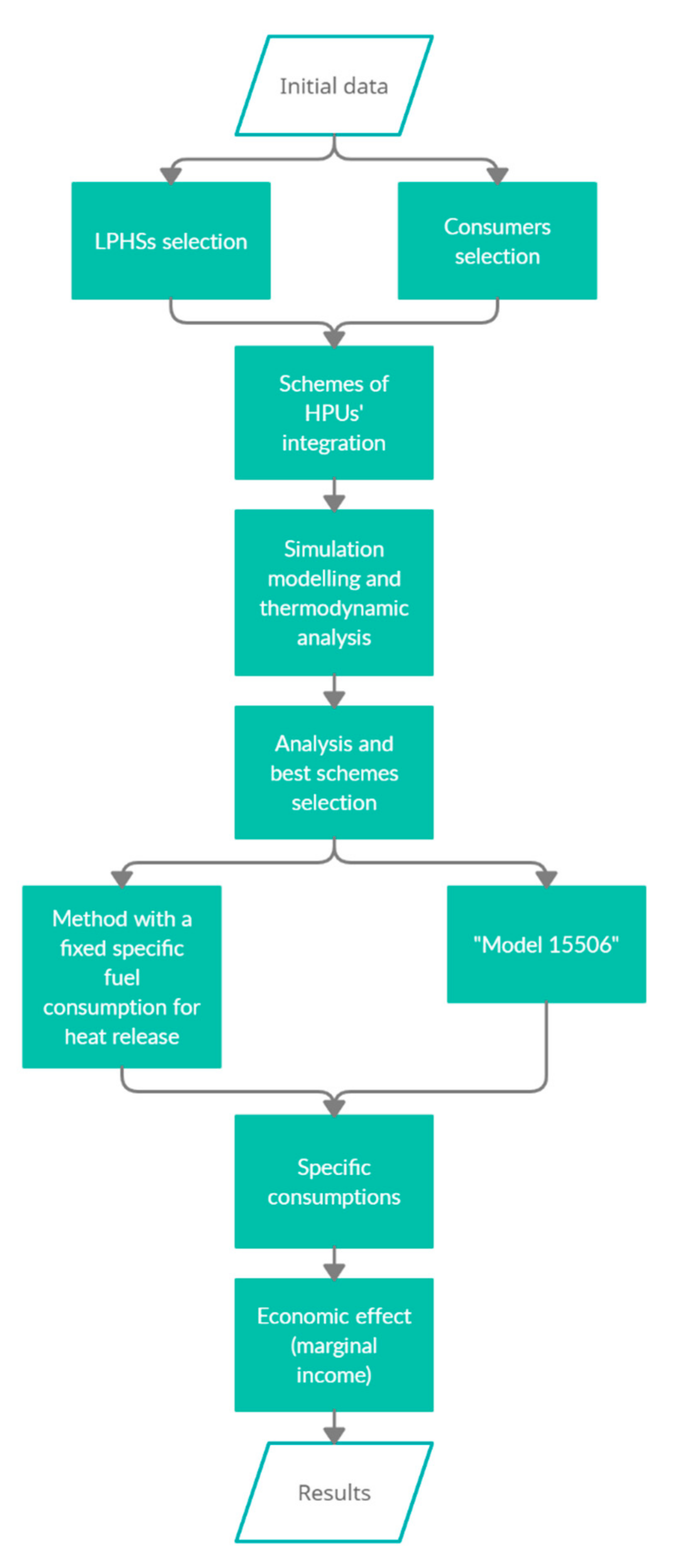
2.1. Research Algorithm
- thermal and technological schemes of systems and subsystems of CCGT-CHPP;
- normative and technical characteristics of the main and auxiliary facilities;
- operating modes maps for turbines and boilers;
- assessment of equipment;
- calculated and reference data for a steam turbine (heat balances);
- facilities operation manuals;
- daily lists and statistical information on the operating modes of a plant (duration and parameters);
- theoretical and practical methods for calculating the specific consumption of equivalent fuel, suitable for use at a CCGT-CHPP;
- aspects of the sale of heat and electricity: tariffs, expected growth rates of prices for heat energy, electricity, etc.;
- tariffs for the purchase of electricity for own needs.
- search for possible sources of low-grade heat based on the analysis of a technological scheme and statistical data on operating modes of a plant;
- analysis of a potential and a temperature level of these sources according to statistical data and nominal characteristics of facilities;
- identification of advantages and disadvantages of each source for their use in a HPU evaporator;
- selection of optimal LPHSs.
2.2. Heat Pump Units (HPUs)
- The simple VCHP;
- The VCHP with a regenerative heat exchanger (RHE);
- The VCHP with a RHE and a supercooler (Sc).
3. Modeling Heat Pumps as Part of a Combined-Cycle Gas Turbine (CCGT)
3.1. Modelling of CCGT-450
- Two gas turbines with a nominal capacity of 160 MW, manufactured under license from Siemens (analogue of GT type V94.2);
- Two waste heat boilers with steam performance of 230 t/h (63.34 kg/s), having two steam circuits of high pressure and low pressure;
- One steam turbine with a nominal capacity of 125 MW.
3.2. Selection of Sources and Consumers of Low-Potential Heat
- Reduced aggressiveness of agents used;
- High temperature level;
- Stability of parameters of environments throughout the whole year;
- Uniformity of possible circuit solutions.
- Make-up water of the heating system;
- Return network water (RNW) of the heating system;
- Air at the gas turbine compressor intake.
- Decrease in the load of the heating extraction of the turbine with a subsequent increase in power generation;
- Stability of temperature level and flow rate during the heating period.
- High temperature difference between a LPHS and a consumer;
- Influence on the operating modes of the vacuum deaerator (its mode depends on a temperature of the heating agent—RNW after network heaters);
- Influence on the operating modes of the ST and consequently the CCGT plant [29].
- Efficient operation of HPU due to low temperature difference between a LPHS and a consumer;
- Possible decrease in the load of the heating extraction of the turbine with a subsequent increase in power generation;
- Reducing the selection of heating water to the vacuum deaerator of the make-up water of the heating system.
- Limiting the maximum temperature before the vacuum deaerator [29];
- Influence on the operating modes of the vacuum deaerator;
- Low water mass flow rate for a closed heating system;
- Influence on the operating modes of the ST and consequently the CCGT plant [29];
- Dependence on the operating mode of the built-in condenser bundle and the boiler condensate cooler (BCC).
- Increase in electricity generation by reducing the air intake after the compressor for the anti-icing system [28].
- Influence on the operating modes of the GT and consequently the CCGT plant [29].
3.2.1. The Heating Unit
3.2.2. The Air Intake Filter
- The maximum power reduction at the generator terminals of each of the two gas turbines is 24 MW;
- The maximum reduction in the gross efficiency of the unit is 4.5%.
- The maximum reduction in flue gas at the outlet of each of the two gas turbines is 13.9 kg/s [30];
- The maximum reduction in power at the terminals of the ST generator (when two GTs operate) is 4 MW [30].
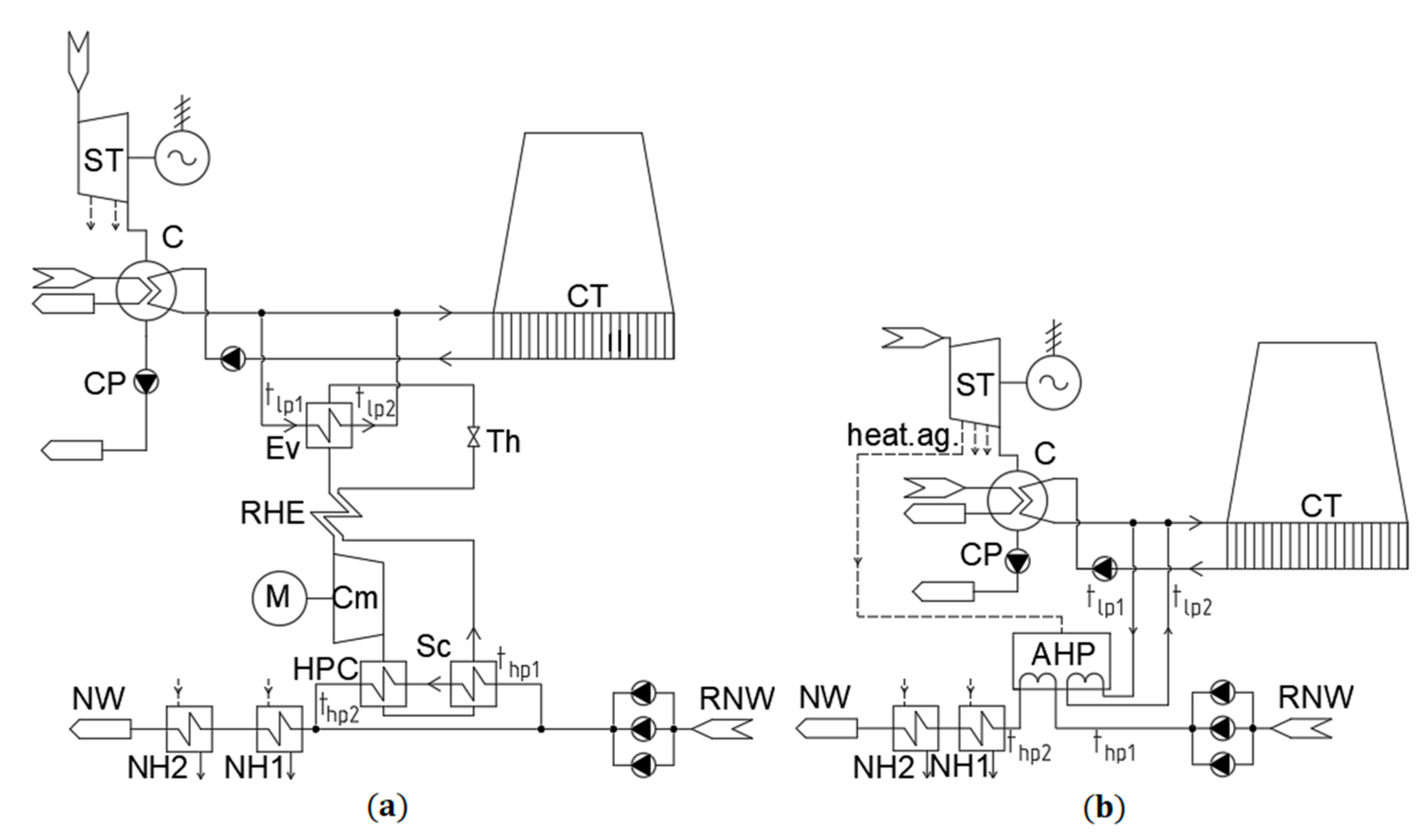
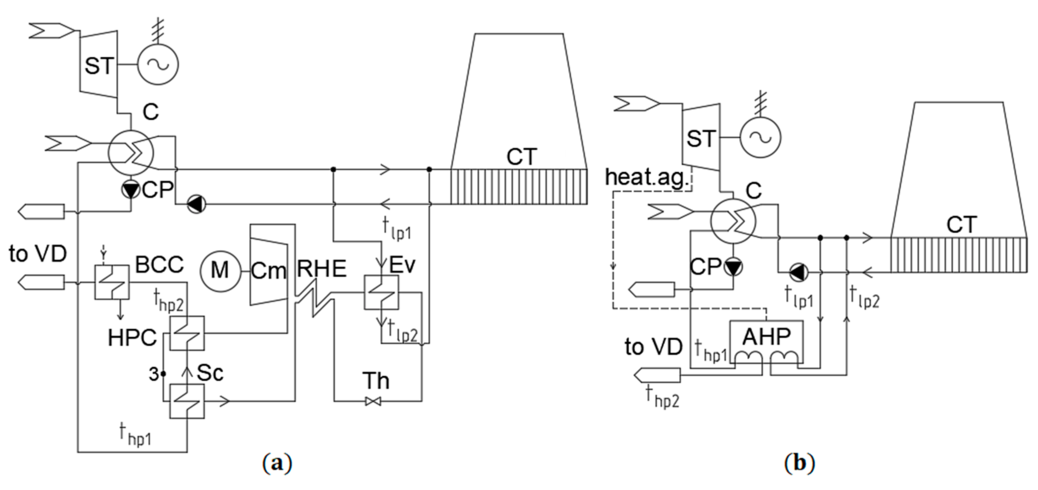
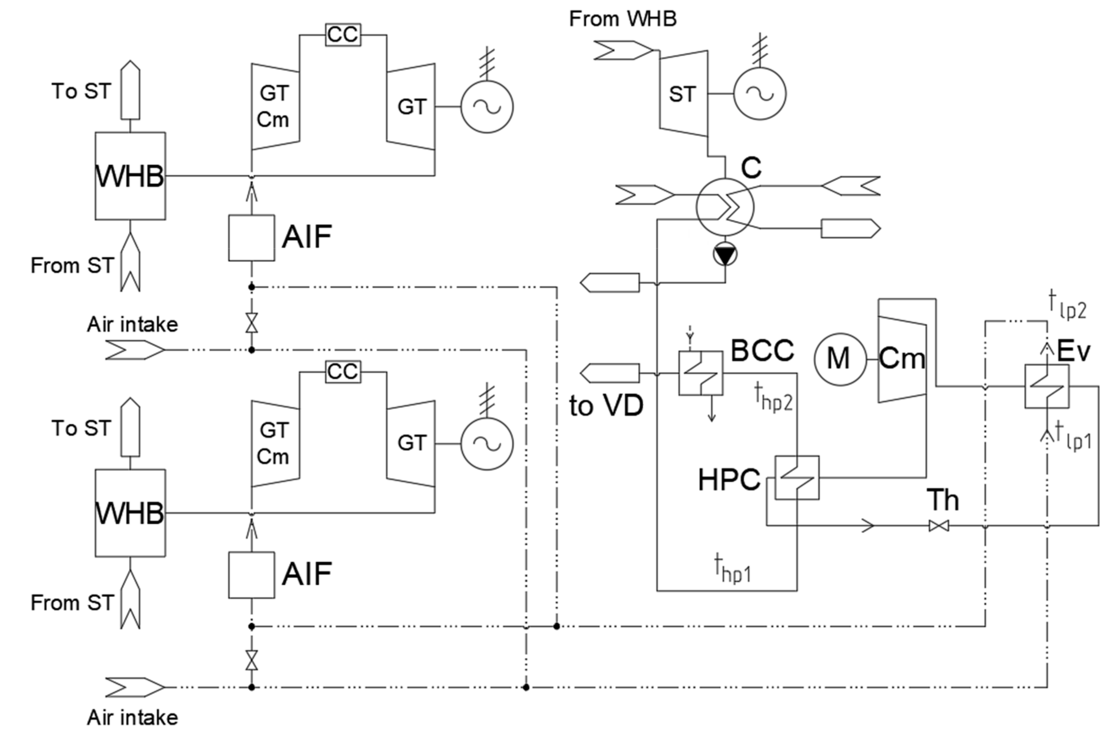
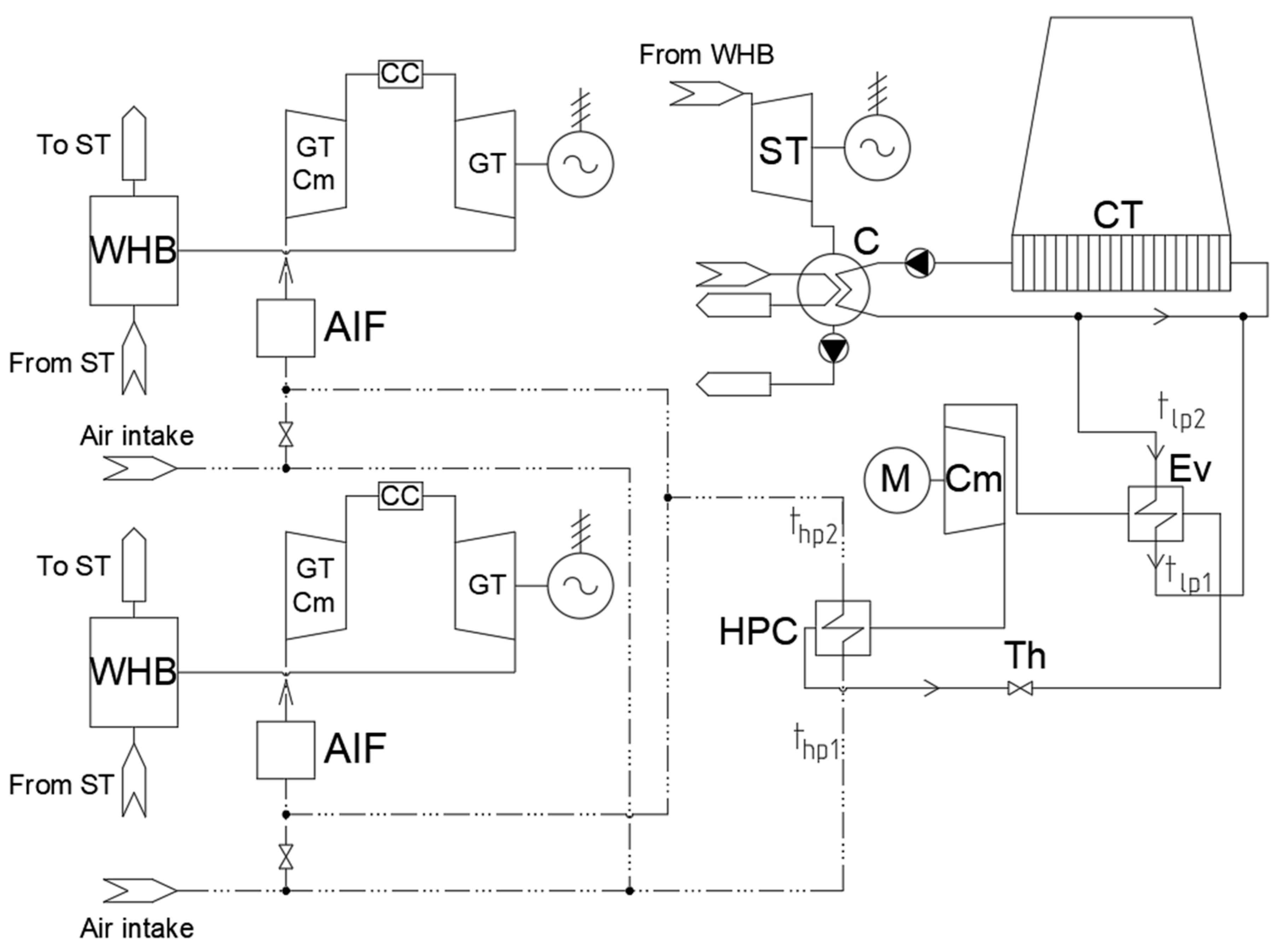
3.3. Schemes of HPUs Integration into a Combined-Cycle Gas Turbine Combined Heat and Power Plant (CCGT-CHPP)
- For heating return network water—a HPU installed before the unit mixing RNW with make-up water after the vacuum deaerator. The cooling water of the condenser acts as a LPHS (Figure 5);
4. Results and Discussion
4.1. Simulation Results
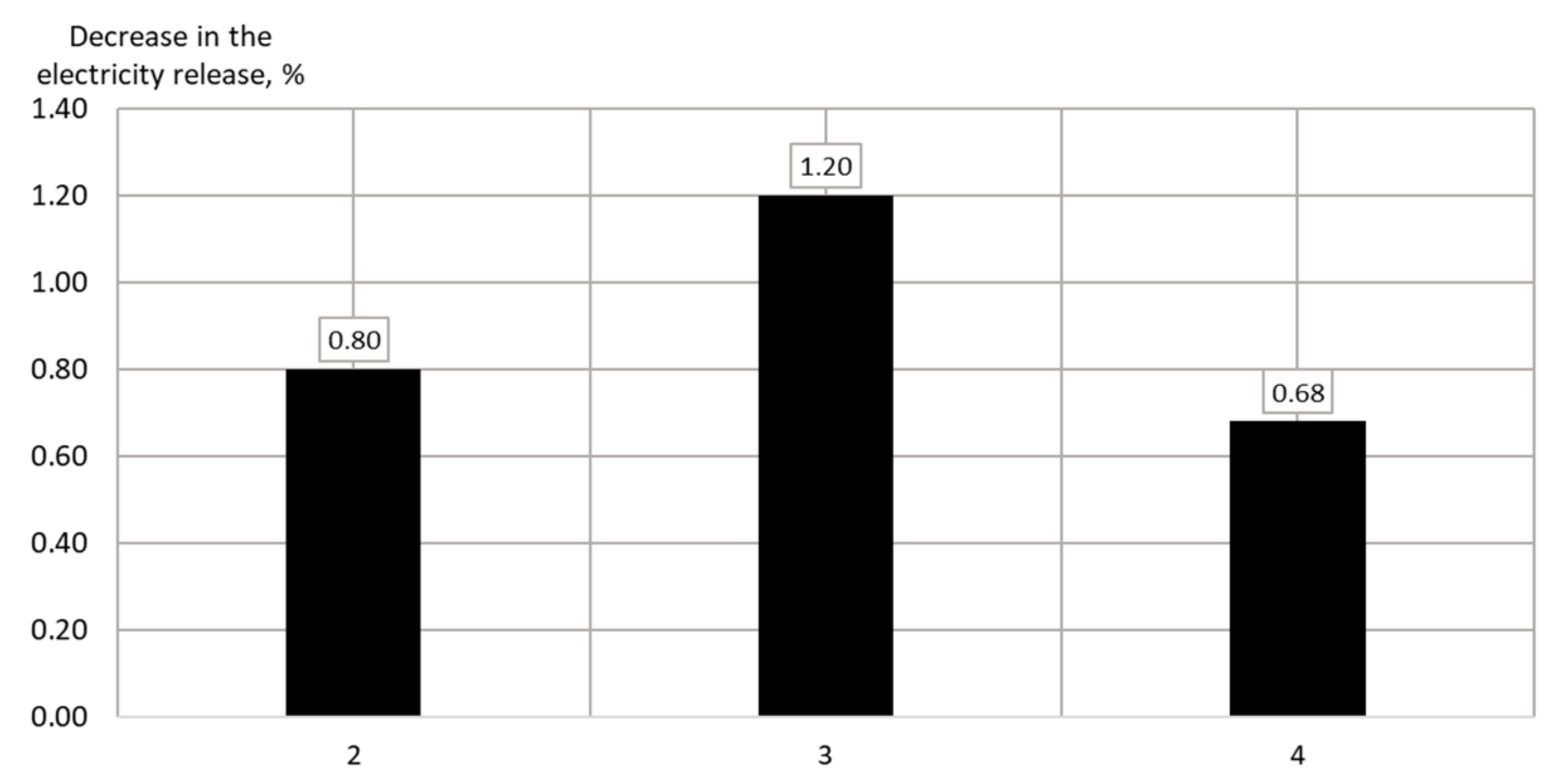
4.1.1. Use of HPUs for Heating Return Network Water
4.1.2. Use of HPUs for Heating Make-Up Water with a Flow Rate of 800 t/h
4.1.3. Use of HPUs for Heating Make-Up Water with a Flow Rate of 1500 t/h
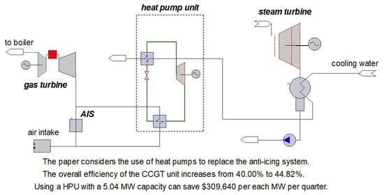
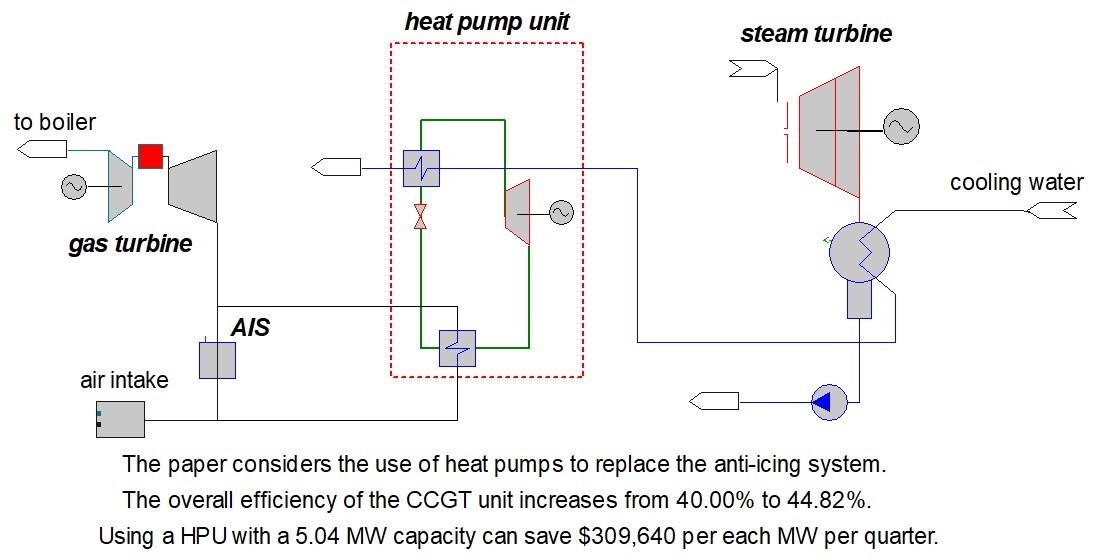
4.1.4. Use of HPUs for Heating the Intake Air
4.1.5. Use of HPUs for Cooling the Intake Air
4.2. Technical and Economic Indicators
4.2.1. Use of HPUs for Heating Make-Up Water with a Flow Rate of 1500 t/h
4.2.2. Use of HPUs for Heating the Intake Air
4.2.3. Use of HPUs for Cooling the Intake Air
5. Conclusions
- Different solutions for integrating the HPUs in a combined-cycle gas turbine (CCGT) plant, the CCGT-450, are analyzed based on simulations developed on “United Cycle” computer-aided design (CAD) system.
- Based on the results of the selection of low-potential heat sources and consumers, circuit solutions for the integration of HPUs were proposed:
- -
- the use a HPU to heat the GT intake air and replace anti-icing system, over the winter at high humidity conditions;
- -
- the use of heat pumps for air cooling at the intake of a gas turbine unit in the summer period of operation;
- -
- the use of heat pumps for heating water of a heating unit (return network or make-up water).
- The best solution was obtained for the winter operation mode replacing the ant-icing system by a HPU. This allows us to reduce the underproduction of electricity, associated with the losses because of the anti-icing system, up to 14.87%, when heating the inlet air from −2 °C to 8 °C. The overall efficiency of the CCGT unit increases from 40.00% to 44.82%. Using a HPU with a 5.04 MW capacity can save $309,640 per each MW per quarter.
Author Contributions
Funding
Institutional Review Board Statement
Informed Consent Statement
Data Availability Statement
Conflicts of Interest
Nomenclature
| Abbreviation | |
| AHP | absorption heat pump |
| AIF | air intake filter |
| AIS | anti-icing system |
| BCC | boiler condensate cooler |
| C | steam turbine condenser |
| CC | combustion chamber |
| CCGT | combined cycle gas turbine |
| CFHU | coefficient of fuel heat utilization |
| CHPP | combined heat and power plant |
| Cm | compressor |
| CP | condensate pump CAD; |
| CT | cooling tower of the circulating water supply system |
| heat.ag. | the heating agent of a AHP generator (extracted steam from a ST) |
| CTW | chemically treated water |
| Ev | evaporator |
| GT | gas turbine |
| GT Cm | gas turbine compressor |
| HPC | vapor-compression heat pump condenser |
| HPC ST | high-pressure turbine cylinder |
| HPD | high pressure drum |
| HPU | heat pump unit |
| LPC ST | low-pressure turbine cylinder |
| LPD | low-pressure drum |
| LPHS | low-potential heat source |
| MW | make-up water NH |
| NH | network heater |
| NP | network pump |
| NW | network water |
| RHE | regenerative heat exchanger |
| RNW | return network water |
| Sc | supercooler |
| ST | steam turbine |
| Th | throttle |
| UC | “United Cycle” |
| VCHP | vapor-compression heat pump unit |
| VD | vacuum deaerator |
| WHB | waste heat boiler |
| WWHE | water-to-water heat exchanger |
| Variables and Coefficients | |
| be | specific consumption of the reference fuel for electricity release with a HPU, t r.f./(MW∙h) |
| BfuelN | the reference fuel consumption for power generation, t r.f./h |
| N | power generation, MW |
| Neown | the electricity consumption for own needs, MW |
| NeHPU | electricity costs for a heat pump, determined primarily by the costs of the compressor drive (for modes with VCHP), MW |
| bheat | specific consumption of the reference fuel for heat release with a HPU, t r.f./(MW∙h) |
| Bfuelheat | the reference fuel consumption for heat generation, t r.f./h |
| Qheat | the total heat release, MW |
| QHPU | heat release from a HPU, MW |
| QstAHP | heat consumption from the steam extraction to an AHP generator, MW |
| Ne | the electricity release from ST and GTs generators, MW |
| Qfuel | the heat from gas burned in combustion chambers of GTs, MW |
| Bfuel | the reference fuel consumption, t r.f./h |
| 7 Gcal/t r.f. | the reference fuel combustion value |
| 1.163 | the coefficient for converting Gcal/h to MW: 1.163 MW = 1 Gcal/h |
| NeST | steam turbine power generation, MW |
| NeGT | gas turbine power generation, MW |
| Qbbcond | heat release in make-up water from the built-in tube bundle of the steam turbine, MW |
| QNH1 and QNH2 | heat release from network heaters, MW |
| QWWHE1 and QWWHE2 | heat release from water-to-water heat exchangers, MW |
| QBCC | heat release from boiler condensate cooler, MW |
| K | coefficient for converting the natural gas mass flow rate to the reference fuel consumption, — |
| Ggas | gas mass flow rate into the combustion chamber of one gas turbine, t/h |
| ρgas | gas density, kg/nm3 |
| Ke.CCGT | the split ration of fuel costs for the electricity release, — |
| QNCV = 35.88 MJ/m3 | net calorific value of the gas, MJ/m3 |
| ηCCGT | efficiency of CCGT, - |
| EE | economic effect (simplified margin income), $ |
| ΔQH | increment of heat as a result of the introduction of HPU, MW |
| CT | tariff cost of thermal energy for vacation, $/MW |
| ΔEH | increase in electricity costs for own needs after the integration of HPUs, MW |
| CON | tariff value of electric energy for own needs, $/(MW·h) |
| ΔNe | increment in the electricity release, MW |
| Ce | tariff cost of electricity for the electricity release, $/(MW·h) |
| tlp1, tlp2 | temperature of LPHS before and after VCHP |
| thp1, thp2 | temperature of a consumer before and after VCHP |
References
- Aminov, Z.; Nakagoshi, N.; Xuan, T.D.; Higashi, O.; Alikulov, K. Evaluation of the energy efficiency of combined cycle gas turbine. Case study of Tashkent thermal power plant, Uzbekistan. Appl. Therm. Eng. 2016, 103, 501–509. [Google Scholar] [CrossRef]
- Treshcheva, M.; Anikina, I.; Sergeev, V.; Skulkin, S.; Treshchev, D. Selection of Heat Pump Capacity Used at Thermal Power Plants under Electricity Market Operating Conditions. Energies 2021, 14, 226. [Google Scholar] [CrossRef]
- Godoy, E.; Scenna, N.J.; Benz, S.J. Families of optimal thermodynamic solutions for combined cycle gas turbine (CCGT) power plants. Appl. Therm. Eng. 2010, 30, 569–576. [Google Scholar] [CrossRef]
- Pihl, E.; Heyne, S.; Thunman, H.; Johnsson, F. Highly efficient electricity generation from biomass by integration and hybridization with combined cycle gas turbine (CCGT) plants for natural gas. Energy 2010, 35, 4042–4052. [Google Scholar] [CrossRef]
- Leo, T.L.; Perez-Grande, I.; Perez-del-Notario, P. Gas turbine turbocharged by a steam turbine: A gas turbine solution increasing combined power plant efficiency and power. Appl. Therm. Eng. 2003, 23, 1913–1929. [Google Scholar] [CrossRef]
- Ponce Arrieta, F.R.; Silva Lora, E.E. Influence of ambient temperature on combined-cycle power-plant performance. Appl. Therm. Eng. 2005, 80, 261–272. [Google Scholar] [CrossRef]
- Colmenar-Santos, A.; Gomez-Camazon, D.; Rosales-Asensio, E.; Blanes-Peiro, J.-J. Technological improvements in energetic efficiency and sustainability in existing combined-cycle gas turbine (CCGT) power plants. Appl. Energy 2018, 223, 30–51. [Google Scholar] [CrossRef]
- Olivenza-Leon, D.; Medina, A.; Calvo Hernandez, A. Thermodynamic modeling of a hybrid solar gas-turbine power plant. Energy Convers. Manag. 2015, 93, 435–447. [Google Scholar] [CrossRef]
- Mendeleev, D.I.; Galitskii, Y.Y.; Marin, G.E.; Akhmetshin, A.R. Study of the work and efWficiency improvement of combined-cycle gas turbine plants. In Proceedings of the International Scientific and Technical Conference Smart Energy Systems 2019 (SES-2019), Kazan, Russia, 18–20 September 2019; Volume 124, p. 05061. [Google Scholar] [CrossRef]
- Mendeleev, D.I.; Maryin, G.E.; Akhmetshin, A.R. Improving the efficiency of combined-cycle plant by cooling incoming air using absorption refrigerating machine. In Proceeding of the International Scientific Electric Power Conference, Saint Petersburg, Russia, 23–24 May 2019; Volume 643, p. 012099. [Google Scholar] [CrossRef]
- Anikina, I.D.; Sergeyev, V.V.; Amosov, N.T.; Luchko, M.G. Heat pumps application in flow-sheet of heat generation at thermal power plants. Int. Sc. J. Altern. Energy Ecol. 2016, 3–4, 39–49. [Google Scholar] [CrossRef]
- Anikina, I.D.; Sergeyev, V.V. Heat pumps’ application for energy efficiency rising of steam-power HPP. St. Petersburg St. Polytec. Un. J. 2013, 3, 56–61. [Google Scholar]
- Alimgazin, A.S.; Alimgazina, S.G.; Zhumagulov, M.G. Heat pump in a new modular configuration to recover low-grade heat emissions at enterprises. In Proceedings of the High Speed Turbomachines and Electrical Drives Conference 2020 (HSTED-2020), Prague, Czech Republic, 14–15 May 2020; Volume 178, p. 01003. [Google Scholar] [CrossRef]
- Alimgazin, A.S.; Prishchepova, S.A.; Sultanguzin, I.A. The use of heat transformers for the low-temperature secondary energy resources recovery in non-ferrous metallurgy enterprises. In Proceedings of the High Speed Turbomachines and Electrical Drives Conference 2020 (HSTED-2020), Prague, Czech Republic, 14–15 May 2020; Volume 178, p. 01017. [Google Scholar] [CrossRef]
- Zhang, H.S.; Zhao, H.B.; Li, Z.L. Performance analysis of the coal-fired power plant with combined heat and power (CHP) based on absorption heat pumps. J. Energy Inst. 2016, 89, 70–80. [Google Scholar] [CrossRef]
- Zhang, H.S.; Zhao, H.B.; Li, Z.L.; Hu, E. Optimization Potentials for the Waste Heat Recovery of a Gas-steam Combined Cycle Power Plant Based on Absorption Heat Pump. J. Therm. Sci. 2019, 28, 283–293. [Google Scholar] [CrossRef]
- Vannoni, A.; Giugno, A.; Sorce, A. Integration of a flue gas condensing heat pump within a combined cycle: Thermodynamic, environmental and market assessment. Appl. Therm. Eng. 2021, 184, 116276. [Google Scholar] [CrossRef]
- Russian Agency of Statistics. Resolution of June 23, 1999 N 46. The Approval of “Methodological Provisions for Calculating the Fuel and Energy Balance of the Russian Federation in Accordance with International Practice”; Russian Agency of Statistics: Moscow, Russia, 1999. [Google Scholar]
- Methodology of Calculating the Actual Indicators of the CCGT Unit for Filling in the Model 15506 in Addition to RD 34.08.552-95. TGC-1. Saint Petersburg, Russia. 2012. Available online: https://files.stroyinf.ru/Data2/1/4294816/4294816548.pdf (accessed on 10 September 2020).
- Anikina, I.D. Heat pumps application for increasing the efficiency of the cogeneration at thermal power plants. In Proceedings of the Efficient Energetics—2015, St. Petersburg, Russia, 21–22 May 2015; pp. 7–13. [Google Scholar]
- Gorshkov, V.G. Teplovyye nasosy. Analiticheskiy obzor [Heat pumps. Analytical review]. Spravochnik Promyshlennogo Oborudovaniya 2004, 2, 47–80. Available online: http://allbeton.ru/upload/iblock/10e/teplovie-nasosi-analiticheskiy-obzor-qgorshkovt.pdf (accessed on 15 November 2020).
- Sergeyev, V.V.; Anikina, I.D.; Kalmykov, K.S.; Naletov, I.D. Efficiency of using heat pumps with various refrigerants in real steam turbine power units with PT-80 and T-250 turbines. In Proceedings of the International Scientific Conference on Energy, Environmental and Construction Engineering (EECE-2019), Saint-Petersburg, Russia, 19–20 November 2019; Volume 140, p. 10001. [Google Scholar] [CrossRef]
- Jakobsen, A.; Rasmussen, B.D.; Andersen, S.E. CoolPack—Simulation tools for refrigeration systems. Scan. Ref. 1999, 28, 7–10. [Google Scholar]
- Popov, A.V. Lithium bromide absorption machines for water cooling and heating. Energy Sav. 2007, 7, 52–55. [Google Scholar]
- Romanov, S.; Kutakhov, A.; Zhuk, N.; Demidov, O.; Romanov, K. “United Cycle” Software for Simulation of Flow Sheets of Power Plants. In Proceeding of the 16th International Conference on Efficiency, Cost, Optimization, Simulation, and Environmental Impact of Energy Systems (ECOS-2003), Copenhagen, Denmark, 30 June–2 July 2003; pp. 1691–1696. [Google Scholar]
- Demidov, O.; Kutakhov, A.; Romanov, S. Simulation of AVV1 St Power Plant with United Cycle Software. In Proceeding of the 16th International Conference on Efficiency, Cost, Optimization, Simulation, and Environmental Impact of Energy Systems (ECOS-2003), Copenhagen, Denmark, 30 June–2 July 2003; pp. 1697–1704. [Google Scholar]
- Demidov, O.I.; Zhuk, N.I.; Ivanov, V.A.; Koren, V.M.; Kutakhov, A.G.; Romanov, S.N. CAD “Teplovaya schema”: Complex automation of development, calculation and optimization of thermal schemes of power units on TPP and NPP. Proc. Power Mach. Plants 1999, 481, 115–123. [Google Scholar]
- Branch of “Power Machines—ZTL, LMZ, Elektrosila, Energomashexport” “Leningrad Metal Plant” in St. Petersburg, Operation Manual 3170107. “Leningrad Metal Plant”; TGC-1: Saint Petersburg, Russia, 2008.
- Anikina, I.D. Influence of heat pumps inclusion in deaeration scheme of heating network make-up water on the operating modes of the TPP. In Proceedings of the International Scientific Conference on Energy, Environmental and Construction Engineering EECE-2018, Saint-Petersburg, Russia, 19–20 November 2018; Volume 245, p. 15004. [Google Scholar] [CrossRef]
- Operating Instructions for the Integrated Air Intake Filter (AIF) for the Gas Turbine GTU-160 of the POWER Unit 4; TGC-1: Saint Petersburg, Russia, 2016.
- Treshcheva, M.; Treshchev, D.; Anikina, I.; Skulkin, S. The potential for reducing TPP water consumption through the use of heat pumps. In Proceedings of the International Scientific Conference on Energy, Environmental and Construction Engineering (EECE-2019), Saint-Petersburg, Russia, 19–20 November 2019; Volume 140, p. 11001. [Google Scholar] [CrossRef]


| Parameter | Value | |
|---|---|---|
| Absorption Heat Pump (AHP) Type | AHP-P | AHP2-P |
| Heating capacity, kW | 850–10,000 | 600–7200 |
| Temperature of cooled water, °C | 30/25 | 30/25 |
| Temperature of heated water, °C | 30/80 | 30/55 |
| Heating agent | Steam | |
| Heating steam pressure, MPa | 0.4 | 0.7 |
| Transformation ratio, - | 1.75 | 2.25 |
| Parameter | Model Data | Control Data | Deviation, % |
|---|---|---|---|
| Power at the terminals of the gas turbine (GT) generator, MW | 155.3 | 155.3 | 0.00 |
| Gas turbine exhausted gas temperature, °C | 537 | 537 | 0.00 |
| Gas turbine exhausted gas mass flow rate, kg/s | 509 | 509 | 0.00 |
| High-pressure steam mass flow rate, t/h | 231.2 | 234.6 | 1.45 |
| High-pressure steam temperature, °C | 506.5 | 512.84 | 1.24 |
| High-pressure steam pressure, 10−1 MPa | 38.61 | 38.61 | 0.00 |
| Low-pressure steam mass flow rate, t/h | 39.0 | 40.4 | 3.47 |
| Low-pressure steam temperature, °C | 209.6 | 207.95 | 0.79 |
| Low-pressure steam pressure, 10−1 MPa | 4.1 | 4.1 | 0.00 |
| Power at the terminals of the steam turbine (ST) generator, MW | 58.94 | 61.52 | 4.19 |
| Steam mass flow rate in the condenser, t/h | 161.64 | 165.13 | 2.11 |
| Pressure in the condenser, 10−1 MPa | 0.033 | 0.034 | 2.94 |
| Steam pressure in network heater NH-1, 10−1 MPa | 0.856 | 0.863 | 0.81 |
| Steam mass flow rate to NH-1, t/h | 106.38 | 107.62 | 1.15 |
| Heat load of NH-1, MW | 67.64 | 68.34 | 1.02 |
| Return network water (RNW) temperature, °C | 89.8 | 90.0 | 0.22 |
| RNW mass flow rate, t/h | 2933 | 2933 | 0.00 |
| Feed water mass flow rate at the intake of WHB, t/h | 270.2 | 275.0 | 1.75 |
| LPHSs of Cooling Systems | LPHSs of Waste Systems |
|---|---|
| Equipment oil cooling system | Purging the water recycling system |
| Condenser cooling system | Waste gases |
| Turbine oil cooling system | Purging drums |
| Equipment air cooling system | Sewer drains |
| Positive Aspects | Negative Aspects |
|---|---|
| High heat-transfer coefficient | Dependence on the operating mode of the main equipment of a CHPP |
| Low costs for intake and transport of a heat carrier in the case of heating make-up or RNW | Direct relationship with the ST mode |
| Rather high evaporation temperature of a HPU working fluid | Complexity of a HPU load regulation to maintain standard operating modes |
| Large range of variation of the heat carrier flow | |
| Reducing the cost of driving circulating water pumps |
| Positive Aspects | Negative Aspects |
|---|---|
| High heat transfer coefficient | Dependence on the operating mode of the gas turbine |
| Rather high evaporation temperature of a HPU working fluid | Complexity of a HPU regulation to maintain the air temperature level |
| Reduced GT compressor drive costs | Small range of variation of the heat carrier flow |
| Increasing the capacity of the GT (Figure 3) |
| Parameter | Value | ||||||
|---|---|---|---|---|---|---|---|
| HPU Type and Power | Initial Mode | VCHP with a RHE and a Sc, 20 MW | AHP2-P, 20 MW | AHP-P, 20 MW | VCHP with a RH and a Sc, 40 MW | AHP2-P, 40 MW | AHP-P, 40 MW |
| Mode number | 1 | 2 | 3 | 4 | 5 | 6 | 7 |
| RNW temp. before/after HPU, °C | 61.1/61.1 | 61.1/64.1 | 61.1/64.1 | 61.1/64.1 | 61.1/67.0 | 61.1/67.0 | 61.1/67.0 |
| Energy conv. coef. (transform. ratio), - | - | 3.70 | 2.25 | 1.75 | 3.54 | 2.25 | 1.75 |
| LPHS mass flow rate, t/h | - | 1674.42 | 1405.85 | 1117.38 | 2743.36 | 2515.91 | 2048.62 |
| Tot. own needs, MW | 8.94 | 16.96 | 9.48 | 9.48 | 25.07 | 9.58 | 9.55 |
| Heat release, MW | 312.15 | 312.15 | 312.15 | 312.27 | 312.27 | 312.38 | 312.38 |
| Elec. release, MW | 432.62 | 427.01 | 428.93 | 431.11 | 421.30 | 425.95 | 430.39 |
| Parameter | Value | |||
|---|---|---|---|---|
| HPU Type and Power | Initial Mode | VCHP with a RHE and a Sc, 20 MW | AHP2-P, 20 MW | AHP-P, 20 MW |
| Mode number | 1 | 2 | 3 | 4 |
| Make-up wat. temp. before/after HPU, °C | 21.5/21.5 | 21.5/43.0 | 21.5/43.0 | 21.5/43.0 |
| Energy conv. coef. (transform. ratio), - | - | 7.39 | 2.25 | 1.75 |
| LPHS mass flow rate, t/h | - | 2439.09 | 1770.16 | 1418.04 |
| Tot. own needs, MW | 8.94 | 12.88 | 9.14 | 9.11 |
| Heat release, MW | 312.15 | 312.27 | 312.38 | 312.27 |
| Elec. release, MW | 432.62 | 429.16 | 427.45 | 429.67 |
| Parameter | Value | ||||||
|---|---|---|---|---|---|---|---|
| HPU Type and Power | Initial Mode | VCHP with a RHE and a Sc, 20 MW | AHP-P 20 MW | VCHP with a RHE and a Sc, 25 MW | VCHP with a RHE and a Sc, 30 MW | VCHP with a RHE and a Sc, 35 MW | VCHP with a RHE and a Sc, 40 MW |
| Mode number | 1 | 2 | 3 | 4 | 5 | 6 | 7 |
| Make-up wat. temp. before/ after HPU, °C | 13.5/13.5 | 13.5/42.2 | 13.5/42.2 | 13.5/49.4 | 13.5/56.6 | 13.5/63.8 | 13.5/70.9 |
| Energy conv. coef. (transform. ratio), - | - | 7.89 | 1.75 | 6.60 | 5.70 | 5.01 | 4.48 |
| LPHS mass flow rate, t/h | - | 4418.24 | 1675.74 | 5366.18 | 6446.54 | 7530.69 | 8354.19 |
| Tot. own needs, MW | 8.88 | 12.81 | 9.14 | 14.6 | 16.71 | 19.14 | 21.85 |
| Heat release, MW | 373.13 | 381.23 | 361.09 | 382.38 | 383.55 | 384.50 | 385.20 |
| Elec. release, MW | 428.49 | 424.55 | 428.23 | 422.77 | 420.67 | 418.24 | 415.54 |
| GT efficiency, % | 33.29 | 33.29 | 33.29 | 33.29 | 33.29 | 33.29 | 33.29 |
| CCGT efficiency, % | 44.47 | 44.06 | 44.44 | 43.88 | 43.66 | 43.41 | 43.13 |
| Parameter | Value | |||||
|---|---|---|---|---|---|---|
| Air Heating Device | AIS | VCHP sim.sch., 3.05 MW | AIS | VCHP sim.sch., 4.05 MW | AIS | VCHP sim.sch., 5.04 MW |
| Mode number | 1 | 2 | 3 | 4 | 5 | 6 |
| Outside air temperature, °C | −2 | −2 | −2 | −2 | −2 | −2 |
| Air temperature after heating, °C | +4 | +4 | +6 | +6 | +8 | +8 |
| Total air mass flow rate, t/h | 1788.67 | 1821.58 | 1767.91 | 1811.52 | 1747.28 | 1801.45 |
| Air mass flow rate through HPU, t/h | - | 223.96 | - | 297.12 | - | 369.55 |
| Required heat release from HPU, MW | - | 3.05 | - | 4.05 | - | 5.04 |
| Energy conv. coef., - | - | 6.04 | - | 6.04 | - | 6.04 |
| LPHS mass flow rate, t/h | - | 413.67 | - | 559.36 | - | 709.37 |
| Tot. own needs, MW | 8.65 | 10.31 | 8.61 | 10.76 | 8.56 | 11.20 |
| Heat release, MW | 312.01 | 312.00 | 311.97 | 311.95 | 311.96 | 311.93 |
| Elec. release by GT, MW | 139.56 | 155.15 | 132.90 | 153.46 | 126.36 | 151.78 |
| Elec. release, MW | 384.45 | 416.84 | 369.77 | 412.61 | 355.54 | 408.40 |
| Increment of electricity release, % | - | 8.43 | - | 11.59 | - | 14.87 |
| GT efficiency, % | 30.42 | 33.35 | 29.43 | 33.34 | 28.43 | 33.32 |
| CCGT efficiency, % | 41.89 | 44.80 | 40.94 | 44.82 | 40.00 | 44.82 |
| CFHU, % | 80.51 | 83.09 | 80.08 | 83.49 | 79.66 | 83.87 |
| Parameter | Value | |||
|---|---|---|---|---|
| HPU Type and Power | Initial Mode | VCHP sim.sch., 12.45 MW | VCHP with a RHE, 12.45 MW | VCHP with a RHE and a Sc, 12.26 MW |
| Mode number | 1 | 2 | 3 | 4 |
| Outside air temperature, °C | +15 | +15 | +15 | +15 |
| Air temperature after heating, °C | +15 | +5 | +5 | +5 |
| Total air mass flow rate, t/h | 1760.82 | 1816.56 | 1816.56 | 1816.56 |
| Air mass flow rate through HPU, t/h | - | 1816.56 | 1816.56 | 1816.56 |
| Required evaporator capacity, MW | - | 10.19 | 10.19 | 10.19 |
| Energy conv. coef., - | - | 5.52 | 5.54 | 6.04 |
| Tot. own needs, MW | 8.80 | 15.18 | 15.16 | 14.57 |
| Heat release, MW | 256.86 | 256.73 | 256.73 | 256.73 |
| Elec. release, MW | 405.16 | 418.44 | 418.46 | 419.05 |
| Increment of electricity release, % | - | 3.28 | 3.28 | 3.43 |
| GT efficiency, % | 33.23 | 33.35 | 33.35 | 33.35 |
| CCGT efficiency, % | 46.15 | 45.22 | 45.22 | 45.29 |
| CFHU, % | 79.99 | 77.41 | 77.41 | 77.47 |
| Parameter | Value | |||||
|---|---|---|---|---|---|---|
| HPU Type and Power | Initial Mode | VCHP with a RHE and a Sc, 20 MW | VCHP with a RHE and a Sc, 25 MW | VCHP with a RHE and a Sc, 30 MW | VCHP with a RHE and a Sc, 35 MW | VCHP with a RHE and a Sc, 40 MW |
| Mode number | 1 | 2 | 4 | 5 | 6 | 7 |
| The method with a fixed specific fuel consumption for the heat release | ||||||
| Consumption of ref. fuel for electricity release, t r.f./h | 62.15 | 61.08 | 60.92 | 60.77 | 60.64 | 60.55 |
| Consumption of ref. fuel for heat release, t r.f./h | 49.41 | 50.48 | 50.63 | 50.79 | 50.91 | 51.01 |
| Specific consumption of ref. fuel for electricity release, g. r.f./(kW∙h) | 145.05 | 143.86 | 144.11 | 144.46 | 145.00 | 145.72 |
| Specific consumption of ref. fuel for heat release, kg. r.f./MW | 132.42 | |||||
| “Model 15506” | ||||||
| Consumption of ref. fuel for electricity release, t r.f./h | 71.72 | |||||
| Consumption of ref. fuel for heat release, t r.f./h | 39.84 | |||||
| Specific consumption of ref. fuel for electricity release, g. r.f./(kW∙h) | 167.37 | 168.92 | 169.63 | 170.48 | 171.47 | 172.59 |
| Specific consumption of ref. fuel for heat release, kg. r.f./MW | 106.78 | 104.51 | 104.20 | 103.88 | 103.62 | 103.43 |
| Parameter | Value | |||||
|---|---|---|---|---|---|---|
| Air Heating Device | AIS | VCHP sim.sch., 3.05 MW | AIS | VCHP sim.sch., 4.05 MW | AIS | VCHP sim.sch., 5.04 MW |
| Mode number | 1 | 2 | 3 | 4 | 5 | 6 |
| Air temperature after heating, °C | +4 | +4 | +6 | +6 | +8 | +8 |
| Economic effect, 103 $/(MW∙quarter) | - | 313.08 | - | 312.21 | - | 309.64 |
| The method with a fixed specific fuel consumption for the heat release | ||||||
| Consumption of ref. fuel for electricity release, t r.f./h | 64.94 | 66.42 | 63.26 | 65.28 | 61.61 | 64.19 |
| Consumption of ref. fuel for heat release, t r.f./h | 41.31 | 41.31 | 41.31 | 41.31 | 41.31 | 41.30 |
| Specific consumption of ref. fuel for electricity release, g. r.f./(kW∙h) | 168.91 | 159.34 | 171.08 | 158.22 | 173.28 | 157.18 |
| Specific consumption of ref. fuel for heat release, kg. r.f./MW | 132.42 | |||||
| “Model 15506” | ||||||
| Consumption of ref. fuel for electricity release, t r.f./h | 68.30 | 69.26 | 67.22 | 68.52 | 66.16 | 67.82 |
| Consumption of ref. fuel for heat release, t r.f./h | 37.95 | 38.48 | 37.35 | 38.07 | 36.76 | 37.68 |
| Specific consumption of ref. fuel for electricity release, g. r.f./(kW∙h) | 177.67 | 166.15 | 181.80 | 166.07 | 186.08 | 166.06 |
| Specific consumption of ref. fuel for heat release, kg. r.f./MW | 121.63 | 123.32 | 119.71 | 122.03 | 117.82 | 120.78 |
| Parameter | Value | |||
|---|---|---|---|---|
| HPU Type and Power | Initial Mode | VCHP sim.sch., 12.45 MW | VCHP with a RHE, 12.45 MW | VCHP with a RHE and a Sc, 12.26 MW |
| Mode number | 1 | 2 | 3 | 4 |
| Economic effect, 103 $/(MW∙quarter) | - | 16.83 | 16.93 | 20.23 |
| The method with a fixed specific fuel consumption for the heat release | ||||
| Consumption of ref. fuel for electricity release, t r.f./h | 67.64 | 73.14 | 73.14 | 73.14 |
| Consumption of ref. fuel for heat release, t r.f./h | 34.01 | 34.00 | 34.00 | 34.00 |
| Specific consumption of ref. fuel for electricity release, g. r.f./(kW∙h) | 166.95 | 174.79 | 174.78 | 174.54 |
| Specific consumption of ref. fuel on heat release, kg. r.f./MW | 132.42 | |||
| “Model 15506” | ||||
| Consumption of ref. fuel for electricity release, t r.f./h | 65.35 | 68.87 | 68.87 | 68.87 |
| Consumption of ref. fuel for heat release, t r.f./h | 36.30 | 38.26 | 38.26 | 38.26 |
| Specific consumption of ref. fuel for electricity release, g. r.f./(kW∙h) | 161.29 | 164.60 | 164.59 | 164.36 |
| Specific consumption of ref. fuel for heat release, kg. r.f./MW | 141.34 | 149.04 | 149.04 | 149.04 |
Publisher’s Note: MDPI stays neutral with regard to jurisdictional claims in published maps and institutional affiliations. |
© 2021 by the authors. Licensee MDPI, Basel, Switzerland. This article is an open access article distributed under the terms and conditions of the Creative Commons Attribution (CC BY) license (https://creativecommons.org/licenses/by/4.0/).
Share and Cite
Sergeev, V.; Anikina, I.; Kalmykov, K. Using Heat Pumps to Improve the Efficiency of Combined-Cycle Gas Turbines. Energies 2021, 14, 2685. https://doi.org/10.3390/en14092685
Sergeev V, Anikina I, Kalmykov K. Using Heat Pumps to Improve the Efficiency of Combined-Cycle Gas Turbines. Energies. 2021; 14(9):2685. https://doi.org/10.3390/en14092685
Chicago/Turabian StyleSergeev, Vitaly, Irina Anikina, and Konstantin Kalmykov. 2021. "Using Heat Pumps to Improve the Efficiency of Combined-Cycle Gas Turbines" Energies 14, no. 9: 2685. https://doi.org/10.3390/en14092685
APA StyleSergeev, V., Anikina, I., & Kalmykov, K. (2021). Using Heat Pumps to Improve the Efficiency of Combined-Cycle Gas Turbines. Energies, 14(9), 2685. https://doi.org/10.3390/en14092685