Article

Evaluation of the Effect of Anti-Corrosion Coatings on the Thermal Resistance of Ground Heat Exchangers for Shallow Geothermal Applications

1
Institute of Atmospheric Sciences and Climate (CNR-ISAC), National Research Council of Italy, 35127 Padua, Italy
2
Institute of Construction Technologies (CNR-ITC), National Research Council of Italy, 35127 Padua, Italy
3
Department of Geosciences, University of Padua, 35131 Padua, Italy
*
Author to whom correspondence should be addressed.
Energies 2021, 14(9), 2586; https://doi.org/10.3390/en14092586
Submission received: 24 March 2021 / Revised: 22 April 2021 / Accepted: 27 April 2021 / Published: 30 April 2021
(This article belongs to the Special Issue Shallow Geothermal Energy 2021)

Abstract

:
The materials and the technology used to build the ground heat exchangers significantly affect the heat transfer performance of a geothermal system, in addition to the local geological and hydrogeological context. Among expense items such as the coupled heat pumps and the applied drilling technology, the heat exchangers play a key role in the shallow geothermal market. For this reason, they are usually made with plastic. Metal tubes are not widely used because of corrosion issues, which can compromise the reliability of the system over time. According to best practices, metal is an unfavorable choice if the pipes are not made of corrosion resistant alloys, such as stainless steel, but the overall performance is strongly related to the heat transfer efficiency. In this study, laser-flash technique is applied on carbon steel samples with anti-corrosion coatings and on corrosion resistant materials (stainless steel grades used for pipes), thus, allowing the comparison of their thermophysical properties. These properties are used to evaluate each solution in terms of thermal resistance. This study demonstrates that there are no particular corrosion resistant steel pipe configurations that are thermally favorable over others in a critical way.

Graphical Abstract

1. Introduction

Shallow geothermal systems have proved reliability in efficiently supplying heating and cooling to buildings. Ground heat exchangers (GHEs) are tubes inserted into the ground, where a fluid flows inside, allowing the heat exchange between the ground and the building. The heat transfer fluid can be only water, or water with anti-freezing and anti-algal additives. In winter, the heat is extracted from the subsoil and supplied to the building, which is vice-versa in the summer. The whole system is managed by a heat pump, granting the heat transfer between the GHE and the building. The heat exchange capacity of the system mainly depends on the local geological setting such as stratigraphy, hydrological conditions, and undisturbed ground temperature, and on the materials and technology used to build the GHEs [1,2].
Recently, an improved GHE installation method was proposed [3,4,5,6], which is an enhancement of the well-known piling technique. Such a method is specific for coaxial GHE and it implies the absence of grouting, so the outer pipe is in direct contact with the surrounding subsoil. In this way, the borehole resistance between the external metallic tube and the soil is significantly lower than that of standard, grouted, heat exchangers, thereby increasing the thermal performance of the coaxial GHE.
In addition, the characteristics of the properly designed drilling head and its operation significantly limit the abrasion with the subsoil. In fact, using this drilling technique, the external tube does not rotate during installation because the torque is transferred to the drill, but from an internal shaft, while the tube is mechanically decoupled by means of ball bearing elements while it is dragged into the ground. This is crucial because it opens the possibility to use thermoplastics and coated metals for the outer pipe, which cannot be easily used with other methodologies. In fact, thermoplastic materials, such as HDPE, cannot easily withstand the compression load during the piling operation. Moreover, galvanized metallic materials can suffer the risk of damaging the coating or the galvanized layer during the piling process [7,8]. With this newly developed drilling methodology, three kinds of materials can be more safely selected as the outer pipe in order to optimize cost, corrosion-safety, and thermal performance, which include HDPE, stainless steels, and coated carbon steel. The thermal performance of pipe or pipe-coating systems, represented here by thermal resistance values (as defined in Section 3.3), is a combination of the thermal properties of pipes and coatings, and their geometries (i.e., the thickness of each layer and the ratio of radii). It is well known that there are other factors that could affect the heat transfer between the fluid and the ground (e.g., the viscosity of the fluid, its laminar or turbulent flow, and the presence of fins or other elements [9,10], such as changes in the diameter or the presence of incrustations on the inside wall of the pipe). However, they have not been considered because they do not influence the goal of this study focused on assessing and comparing the effects of anti-corrosion measures applied on the outer wall only. In particular, a laboratory measurement of anti-corrosion coatings represented a core part of the work. The application of the experimental techniques used to obtain thermal conductivity, i.e., by measuring the thermal diffusivity in single-side configuration, has been proposed as a method, which could be worth considering for future research in the field of thin coatings for ground, geothermal, heat exchangers. While the general issues of characterizing the thermal properties of materials and modeling the thermal behavior of pipes have been discussed in the literature [11], this work proposes an alternative, clear, and reliable path to measure the properties of coated pipes, leading to an optimal choice and design of heat exchangers. The ultimate goal is to evaluate and compare the thermal performance of different solutions that are very specific for the new installation method. This is meant to provide indications that can allow for more precise design choices, which can, therefore, be based on other parameters, such as costs or geological/hydrogeological compatibility.
Table 1 shows that stainless steel costs over three times more than carbon steel. The latter costs about as much of HDPE plastic, but presents significantly better thermal properties.
Concerning durability and performance, if carbon steel GHEs are used, it is mandatory to implement anti-corrosive measures, such as coatings or a sacrificial anode. The environmental aspect is paramount. It is fundamental to avoid issues concerning leaks of the heat-transfer fluids flowing inside the pipes (e.g., glycol mixtures often with anticorrosive/antialgal additives). For coaxial GHEs in direct contact with the subsoil, the addition of a coating layer around the pipe might be a factor impacting on the thermal performance of the system. In order to evaluate different GHE solutions, a comparison in terms of thermophysical properties has been held. Six different solutions have been considered: (I) HDPE, (II) Stainless steel AISI 304, (III) Stainless steel AISI 316 (Marine grade stainless steel), (IV) Carbon steel S235JRH, (V) Carbon steel S235JRH with bitumen coating, and (VI) Carbon steel S235JRH with alkyd-based primer coating.
For each of them, we obtain the thermal properties of the material used for the pipe, the coatings, and, then, evaluate the total thermal resistance as the sum of the thermal resistance of both the pipe and the coating, if any. Finally, the different solutions have been compared.

2. Materials and Methods

2.1. Passive and Active Anti-Corrosion Measures for Buried Carbon Steel Pipes

Passive protection is used to mechanically insulate the metal surface from the external environment by means of a coating. The most common are:
  • protective films of proper paint applied over the entire length of the pipe or only in points subject to corrosion, such as polyethylene-based protective coatings as prescribed by UNI 9099 [12] (other coatings are applicable as a paint, i.e., primer), or bitumen according to UNI 5256 [13];
  • oxidation products obtained, e.g., by anodic oxidation of metals such as Al, Ni, or Co. The oxides of these materials are very tough and adherent to the surface layer, insulating them from the environment. Metals, such as Zn, could be applied by immersing the Fe-alloy in a galvanic bath of molten Zinc or attaching a bulk sacrificial anode made of Zinc alloy to the pipe in case of stray currents. With Zn being more reducing than Fe, oxidation proceeds on the Zn and the pipe remains protected until all the Zn has been consumed. Moreover, other metals such as Cr, could be applied by plating/cladding the pipes.
Other coverings with an insulating effect due to their materials and thickness, widely used in aerial pipelines [14], cannot be used for GHEs because they would critically limit the overall efficiency.
Conversely, active methods consisting of applying a reverse electromotive force, where the pipe is connected to the negative pole of a direct current generator whose positive pole is, in turn, connected to an inert electrode, would not add any additional thermal resistance to the GHE. This system is called Impressed Current Cathodic Protection (ICCP) and has a higher installation and maintenance cost than the previously mentioned methods. Therefore, it is quite inconvenient for cost-effective/long-term applications, such as GHEs. Another method is the use of a sacrificial anode, but it is not suitable in the case of piled GHEs because it protrudes with respect to the tube profile and this is not acceptable during drilling/installation procedures.
For the sake of this study, only bitumen and primer were considered. They were also found to be very relevant because such coatings are still used to protect the weld joints when the carbon steel pipe is galvanized or even plated.

2.2. Stainless-Steel Grades with Anti-Corrosive Action Used for Piping

Stainless steel is an alloy of Fe, Cr, and C. Occasionally, it has other complementary elements, such as Ni (the most common) and Mo. Cr is the element that provides the stainless characteristic of the material. In an oxidizing environment, Cr produces a very dense and thin oxide layer that allows us to isolate the material from any corrosive action as long as it is kept intact. Stainless steels are subdivided in martensitic, ferritic, and austenitic, according to the amount of the elements in their composition. Austenitic is the group with the greatest advantages in manufacturing, as well as in service performance, such as easy welding and great corrosion resistance. AISI 304 contains 18% Cr and 8% Ni, whereas AISI 316 contains 16% Cr, 10% Ni, and 2% Mo. The latter is added to enhance resistance to corrosion from chlorides (common in seawater and marine environments).
Being among the most common materials for structural pipes and underground structures, such stainless steel grades were selected in their category as representatives for the purpose of this study.

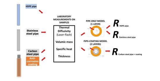
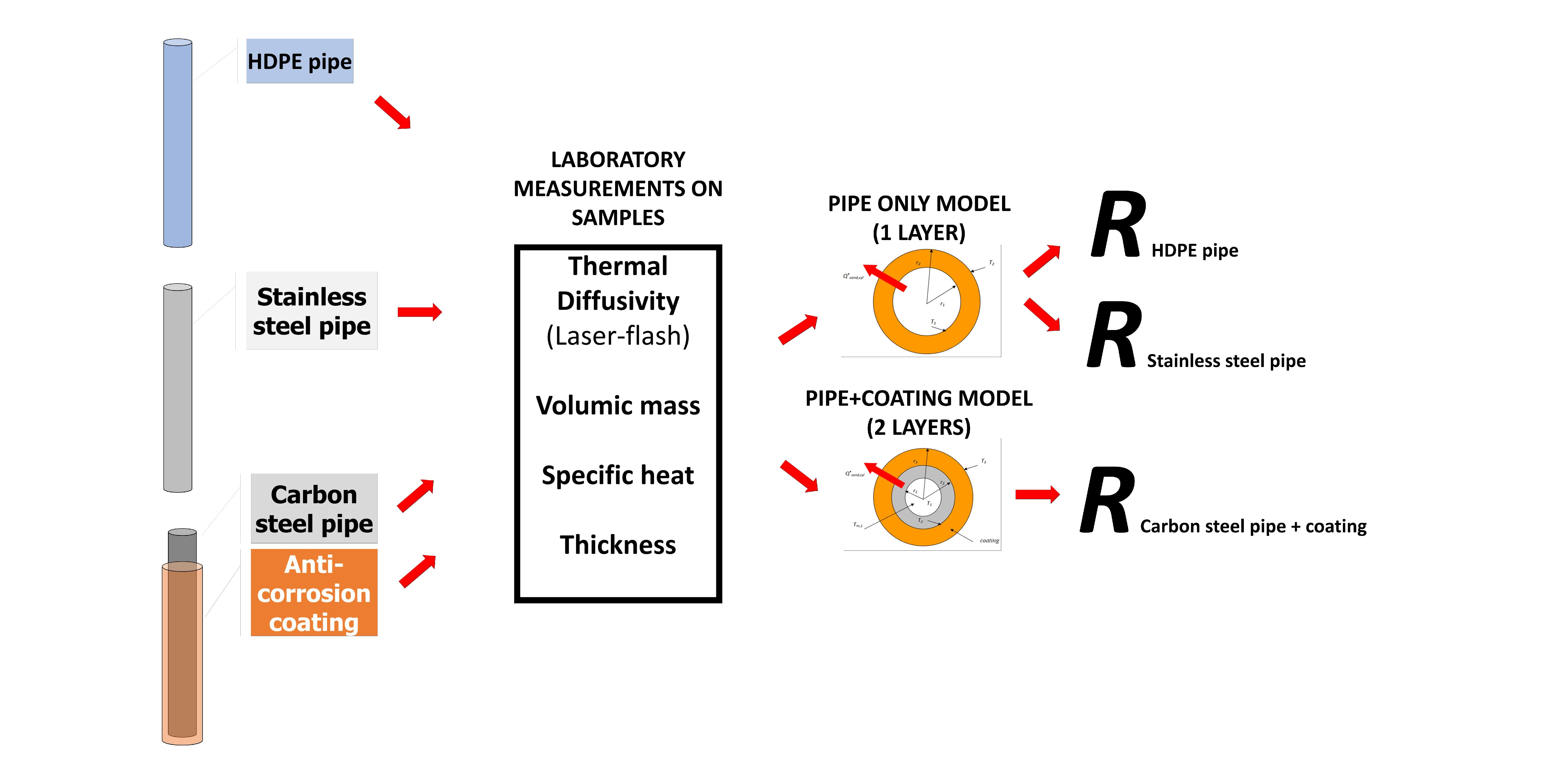
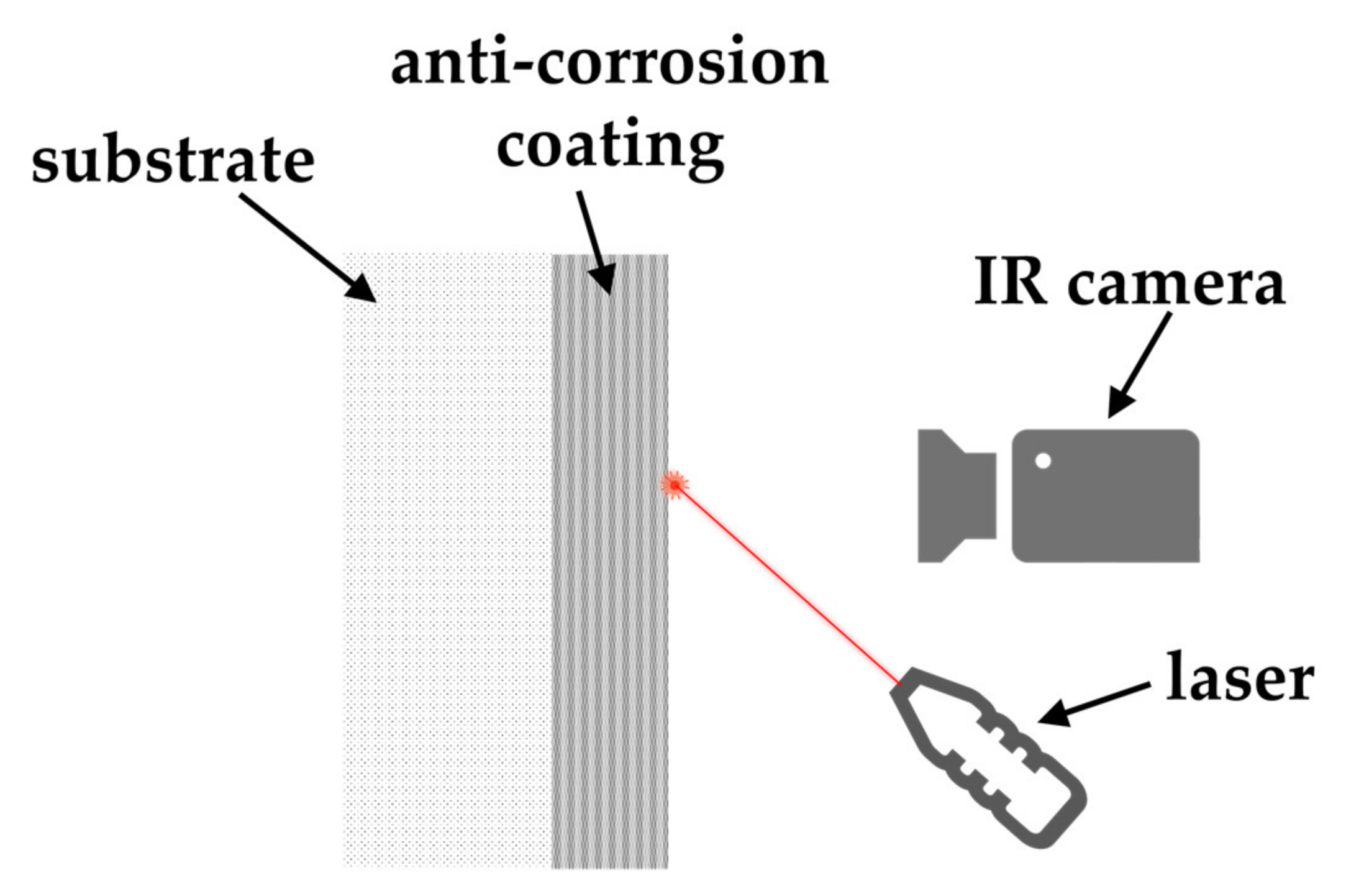
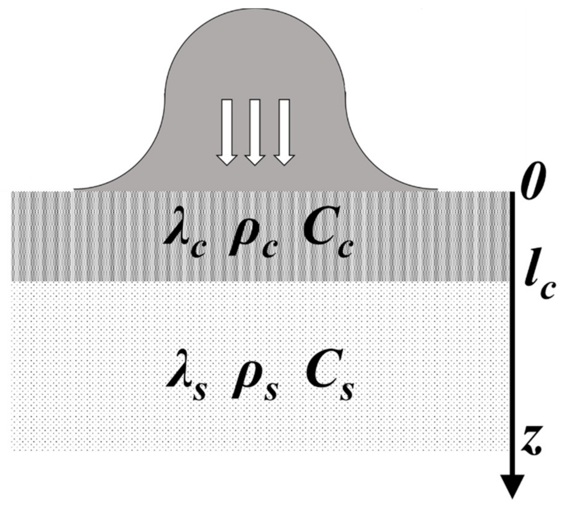
2.3. The LFM Procedure to Measure Thermal Properties

Several methods are available to measure the thermal properties of materials. The laser flash method (LFM), which is one of the most widespread and reliable methods [15,16,17], has been chosen for this work.
In the typical LFM setup, the specimen under the test is stimulated by a heat flux on his front face and a temperature sensor records the temperature increase on the back face of the specimen. The samples are usually disc-shaped ones, sizing in the order of magnitude of 1 cm2, but it could be modified to measure the thermal diffusivity value (α) of other kinds of specimens [18]. This method is popular for different reasons. It is very straightforward, the measurement is not time-consuming, it allows us to test the thermal diffusivities of a wide range of materials, and it can be performed at room temperature but also at very high temperatures. Another advantage is that LFM could provide an indirect evaluation of the thermal conductivity. In fact, after measuring the density (ρ) [19] (e.g., using the Archimedes principle), and the specific heat (cp) (e.g., using the Differential Scanning Calorimetry—DSC) [20], the thermal conductivity (λ) could be obtained as the product of thermal diffusivity, specific heat, and density.
Several manufacturers provide turnkey solutions, while the instrument used in this experiment is based on a commercial solution but has been modified, guaranteeing the same performance level. The instrumentation includes seven elements. The first one is an Nd-doped YAG solid state laser (wavelength of 1064 nm) pumped by two xenon-filled flash lamps. The second one is a sample holder ring made with graphite and molybdenum. It is placed inside the third element, which is a furnace, made of a tantalum foil, allowing for high-temperature measurements. The latter is, in turn, inserted into the fourth element, which is a bell jar with two infrared transparent windows. The fifth element is a dual stage vacuum system, which allows the sample to be placed in vacuum or in gas atmosphere. The sixth element is a Teledyne J10D (InSb, range 2–5.5 µm) detector. It operates in a photovoltaic mode and it is connected to a Teledyne P9 transimpedance amplifier. The final element is a control and data acquisition system, which has been designed to measure the thermal diffusivity of different materials. It adopts a multiple averaging technique [21] that makes it possible to automatically repeat the measurements for a preselected number of times, thus, significantly improving the measured signal-to-noise ratio. Such a technique has been applied to measure the thermal diffusivity of the pipe materials. A typical example of the output is given in Figure 1.
Moreover, the LFM technique allows a single-side configuration, which is very convenient when the material to be tested is a layer of a multi-layer system. This configuration has been applied to study the characteristics of the two protective layers applied as anti-corrosion coating on the steel substrate (bitumen and primer). Figure 2 shows the experimental procedure of the technique used to measure the thermal diffusivity of the coatings. A pulsed laser heats the anti-corrosion coating of the specimen. On the same side, an infrared camera acquires a set of thermal images measuring the temperature evolution on the surface of the sample. The thermal exchange toward the room is neglected [22]. The thermal model of the sample is represented in Figure 3.
The model considers a plane layer (coating) with thickness lc. The other parameters of the models are: the thermal conductivity, the density (ρc), and the specific heat (cc) of the coating. With regard to the substrate, it is considered isotropic and semi-infinite. Its parameters are the thermal conductivity λs, the density ρs, and the specific heat cs. The laser heat pulse is submitted to the observed surface with a Gaussian spatial distribution. It has been demonstrated [23] that, when the temperature integration area includes the entire heated area, the thermal problem is one-dimensional, regardless of the energy distribution of the heating source. Knowing the characteristics of the semi-infinite substrate, the thermal characteristics of the coating are derived.
Figure 3. Schematic diagram of the experiment. Substrate is much thicker than the coating and is considered endlessly extended along the z-axis. On the observed surface, a laser heat pulse is released with a Gaussian spatial distribution [24].
Energies 14 02586 g003
The data acquisition includes images of the temperature evolution in three different stages: before the laser shot (this acts as the reference), during the laser pulse, and after the laser shot, during the cooling stage. In this way, it is possible to analyze the cooling curve after subtracting the baseline reference temperature that is acquired at the beginning of the test. As already depicted in Figure 3, the model consists of a thin layer coating on a semi-infinite substrate (steel sample) [25,26]. A heat pulse (Dirac delta δ(t)) is imposed to the front face of the sample. The temperature T has to satisfy the following equations:
T t = α c z T z ; 0 z l c   ;   t 0
T t = α s z T z ;   z > l c ;   t 0
T(t=0)=0
λ c T z = Q   δ t ;   z = 0
The exact solution on the front face (z = 0) of the specimen is:
T t = Q e c π t 1 + 2 n = 1 Γ n e n 2 l c 2 α c t
  • ec is the effusivity of the coating [J m−2 K−1 s−1/2] e c = ρ c λ c c c ;
  • es is the effusivity of the substrate [J m−2 K−1 s−1/2] e s = ρ s λ s c s ;
  • ρ is the density [kg m−3];
  • λ is the thermal conductivity [W m−1 K−1];
  • c is the specific heat capacity [J kg−1 K−1];
  • Γ is the function of the effusivity of both coating and substrate Γ = e c e s e c + e s ;
  • lc is the thickness of the coating [m];
  • αc is the thermal diffusivity of the coating [m2 s−1] α c = λ c ρ c c c ;
The measured temperature evolution over time can be approximated by Equation (5). The parameters of the analytical solution are optimised in such a way that the analytical solution best fits the experimental data. An example of the data and of the analytical best fit is reported in Figure 4, where they are represented on a log-log scale.
In Equation (5), a few unknown parameters are present.
P = p 1 , p 2 , p 3 = Q e c π , α l 2 , Γ
An iterative procedure changes the previously mentioned parameters in such a way to minimize the error between the experimental data and the mathematical model. Once the condition is achieved, the parameter p2 = α/l2 is known and, therefore, the thermal diffusivity α is also known.
Six different specimens have been measured in order to obtain the thermal diffusivity of HDPE, stainless steels (AISI 304 and AISI 316), carbon steel (S235JRH), and anti-corrosion coatings (bitumen and primer). In Table 2, the thickness values of each specimen are listed. Such values have been measured directly on the samples with a micrometer screw gauge. Bitumen and primer were applied on a carbon steel sample. Their thickness values have been obtained by subtracting the carbon steel thickness from the total thickness of the samples. As a result, their experimental uncertainties are significantly higher than the others.

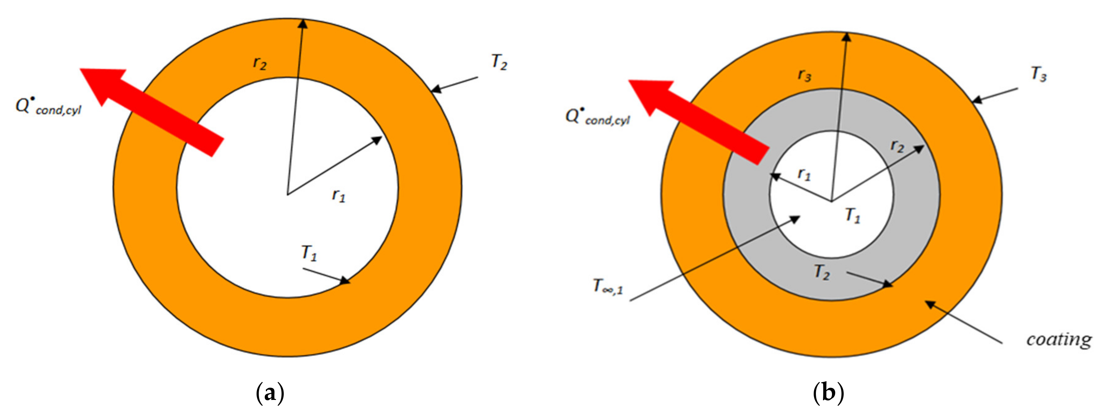
2.4. Modelling the Thermal Resistance of Each Material and of Different GHE Configurations

Several methods are available to model the heat transfer through the pipe, depending on the type and configuration of the heat exchanger [27,28,29]. In this section, a simple pipe model is proposed, with the purpose of comparing different materials. The heat flux Q* exchanged by conduction through the pipe, where the inner temperature T1 is higher than the outer temperature T2, is represented in Figure 5 by a red arrow.
The thermal resistance of a pipe wall is calculated using the following formula:
R p i p e = ln r 2 r 1 2 π λ L
where with reference to Figure 5a:
  • R = the thermal resistance per unit area of the piece of material (m2·K·W−1),
  • r1 = represents the inner radius of the pipe (m),
  • r2 = represents the outer radius of the pipe (m),
  • λ = represents the conductivity of the material (W·m−1·K−1),
  • L = represents the length of the pipe, that is assumed to be unitary (m).
A pipe protected with a coating can be considered to act as two layers of different materials. When materials are positioned in this way, their thermal resistances are added so that the same area conducts less energy for a given temperature difference. Hence, the actual resistance is given by adding the thermal resistance of each layer as an additional piping layer. Equation (7) is modified as follows:
R p i p e + c o a t i n g = R p i p e + R c o a t i n g = ln r 2 r 1 2 π λ p i p e L + ln r 3 r 2 2 π λ c o a t i n g L
where with a reference to Figure 5b:
  • R = the thermal resistance per unit area of the piece of material (m2·K·W−1),
  • r1 = represents the inner radius of the pipe (m),
  • r2 = represents the outer radius of the inner pipe (m),
  • r3 = represents the outer radius of the outer pipe (coating layer) (m),
  • λpipe = represents the conductivity of the carbon steel pipe (W·m−1·K−1),
  • λcoating = represents the conductivity of the coating material (W·m−1·K−1).

3. Results

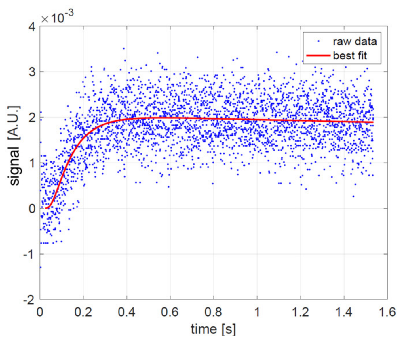
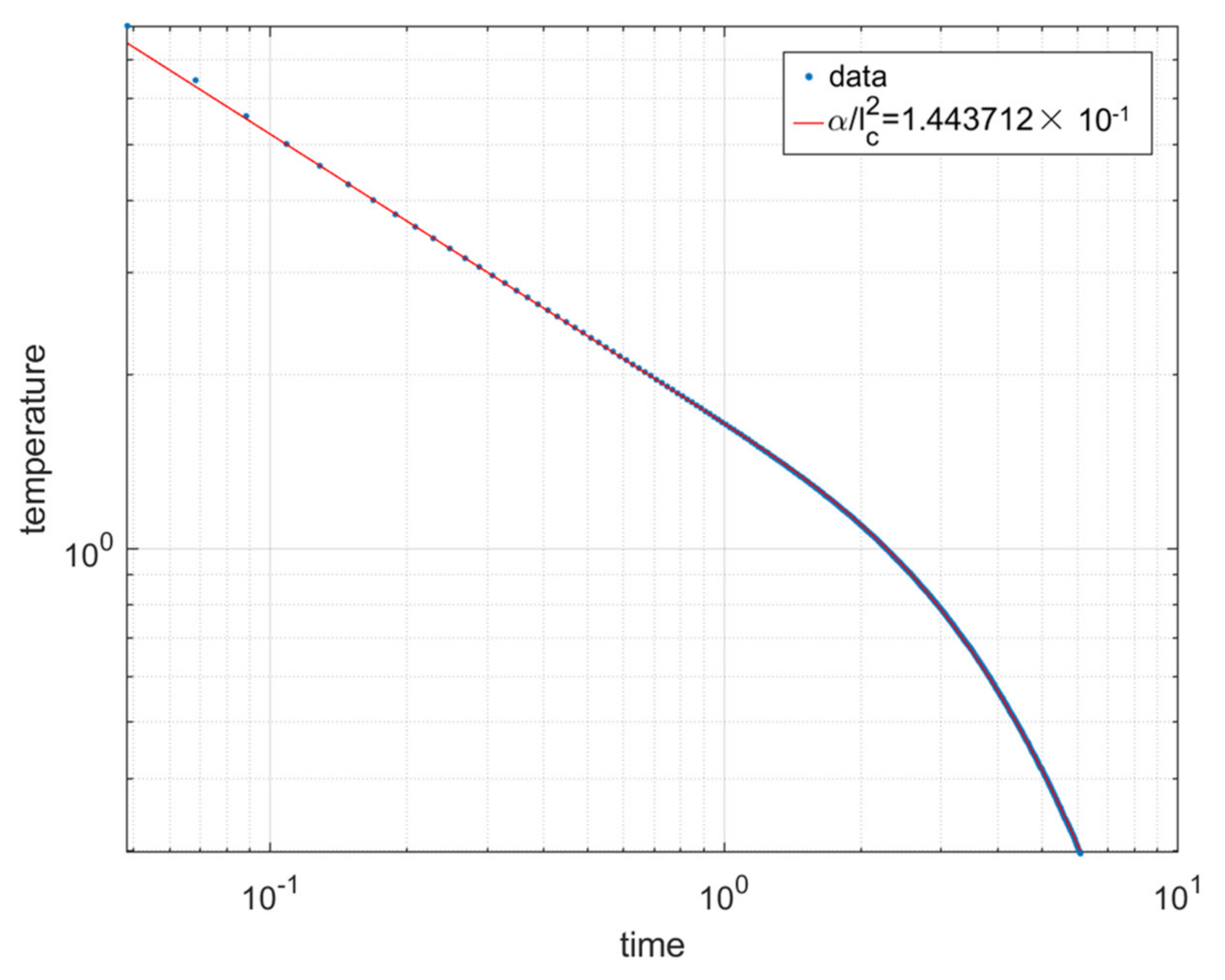
3.1. Outcomes of LFM and Thermal Diffusivity Values

In Table 3, the outcomes of the LFM measurements are listed on the previously mentioned specimens of the materials constituting the pipes and the coatings.
The values are presented before and after taking into account the thickness of each specimen (l).

3.2. Thermophysical Properties of the Specimens

For each material, the density and the specific heat have been measured in order to calculate the thermal conductivity values (Table 4).

3.3. Calculation of the Thermal Resistance of Each Material and of Different GHE Configurations

Given the obtained experimental results, the thermal resistance of each material has been calculated by applying the method reported in Section 2.4. Considering the wall pipe thickness equal to 2 mm, and assuming the outer and the inner radius equal to 82 and 80 mm, respectively, the thermal resistance for each of the considered materials is given as follows:
  • RHDPE = 9585 × 10−6 [m2·K·W−1],
  • RS235JRH = 87 × 10−6 [m2·K·W−1],
  • RAISI316 = 273 × 10−6 [m2·K·W−1],
  • RAISI304 = 243 × 10−6 [m2·K·W−1].
Considering 2 mm of thick carbon steel pipe coated with 0.1 mm of bitumen, the total thermal resistance is:
  • Rbitumen = 97 × 10−6 [m2·K·W−1],
  • Rtotal = RS235JRH + Rbitumen =184 × 10−6 [m2·K·W−1].
Considering the previously described 2 mm of thick carbon steel pipe coated with 0.1 mm of polymeric paint, the total thermal resistance is:
  • RPrimer = 32 × 10−6 [m2·K·W−1],
  • Rtotal = RS235JRH + RPrimer = 120 × 10−6 [m2·K·W−1].
The total thermal resistance of the considered solutions for corrosion-resistant GHEs are listed in Table 5. A wall thickness equal to 2 mm is considered, as it represents a reasonable situation. Among the analyzed configurations are pipe-only solutions (i.e., HDPE, stainless steels) or combination of carbon steel and coatings (i.e., carbon steel with bitumen, carbon steel with primer). The thickness of the coatings is equal to 0.1 mm, which represents a realistic value.

4. Discussion

The results obtained from the experimental tests conducted show that, while the thermal diffusivity of each material varies, and, thus, possibly impacts the dynamic behavior of a shallow geothermal system, the thermal resistance values of the pipes are not so different among the considered configurations. Therefore, they appear not to potentially affect the steady state performance of the GHEs significantly. Exceptions are pipe made of HDPE and unprotected carbon steel.
Notwithstanding the price point, HDPE has, by far, the worst thermal resistance (meaning the highest), making an unfavorable choice for coaxial GHEs in contact with the ground. Therefore, the use of this material could likely find better application with configuration where the grouting is present. As for the carbon steel, which is in the same price range of HDPE, it has the highest thermal conductivity among the measured materials, which is even higher than AISI 304 and AISI 316 stainless steel.
Nevertheless, carbon steel is necessary to use, and, thus, here evaluated, in combination with a coating for corrosion safety reasons. When the bitumen or primer are applied on carbon steel, the resulting thermal resistance is in the same order of magnitude of the stainless steel ones.
Therefore, the choice among stainless steels or carbon steel with coating should be suggested by other aspects, such as the material cost or the compatibility with the characteristics of the subsoil where the GHE has to be installed. For example, in case of gravels or presence of hard rock fragments, it is preferable to not use GHE made of carbon steel with coating because they could damage the coating during the installation phase, even if the new drilling methodology is used. Therefore, these kinds of GHE are preferably installed in finer sediments. In this respect, other anti-corrosion measures should be evaluated. For instance, the galvanic plating with zinc could be possibly favored if the previously mentioned coatings could not withstand the abrasion during the installation. Nonetheless, the weld joints still require bitumen or primer, with possible damages on such spots. This possibility is not considered in the frame of this study, as the small ratio between joints and the entire length of the GHE (up to 120 m or even more) is negligible because it will not affect the thermal performance of the system, even if a low thermal conductivity paint is used. This study demonstrated that there are no particular corrosion-resistant steel pipe configurations that are thermally favorable over others in a critical way. This is valid for the size and geometry of the pipe considered, which are typically used in shallow geothermal installations. However, it can be assumed that, in applications where high external pressure could cause the tube to collapse, and, therefore, the tube must be thick enough to withstand this force, higher conductivity materials may be preferred.

Author Contributions

Conceptualization, G.C. and A.G.; methodology, G.C., A.B. (Alessandro Bortolin), G.F. and P.B.; software, G.C., A.B. (Alessandro Bortolin), G.F. and P.B.; validation, G.C., A.B. (Alessandro Bortolin), G.F. and P.B.; formal analysis, G.C., A.B. (Alessandro Bortolin), G.F. and P.B.; investigation, G.C., A.B. (Alessandro Bortolin), A.G. and P.B.; resources, A.G. and A.B. (Adriana Bernardi); data curation, G.C., A.B. (Alessandro Bortolin), G.F. and P.B.; writing—original draft preparation, G.C.; writing—review and editing, G.C., A.B. (Alessandro Bortolin), G.F., P.B., G.D.S., E.D.S., A.G. and A.B. (Adriana Bernardi); visualization, G.C.; supervision, G.C., G.D.S., A.G. and A.B. (Adriana Bernardi); project administration, A.G. and A.B. (Adriana Bernardi); funding acquisition, A.G. and A.B. (Adriana Bernardi). All authors have read and agreed to the published version of the manuscript.

Funding

This research was funded by H2020 GEO4CIVHIC project, grant number 792355. GEO4CIVHIC project has received funding from the European Union’s Horizon 2020 research and innovation program under grant agreement No. 792355.

Institutional Review Board Statement

Not applicable.

Informed Consent Statement

Not applicable.

Data Availability Statement

Not applicable.

Conflicts of Interest

The authors declare no conflict of interest.

References

  1. Boban, L.; Miše, D.; Herceg, S.; Soldo, V. Application and Design Aspects of Ground Heat Exchangers. Energies 2021, 14, 2134. [Google Scholar] [CrossRef]
  2. Badenes, B.; Sanner, B.; Mateo Pla, M.Á.; Cuevas, J.M.; Bartoli, F.; Ciardelli, F.; González, R.M.; Ghafar, A.N.; Fontana, P.; Lemus Zuñiga, L.; et al. Development of Advanced Materials Guided by Numerical Simulations to Improve Performance and Cost-Efficiency of Borehole Heat Exchangers (BHEs). Energy 2020, 201, 117628. [Google Scholar] [CrossRef]
  3. Pockelé, L.; Mezzasalma, G.; Righini, D.; Vercruysse, J.; Cicolini, F.; Cadelano, G.; Galgaro, A.; Dalla Santa, G.; De Carli, M.; Emmi, G.; et al. Innovative Coaxial Heat Exchangers for Shallow Geothermal. In World Geothermal Congress; Elsevier: Reykjavik, Iceland, 2021. [Google Scholar]
  4. Galgaro, A.; Dalla Santa, G.; Cultrera, M.; Bertermann, D.; Mueller, J.; De Carli, M.; Emmi, G.; Zarrella, A.; Di Tuccio, M.; Pockelé, L.; et al. EU Project “Cheap-GSHPs”: The Geoexchange Field Laboratory. In Energy Procedia; Elsevier: Vienna, Austria, 2017. [Google Scholar] [CrossRef]
  5. Zarrella, A.; Emmi, G.; Graci, S.; De Carli, M.; Cultrera, M.; Dalla Santa, G.; Galgaro, A.; Bertermann, D.; Müller, J.; Pockelé, L.; et al. Thermal Response Testing Results of Different Types of Borehole Heat Exchangers: An Analysis and Comparison of Interpretation Methods. Energies 2017, 10, 801. [Google Scholar] [CrossRef] [Green Version]
  6. Quaggiotto, D.; Zarrella, A.; Emmi, G.; De Carli, M.; Pockelé, L.; Vercruysse, J.; Psyk, M.; Righini, D.; Galgaro, A.; Mendrinos, D.; et al. Simulation-Based Comparison between the Thermal Behavior of Coaxial and Double u-Tube Borehole Heat Exchangers. Energies 2019, 12, 2321. [Google Scholar] [CrossRef] [Green Version]
  7. Mendrinos, D.; Katsantonis, S.; Karytsas, C. Pipe Materials for Borehole Heat Exchangers. In Proceedings of the European Geothermal Congress 2016, Strasbourg, France, 19–23 September 2016; Volume 2016. [Google Scholar]
  8. Mendrinos, D.; Katsantonis, S.; Karytsas, C. Review of Alternative Pipe Materials for Exploiting Shallow Geothermal Energy. Innov. Corros. Mater. Sci. Former. Recent Pat. Corros. Sci. 2017, 7, 13–29. [Google Scholar] [CrossRef]
  9. Tang, F.; Nowamooz, H. Factors Influencing the Performance of Shallow Borehole Heat Exchanger. Energy Convers. Manag. 2019, 181, 571–583. [Google Scholar] [CrossRef]
  10. Zanjani, A.M.; Gharali, K.; Al-Haq, A.; Nathwani, J. Dynamic and Static Investigation of Ground Heat Exchangers Equipped with Internal and External Fins. Appl. Sci. 2020, 10, 8689. [Google Scholar] [CrossRef]
  11. Paul, K.C.; Pal, A.K.; Ghosh, A.K.; Chakraborty, N.R. Thermal Measurements of Coating Films Used for Surface Insulation and Protection. Surf. Coatings Int. Part B Coatings Trans. 2004, 87, 137–141. [Google Scholar] [CrossRef]
  12. UNI 9099:1989, Tubi Di Acciaio Impiegati per Tubazioni Interrate o Sommerse. Rivestimento Esterno Di Polietilene Applicato per Estrusione; UNI: Rome, Italy, 1989.
  13. UNI ISO 5256:1987, Tubi Ed Accessori Di Acciaio Impiegati per Tubazioni Interrate o Immerse. Rivestimento Esterno e Interno a Base Di Bitume o Di Catrame; UNI: Rome, Italy, 1987.
  14. Cadelano, G.; Bortolin, A.; Ferrarini, G.; Molinas, B.; Giantin, D.; Zonta, P.; Bison, P. Corrosion Detection in Pipelines Using Infrared Thermography: Experiments and Data Processing Methods. J. Nondestruct. Eval. 2016. [Google Scholar] [CrossRef]
  15. Parker, W.J.; Jenkins, R.J.; Butler, C.P.; Abbott, G.L. Flash Method of Determining Thermal Diffusivity, Heat Capacity, and Thermal Conductivity. J. Appl. Phys. 1961, 32, 1679–1684. [Google Scholar] [CrossRef]
  16. Akoshima, M.; Baba, T. Thermal Diffusivity Measurements of Candidate Reference Materials by the Laser Flash Method. Int. J. Thermophys. 2005, 26, 151–163. [Google Scholar] [CrossRef]
  17. Jannot, Y.; Degiovanni, A. Thermal Properties Measurement of Materials; ISTE: London, UK, 2018. [Google Scholar] [CrossRef]
  18. Ferrarini, G.; Bison, P.; Bortolin, A.; Cadelano, G.; Rossi, S. Thermal Diffusivity Measurement of Ring Specimens by Infrared Thermography. In Thermosense: Thermal Infrared Applications XXXIX; SPIE: Anaheim, CA, USA, 2017. [Google Scholar] [CrossRef]
  19. Spierings, A.B.; Schneider, M.; Eggenberger, R. Comparison of Density Measurement Techniques for Additive Manufactured Metallic Parts. Rapid Prototyp. J. 2011, 17, 380–386. [Google Scholar] [CrossRef]
  20. O’Neill, M.J. Measurement of Specific Heat Functions by Differential Scanning Calorimetry. Anal. Chem. 1966, 38, 1331–1336. [Google Scholar] [CrossRef]
  21. Ferrarini, G.; Bortolin, A.; Cadelano, G.; Finesso, L.; Bison, P. Multiple Shots Averaging in Laser Flash Measurement. Appl. Opt. 2020, 59, E72–E79. [Google Scholar] [CrossRef]
  22. Bison, P.; Clarelli, F.; Vannozzi, A. Pulsed Thermography for Depth Profiling in Marble Sulfation. Int. J. Thermophys. 2014, 36, 1123–1130. [Google Scholar] [CrossRef]
  23. Bison, P.G.; Cernuschi, F.; Grinzato, E.; Marinetti, S.; Robba, D. Ageing Evaluation of Thermal Barrier Coatings by Thermal Diffusivity. Infrared Phys. Technol. 2007, 49, 286–291. [Google Scholar] [CrossRef]
  24. Bison, P.; Cernuschi, F.; Grinzato, E. In-Depth and in-Plane Thermal Diffusivity Measurements of Thermal Barrier Coatings by IR Camera: Evaluation of Ageing. Int. J. Thermophys. 2008, 29, 2149–2161. [Google Scholar] [CrossRef]
  25. Balageas, D.L.; Krapez, J.C.; Cielo, P. Pulsed Photothermal Modeling of Layered Materials. J. Appl. Phys. 1986, 59, 348–357. [Google Scholar] [CrossRef]
  26. Luo, Y.; Xu, G.; Yan, T. Performance Evaluation and Optimization Design of Deep Ground Source Heat Pump with Non-Uniform Internal Insulation Based on Analytical Solutions. Energy Build. 2020, 229, 110495. [Google Scholar] [CrossRef]
  27. Lamarche, L.; Kajl, S.; Beauchamp, B. A Review of Methods to Evaluate Borehole Thermal Resistances in Geothermal Heat-Pump Systems. Geothermics 2010, 39, 187–200. [Google Scholar] [CrossRef]
  28. De Carli, M.; Tonon, M.; Zarrella, A.; Zecchin, R. A Computational Capacity Resistance Model (CaRM) for Vertical Ground-Coupled Heat Exchangers. Renew. Energy 2010, 35, 1537–1550. [Google Scholar] [CrossRef]
  29. Carslaw, H.S.; Jaeger, J.C. Conduction of Heat in Solids; Oxford University Press: Oxford, UK, 1980. [Google Scholar]
Figure 1. Results of the AISI 304 specimen measurements given as an example of the raw output. Experimental data and fitting curve for the average of 100 shots [21].
Energies 14 02586 g001
Figure 2. Experimental setup of in-plane and in-depth thermal diffusivity measurement.
Energies 14 02586 g002
Figure 4. Log-log representation of the spatial average of the surface temperature in time given as an example of the processed output. The red line is the fit curve calculated on the experimental data (blue points).
Energies 14 02586 g004
Figure 5. Heat flux exchanged by conduction in a pipe where the inner temperature is higher than the outer one. Left side (a) is a single layer pipe and the right side (b) is a pipe with a coating layer (not in scale).
Energies 14 02586 g005
Table 1. Market price of reference materials (Source: Milano Finanza/Camera di Commercio di Milano. Average market price from the producer/importer to the industry, VAT excluded).
Material€/ton
HDPE1080
Mild/low-carbon steel900
Stainless steel AISI 3042900
Stainless steel AISI 3163480
Table 2. Thickness of the specimens: pipe materials and coatings.
SpecimenThickness [mm]
HDPE0.570 ± 1%
Stainless steel AISI 3041.024 ± 0.5%
Stainless steel AISI 3161.100 ± 0.5%
Carbon steel S235JRH5.486 ± 0.5%
Bitumen0.657 ± 4%
Primer0.150 ± 12%
Table 3. Outputs of the LFM measurement of the specimens.
SpecimenEstimated Parameter α/l2
[s−1]
Thermal Diffusivity
[m2 s−1]
HDPE0.708 ± 0.4%0.23 × 10⁻⁶ ± 5%
Stainless steel AISI 3043.96 ± 0.5%4.1 × 10⁻⁶ ± 5%
Stainless steel AISI 3162.98 ± 0.5%3.6 × 10⁻⁶ ± 5%
Carbon steel S235JRH0.422 ± 0.5%12.7 × 10⁻⁶ ± 5%
Bitumen0.176 ± 0.4%0.08 × 10⁻⁶ ± 9%
Primer11.21 ± 0.5%0.25 × 10⁻⁶ ± 25%
Table 4. Thermophysical properties of the specimens.
MaterialSpecific Heat
[J·kg−1·K−1]
Density
[kg·m−3]
Thermal Conductivity [W·m−1·K−1]
HDPE1930 ± 2%940 ± 2.5%0.41 ± 5%
Stainless steel AISI 304500 ± 5%7850 ± 2.5%16.2 ± 7.5%
Stainless steel AISI 316500 ± 5%8000 ± 2.5%14.4 ± 7.5%
Carbon steel S235JRH460 ± 5%7700 ± 2.5%45 ± 7.5%
Bitumen1720 ± 5%1500 ± 2.5%0.20 ± 10%
Primer1100 ± 5%2200 ± 2.5%0.62 ± 27%
Table 5. Thermal resistance of different corrosion-resistant, pipe-coating systems, and how they compare to an unprotected carbon steel pipe 2 mm thick.
Corrosion-Resistant
Pipe Configuration
Total
Thermal Resistance
[m2·K·W−1]
Increased Thermal Resistance Compared to Unprotected Carbon Steel
2 mm thickness HDPE9585 × 10−6×110
2 mm thickness stainless steel AISI 304243 × 10−6×2.8
2 mm thickness stainless steel AISI 316273 × 10−6×3.1
2 mm thickness Carbon steel S235JRH coated with 0.1 mm of bitumen184 × 10−6×2.1
2 mm thickness carbon steel S235JRH coated with 0.1 mm of primer120 × 10−6×1.4
Publisher’s Note: MDPI stays neutral with regard to jurisdictional claims in published maps and institutional affiliations.

