Article

An Energy-Harvesting System Using MPPT at Shock Absorber for Electric Vehicles

1
Department of Energy and Power Conversion Engineering, University of Science & Technology, 12 Bulmosan-ro 10 beon-gil, Seongsan-gu, Changwon-si 51543, Korea
2
Electric Machines and Drives Research Center, Korea Electrotechnology Research Institute, 12 Bulmosan-ro 10 beon-gil, Seongsan-gu, Changwon-si 51543, Korea
*
Author to whom correspondence should be addressed.
Energies 2021, 14(9), 2552; https://doi.org/10.3390/en14092552
Submission received: 23 March 2021 / Revised: 27 April 2021 / Accepted: 27 April 2021 / Published: 29 April 2021
(This article belongs to the Special Issue Energy Harvesting Systems: Analysis, Design and Optimization)

Abstract

:
This paper investigates an energy-harvesting system that uses of vibration energy at a shock absorber for electric vehicles. This system mainly comprises a linear electromagnetic generator and synchronous buck converter. To obtain the electrical energy through a linear electromagnetic generator, the perturb and observe maximum power point tracking (P&O MPPT) scheme is applied at the converter. The power converter circuit is designed with a diode rectifier and synchronous buck converter. The generated electric power is able to transmit to the battery and the damping force of the shock absorber is adjusted by the controlled current of generator. The linear electromagnetic generator was designed as a single phase eight-slot eight-pole tubular permanent magnet machine. The performance of the proposed energy-harvesting system was verified through simulations and experiments.

1. Introduction

Automobiles have been used for a long time as transportation and this has led to environmental problems caused by their exhaust gases and fuel consumption [1]. To solve these environmental problems, automobile technologies are actively being developed such as electric and hybrid vehicles that use electrical energy. As rapid advancements in technology result in the greater number of electric vehicles being developed, the demand for various electric parts will be on the rise in the future. Thus, electrical energy will play a crucial role in addressing this issue. Therefore, various forms of energy-harvesting techniques for converting additional energy sources into electrical energy have recently been researched [2,3].
Energy-harvesting refers to the collection of energy that is not utilized, such as noise, heat, and vibration energy, and its conversion into usable electrical energy. The energy-harvesting technology using the vibration energy obtains the highest power capacity among other energy sources [4,5]. Conventional shock absorbers have been used to absorb shocks from road surfaces while driving and convert this vibration energy to the heat energy in the suspension. If these shock absorbers were changed to an energy harvesting system, the produced vibration energy could be used as another electrical energy source for assisting the generator capacity of a vehicle or charging a secondary battery [6,7]. In addition, it has a high power density and is not restricted by the space used [8]. Energy-harvesting shock absorber can be also installed in the suspension of a general vehicle. Recently, there are many researched papers for energy-harvesting from vehicle shock absorber systems and it is generally report that the electrical power generated by the energy-harvesting shock absorber is approximately 5–400 W [9,10,11]. Hence, a generator with a simple structure and a high energy recovery power conversion is required in such a low-power generation system. However, most studies primarily focus on rotary electromagnetic shock absorber and rarely mention power converter system.
This paper focuses on the design of a linear electromagnetic generator and a power converter for an energy-harvesting system with the function of a shock absorber under irregular rough vibration conditions. The entire configuration of energy-harvesting suspension system for the electric vehicle is shown in Figure 1.
The designed linear electromagnetic generator is a linear permanent magnet synchronous type with a Halbach array to increase the power density and capacity. The generated electric power is able to transmit to the battery and the damping force of the shock absorber is adjusted by the controlled current of generator which is defined by an adequate perturb and observe maximum power point tracking (P&O MPPT) control scheme. Since the damping force of the designed shock absorber generally operates in the low-frequency range of approximately 10 Hz, this MPPT control scheme can achieve generated power control of the generator and absorb the vibration of the electric vehicle without the need of expensive position sensors.
A large number of papers focused on energy harvesting power electronic interfaces with the P&O MPPT algorithms, which is widely applied in products, to recovery high power energy. However, the output performance was not enough to improve the fuel efficiency of the vehicle or to use it as a secondary energy [12,13,14,15].
The proposed energy-harvesting generator was designed for a maximum and average power of 250 W and 100 W, respectively. The validity of the proposed energy-harvesting suspension system was verified by the simulation and experiment results.

2. Linear Electromagnetic Generator

The energy-harvesting suspension system using the vibration energy of a vehicle has a high power density and is not restricted by space used. It can be easily installed at the shock absorber of a general vehicle. The energy-harvesting technology using the vibration energy can be divided into piezoelectric, electrostatic, and electromagnetic methods. Although piezoelectric generators reduce the cost and can easily post process, the generated power is remarkably small compared with electromagnetic generators [16]. Electromagnetic harvesting has the advantages of high power and divided into a linear generator [17,18,19] and a rotary generator [20,21]. The linear electromagnetic generator is directly converted the vibration energy to the electrical power without a separate mechanical gear, thus it has the advantages of a simpler structure, compact size, light weight, and easy maintenance compared with a rotary generator [22,23].
The principle of generated power is based on Lenz’s law. Induction electromotive forces are generated in the direction of generating an induced magnetic field, which is the opposite of the change in magnetic flux caused by the magnetic field passing through the coil. Hence, the electrical energy is generated from the vibration of a mover. The overview of linear electromagnetic generator design with the one pole pitch is shown in Figure 2. This shows that coil, iron tooth, spacer, permanent magnet (PM) cover, axial PM and insulation are attached to the damping body part. The generator is composed of eight slots—eight poles, and two PM poles are added such that the coil winding is always inside the excited magnetic flux density field. This linear electromagnetic generator targets vehicles driving on a class C road at 60 mph. Under these conditions, peak-to-peak stroke and vibration speed of 11.25 mm and 0.25 m/s, respectively, are required [9]. To maintain the 0.25 m/s vibration speed, the vibration frequency is calculated by:
f = v r m s 2 S t r o k e p e a k t o p e a k   π
where f is the vibration frequency, vrms is the rms vibrating speed and Strokepeak-to-peak is the peak-to-peak stroke length of the generator.
The induced electromotive force V, generated maximum current Imax, and maximum power Pmax are given as follows [11,24,25]:
V = v l B   sin ( π 2 ) = B v l
I m a x = V R = σ B v A w
P m a x = V I m a x = B 2 v 2 l σ A w
where v is the velocity, l is the length of the conductor, B is the magnetic flux density, σ is the electrical conductivity, Aw is the cross-sectional area of the conducting wire, and R is the coil resistance.

3. Active Power Converter for Energy-Harvesting Systems

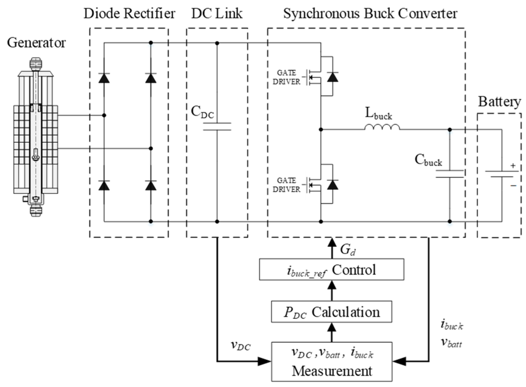
The proposed energy harvesting power converter is divided into two parts: a rectifier and a synchronous buck converter. In the case of a low power system, the rectifier is configured as a diode rectifier because a power converter such as a pulse width modulation (PWM) converter has higher energy loss and is complicated to control. MOSFET (metal-oxide-semiconductor field-effect transistor) is used in the lower sub-circuit at synchronous buck converter instead of a diode because it has less heat loss [26]. Battery current is controlled by a synchronous buck converter and it is affect to power of the energy-harvesting generator. The damping forces of the shock absorber are adjusted as this continues to transmit the generated power.

3.1. Diode Rectifier of the DC Link Capacitance Design

The DC link capacitance (CDC_link) of the diode rectifier can be expressed by Equation (5). The value of CDC_link affects the DC link voltage ripple and is selected to meet the voltage ripple requirement at the rated speed of the generator according to [27]:
C D C _ l i n k = P D C _ l i n k 6 ( 2 π f r s ) v n o m _ D C Δ v D C
where PDC_link is the average output power of the diode rectifier, frs is the harvesting generator fundamental electrical frequency at the rated speed, vnom_DC is the nominal DC link voltage, and ΔvDC is the allowable voltage ripple.

3.2. Synchronous Buck Converter Design Specifications

The inductance (Lsyn_buck) and capacitance (Csyn_buck) of the synchronous buck converter are determined using Equations (6) and (7). The design of the synchronous buck converter inductor value affects not only the current capacity, but also the current ripple of the inductor. The design of the capacitor value affects the buck converter output voltage, the output voltage overshoot and the response time of the output feedback loop:
L s y n _ b u c k = ( v i n v o u t )   D L I R · I O U T , m a x   f s w
C s y n _ b u c k = L i p k 2 ( v o v + v o u t ) 2 v o u t 2
where vin is the input voltage of the synchronous buck converter, vout is the output voltage of the synchronous buck converter, D is the duty cycle of the circuit, and LIR is the inductor current ripple ratio. LIR is the variation current divided by the output current. IOUT, max is the maximum output current of the inductor, fsw is the MOSFET switching frequency, L is the buck converter output inductor, ipk is the peak current of the inductor, and vov is the output voltage maximum overshoot. The inductance and capacitance values of the synchronous buck converter were respectively set to 520 μH and 114 μF with 20% tolerance value. All parameters of the designed energy- harvesting system are listed in Table 1.
Values of some of the parameters, such as power level, input voltage, and load resistor (coil resistance of the generator), are based on the optimal design of the generator and chosen a priori. Values of other parameters were chosen by the designer as targets.
The bandwidth of the control loop of the synchronous buck converter is near 7.7 kHz. The control frequency of the MPPT algorithm is 800 Hz due to the influence of 40 kHz switching frequency and 50 control loops.

3.3. P&O MPPT (Perturb and Observe Maximum Power Point Tracking) Algorithm

This energy-harvesting system does not generate constant energy because the generated power is changed by the driving speed and irregular road conditions. Therefore, it is important to obtain the maximum output to be supplied to the secondary battery, even under rapidly changing road conditions. Maximum power point tracking (MPPT) control is an algorithm [28] for estimating the maximum output of the generator, and the maximum generator output information can be estimated from the voltage and current of the energy-harvesting generator. The MPPT algorithm eliminates the need for position and speed measurement equipment to detect the damping force of the shock absorber of the vehicle while tracking the maximum power of the generator. The P&O algorithm is one of the MPPT control schemes [29] and has been adapted to this energy-harvesting system. The output current of the synchronous buck converter is periodically increased and decreased by a small step size, and the previous output power is compared with the actual output power to find the maximum power operating point.
Conventional P&O method perturb the operating point for tracking the maximum power point. Hence, increasing or decreasing the control parameter using a fixed step size. The measured previous and real generator output power is using for the perturbation. This conventional P&O algorithm always has a trade-off between the magnitudes of the step size. The oscillation of the output power can be reduced at a steady state with a low step size. However, this leads to a response delay in the system [30,31]. The opposite result is occurred in the case of a high step size. Hence, an appropriate step size is required at the P&O MPPT method. The proposed P&O algorithm is shown in Figure 3 and explained as follows:
(1)
The DC link voltage is compared with the battery voltage, and if the DC link voltage is less than the battery voltage, the buck converter does not operate.
(2)
Total power is calculated using the sampled DC link voltage and current.
(3)
The amount of change in the output is calculated through 50 control loops.
(4)
According to the overall output change, the current reference command value is applied to calculate the amount of current change required to determine imppt.
(5)
The steps are repeated while operating with the calculated current reference:
K = 1 v b a t t
In this algorithm, the synchronous buck converter current is perturbed to track the maximum output power. The reciprocal of the battery voltage, which is shown at Equation (8), is determined as the magnitude of the perturbation constant, which is determined as the reference current by multiplying the total power change. A fixed step size was not used as the perturbation constant. It should be noted that the proposed algorithm uses the rate of change of the synchronous buck converter current owing to the relatively fixed battery voltage. The DC link and battery voltage were determined as sampling standards. The duty cycle is reflected by DC link voltage divided by the output voltage. The validity of the designed energy-harvesting system was performed using PLECS version 4.4 simulation tool and the overall active power converter of structure is shown in Figure 4 with the MPPT algorithm.
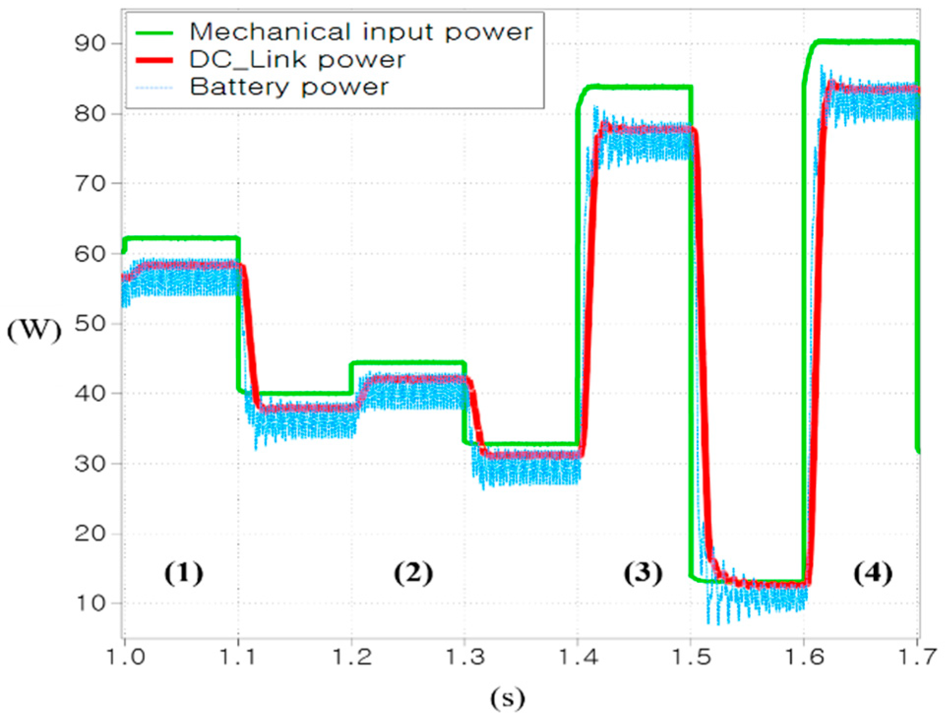
The proposed algorithm simulation result of the current variation under the discrete torque is compared with the fixed step size as shown in Figure 5. It was confirmed that the proposed step size is suitable for the fluctuation of the perturbation current as shown in Figure 5a. However, the fixed step size of conventional P&O MPPT algorithm shows unstable results under rapidly varying torque conditions in Figure 5b. Figure 6 shows the power of the mechanical input, DC link, and battery using the proposed P&O MPPT algorithm with the optimized coefficient value. The mechanical input torque was randomly applied from 0.1 Nm to 1 Nm to simulate irregular rough road conditions.
The mechanical, rectifier and battery power are calculated using Equations (9)–(11), where ω is the angular speed, T is the input torque of the generator, vDC is the DC link voltage, iDC is the DC link current, vBatt is the battery voltage and iBatt is the battery current:
P M e c h a n i c a l   p o w e r = ω T
P R e c t i f i e r   p o w e r = v D C i D C
P B a t t e r y   p o w e r = v B a t t i B a t t
The mechanical input power changes according to the varied torque, and during the rectification process, diode conduction loss occurred and the power of the DC link was slightly reduced. Battery power using MPPT is in accordance with the DC link power, and the efficiency of the diode rectifier, which is calculated using Equations (12) and (13) where η is the efficiency. Table 2 shows the mechanical, rectifier and battery output power from the four sections of Figure 6 with efficiency. This shows that the MPPT efficiency is near 90%, which is a good performance for an energy-harvesting system:
η r e c t i f i e r = P R e c t i f i e r   p o w e r P M e c h a n i c a l   p o w e r · 100 %
η M P P T = P B a t t e r y   p o w e r   P M e c h a n i c a l   p o w e r · 100 %

4. Energy-Harvesting Generators and Power Converter Prototype

The components of the linear generator are largely composed of a stator assembly and a mover assembly. The detailed components of the stator assembly are composed of a core, coil, cover, yoke, and bobbin. The detailed components of the mover assembly are composed of a magnet, spacer, magnet protective cover, permanent magnet, and shaft. In addition, a plastic grommet was developed to protect the coil when the coil was drawn out, and an oil seal was developed to prevent oil leakage. The peak-to-peak stroke length of the designed generator is 12 mm. The overall assembly of the components and final prototype are shown in Figure 7.
The power converter for MPPT control consists of a current, voltage and displacement measurement sensor and a digital signal processor control board in the form of a single 48 V power supply. The final power converter is divided into two layers, as shown in Figure 8a. The main digital devices, which are mentioned above, are located at the top, and power components including DC link capacitors are located at the bottom. Based on the 3D modeling, the final prototype power converter for the energy-harvesting system of the vehicle is shown in Figure 8b. The manufactured prototype power converter has a width, length, and height of 15, 20, and 10 cm, respectively. The volume can be reduce through an optimal design when installed in an actual vehicle in the future.

5. Results

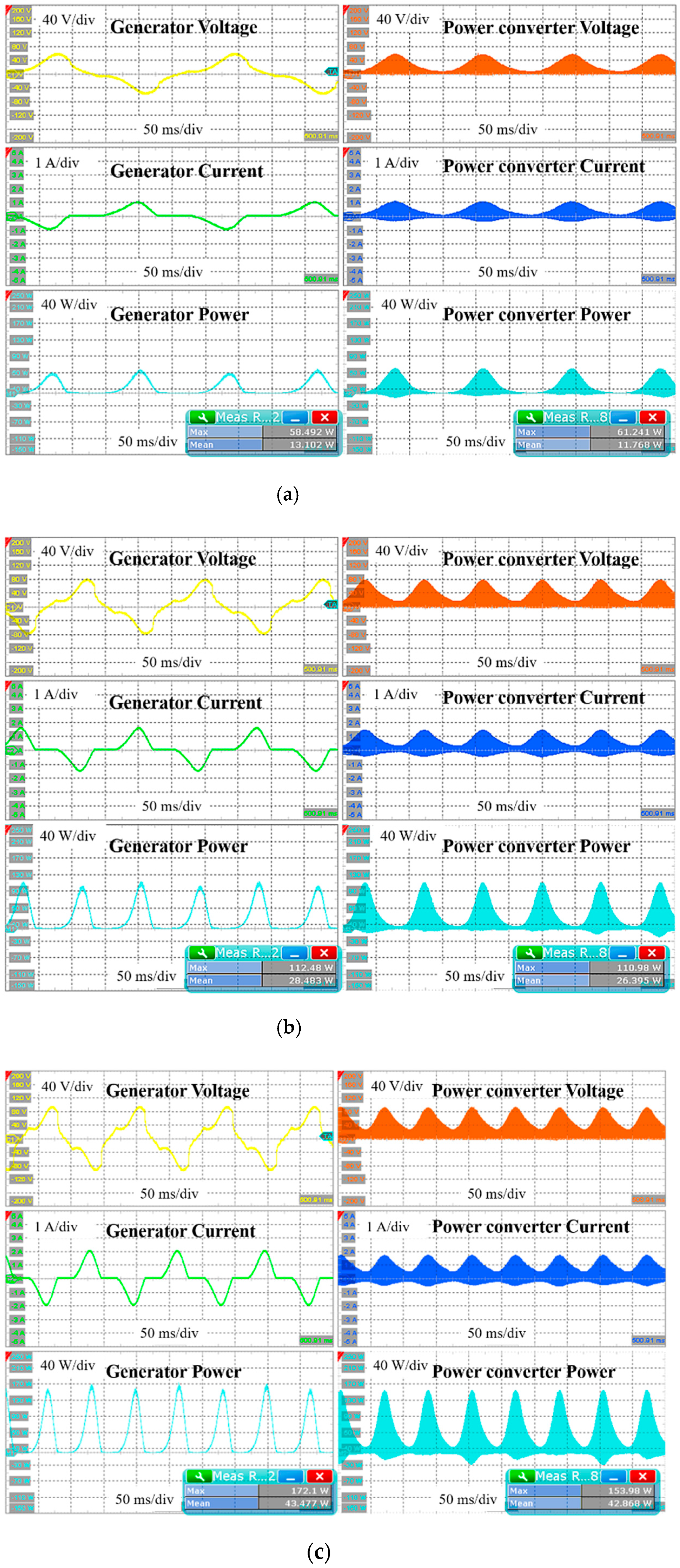
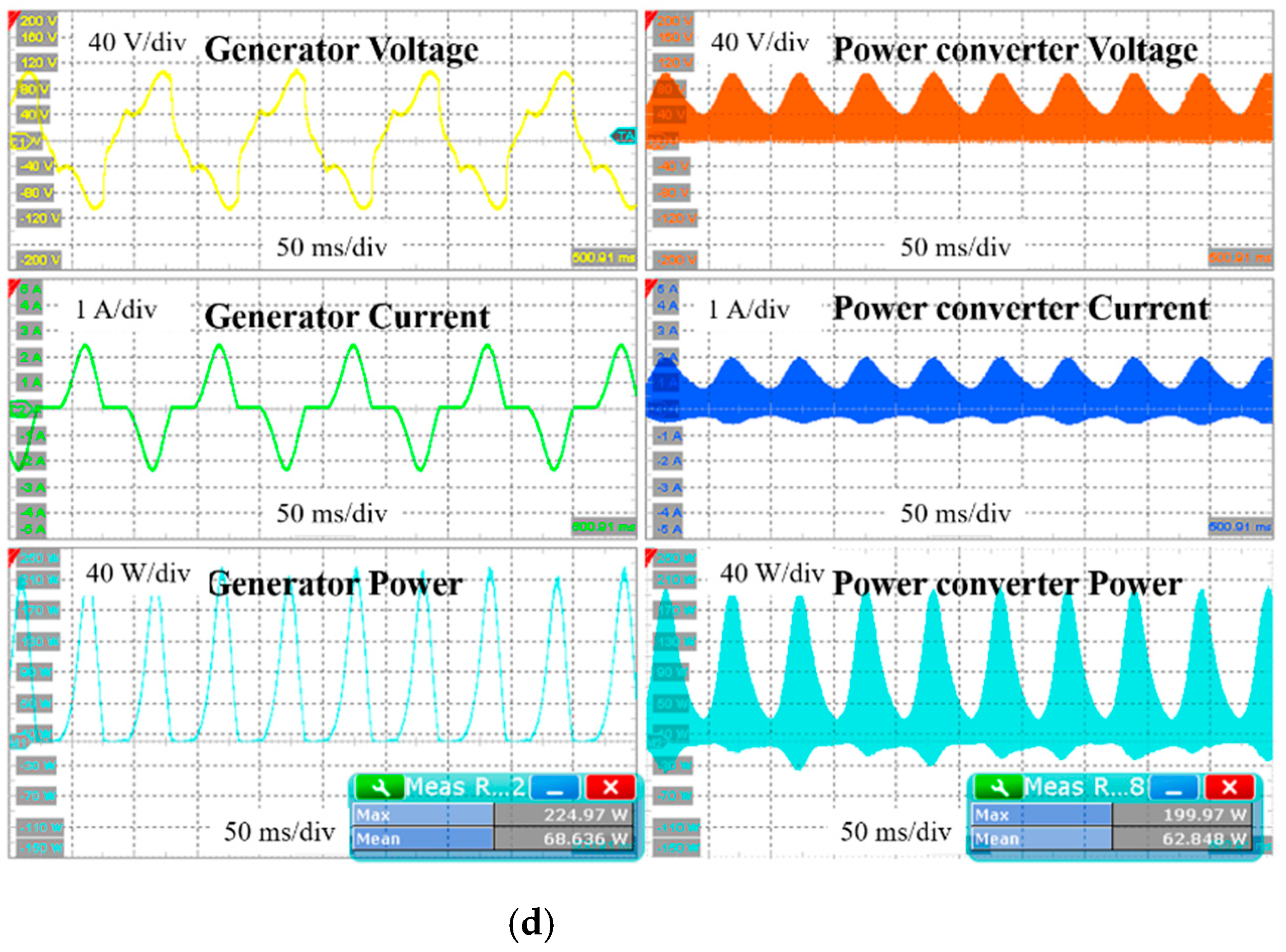
The test setup comprised a power converter, a linear machine, an oscilloscope, and an electronic load. Based on the modeling described in the previous section, the output of the generator for each vibration speed and the output of the power converter were compared considering the irregular road conditions and driving speed. It should be noted that to generate the vibrating motion, the moving part and PM layer are connected to the sub-motor by a shaft. The rated speed of the sub motor was 1500 r/min, the maximum speed was 3000 r/min, and the gear ratio of the linear machine and sub motor was 1:5. Under these conditions, the vibration speed of 0.25 m/s is the same speed as the 2813.5 r/min rotational speed, which almost reaches the maximum possible rotational speed of the sub-motor. Considering these characteristics, the vibration speed was performed in the range of 0.1–0.25 m/s. The environment of the test setup is illustrated in Figure 9.
The waveform of the performance evaluation using vertical excitation for the energy-harvesting linear generator is shown in Figure 10. Based on the maximum vibration speed, the maximum and average powers of the generator were approximately 225 W and 69 W, respectively, which were slightly lower than the design target. The differences and errors during the manufacturing process affect the generator performance. The maximum and average power outputs of the power converter were approximately 200 W and 63 W, respectively. The efficiency of the power converter is expressed as the ratio between the converter and the linear machine output power as shown in Equation (14). The efficiency of the maximum vibration speed section was 91.6%, and the efficiency of the entire section is listed in Table 3.
η p o w e r   c o n v e r t e r = P c o n v e r t e r   p o w e r   P M a c h i n e   p o w e r · 100 %
The goal of this approach is to operate a power converter under irregular modes using the MPPT algorithm. From these results, it is clear that this approach provides a solution for energy-harvesting systems in shock absorbers.

6. Conclusions

In this paper, a proposed variable step size was adapted to the P&O MPPT algorithm for applying the energy-harvesting technique in the shock absorbers in a vehicle suspension and the active output control performance of an active power converter was analyzed. This analysis was performed under irregular input conditions and the energy utilization of the system was calculated. The synchronous buck converter current follows the generated power by the continuous perturbation. The proposed method provides continuous power to the battery regardless of the generator’s position and speed, thus eliminating the need for expensive positioning and speed measurement sensors. The results of the simulation and experiment demonstrate that the converter followed the rectified maximum power without the generator information. Future work will include selecting a vehicle to install the proposed energy harvesting system and analyzing characteristics according to driving by various actual road conditions. This energy harvesting system can be widely applied to existing vehicles, electric and hybrid vehicles, etc., and can be used as an ESS (Energy Storage System) for improving combat power, operating radius, and extending operation time when performing military operations.

Author Contributions

Conceptualization, Y.C. and B.P.; methodology, B.P.; software, J.L.; validation, J.L. and B.P.; formal analysis, J.L.; investigation, J.L.; resources, Y.C. and B.P.; writing—original draft preparation, J.L.; writing—review and editing, J.L., J.K. and B.P.; visualization, J.L.; supervision, B.P.; project administration, Y.C.; funding acquisition, Y.C. All authors have read and agreed to the published version of the manuscript.

Funding

The research work presented here was carried out at Electric Machines and Drives Research Center, Korea Electrotechnology Research Institute (KERI) and supported in part by the Civil-Military Technology Cooperation Program (No.: 16-CM-EN-17), funded by the Defense Acquisition Program Administration and the Ministry of Trade, Industry & Energy in Korea.

Institutional Review Board Statement

Not applicable.

Informed Consent Statement

Not applicable.

Data Availability Statement

Some or all data, models generated, or used during the study are available in a repository or online.

Acknowledgments

This work was made possible by a grant from the Civil-Military Technology Cooperation Program (No:16-CM-EN-17) funded by the Defense Acquisition Program Administration and the Ministry of Trade, Industry & Energy in Korea.

Conflicts of Interest

The authors declare no conflict of interest.

References

  1. Paolo, L.; Vincenzo, C.; Aldo, C. Economic and environmental sustainability of Dynamic Wireless Power Transfer for electric vehicles supporting reduction of local air pollutant emissions. Renew. Sustain. Energy Rev. 2021, 138, 110537. [Google Scholar]
  2. Zhang, R.; Wang, X.; John, S. A Comprehensive Review of the Techniques on Regenerative Shock Absorber Systems. Energies 2018, 11, 1167. [Google Scholar] [CrossRef] [Green Version]
  3. Pornrawee, T.; Sontipee, A.; Pitak, L.; Raj, D. Thermomechanical Effects on Electrical Energy Harvested from Laminated Piezoelectric Devices. Crystals 2021, 11, 141. [Google Scholar]
  4. Hamid, J.; Sheeba, R.; Sofiya, S. Energy Harvesting through Regenerative Braking using Hybrid Storage System in Electric Vehicles. In Proceedings of the IEEE International Conference on Intelligent Techniques in Control, Optimization and Signal Processing (INCOS), Tamilnadu, India, 11–13 April 2019. [Google Scholar]
  5. Aliakbari, A.; Vahidinasab, V. Optimal Charging Scheduling of Solar Plugin Hybrid Electric Vehicles Considering On-the-Road Solar Energy Harvesting. In Proceedings of the 2020 Smart Grid Conference (SGC), Kashan, Iran, 16–17 December 2020. [Google Scholar]
  6. Zou, J.; Guo, X.; Xu, L.; Tan, G.; Zhang, C.; Zhang, J. Design, Modeling, and Analysis of a Novel Hydraulic Energy-Regenerative Shock Absorber for Vehicle Suspension. Shock. Vib. 2017, 3186584. [Google Scholar] [CrossRef]
  7. Abdelkareem, M.A.A.; Xu, L.; Ali, M.K.A.; Elagouz, A.; Mi, J.; Guo, S.; Liu, Y.; Zuo, L. Vibration energy harvesting in automotive suspension system: A detailed review. Appl. Energy 2018, 229, 672–699. [Google Scholar] [CrossRef]
  8. Dibin, Z.; Michael, J.-T.; Stephen, P.-B. Strategies for increasing the operating frequency range of vibration energy harvesters: A review. Meas. Sci. Technol. 2009, 21, 1–29. [Google Scholar]
  9. Zuo, L.; Zhang, P.S. Energy Harvesting, Ride Comfort, and Road Handling of Regenerative Vehicle Suspensions. J. Vib. Acoust Trans. ASME 2013, 135, 1–8. [Google Scholar] [CrossRef]
  10. Xiudong, T.; Teng, L.; Zuo, L. Design and Optimization of a Tubular Linear Electromagnetic Vibration Energy Harvester. IEEE/ASME Trans. 2014, 19, 615–622. [Google Scholar]
  11. Zuo, L.; Brian, S.; Jurgen, S.; Yu, Z. Design and characterization of an electromagnetic energy harvester for vehicle suspensions. Smart Mater. Struct. 2010, 19, 10. [Google Scholar] [CrossRef] [Green Version]
  12. Costanzo, L.; Lin, T.; Lin, W.; Schiavo, A.L.; Vitelli, M.; Zuo, L. Power Electronic Interface with an Adaptive MPPT Technique for Train Suspension Energy Harvesters. IEEE Trans. Ind. Electron. 2020, 1. [Google Scholar] [CrossRef]
  13. Carandell, M.; Toma, D.M.; Carbonell, M.; del Rio, J.; Gasulla, M. Design and Testing of a Kinetic Energy Harvester Embedded Into an Oceanic Drifter. IEEE Sens. J. 2020, 20, 13930–13939. [Google Scholar] [CrossRef]
  14. Tse, K.H.K.; Chung, H.S.-H. MPPT for Electromagnetic Energy Harvesters Having Nonnegligible Output Reactance Operating Under Slow-Varying Conditions. IEEE Trans. Power Electron. 2020, 35, 7110–7122. [Google Scholar] [CrossRef]
  15. Costanzo, L.; Schiavo, A.L.; Vitelli, M. Design Guidelines for the Perturb and Observe Technique for Electromagnetic Vibration Energy Harvesters Feeding Bridge Rectifiers. IEEE Trans. Ind. 2019, 55, 5089–5098. [Google Scholar] [CrossRef]
  16. Arroyo, E.; Badel, A.; Formosa, F.; Wu, Y.; Qiu, J. Comparison of electromagnetic and piezoelectric vibration energy harvesters: Model and expriments. Sens. Actuators A Phys. 2012, 183, 148–156. [Google Scholar] [CrossRef]
  17. Roundy, S.; Leland, E.S.; Baker, J.; Carleton, E.; Reilly, E.; Lai, E.; Otis, B.; Reilly, E.; Rabaey, J.M.; Wright, P.K.; et al. Improving power output for vibration-based energy scavengers. Pervasive Comput. IEEE 2005, 4, 28–36. [Google Scholar] [CrossRef]
  18. Sultoni, A.I.; Sutantra, I.N.; Pramono, A.S. Modeling, Prototyping and Testing of Regenerative Electromagnetic Shock Absorber. Appl. Mech. Mater. 2014, 493, 395–400. [Google Scholar] [CrossRef]
  19. Gysen, B.L.J.; Van Der Sande, T.P.J.; Paulides, J.J.H.; Lomonova, E.A. Efficiency of a Regenerative Direct-Drive Electromagnetic Active Suspension. IEEE Trans. Veh. Technol. 2011, 60, 1384–1393. [Google Scholar] [CrossRef] [Green Version]
  20. Li, Z.; Zuo, L.; Luhrs, G.; Lin, L.; Qin, Y.-X. Design, Modeling, and Road Tests of Electromagnetic Energy-Harvesting Shock Absorbers. In Proceedings of the ASME 2012 5th Annual Dynamic Systems Control Conference Joint with JSME 2012 11th Motion and Vibration Conference, Fort Lauderdale, FL, USA, 17–19 October 2012; Volume 3, pp. 675–684. [Google Scholar]
  21. Zhang, Z.; Zhang, X.; Chen, W.; Rasim, Y.; Salman, W.; Pan, H.; Yuan, Y.; Wang, C. A high-efficiency energy regenerative shock absorber using supercapacitors for renewable energy applications in range extended electric vehicle. Appl. Energy 2016, 178, 177–188. [Google Scholar] [CrossRef]
  22. Wang, J.; Howe, D. Tubular modular permanent-magnet machines equipped with quasi-Halbach magnetized magnets-part I: Magnetic field distribution, EMF, and thrust force. IEEE Trans. Magn. 2003, 481–484. [Google Scholar]
  23. Cho, S.J.; Kim, J.H. A Study on Optimal Design for Linear Electromagnetic Generator of Electricity Sensor System using Vibration Energy Harvesting. J. Korean Soc. Manuf. Process Eng. 2017, 16, 7–15. [Google Scholar] [CrossRef]
  24. Duong, M.T.; Chun, Y.D.; Han, P.W.; Park, B.G.; Bang, D.J.; Lee, J.K. Design of an Electromagnetic Energy Harvesting System Applied to Shock Absorber in Sport Utility Vehicle: Part I. Single Permanent Magnet Layer Coreless Type. J. Magn. 2017, 22, 435–442. [Google Scholar] [CrossRef] [Green Version]
  25. Goldner, R.B.; Zerigina, P. Electromagnetic Linear Generator and Shock Absorber. U.S. Patent 6952060B2, 2005. [Google Scholar]
  26. Moon, S.R.; Lai, J.S.; Park, B.G.; Lee, J.Y.; Koo, D.H. Design and Control of Battery Charger for Portable Human Powered Generator. In Proceedings of the 2014 IEEE Applied Power Electronics Conference and Exposition, Fort Worth, TX, USA, 16–20 March 2014; pp. 1590–1597. [Google Scholar]
  27. Zhuochao, S.; Liter, S. A novel ripple controlled modulation for high efficiency DC-DC converters. In Proceedings of the 2011 International Symposium on Integrated Circuits, Singapore, 12–14 December 2011; pp. 238–241. [Google Scholar]
  28. Sera, D.; Teodorescu, R.; Hantschel, J.; Knoll, M. Optimized maximum power point tracker for fast-changing environmental conditions. IEEE Trans. Ind. Electron. 2008, 55, 2629–2637. [Google Scholar] [CrossRef] [Green Version]
  29. Hohm, D.; Ropp, M. Comparative study of maximum power point tracking algorithms using an experimental, programmable, maximum power point tracking test. In Proceedings of the 2000 IEEE Photovoltaic Specialists Conference, Anchorage, AK, USA, 15–22 September 2000; pp. 1699–1702. [Google Scholar]
  30. Femia, N.; Petrone, G.; Spagnuolo, G.; Vitelli, M. Perturb and Observe MPPT technique robustness improved. In Proceedings of the IEEE International Symposium on Industrial Electronics, Ajaccio, France, 4–7 May 2004; Volume 2, pp. 845–850. [Google Scholar]
  31. Sera, D.; Kerekes, T.; Teodorescu, R.; Blaabjerg, F. Improved MPPT method for rapidly changing environmental conditions. In Proceedings of the IEEE International Symposium on Industrial Electronics, Montreal, QC, Canada, 9–13 July 2006; Volume 2, pp. 1420–1425. [Google Scholar]
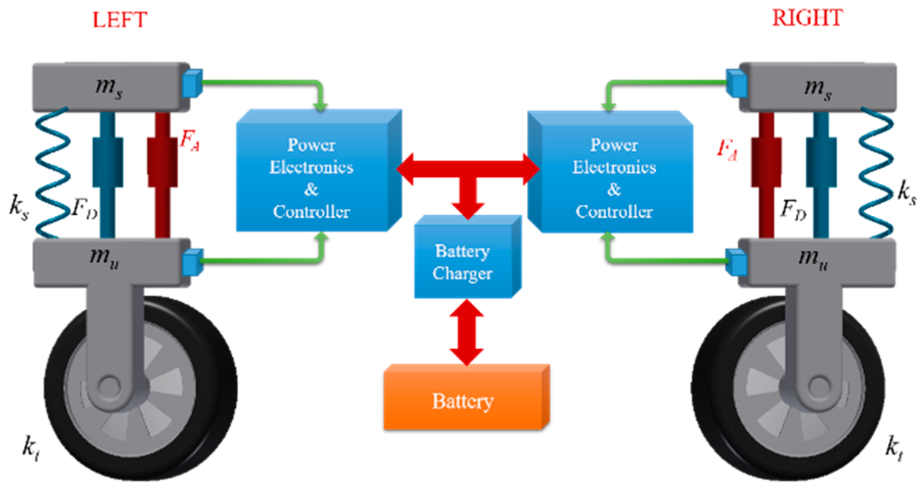
Figure 1. Configuration of energy-harvesting suspension.
Energies 14 02552 g001
Figure 2. Proposed an energy-harvesting shock absorber: (a) Design overview of linear electromagnetic generator; (b) One pole pitch.
Energies 14 02552 g002
Figure 3. Flow chart of P&O MPPT algorithm.
Energies 14 02552 g003
Figure 4. Overall structure of an active power converter using the MPPT algorithm.
Energies 14 02552 g004
Figure 5. Simulation result of current variation under discrete torque (a) proposed step size (b) fixed step size.
Energies 14 02552 g005
Figure 6. Simulation result using the P&O MPPT method with the proposed step size.
Energies 14 02552 g006
Figure 7. Overall linear generator assembly components and final prototype: (a) stator assembly; (b) mover assembly; (c) final prototype.
Energies 14 02552 g007
Figure 8. Overall power converter final prototype: (a) 3D model; (b) power converter final prototype.
Energies 14 02552 g008
Figure 9. Experimental test setup.
Energies 14 02552 g009
Figure 10. Linear generator and power converter output characteristic waveform by vibration speed: (a) 0.1 m/s; (b) 0.15 m/s; (c) 0.2 m/s; (d) 0.25 m/s.
Energies 14 02552 g010aEnergies 14 02552 g010b
Table 1. Designed power converter parameters.
ParameterValue
DC link power P D C _ l i n k 100 W
Operation frequency of generator f r s 10 Hz
Nominal DC link voltage v n o m _ D C 100 V
Voltage ripple on DC link Δ v D C 5 V
Input voltage of buck converter vin100 V
Output voltage of buck converter vout48 V
Switching frequency fsw40 kHz
Inductor current ripple ratio LIR0.3
Output max overshoot voltage vov,1 V
Inductor max current IOUT,max4 A
Load resistance R56 Ω
Inductor peak current i p k 4.62 A
DC link capacitance C D C _ l i n k 501 μF
Buck converter inductance L s y n _ b u c k 520 μH
Buck converter capacitance C s y n _ b u c k 114 μF
Table 2. Simulation result of power and efficiency using the proposed algorithm.
SectionMechanical PowerRectifier Power η r e c t i f i e r Battery Power η M P P T
(1)59.6 W55.5 W93.1%54 W90.6%
(2)42.6 W39.7 W93.2%38.3 W89.9%
(3)80.3 W73.9 W92%72.7 W90.5%
(4)86.6 W79.8 W92.1%78.2 W90.3%
Table 3. Average power and efficiency of machine and converter experiments.
Vibration SpeedAverage Machine PowerAverage Converter Power η p o w e r   c o n v e r t e r
0.1 m/s13.1 W11.8 W89.8%
0.15 m/s28.5 W26.4 W92.7%
0.2 m/s43.5 W42.9 W93.2%
0.25 m/s68.6 W62.8 W91.6%
Publisher’s Note: MDPI stays neutral with regard to jurisdictional claims in published maps and institutional affiliations.