Article

Performance of Reconfigurable Antenna Fabricated on Flexible and Nonflexible Materials for Band Switching Applications

by
B. R. Sanjeeva Reddy
1,
Naresh K. Darimireddy
2,*,
Chan-Wang Park
2 and
Abdellah Chehri
3,*
1
BV Raju Institute of Technology, Medak 502313, India
2
Department of MCSE, University of Quebec, Rimouski, QC G5L 3A1, Canada
3
Department of Applied Sciences, University of Quebec, Chicoutimi, QC G7H 2B1, Canada
*
Authors to whom correspondence should be addressed.
Energies 2021, 14(9), 2553; https://doi.org/10.3390/en14092553
Submission received: 20 March 2021 / Revised: 22 April 2021 / Accepted: 26 April 2021 / Published: 29 April 2021
(This article belongs to the Special Issue Wireless Communication Technologies in 5G and 6G)

Abstract

:
In this article, a novel frequency slot-based switchable antenna fabricated on flexible and nonflexible materials is presented for suitable reconfigurable radiations of Bluetooth, WiMAX, and upper WLAN applications. Initially, the performance of this structure was simulated using a CSTTM simulator and evaluated experimentally using a nonflexible FR4 structure. The same antenna was implemented on a flexible (jean) substrate with a relative permittivity of 1.7. The proposed textile antenna prototypes were fabricated by optimal dimensions of an E-shaped slot with a variation on the shape of the ground layer, integrated using a crossed T-shaped strip with ON/OFF switchable state operations. The proposed antenna prototype is compact (20 × 20 mm2), providing switchable radiations with tri bands, has frequencies ranged at 2.36–2.5 GHz for Bluetooth, 3.51–3.79 GHz and 5.47–5.98 GHz for the distinct bands of WiMAX and WLAN, respectively, as well as part of UWB operations.

1. Introduction

With the advent of a new class of communication systems, frequency reconfigurable antennas have generated a lot of attention, as they are capable of radiating more than one pattern at different frequencies and multiband services [1]. Several antennas that have reconfigurable frequency characteristics have been developed. The method of stacked reconfigurable patch antennas is designed for different frequencies in a single structure, and then switches are used to control the operating frequency. Jamlos et al. [2] proposed reconfigurable quadratic slots operating at noncommercial WiMAX and 4G applications. However, the structure is potentially operating at the RF front end for the 2.3 GHz band. Typically, switches are used to change the electrical length of rectangular slot ring antennas, as proposed by Gupta et al. [3]. Interestingly, tuning the structure works well at low frequencies, and switches limit their use as the frequency increases. For operation at higher frequencies, researchers proposed using RF MEMS switches rather than diodes to change the antenna length or size. Switches are electronically placed in the form of a planar array, which operates fairly at a frequency less than 2 GHz, as proposed by Pringle et al. [4].
Research on flexible textile antennas has been reported in the open literature on-body and off-body communication applications, including materials used for textile antennas [5,6], design techniques, and modeling aspects of planar wearable antennas [7,8,9], which were studied comprehensively. Switchable antennas are highly recommended and are considered attractive due to their use in integrated circuits and applications. To achieve dual-band textile reconfigurable antennas, several techniques were used, such as cutting slots [10,11,12,13] where metal parts are implanted on the fabric to create additional resonance, although degrading the performance due to an uncontrolled SAR value and bending conditions. A flexible and compact antenna operating at 2.45 GHz and 5.25 GHz bands can be fabricated on a blue jean substrate, as discussed by Farooq et al. [14]. A textile antenna operating at a 5.8 GHz WiMAX band produces a low SAR value and a high gain, as implemented by Petr et al. [15]. However, it was found that due to switching conditions, the compactness and gain enhancement with a low SAR can further be improved when compared to the existing designs.
In this paper, a traditional switching technique of using a PIN diode is proposed to imitate the switch through simulation and experimental environments [16]. Simulations are carried out with both classified modes covering the absence and presence of the metal pad operated in OFF and ON states. Progressive simulated and measured return loss curves considering the PIN diode bias conditions, the reconfigurable operation is found from ON/OFF modes. When the diode is operated in OFF mode, the antenna covered frequency only for the WLAN range. If the diode is in the ON state, the simulated operating frequencies of the textile antenna are 2.5 GHz, 3.6 GHz, and 5.3 GHz.”. However, the measurement of prototypes needs to be validated manually to differentiate the performance. The same antenna prototype is implemented in a different dielectric textile fabric substrate value of 1.7 and compared with the metrics found from a nonflexible FR4 substrate.

2. Proposed Antenna Configuration and Analysis

2.1. Demonstration and Testing of Antenna

A compact square-shaped antenna configuration with its proposed design parameters on either side of a nonflexible substrate of FR4 with a thickness of 0.8 mm and a dielectric constant of 4.4 is shown in Figure 1a. The proposed structure is modified with an embedded E-shaped slot on the square radiating patch in the top layer, fed with a modified feed-line. It was found that the separation of two narrow slits (with W7 = 1.1 mm) is placed symmetrically with respect to the patch’s centerline. Along the patch’s centerline, a tuned line feed from the bottom edge of a patch can be located for good excitation of the proposed antenna over an enhanced bandwidth. By embedding a T-shaped shaped slit on the back layer of the copper-clad as shown in Figure 1b, the excited patch surface current path of TM10 mode of the T-shape slot was greatly lengthened, which effectively lowered its resonant frequency and gave the proposed design a reduced patch size for the fixed lower frequency of dual-band radiation. This cross-shaped slot acted as a defected ground structure that generated current disruption on the opposite side of the feed line and protruded rectangular patch. The inverted cross-shaped strip was connected to the protruded rectangular strip bypassed through a PIN diode.
The final design parameters with dimensions of this proposed structure’s top and bottom layer are listed in Table 1. Simulation studies through trial-and-error-based iterations on antenna structures were used to obtain the optimized final design and also optimized line feed utilizing the aid of the CST Microwave Studio EM simulator. The design began by choosing a conventional antenna that comprises a modified rectangular-shaped slot on the ground layer. This slot can generate a resonant frequency close to 3.5 GHz. A stick-out modified rectangular strip was fabricated on the ground layer to advance the operating frequency towards higher GHz frequencies. Hence, the wearable antenna can generate a band of frequencies close to 5.65 GHz. The etching of the line feed was performed symmetrically to match both flexible and nonflexible design prototypes. Further, the ground plane was etched with two parallel cross-shaped slots to achieve better impedance bandwidth.
With the modified E-shaped slot embedded on the square patch, dual resonant frequencies were generated at 3.8 GHz and 5.6 GHz. The final iterative shape of the rectangle element was turned into inverted cross-shaped cut on the ground plane that was formed as the final iterative design, where the prototype exhibited tri-bands operated at WiMAX, Bluetooth, and upper WLAN systems respectively at 2.45 GHz, 3.63 GHz, and 5.64 GHz. Table 1 represents the optimized dimensions of the proposed antenna and the crossbar slot (in mm) with ON/OFF modes, as mentioned below.
The parametric study in the next section deals with the change in the antenna characteristics with reference to the diode operation transforming itself to operate in tri bands from a single band with the optimized structure design. Moreover, the structure can provide a reconfigurability feature in making the parasitic elements equivalent to tri-band operation and the high impedance bandwidth with a compromising value of gain at the respective resonating bands. Further, referring to the current work, a wearable antenna supporting a reconfigurability feature is designed and simulated on a flexible jean substrate to find the dual resonant bands with an enhanced gain. The specific absorption rate (SAR) value for both dual-band frequencies is also evaluated from the simulated studies.

2.2. Effect of Different Dielectric Constants

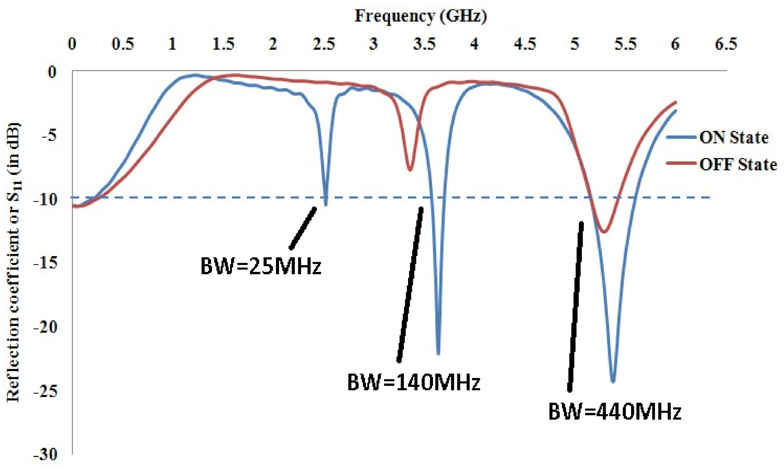
This section discusses the implementation of a reconfigurable antenna for both the nonflexible FR4 substrate and the flexible jean substrate. Numerical studies have been performed to optimize the design and parameters and to obtain the final dimensions. The simulated S11 curve with optimized values of the length parameter and the position of the line feed for the FR4 substrate is plotted in Figure 2. Thus, when the length of the left slot increases, the response gradually resonates at 2.6 GHz. The alternation of the width of the slot in the ON and OFF states of the diode was shown as a key parameter in adjusting the WLAN resonance. Moreover, by varying the parameter length by a step of 0.5 mm (from 6 to 7 mm) in the OFF mode of the diode, the bandwidth can be tuned to the WLAN range. The center frequency was adjusted by a variation in the length and a determination of the appropriate location from 1 to 3 mm. It was found from the response curve that the modeled antenna operated at dual bands and at tri bands respectively in the OFF mode and on mode when implanted with the FR4 substrate. The model generated tri-band resonating frequencies that are appropriate for the latest applications such as Bluetooth, WiMAX, and a portion of UWB operation.
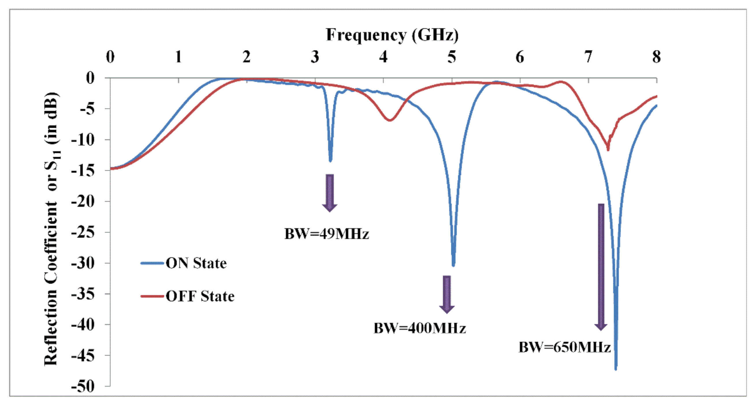
A similar analysis was considered for a different dielectric constant of 1.7 for the jean fabric to obtain a tri-band operation. Figure 3 shows the return loss characteristic curve for the ON and OFF states when the antenna was implanted on flexible jean substrate. The dual bands generated for the off mode were not tuned to the appropriate application due to the reason that the thickness was very small for the wearable cloth. During the on mode, the obtained frequencies were closer, covering the latest 5G wireless applications.

3. Outcomes and Discussion

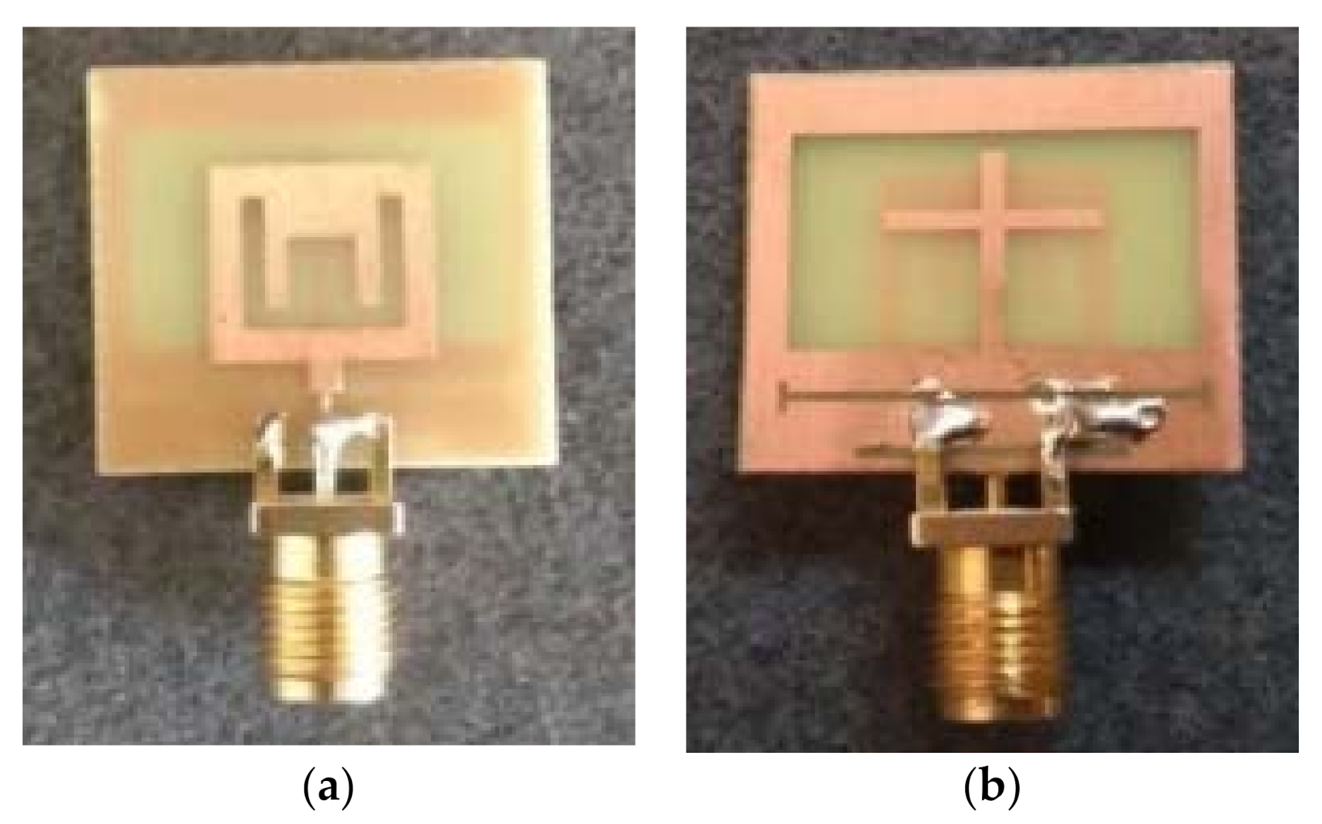
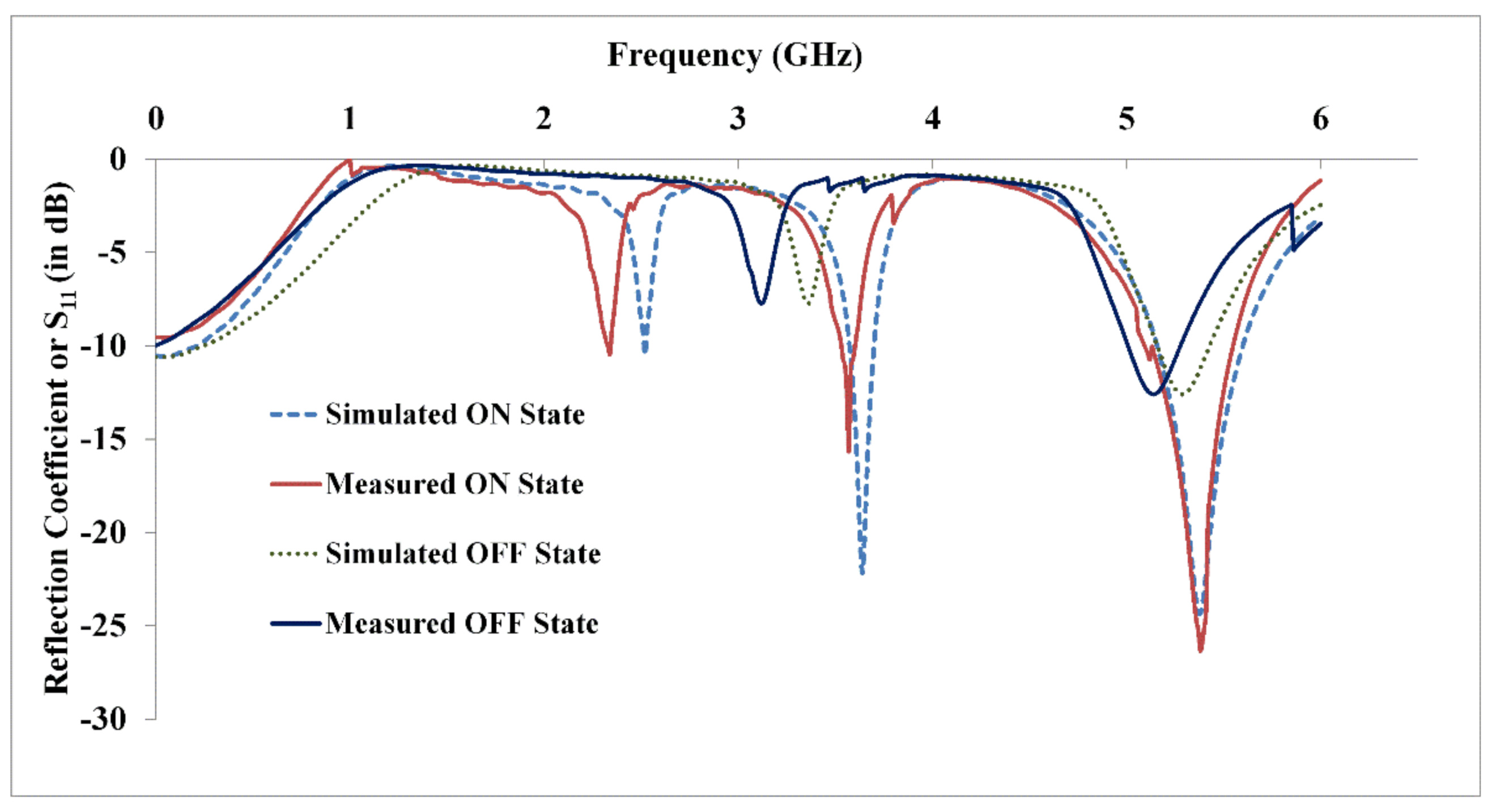
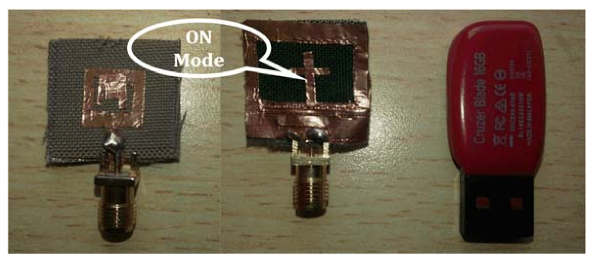
In this section, the proposed configuration with its final optimized dimensions is fabricated, measured, and compared with simulated values. This means that the ON and OFF states of the switch (PIN diode) are simulated in the presence or absence of a metal pad, respectively. The frequency switching is possible in two states. When it is in the off state, the antenna covers only the WLAN range of 5.20–5.43 GHz. Resonant values generated with the proposed textile antenna are below the −10 dB threshold line, indicating that the antenna parameters approached better metrics such as enhanced bandwidth and low VSWR. An optimized fabricated model was obtained, which has significance and was claimed to be a better reconfigurable textile antenna. When it is in the ON state, it was observed that the antenna resonates in the frequency ranges of 2.51–2.535 GHz, 3.51–3.7 GHz, and 5.15–5.59 GHz for Bluetooth, a part of the Wi-MAX, and upper WLAN applications, respectively. The antenna offers an efficiency higher than 70% in the bands of 2.52 GHz, 3.63 GHz, and 5.37 GHz during the ON mode; during the off mode at 5.5 GHz, it drops to 40% in the higher resonance band. Figure 4 shows the fabricated top view and bottom views of reconfigurable slot antenna indicated in the ON state, which is experimentally tested using the vector network analyzer.
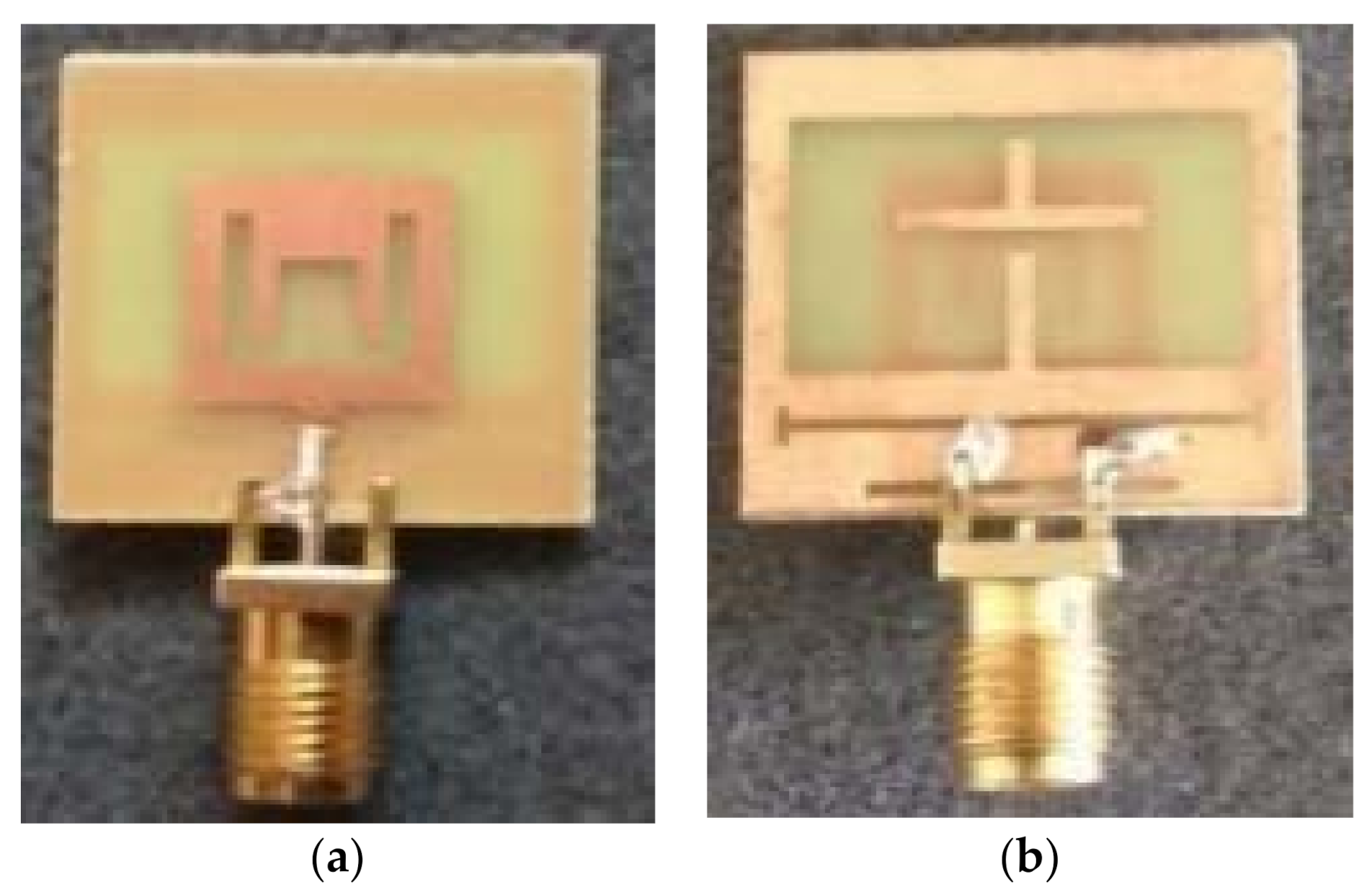
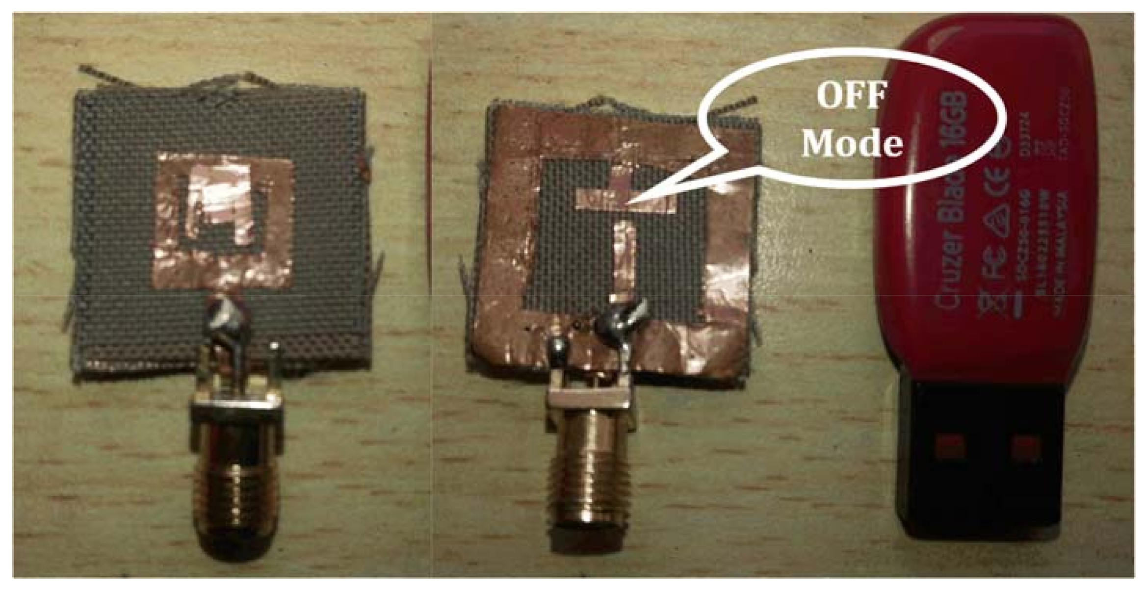
The fabricated antenna with its top and bottom views indicated in the OFF state is as shown in Figure 5. The measured and simulated return loss response curves for both the dielectric constants in the ON and OFF states are represented in Figure 6.
During the process of fabrication, there are two different approaches opted. The first one is to stitch the metal threading on either side of the jean substrate, making the structure semiconductive. The second one is to apply the copper cladding tape with a thickness of 0.016 mm placed on either side; this has the advantage of fixing the line feed ported to the strip line edged from the patch structure.
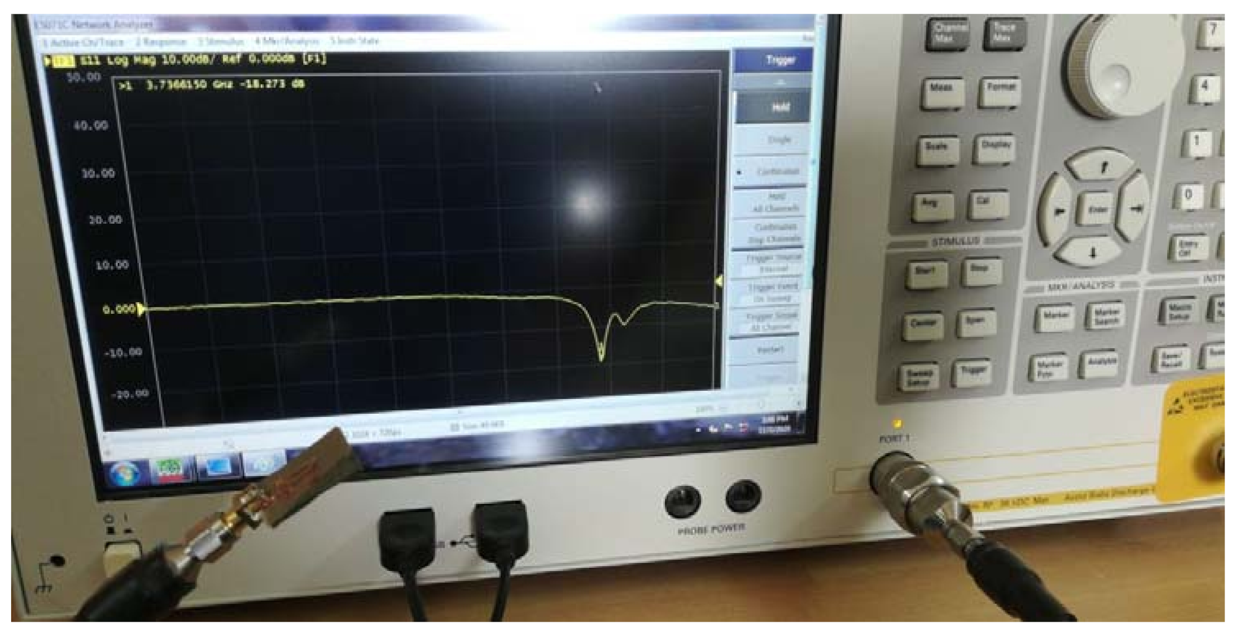
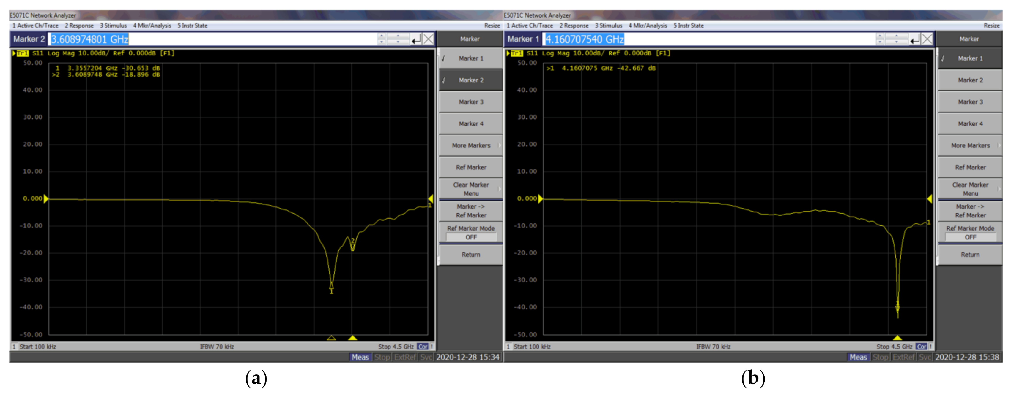
Figure 7 and Figure 8 show the fabricated top view and bottom views of the reconfigurable slot antenna with flexible jean substrate indicated in the ON and OFF states, respectively. The same is experimentally verified using the E5071C Keysight vector network analyzer. Figure 9 shows the experimental setup, and Figure 10 presents the measured S11 parameters in the ON and OFF modes, respectively. The anomalies between the measured and simulated results are due to in-house manufacturing and soldering alignments.
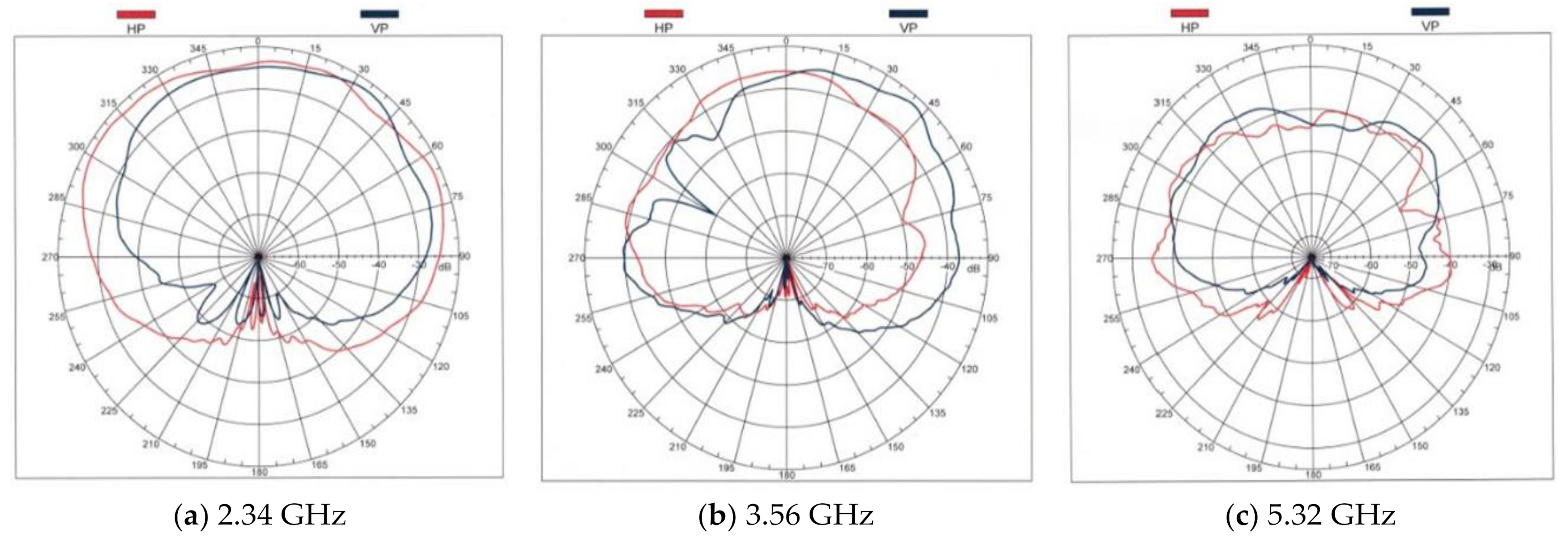
Table 2 displays the comparison of antenna characteristics of the proposed antenna in ON/OFF states. It clearly shows that it resonated only at a single band when the diode was in the OFF state and that it transformed itself into a tri-band operating antenna when the diode was in the ON state. An impedance bandwidth of 440 MHz was obtained at the higher resonant frequency of 5.41 GHz. The VSWR value is less than 2 for all the resonant frequencies. Gain values of 0.6, 1, and 2.07 dBi for the operating tri bands 2.53, 3.64, and 5.41 were obtained. Figure 11 gives the radiation patterns for the tri bands; in the E-plane, phi = 90° was provided, and insufficient radiation was obtained at a higher band as the size of the antenna was reduced. The proposed antenna was linearly polarized at all the obtained bands, and a moderate gain of ~1.5 dBi was obtained, covering the applications such as WiMAX, Wi-Fi, and WLAN.
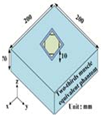
Table 3 lists different antenna parameters of the proposed antenna with different dielectric constants during the ON and OFF operation of the proposed antenna with the existing designs in the literature. The reconfigurability operation for the textile antenna operating in different states is presented. It was found that the SAR values were moderate at higher frequencies and that they fell to a lower value at a low frequency. The jean substrate in the off state shows that it resonated at the single band with a high SAR value of 16 W/kg.
A significant gain value of ~2.5 dBi is obtained in the ON state mode of the textile antenna. A tri-band operation with an average of 2 dBi was found for the FR4 dielectric constant. In this work, the measured values of the reflection coefficient and VSWR were found using the near field in the open environment with the help of a vector network analyzer.
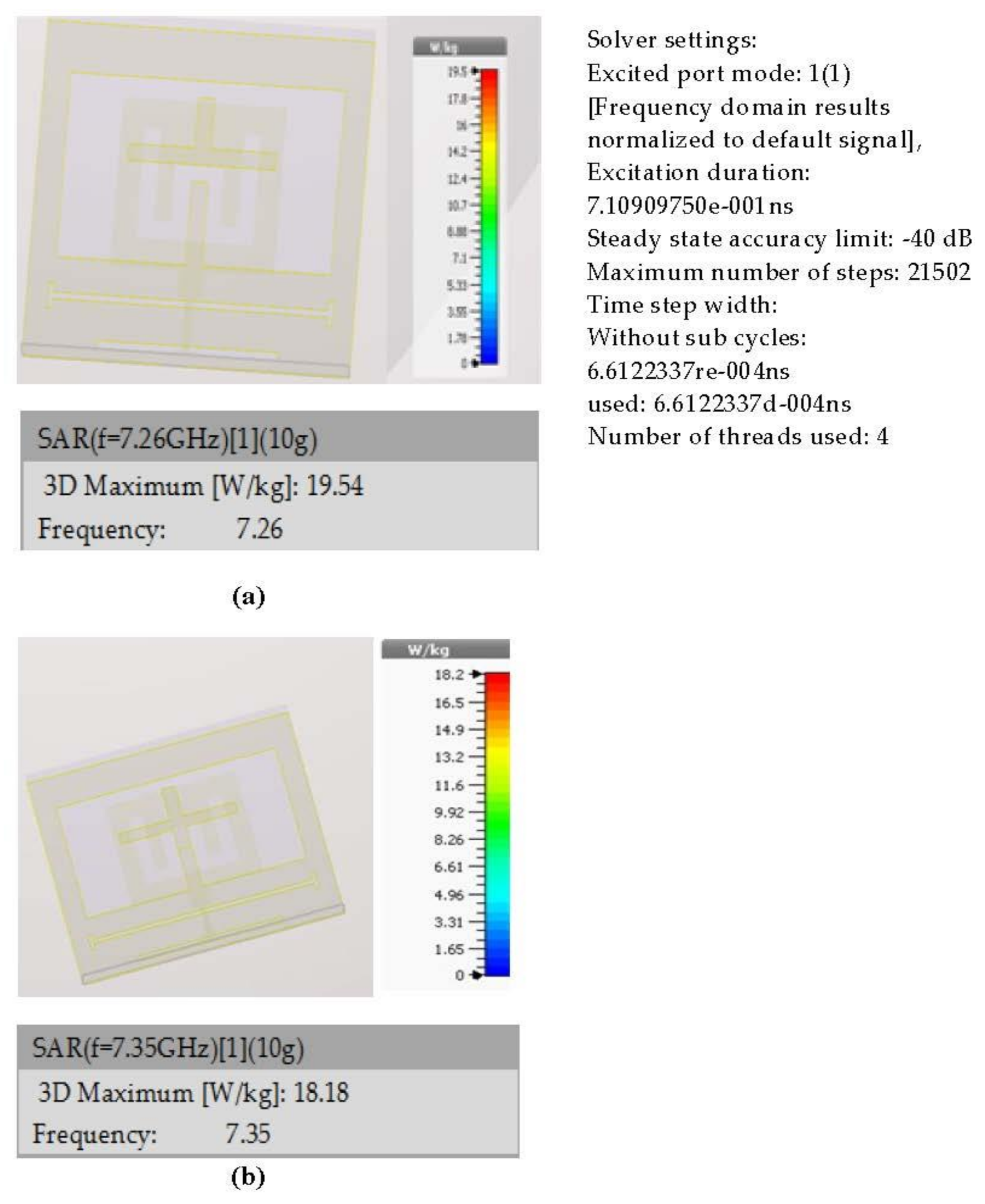
The SAR simulated response for an operating frequency of 7.35 GHz is represented in Figure 12, and it shows that the SAR value denoted on the scale is 18.2 W/Kg. This SAR value was maintained at low since the textile antenna is worn on a conductive body. The proposed work in Table 3 shows that the SAR held a low value at a frequency of 3.22 GHz for the flexible jean substrate. The material thickness, conductivity, operating frequency range, and resonant behavior were carefully chosen to be distinct in order for us to understand the resulting SAR better. SAR is a measure of power absorbed per unit mass, e.g., in the human body tissue.

4. Conclusions

In this article, a novel compact reconfigurable antenna with two switching states was proposed for frequency reconfigurability between WLAN at 5.04–6.13 GHz and a tri-band consisting of Bluetooth at 2.36–2.5 GHz, WiMAX at 3.51–3.79 GHz, and WLAN at 5.47–5.98 GHz ranges with desired omnidirectional radiation patterns at an H-plane. Antenna characteristics were also differentiated for both nonflexible FR4 and flexible jean substrate material. The frequency was switched by a PIN diode, which was inserted in an inverted T-shaped strip to a protruded strip in the ground layer. The SAR value for the implemented textile antenna for both ON/OFF states was also investigated. The experimental values agreed with the simulation results, showing that the proposed antenna can be a good candidate for modern multiband systems and military wireless applications.

Author Contributions

Conceptualization, B.R.S.R.; Data curation, N.K.D.; Funding acquisition, A.C.; Methodology, N.K.D.; Supervision, N.K.D., C.-W.P. and A.C.; Writing—original draft, B.R.S.R.; Writing—review & editing, N.K.D. and C.-W.P. All authors have read and agreed to the published version of the manuscript.

Funding

This research received no external funding.

Acknowledgments

The authors would like to acknowledge the support of SERB-DST under File No. ECR/2016/000585 in utilizing the resources of the Advanced Communication Laboratory (ACL) under the Department of ECE. The authors are also greatly indebted to the head of the department, I.A. Pasha and the team of ACL for their encouragement to carry out this work.

Conflicts of Interest

The authors declare no conflict of interest and the funders had no role in the design of the study, in the collection, analyses, or interpretation of data, in the writing of the manuscript, or in the decision to publish the results.

References

  1. Bernhard, J.T. Reconfigurable antennas and apertures: State-of-the-art and future outlook. In Proceedings of the SPIE Conference Smart Electronics, MEMS, BioMEMS, and Nanotechnology, San Diego, CA, USA, 22 July 2003; Volume 5055, pp. 1–9. [Google Scholar]
  2. Jamlos, M.F.; Rahman, T.A.; Kamarudin, M.R.; Malek, M.F.; Jusoh, M. The effects of air stacked on reconfigurable quadratic slots antenna for WiMAX and 4G applications. Microw. Opt. Technol. Lett. 2012, 54, 2139–2144. [Google Scholar] [CrossRef]
  3. Gupta, K.C.; Li, J.; Ramadoss, R.; Wang, C. Design of frequency-reconfigurable slot ring antennas. In Proceedings of the IEEE/URSI International Symposium Antennas and Propagation, Salt Lake City, UT, USA, 16–21 July 2000; Volume 1, p. 326. [Google Scholar]
  4. Pringle, L.; Harms, P.; Blalock, S.; Kiesel, G.; Kuster, E.; Friederich, P.; Prado, R.; Morris, J.; Smith, G. A reconfigurable aperture antenna based on switched links between electrically small metallic patches. IEEE Trans. Antennas Propag. 2004, 52, 1434–1445. [Google Scholar] [CrossRef]
  5. Salvado, R.; Loss, C.; Gonçalves, R.; Pinho, P. Textile materials for the design of wearable antennas: A survey. Sensors 2012, 12, 15841–15857. [Google Scholar] [CrossRef]
  6. Ali, S.M.; Sovuthy, C.; Imran, M.A.; Socheatra, S.; Abbasi, Q.H.; Abidin, Z.Z. Recent advances of wearable antennas in materials, fabrication methods, designs, and their applications: State-of-the-art. Micromachines 2020, 11, 888. [Google Scholar] [CrossRef]
  7. Del-Rio-Ruiz, R.; Lopez-Garde, J.-M.; Legarda, J. Planar textile off-body communication antennas: A survey. Electronics 2019, 8, 714. [Google Scholar] [CrossRef] [Green Version]
  8. Saraereh, O.A.; Khan, I.; Lee, B.M.; Al-Bayati, A. Modeling, and analysis of wearable antennas. Electronics 2019, 8, 7. [Google Scholar] [CrossRef] [Green Version]
  9. Kirtania, S.G.; Elger, A.W.; Hasan, M.R.; Wisniewska, A.; Sekhar, K.; Karacolak, T.; Sekhar, P.K. Flexible antennas: A review. Micromachines 2020, 11, 847. [Google Scholar] [CrossRef] [PubMed]
  10. Pazin, L.; Leviatan, Y. Reconfigurable slot antenna for switchable multiband operation in a wide frequency range. IEEE Antennas Wirel. Propag. Lett. 2013, 12, 329–332. [Google Scholar] [CrossRef]
  11. Salleh, S.M.; Jusoh, M.; Ismail, A.H.; Kamarudin, M.R.; Ahmad, M.I.; Sabapathy, T. Reconfigurable frequency textile antenna with circular polarization using slotted technique. Appl. Mech. Mater. 2015, 781, 81–84. [Google Scholar] [CrossRef]
  12. Fakharian, M.; Rezaei, P.; Orouji, A. Reconfigurable multiband extended U-slot antenna with switchable polarization for wireless applications. IEEE Antennas Propag. Mag. 2015, 57, 194–202. [Google Scholar] [CrossRef]
  13. Lee, H.; Choi, J. A polarization reconfigurable textile patch antenna for wearable IoT applications. In Proceedings of the 2017 International Symposium on Antennas and Propagation (ISAP), Phuket, Thailand, 30 October–2 November 2017. [Google Scholar]
  14. Tahir, F.A.; Javed, A. A compact dual-band frequency-reconfigurable textile antenna for wearable applications. Microw. Opt. Technol. Lett. 2015, 57, 2251–2257. [Google Scholar] [CrossRef]
  15. Vasina, P.; Lacik, J. Textile linear polarization reconfigurable ring slot antenna for 5.8 GHz band. In Proceedings of the 2017 Conference on Microwave Techniques (COMITE), Brno, Czech Republic, 20–21 April 2017. [Google Scholar]
  16. Garcia-Cruz, X.; Sergiyenko, O.; Tyrsa, V.; Rivas-Lopez, M.; Hernandez-Balbuena, D.; Rodriguez-Quiñonez, J.; Basaca-Preciado, L.; Mercorelli, P. Optimization of 3D laser scanning speed by use of combined variable step. Opt. Lasers Eng. 2014, 54, 141–151. [Google Scholar] [CrossRef]
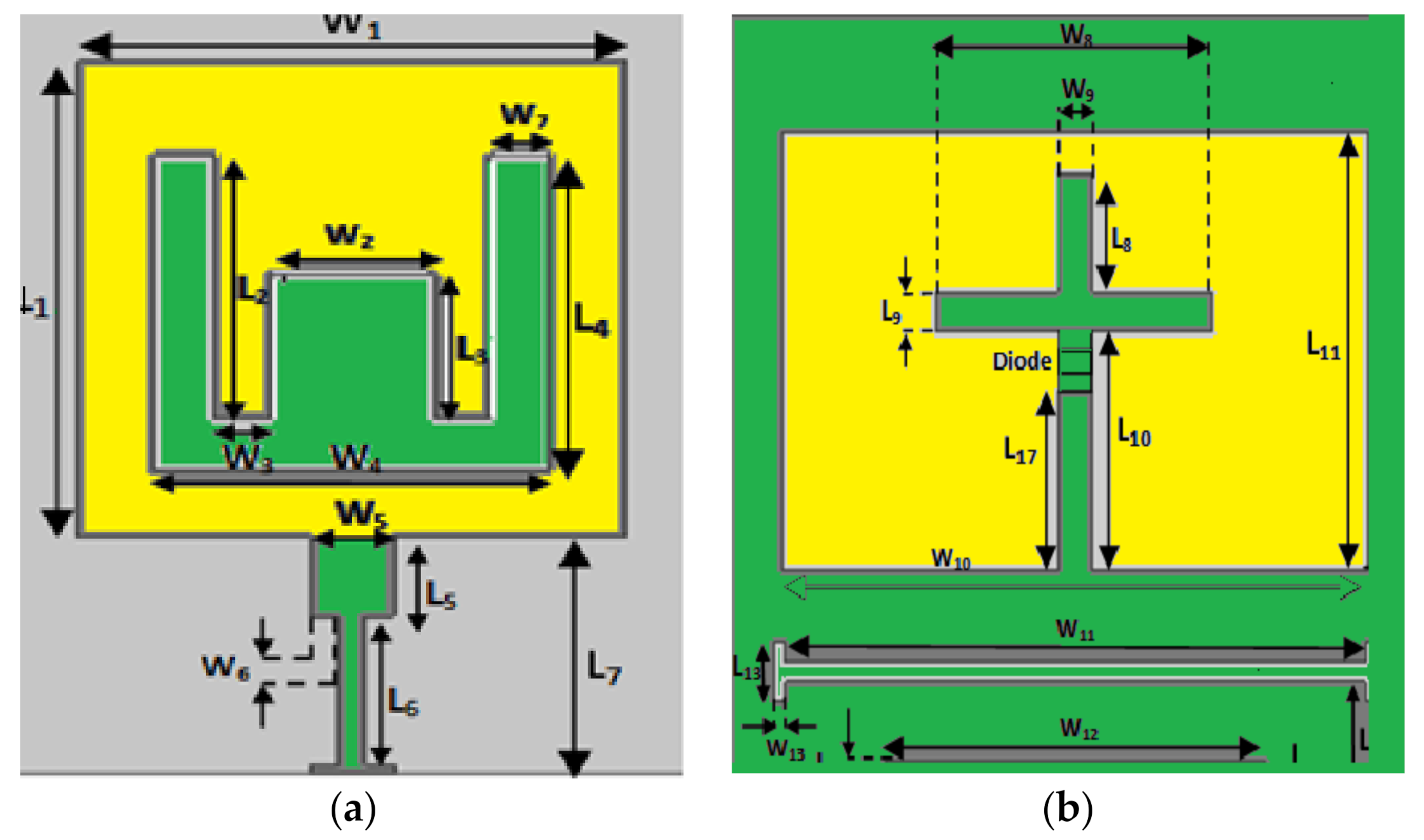
Figure 1. Proposed antenna configuration: (a) top layer; (b) bottom layer.
Energies 14 02553 g001
Figure 2. Simulated return loss response for ON/OFF states on the FR4 substrate.
Energies 14 02553 g002
Figure 3. Simulated return loss response for ON/OFF states on the flexible jean substrate.
Energies 14 02553 g003
Figure 4. Photograph of the fabricated (nonflexible FR4 substrate) reconfigurable antenna with DC biased in the on state: (a) top layer; (b) bottom layer.
Energies 14 02553 g004
Figure 5. The photograph of the fabricated (nonflexible FR4 substrate) reconfigurable antenna with DC biased in the off state: (a) top layer; (b) bottom layer.
Energies 14 02553 g005
Figure 6. Measured and simulated S11 response of the nonflexible (FR4) substrate.
Energies 14 02553 g006
Figure 7. Photograph of the fabricated (on flexible jean substrate) top and bottom layers of reconfigurable antenna with DC biased in the ON state.
Energies 14 02553 g007
Figure 8. Photograph of the fabricated (on flexible jean substrate) top and bottom layers of reconfigurable slot antenna with DC biased in OFF state.
Energies 14 02553 g008
Figure 9. Experimental verification of the proposed flexible reconfigurable slot antenna for return loss response using VNA.
Energies 14 02553 g009
Figure 10. Measured return loss response of the flexible reconfigurable slot antenna in (a) on and (b) off modes.
Energies 14 02553 g010
Figure 11. Measured radiation patterns of the proposed antenna (represented in the xy E-plane).
Energies 14 02553 g011
Figure 12. Simulated SAR response scale when diode is in (a) OFF state at 7.26 GHz and (b) ON state at 7.35 GHz (flexible jean substrate).
Energies 14 02553 g012
Table 1. Optimized geometrical dimensions of the proposed antenna.
ParametermmParametermm
Width (W)20L110
W110L25.5
W23L33
W31L46.6
W47.2L51.7
W51.5L63.1
W60.5L75
W71.1L83
W88L91
W91L106
W1017L1111
W1116.8L120.5
W1211L131.5
W130.3L140.7
L153.2L166
Length (L)20L174.5
Table 2. Characteristics comparison of different dielectrics with ON/OFF states.
Switching StatesDielectric
Constant
Resonant
Frequencies (GHz)
VSWRImpedance Bandwidth
(MHz)
Gain (dBi)# SAR (W/Kg)
ON State4.4 (FR4)2.531.8250.6* NA
3.641.181401
5.411.034402.07
1.7 (jean) 3.221.42492.45.9
4.991.24002.911.1
7.351.25650418.2
OFF State4.4 (FR4)5.291.62801.81* NA
1.7 (jean)7.261.68901.9316
# SAR, specific absorption rate; * NA, not applicable.
Table 3. Comparison of parameters for the proposed antenna with existing models.
Ref.Freq. (GHz)10-dB * RLBW
(MHz)
Gain (dBi)SAR
(W/Kg)
Structure
[11]
On/off switching with PIN diodes
1.575
2.45
60
250
-
-
-
-
Energies 14 02553 i001
[12]
On/off switch for U slot
2.4
5.8
320
500
3.4
5.8
-
-
Energies 14 02553 i002
[13]
Reconfigurable textile antenna
2.4583.55.9616.2 Energies 14 02553 i003
[14]
Textile-based reconfigurable antenna
2.45
5.25
130
150
3.17
3.55
Low Energies 14 02553 i004
[15]
Ring slot textile antenna
5.83246.5–7.511.3 Energies 14 02553 i005
Proposed work (FR4)ON State
2.34
3.56
5.32
40
80
460
0.8
1.2
2
NA
OFF State
5.152501.79NA
Proposed work (Jeans)ON State
3.22
4.99
7.35
49
400
650
2.5
2.7
3.8
5.9
11.1
18.2
OFF State
7.2690216
* RLBW, return loss bandwidth.
Publisher’s Note: MDPI stays neutral with regard to jurisdictional claims in published maps and institutional affiliations.