1. Introduction
Brushless direct current (BLDC) motors have become popular in a wide range of applications [
1], including unmanned aerial vehicles (UAVs). The main advantages of BLDC motors are their high dynamic response, high power density, high speed and efficiency, compact structure, long life, low cost, their light weight per power unit, and low maintenance requirements due to the absence of carbon brushes. However, the usage of BLDC motors may be limited by the maximum applied voltage, by the available electrical power, and by the availability of suitable electronic speed controllers. BLDC motors with voltage levels in the range of 6 to 24 V are the most common [
2]; however, there is a trend towards increasing voltage levels, and thus towards reducing the current while keeping the required power level.
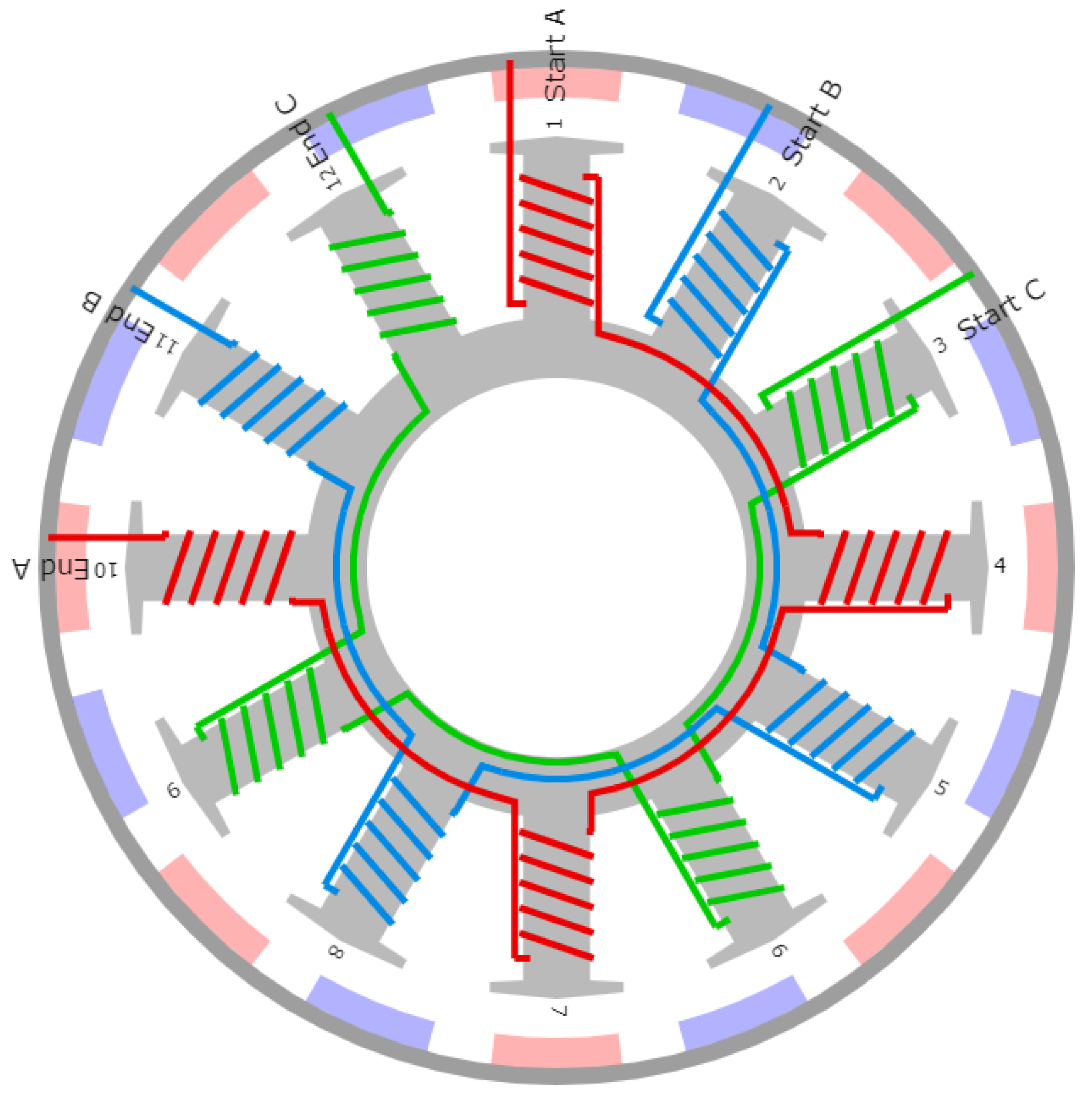
A typical BLDC motor structure uses a delta winding interconnection and consists of 12 stator slots and 16 rotor magnets, although the numbers, and the ratio of the poles and magnets, can vary. An example of a typical structure with winding animation is depicted in
Figure 1, which is an output of the online BLDC winding scheme calculator [
3].
According to the basic principles of an electric motor, the output mechanical power P can be evaluated as: where M represents the torque in Nm, is the angular velocity in rad/s, and n stands for the rotational speed in revolutions per minute (RPM).
The limits of the torque are related to the limits of the magnetic flux, to the diameter of the rotor and/or its volume. In this area, attention is currently being paid to shape optimization methods for the inner part of the motor, e.g., in terms of stator slots [
4], magnetic equivalent circuit (MEC) models [
5,
6], and the losses in the ferrite cores and steel lamination BLDC motors [
7]. In addition, research is focused on the increase in torque with a radial multilayer structure, e.g., a novel five-phase double-stator BLDC motor [
8].
For its operation, the BLDC motor uses an Electronic Speed Controller (ESC), which provides an electrical commutating mechanism [
9] via a closed-loop current control system. The feedback current of three-phase windings can be obtained either through direct measurements with current sensors placed in each phase, or through an estimate based on a single current sensor placed in a DC-link. A single-shunt resistor placed in a DC-link is the most inexpensive, the most reliable, and the simplest current measurement method available at the present time. It can be used with either a bipolar or a unipolar PWM control method [
10]. The DC-link corresponds to a direct measure of the back electromotive force (EMF), which is typically trapezoidal in shape, coming from a stator winding that is wound in a trapezoidal fashion. To achieve the best performance, the drive current should match the back EMF waveform as closely as possible. BLDC motors should therefore be driven with trapezoidal waveforms, which further leads to simpler controller implementation [
11]. However, the back EMF of BLDC motors are not truly trapezoidal in shape. The shape is sinusoidal rather than truly trapezoidal, so BLDC motors can use both trapezoidal and sinusoidal commutations.
Back EMF zero-crossing detection is the most mature and most widely used rotor position signal detection method [
12]; however, this detection method has inherent imperfections that can be observed in static or low-speed conditions [
13]. In these cases, the electrical signal that is received becomes zero or has a noise-comparable amplitude, and detection therefore becomes inaccurate.
For this reason, the rotor position cannot be determined precisely. Potential errors in position determination are studied in [
14]. This leads to the need for an initial rotor angular motion in open-control-loop mode for the ESC to detect adequate synchronizing pulses as the output of EMF zero-crossing detection. If the output shaft is loaded within this initial stage, the BLDC motor cannot establish rotation due to the high initial torque requirements. In practice, the output shaft can be loaded when pulses are received.
Conventional inverters built into BLDC motor controllers include 6 power switches utilizing a direct phase current control PWM method. Attempts have been made to optimize the control, e.g., via the design of a four-switch-three-phase inverter BLDC drive [
13,
15], which reduces the current ripple with a hysteresis current control. Other solutions employ multilevel inverters [
16] or single-ended primary inductance converters [
17], which optimize power factor correction and total harmonic distortion in stator currents, and thus provide a smoother voltage level and constant electromagnetic torque. In [
11], a hybrid PWM control is studied to optimize high-speed BLDC motor operation, and in [
18], there is an analysis of the performance of field-oriented control (FOC) using sinusoidal pulse width modulation and space vector pulse width modulation techniques.
In order to increase BLDC motor torque, there is clearly a need to increase the number of stator slots and rotor magnets. The diameter of the motor needs to be larger if a single layer is to be used. In addition, this common approach may change the transient behavior of the motor depending on its type, e.g., an inrunner configuration or outrunner configuration. In general, a heavier rotating mass and an increased radius lead to a greater moment of inertia, which degrades the dynamic characteristics of the motor. The moment of inertia is composed of the moment of the motor and of the load. Strictly speaking, in relation to the motor, it can be stated that the lower the moment of inertia of the motor, the better the dynamic behavior that can be expected, and the easier it should be to control the motor. The proposed solution is unlikely to increase the number of slots/magnets without increasing the diameter of the motor, but it uses three standard single-layer stators with their original size placed in parallel with a single three-layer rotor that is a common body of all of them. This approach increases the motor power N times for N-layer construction while keeping the moment of inertia low. In the proposed solution, N is equal to 3, but this number can be changed if required. A similar approach can be found, e.g., in the case of the switched reluctance motor, in [
19,
20,
21], where the multilayer structure supports high speed applications with higher torque and lower torque ripple in comparison with conventional switched reluctance motors.
The contribution of this paper lies in a modification of the BLDC motor structure, in which multiple stator and rotor layers are put together in parallel to increase the torque, even under low speed conditions. This structure allows the use of more interconnections with 9 windings and enables us to study their impact on the torque and on the operational efficiency. Thus, the main aim is to study the behavior of the motor based on different winding interconnection schemes, while a standard stator is utilized in a multilayer stator configuration. The proposed solution is confirmed with a motor built in-house for experimental purposes. The analyses that have been performed cannot be used to confirm the performance of the entire motor and its suitability for a real application; however, in the first stage of the research, the suitability of this solution for supporting the torque under low-speed conditions is confirmed. The motor design in the case studied here is not optimal for its final application on UAVs, where a low velocity constant Kv and high efficiency are required, since it utilizes standard components to accelerate the initial phase of the research. The motor has been tested within its design limits, i.e., in a speed range up to 3500 RPM; nevertheless, the design has served its purpose in confirming the correctness of the direction in a multilayer stator configuration and in its future applications to UAVs.
This paper is organized as follows:
Section 2 provides details about the proposed multilayer structure of the BLDC motor with its advantages when UAV applications are considered.
Section 3 gives details about the experimental setup.
Section 4 then confirms the proposed solution based on experiments performed for different winding interconnections. Conclusions are drawn in
Section 5.
2. Proposed Multilayer Solution of the BLDC Motor
The proposed multilayer outrunner BLDC motor structure uses 12 stator slots and 16 rotor magnets, placed in 3 parallel layers. The layers in the multilayer stator configuration are not in a radial direction but are along the main motor axis. This modification does not increase the overall motor diameter but only extends the size in the longitudinal direction. The proposed modification suffers from lower extra weight added, unlike in the case of BLDC motors, where the layers are placed in the radial direction or the number of stator slots in a single layer is increased. When the outrunner type of motor is used, it can be expected that most of the weight is formed by the stator. The proposed solution therefore does not extend the radius of the rotor, i.e., a rotating mass, by increasing the diameter of the stator. The winding in a single layer corresponds to the conventional order, as shown in
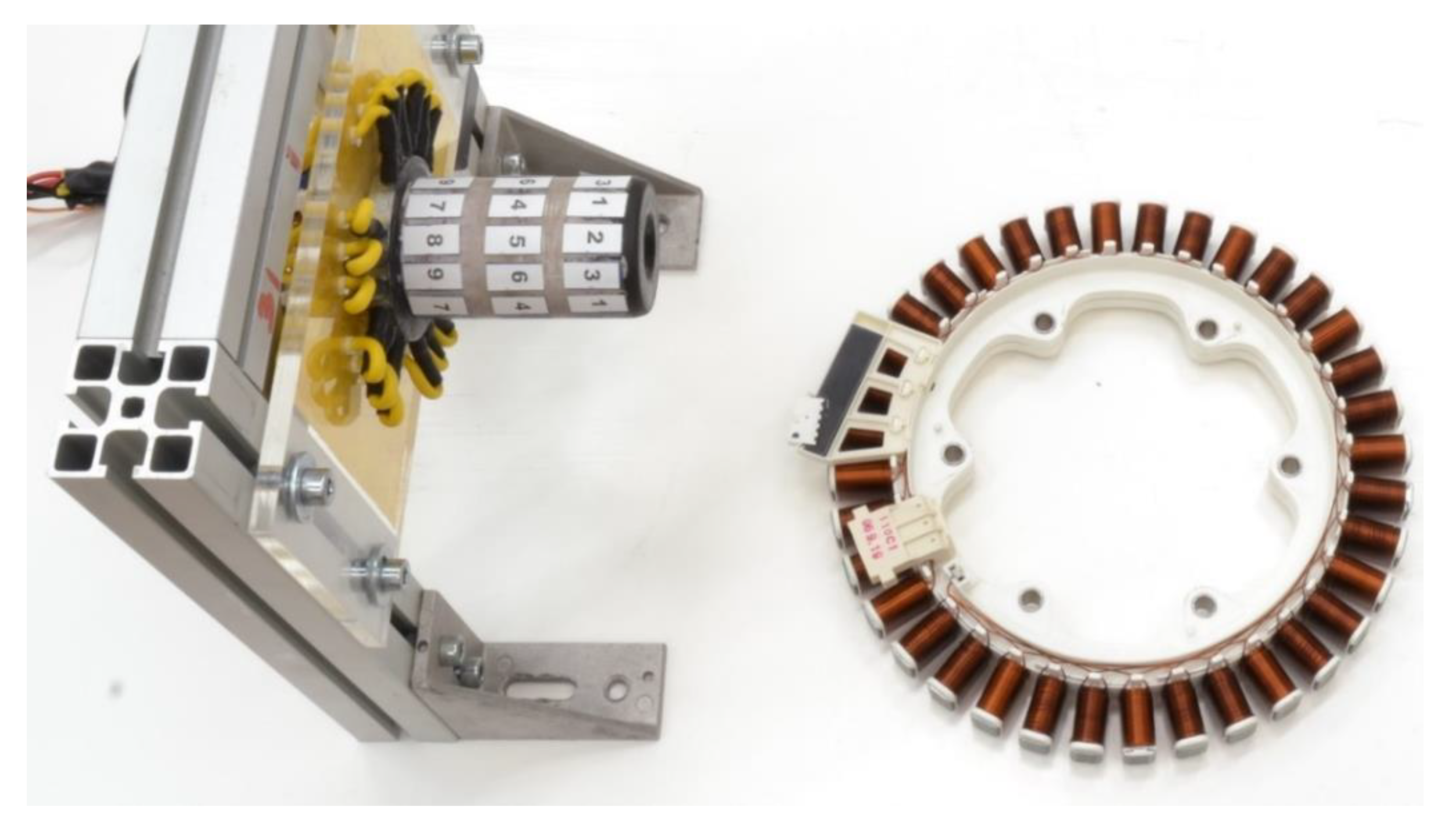
Figure 1. Since the proposed solution uses standard construction parts, its main core has been composed of three inner cores of the AXI 5320/18 GOLD LINE V2 motor [
22], shown in
Figure 2 and has been newly wound up, equipped with a rotor, and finalized. The construction layout is depicted in
Figure 3 and
Figure 4. The number of layers can even be increased to optimize the BLDC motor performance for applications where a high torque is required. The layers are isolated with a metal plate 1 mm in thickness to minimize common influences. This structure does not extend neither the diameter nor the moment of inertia, but it supports the mechanical torque of the BLDC motor. A comparison between a three-layer stator structure and a single-layer stator structure with 36 stator slots is depicted in
Figure 5.
The functional design of the proposed solution uses three layers of stator/rotor parts placed above each other, enabling the performance of the motor based on different winding interconnections to be studied closely. The functional design has not been optimized for low-speed operation, since each winding consisting of nine wires 0.25 mm in diameter has only eight turns. The small number of turns leads to a higher velocity constant, Kv, of about 650 RPM/V. For low-speed operation, a lower Kv is required, and the windings therefore need to have a higher number of turns. The original BLDC motor AXI 5320/18 GOLD LINE V2, which the cores were taken from, had 18 turns of windings and 370 RMP/V. In this sense, the proposed design is used to demonstrate the potential of the approach with N standard stator/rotor structures placed in parallel supporting the torque and does not propose a final multilayer solution. The design further uses neodymium N52 magnets 4 × 4 × 25 mm in size.
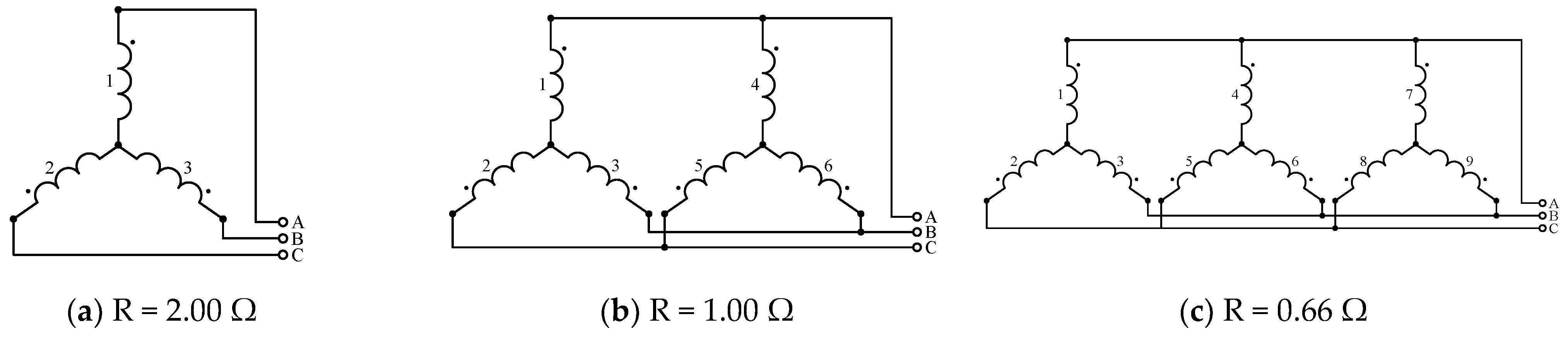
With 3 windings in each layer, the interconnection provides a choice of 15 possible schemes, among which the studied cases are provided
Figure 6. Each studied scheme is accompanied by an evaluation of its DC winding resistivity. Higher resultant DC resistivity leads to a higher torque under lower speed conditions, of course, if sufficient input electrical power is available. However, under higher speed conditions, a lower level of DC resistivity is beneficial and ensures the maximum mechanical output power.
In the case of heavy-lift drones transporting heavy payloads, larger-diameter propellers with a small pitch for high stroke and low Kv are used. Lower propeller speed operational conditions may be provided by a reduction gear, which, however, increases the weight. Alternatively, it is possible to modify the stator windings, i.e., the number of turns and their interconnection. The proposed approach in terms of a multilayer structure is thus suitable for heavy-lift drones, because it reduces Kv and keeps the outer diameter small. It also reduces the moment of inertia and provides low weight. In contrast to conventional BLDC motors, e.g., AXI 5320/18 GOLD LINE V2 with Kv 370 RPM/V and the delta winding interconnection suitable for large propellers [
22], the proposed solution enables the windings to be switched from the delta to star interconnection. This change in the winding interconnection reduces the Kv, and further reduces Kv by the ratio defined by the number of layers. The proposed solution in theory with 18 turns (the current functional design has 8 turns) might thus reach Kv even below 100 RPM/V. It may fit heavy-lift UAV operation with large propellers better, and may eliminate the need for an additional gear, which would increase the overall weight. It further increases an operational efficiency with higher torque under low propeller speed conditions. The solution therefore has a large variety of applications demanding a rapid response of the propeller speed to UAV stability control requirements.
The proposed solution with multiple layers and N × 3 windings (in functional design N = 3) also brings another benefit in terms of the ability to change/switch the winding interconnections between star/delta schemes on demand, with an additional electronic “automatic gear”. An alternative using three FETs is shown in
Figure 7. The delta interconnection can deliver more power than the star interconnection under higher-speed conditions. Conversely, the star interconnection can achieve higher torque under low-speed conditions. When this aspect is considered, the star interconnection can be assumed to be beneficial within the start-up stage due to the lower speed. However, the delta interconnection can achieve greater efficiency and can deliver more power during flight. The proposed solution with the ability to switch winding interconnections can thus employ the benefits of both variants and can therefore optimize the overall performance. For star/delta switching, both ends of the motor windings must be brought out to the terminal box. This type of structure is rather unusual in terms of conventional BLDC motors, which are in most cases permanently connected in the delta interconnection.
When the winding interconnection is switched, the phase voltage is simultaneously affected. Within the starting phase, when switched from the (original) delta interconnection to the star winding interconnection, the change reduces the voltage applied to each phase to about 58% (i.e., 1/√3) of its line-to-line original value, resulting also in a reduction in current. The reduced current that is drawn is approximately one third of its original value. This causes a decreased level of heat radiation, which is welcome. To support the torque even more under these conditions, a higher in-voltage applied for the motor control would be beneficial. The in-voltage increase may be in the range in which the electrical limits of the windings are not overdrawn, but the phase voltage reduction in the star interconnection against the delta interconnection serves the situation well. When all of this is considered, the overall motor performance may be improved even under low-speed conditions, where the motor in general suffers more from heating issues. As already mentioned, the star configuration is beneficial because of its ability to produce higher torque under low-speed conditions. When a higher voltage level is used simultaneously, it would bring the benefits of a lower heat radiation level and better performance.
4. Experimental Verification and Results
The windings were connected to different interconnection schemes based on the overview in
Figure 6; the input electrical power and the torque were measured for each scheme, i.e., a- to h-, and for different speed conditions. The results from the experiments are summarized in
Table 1 and
Table 2, and are shown in
Figure 11 and
Figure 12.
Since the experimental setup suffered from an initial inertial load in the form of the rotor and clutch of the dynamometer, while the BLDC motor control was performed on the basis of back EMF zero-crossing detection, it was not possible to establish rotations in the a-, d-, and e-winding interconnections. The initial mechanical power under these conditions was too low to overcome the initial load. For this reason, the results for these interconnections are not presented here. In addition, the b-, f-interconnections suffered from the same effect, which caused them to start rotating from 1500 RPM. Under lower speed conditions, the motor did not establish stable rotation, and did not provide output shaft rotation at all.
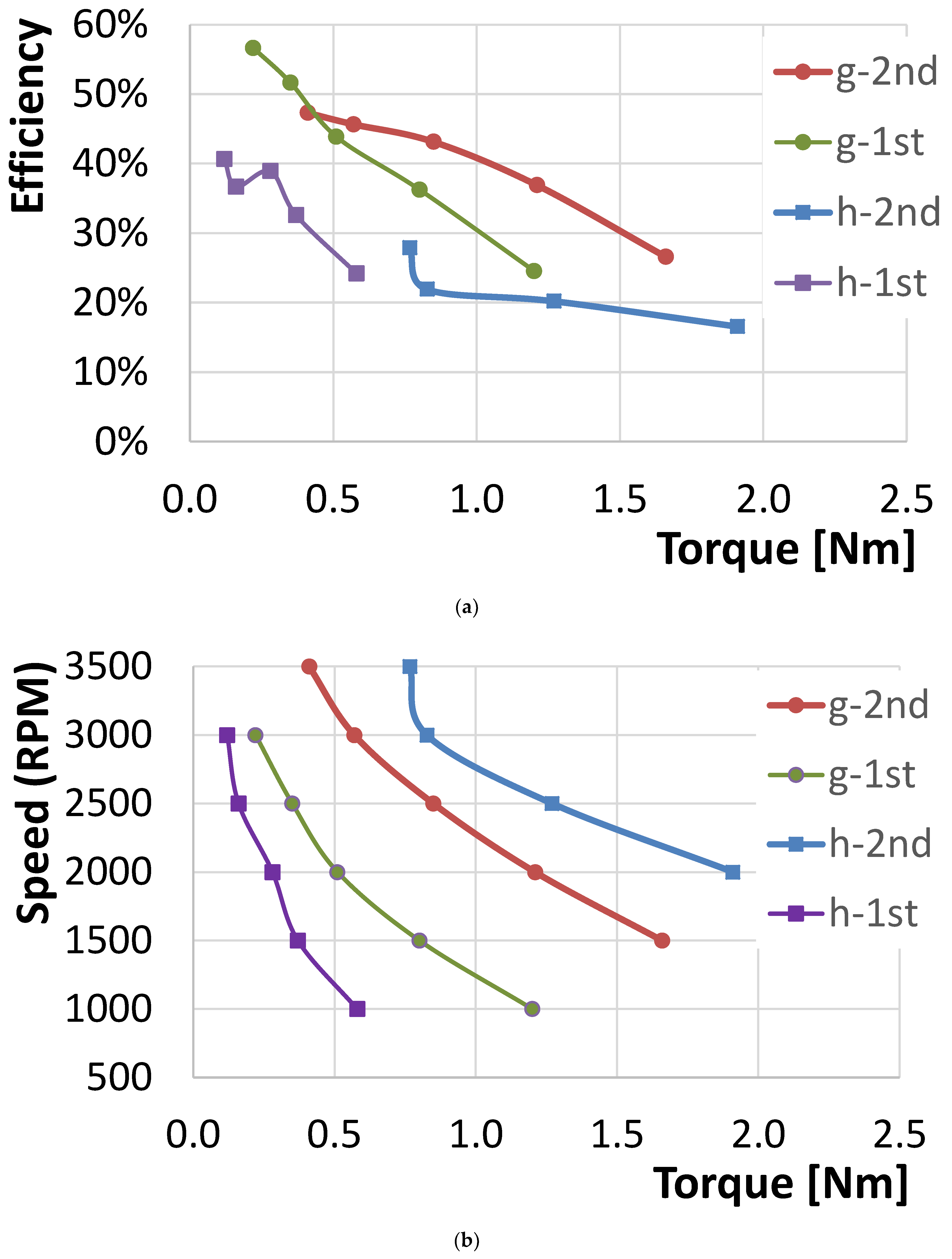
According to the accomplished results, the winding g-interconnection, i.e., a star scheme using three windings from each layer connected in a serial circuit for a single phase, performed with the highest torque that was achieved, and with the highest efficiency. This fully confirmed the theoretical assumption that the star g-interconnection with R = 6.00 Ω had the greatest torque. Conversely, the triple delta h-interconnection with R = 0.22 Ω achieved the lowest torque in the highest speed conditions that were tested.
To confirm these results, another series of experiments was performed with the same setup, but only two serially connected 12 V car batteries were used, instead of the Li-Pol 24 V battery. The new setup showed the functional design performing without a current limitation. In this case, only h- and g-interconnections were studied. The results are presented in
Table 3 and are shown in
Figure 13 and
Figure 14. The efficiency decreased within the 2nd round of experiments since the power supply changed and was able to provide a higher current. This led simultaneously to increased power losses in terms of heating, which influenced the efficiency, mainly under low-speed conditions. However, the torque levels increased.
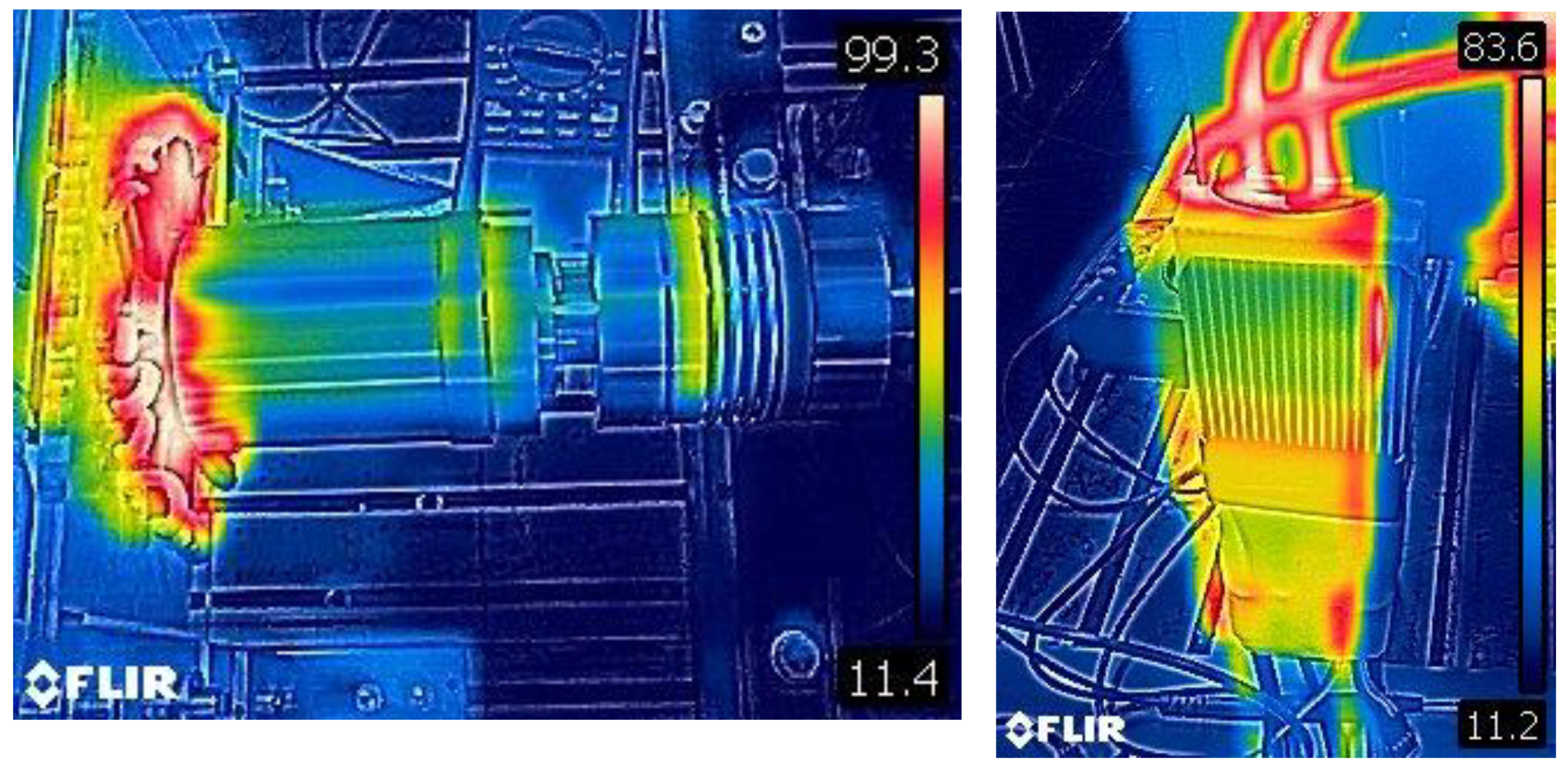
Since the design had the outrunner construction, the heating aspect needed to be observed. In general, the lower the maintained speeds are, the more dominant the observed effect of heating is
Figure 15a shows the stator temperature, which reached almost 100 °C when the motor was powered by a current of 100 A and a voltage of about 24 V. This corresponded to low-speed conditions. The power was taken from two serially connected 12 V car batteries in this case.
Figure 15b shows the heat radiation from the ESC unit and the corresponding cables. This heating was caused by the fact that the high Kv BLDC motor was operated under low-speed conditions, which meant that a significant part of the current was transferred to heat. While a higher speed was established, the time related to a single phase was shorter, and so was the time for the current to be transformed to heat.
The advantage of the proposed solution is shown by the fact that the BLDC motor in g-interconnection worked steadily at the lowest speed without losing synchronization, even if the design used only 8 turns of the windings and therefore had high Kv. On the other hand, the c- and f-interconnections confirmed that having three parallel layers of a standard stator in a single BLDC motor axis increased the torque even under low-speed conditions, which might not be possible for a standard single-layer stator configuration.
5. Analysis of the Uncertainty of the Experimental Data
The results presented in
Section 4 were obtained from measurements that suffered from inaccuracies. Those inaccuracies can be defined via the uncertainty, i.e., the combined uncertainty (
) consisted of a standard uncertainty of Type A (
) and of Type B (
) and can be defined as:
where
X represents the evaluated quantity. The combined uncertainty is typically multiplied by a coverage factor of k = 2 (or 3) to increase the interval of confidence to approximately 95% (k = 2), or to approximately 99% (k = 3). The resultant value is then called the expanded uncertainty.
The Type A standard uncertainty is evaluated based on a statistical analysis of a series of observations by means of the mean value and the standard deviation. Conversely, the Type B standard uncertainty evaluation is based on a specification of the accuracy of the device. The uncertainty of Type B is defined as:
where
represents the
quantity measured or estimated,
corresponds to the uncertainty of its measurement/estimation, and
is its sensitivity coefficient, defined as:
where
. Therefore,
corresponds to the partial derivatives of function
with respect to individual quantities
.
In the case of the experimental setup, the accuracy specification is denoted in
Table 4. The specifications are accompanied by the evaluated uncertainties. The fluctuation of the readings was considered only in the case of the amperemeter, where it played a meaningful role, and therefore the Type A uncertainty needed to be estimated in this case. The fluctuation was estimated within 5% of the read value. This aspect unfortunately influenced the overall accuracy of the input electrical power and particularly the final efficiency the most.
Table 4 provides maximum values as representatives of the estimated uncertainties obtained from individual measurements.
The maximum expanded uncertainties of the results in terms of the input electrical power, the output mechanical power, and the related efficiency, when the maximum combined uncertainties from
Table 4 were considered, are provided in
Table 5.
6. Conclusions
This paper has focused on BLDC motors. It has proposed a solution using a multilayer stator/rotor structure that enables the use of different stator winding interconnections and increases the torque even under low-speed conditions. A conventional way to do this increases the number of stator slots in a single layer. Unfortunately, this leads to a greater rotor diameter and a heavier mass of the rotor, which increases the moment of inertia. This fact has a negative effect on the dynamic response of a UAV motor control in weather-complicated situations and/or in highly dynamic maneuvers. Conversely, the proposed solution increases the number of stator slots by placing three standard stators in parallel along the main axis of the motor, forming a multilayer structure without increasing the diameter of the rotor. The proposed solution can therefore achieve more torque, even under low-speed conditions where a conventional configuration is too weak to establish rotation. The experimental results confirmed that a big star configuration, i.e., when, for a single phase, three serially connected windings were used from each layer, performed with the highest torque and with the highest efficiency, even under low-speed conditions. Conversely, the conventional structure using a single layer was not able to establish rotation under the same conditions. This showed the suitability of the approach for application to heavy-lift UAVs, where large propellers with a small pitch are used and low Kv motors are recommended.
The BLDC motor used for the experiments was in the development stage as a functional design without CA/CB safety tests. For safety reasons, the experiments were therefore performed with a voltage level of 24 V only. The multi-stator configuration enabled a larger number of winding interconnection schemes to be studied. The results confirmed that the proposed approach of the multilayer stator configuration, when all layers were employed, increased the torque even under low-speed conditions and the rotation was still controllable with a standard ESC controller. The experiments suffered from low efficiency, i.e., the maximum value was 57%, and was affected by the inaccuracy specified in
Section 5. This was caused by the fact that the original functional design used only 8 turn windings and therefore had higher Kv. Nevertheless, it confirmed the approach in supporting the torque with a multilayer structure, which was the main aim of the study. A small number of turns also led to higher current levels, causing a greater heating effect, that degraded the efficiency of the motor.
This paper has further proposed an electronic winding interconnection switching capability that enables changes between the delta and star configuration in both directions on demand to obtain more efficient operation of the motor, depending on the flight phase. A final advantage of the proposed solution is that it uses standard COTS parts to construct a multilayer BLDC motor and a mid-price ESC regulator to control it. Thus, the solution indicates a new direction for increasing the torque of BLDC motors, while potentially minimizing the extra costs.


